EP3236149A1 - Générateur de vapeur à faisceau horizontal de tubes échangeurs de chaleur et procédé de son assemblage - Google Patents
Générateur de vapeur à faisceau horizontal de tubes échangeurs de chaleur et procédé de son assemblage Download PDFInfo
- Publication number
- EP3236149A1 EP3236149A1 EP15867195.8A EP15867195A EP3236149A1 EP 3236149 A1 EP3236149 A1 EP 3236149A1 EP 15867195 A EP15867195 A EP 15867195A EP 3236149 A1 EP3236149 A1 EP 3236149A1
- Authority
- EP
- European Patent Office
- Prior art keywords
- vessel
- heat
- steam generator
- exchange
- bundle
- Prior art date
- Legal status (The legal status is an assumption and is not a legal conclusion. Google has not performed a legal analysis and makes no representation as to the accuracy of the status listed.)
- Withdrawn
Links
- 238000000034 method Methods 0.000 title claims description 21
- XLYOFNOQVPJJNP-UHFFFAOYSA-N water Substances O XLYOFNOQVPJJNP-UHFFFAOYSA-N 0.000 claims abstract description 32
- 229910000831 Steel Inorganic materials 0.000 claims abstract description 14
- 238000001035 drying Methods 0.000 claims abstract description 14
- 239000010959 steel Substances 0.000 claims abstract description 14
- 238000004519 manufacturing process Methods 0.000 claims description 16
- 239000002826 coolant Substances 0.000 claims description 15
- 238000009826 distribution Methods 0.000 claims description 13
- 238000003466 welding Methods 0.000 claims description 12
- 239000003153 chemical reaction reagent Substances 0.000 claims description 10
- 238000011010 flushing procedure Methods 0.000 claims description 4
- 229910001562 pearlite Inorganic materials 0.000 claims description 3
- 239000011253 protective coating Substances 0.000 claims description 3
- 238000009434 installation Methods 0.000 claims description 2
- 239000002184 metal Substances 0.000 abstract description 10
- 230000003247 decreasing effect Effects 0.000 abstract description 3
- 238000000926 separation method Methods 0.000 description 8
- 239000000463 material Substances 0.000 description 6
- 238000001704 evaporation Methods 0.000 description 5
- 230000008020 evaporation Effects 0.000 description 5
- 229910001220 stainless steel Inorganic materials 0.000 description 5
- 239000010935 stainless steel Substances 0.000 description 5
- 238000005260 corrosion Methods 0.000 description 3
- 238000010276 construction Methods 0.000 description 2
- 230000007797 corrosion Effects 0.000 description 2
- 238000010438 heat treatment Methods 0.000 description 2
- 238000010248 power generation Methods 0.000 description 2
- 230000004308 accommodation Effects 0.000 description 1
- 238000009825 accumulation Methods 0.000 description 1
- 230000001174 ascending effect Effects 0.000 description 1
- 229910000963 austenitic stainless steel Inorganic materials 0.000 description 1
- 238000005452 bending Methods 0.000 description 1
- 238000000576 coating method Methods 0.000 description 1
- 238000000151 deposition Methods 0.000 description 1
- 230000008021 deposition Effects 0.000 description 1
- 230000000694 effects Effects 0.000 description 1
- JEGUKCSWCFPDGT-UHFFFAOYSA-N h2o hydrate Chemical compound O.O JEGUKCSWCFPDGT-UHFFFAOYSA-N 0.000 description 1
- 238000005304 joining Methods 0.000 description 1
- 230000001681 protective effect Effects 0.000 description 1
- 239000002002 slurry Substances 0.000 description 1
- 239000008400 supply water Substances 0.000 description 1
Images


Classifications
-
- G—PHYSICS
- G21—NUCLEAR PHYSICS; NUCLEAR ENGINEERING
- G21D—NUCLEAR POWER PLANT
- G21D1/00—Details of nuclear power plant
- G21D1/006—Details of nuclear power plant primary side of steam generators
-
- F—MECHANICAL ENGINEERING; LIGHTING; HEATING; WEAPONS; BLASTING
- F22—STEAM GENERATION
- F22B—METHODS OF STEAM GENERATION; STEAM BOILERS
- F22B1/00—Methods of steam generation characterised by form of heating method
- F22B1/02—Methods of steam generation characterised by form of heating method by exploitation of the heat content of hot heat carriers
- F22B1/023—Methods of steam generation characterised by form of heating method by exploitation of the heat content of hot heat carriers with heating tubes for nuclear reactors, as long as they are not classified according to a specified heating fluid, in another group
-
- F—MECHANICAL ENGINEERING; LIGHTING; HEATING; WEAPONS; BLASTING
- F22—STEAM GENERATION
- F22B—METHODS OF STEAM GENERATION; STEAM BOILERS
- F22B1/00—Methods of steam generation characterised by form of heating method
- F22B1/02—Methods of steam generation characterised by form of heating method by exploitation of the heat content of hot heat carriers
-
- F—MECHANICAL ENGINEERING; LIGHTING; HEATING; WEAPONS; BLASTING
- F22—STEAM GENERATION
- F22B—METHODS OF STEAM GENERATION; STEAM BOILERS
- F22B29/00—Steam boilers of forced-flow type
- F22B29/06—Steam boilers of forced-flow type of once-through type, i.e. built-up from tubes receiving water at one end and delivering superheated steam at the other end of the tubes
- F22B29/061—Construction of tube walls
- F22B29/064—Construction of tube walls involving horizontally- or helically-disposed water tubes
-
- F—MECHANICAL ENGINEERING; LIGHTING; HEATING; WEAPONS; BLASTING
- F22—STEAM GENERATION
- F22B—METHODS OF STEAM GENERATION; STEAM BOILERS
- F22B37/00—Component parts or details of steam boilers
- F22B37/02—Component parts or details of steam boilers applicable to more than one kind or type of steam boiler
-
- F—MECHANICAL ENGINEERING; LIGHTING; HEATING; WEAPONS; BLASTING
- F28—HEAT EXCHANGE IN GENERAL
- F28D—HEAT-EXCHANGE APPARATUS, NOT PROVIDED FOR IN ANOTHER SUBCLASS, IN WHICH THE HEAT-EXCHANGE MEDIA DO NOT COME INTO DIRECT CONTACT
- F28D7/00—Heat-exchange apparatus having stationary tubular conduit assemblies for both heat-exchange media, the media being in contact with different sides of a conduit wall
- F28D7/16—Heat-exchange apparatus having stationary tubular conduit assemblies for both heat-exchange media, the media being in contact with different sides of a conduit wall the conduits being arranged in parallel spaced relation
-
- F—MECHANICAL ENGINEERING; LIGHTING; HEATING; WEAPONS; BLASTING
- F28—HEAT EXCHANGE IN GENERAL
- F28F—DETAILS OF HEAT-EXCHANGE AND HEAT-TRANSFER APPARATUS, OF GENERAL APPLICATION
- F28F1/00—Tubular elements; Assemblies of tubular elements
-
- F—MECHANICAL ENGINEERING; LIGHTING; HEATING; WEAPONS; BLASTING
- F28—HEAT EXCHANGE IN GENERAL
- F28F—DETAILS OF HEAT-EXCHANGE AND HEAT-TRANSFER APPARATUS, OF GENERAL APPLICATION
- F28F9/00—Casings; Header boxes; Auxiliary supports for elements; Auxiliary members within casings
- F28F9/007—Auxiliary supports for elements
- F28F9/013—Auxiliary supports for elements for tubes or tube-assemblies
- F28F9/0132—Auxiliary supports for elements for tubes or tube-assemblies formed by slats, tie-rods, articulated or expandable rods
-
- G—PHYSICS
- G21—NUCLEAR PHYSICS; NUCLEAR ENGINEERING
- G21D—NUCLEAR POWER PLANT
- G21D5/00—Arrangements of reactor and engine in which reactor-produced heat is converted into mechanical energy
- G21D5/04—Reactor and engine not structurally combined
- G21D5/08—Reactor and engine not structurally combined with engine working medium heated in a heat exchanger by the reactor coolant
- G21D5/12—Liquid working medium vaporised by reactor coolant
-
- F—MECHANICAL ENGINEERING; LIGHTING; HEATING; WEAPONS; BLASTING
- F28—HEAT EXCHANGE IN GENERAL
- F28D—HEAT-EXCHANGE APPARATUS, NOT PROVIDED FOR IN ANOTHER SUBCLASS, IN WHICH THE HEAT-EXCHANGE MEDIA DO NOT COME INTO DIRECT CONTACT
- F28D21/00—Heat-exchange apparatus not covered by any of the groups F28D1/00 - F28D20/00
- F28D2021/0019—Other heat exchangers for particular applications; Heat exchange systems not otherwise provided for
- F28D2021/0061—Other heat exchangers for particular applications; Heat exchange systems not otherwise provided for for phase-change applications
- F28D2021/0064—Vaporizers, e.g. evaporators
-
- Y—GENERAL TAGGING OF NEW TECHNOLOGICAL DEVELOPMENTS; GENERAL TAGGING OF CROSS-SECTIONAL TECHNOLOGIES SPANNING OVER SEVERAL SECTIONS OF THE IPC; TECHNICAL SUBJECTS COVERED BY FORMER USPC CROSS-REFERENCE ART COLLECTIONS [XRACs] AND DIGESTS
- Y02—TECHNOLOGIES OR APPLICATIONS FOR MITIGATION OR ADAPTATION AGAINST CLIMATE CHANGE
- Y02E—REDUCTION OF GREENHOUSE GAS [GHG] EMISSIONS, RELATED TO ENERGY GENERATION, TRANSMISSION OR DISTRIBUTION
- Y02E30/00—Energy generation of nuclear origin
-
- Y—GENERAL TAGGING OF NEW TECHNOLOGICAL DEVELOPMENTS; GENERAL TAGGING OF CROSS-SECTIONAL TECHNOLOGIES SPANNING OVER SEVERAL SECTIONS OF THE IPC; TECHNICAL SUBJECTS COVERED BY FORMER USPC CROSS-REFERENCE ART COLLECTIONS [XRACs] AND DIGESTS
- Y02—TECHNOLOGIES OR APPLICATIONS FOR MITIGATION OR ADAPTATION AGAINST CLIMATE CHANGE
- Y02E—REDUCTION OF GREENHOUSE GAS [GHG] EMISSIONS, RELATED TO ENERGY GENERATION, TRANSMISSION OR DISTRIBUTION
- Y02E30/00—Energy generation of nuclear origin
- Y02E30/30—Nuclear fission reactors
Definitions
- This invention relates to electric power industry, and more particularly to horizontal steam generators for nuclear power plants with a water-water energetic reactor (VVER).
- VVER water-water energetic reactor
- Horizontal steam generators are widely used in the field of electric power generation that are not designed for nuclear industry application, but have a number of significant features consistent with those of the steam generators applied at nuclear power plants. Such is, for instance, the steam generator described in application for European patent EP1927809 , IPC: F22B1/02 issued on 6/4/2008.
- the steam generator has a drum-shaped pressure vessel.
- the vessel longitudinal axis is horizontal or generally horizontal.
- the vessel accommodates hollow heat-exchange tubes grouped into sections and arranged mostly in parallel to one another, and secured in a supporting frame.
- the claimed invention relates to generally horizontal steam generators for nuclear power plants (the "steam generator"), for example, to steam generators as described in International application WO9320386 (issued on 10/14/1993 , IPC F22B1/02) and International application WO9320385 (issued on 10/14/1993 , IPC F22B1/02), and does not relate to vertical steam generators.
- the said known horizontal steam generators for nuclear power plants do not have tube sheets in their design. Instead, two vertical cylinder headers are included in the horizontal steam generator vessel, namely, an inlet header and an outlet header of the primary circuit coolant connected to a horizontal heat-exchange tube bundle. Horizontally arranged heat-exchange tubes are mounted in the vertical cylinder surface of the said headers. Manufacturing process of the primary circuit coolant cylinder headers requires a lower specific amount of metal per structure than that of a tube sheet.
- the closest analog of the claimed invention is the steam generator disclosed in patent RU30928 (issued on 7/10/2003 , IPC F22B1/02).
- This steam generator comprises a vessel, inlet and outlet headers with a horizontal in-line heat-exchange tube bundle connected to the same and equipped with spacing devices and divided into banks with vertical intertubular tunnels between them.
- Horizontal heat-exchange tubes are installed at a horizontal and vertical relative spacing of (1.44 ⁇ 1.55) ⁇ d and (1.35 ⁇ 1.40) ⁇ d respectively, where d is the heat-exchange tube diameter.
- This technical solution allows to select an optimal spacing for arrangement of heat-exchange tubes in a bundle, but does not maintain the steam generator overall dimensions, which are necessary and sufficient to increase the efficiency of heat exchange between the primary and secondary circuit coolants within the steam generator volume.
- the increased steam generator vessel length or diameter allows to increase the heat-exchange surface area, however, it leads to a number of disadvantages:
- the closest analog of the proposed method of horizontal steam generator assembly is the method described in book " Steam Generator Units of Nuclear Power Plants” by N. G. Rassokhin, Moscow, Energatomizdat, 1987, pp. 65-68 .
- the said method requires manufacturing a steam generator welded cylinder steel vessel of forged shells, two pressed elliptical bottoms, an inlet header and an outlet header of the primary circuit coolant, feed water and chemical reagent headers, and other vessel internals, as well as a bundle of U-shaped heat-exchange tubes.
- the purpose of the invention is to create a steam generator complying with the reliability, ease of manufacturing requirements with an increased steam generation capacity without significant increase of the main overall dimensions.
- the technical result is a decreased specific amount of metal per structure of the steam generator vessel while drying the generated steam in the same vessel with a heat-exchange surface.
- a steam generator with a horizontal heat-exchange tube bundle comprising a welded cylinder vessel manufactured of steel shells and equipped with at least one feed water supply connection pipe and one steam removal connection pipe, and two elliptical bottoms, vessel internals, inlet and outlet headers connected to the heat-exchange tube bundle forming a heat-exchange surface of the steam generator, where inner diameter dvess of the steam generator vessel is selected based on the following relations: 0.148 ⁇ D + 0.637 ⁇ 0.054 ⁇ D 2 + 3.142 ⁇ N tb ⁇ S h ⁇ S v k ⁇ dvess ⁇ 1.827 ⁇ H , where:
- the steam generator vessel is filled with heat-exchange bundle tubes from the bottom upwards to the height of three quarters of its inner diameter or less, the remaining space in the top part of steam generator vessel is left for steam drying. H ⁇ 3/4 dvess.
- the tubes in steam generator heat-exchange bundles are grouped in banks separated by 100 to 250 mm-wide vertical intertubular tunnels serving to improve circulation and arrange supporting elements for fastening and spacing of tubes.
- the steam generator heat-exchange tubes bundle is filled with heat-exchange tubes from bottom upwards continuously with uniform vertical gaps between adjacent tubes not exceeding the vertical spacing of tubes in the bundle.
- the steam generator includes at least the following internals: a feed water supply and distribution device located above the heat-exchange tube bundle, an emergency feed water supply and distribution device located in the steam space, device for chemical reagent supply during steam generator flushing, a submerged perforated sheet with variable perforation and an overhead perforated sheet.
- the second object of the claimed invention is assembly method for steam generator vessel with a horizontal heat-exchange tube bundle including manufacturing of steel shells with inner diameter dvess., assembly and welding of shells in order to form a cylinder vessel, equipment of the vessel with at least a feed water supply connection pipe and a steam removal connection pipe, inlet and outlet headers, connection of the same with a heat-exchange tube bundle, arrangement of vessel internals, installation of two elliptical bottoms on the cylinder vessel ends, followed by their welding to the vessel.
- Vessel assembly is performed by aligning the shells, for example, two thicker shells are aligned first forming the central part of the vessel and welded together. Then, two thinner shells are aligned and welded with the vessel central part on both sides.
- Inner diameter dvess of the vessel is chosen based on the following ratios: 0.148 ⁇ D + 0.637 ⁇ 0.054 ⁇ D 2 + 3.142 ⁇ N tb ⁇ S h ⁇ S v k ⁇ dvess ⁇ 1.827 ⁇ H , where:
- the steam generator cylinder vessel is assembled from three forged shells joined by weld seams.
- the steam generator cylinder vessel can be assembled from four forged shells joined by weld seams.
- Materials for the steam generator vessel are high-strength pearlite grade steels, including steel 10GN2MFA.
- the steam generator vessel has its inner diameter of maximum 4200 mm in order to facilitate rail road transportation issues.
- Heat-exchange tubes are formed into U-shaped coils by bending in stages and are arranged in a bundle. Tubes are installed with hydraulic slope towards primary circuit coolant headers in a heat-exchange bundle in order to provide complete draining of heat-exchange tubes.
- weld seams on the steam generator cylinder vessel are subjected to mechanical and heat treatment and covered with a protective coating.
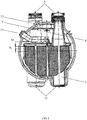
- a steam generator for VVER nuclear power plants is a horizontal single-vessel heat-exchange unit with an immersed heat-exchange surface comprising the following components as shown in the enclosed figures: a vessel 1, a heat-exchange tube bundle 2 (also referred to as tube bundle, heat-exchange bundle), inlet and outlet headers 3 of the primary circuit coolant, a feed water supply and distribution device 4, an emergency feed water supply and distribution device 5, an overhead perforated sheet 6, a submerged perforated sheet 7, a chemical reagent supply device 8.
- the vessel (1) determines the main dimensions of the steam generator, it accommodates inlet and outlet headers (3) of the primary circuit, a heat-exchange surface in the form of heat-exchange tube bundle (2) and vessel internals.
- the vessel 1 is a horizontally elongated welded cylinder container with elliptical bottoms 10 with manholes 11 for access to the secondary circuit volume positioned on them welded to its both ends.
- the vessel 1 also contains primary circuit coolant supply and removal connection pipes 12, steam removal connection pipes 13 feed water supply connection pipes 14 and other connection pipes and access manholes.
- Headers 3 of the primary circuit coolant are thick-walled cylinders of varying diameters and thickness. They are made of high-strength pearlite grade steel, and their internal surfaces have a protective anti-corrosion build-up.
- the central cylinder part of headers 3 has perforations for fastening the ends of heat-exchange tubes 15.
- the upper part of headers 3 has a split for access inside through manholes 9 of the secondary circuit.
- the heat-exchange surface of the steam generator is formed by heat-exchange tubes (15) made of austenitic stainless steel of the 08Cr18Ni10Ti grade.
- Heat-exchange tubes are formed into U-shaped coils arranged in bundle 2 and installed with a slope towards headers 3 in order to provide possibility of complete draining of heat-exchange tubes 15.
- Heat-exchange tubes 15 are fixed in headers 3 by counter welding of the ends with the internal surface of the headers 3. Hydraulic expansion of heat-exchange tubes 15 is performed over wall thickness of the headers 3 with mechanical curling near the external surface of the headers 3 until the of gap (split) between the headers 3 and the heat-exchange tubes 15 is closed.
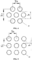
- Heat-exchange tubes (15) are installed with a gap at certain intervals from one another (spaced in bundle (2)) using spacing elements (16), such as wave-shaped bands and flat plates ( Fig. 3 ). This fixing structure allows the heat-exchange tubes 15 to move during thermal expansion.
- Internal devices located in the vessel 1 include the following:
- the operation principle of the steam generator structure is as follows. Coolant heated in reactor is supplied to the inlet or distributing header of the primary circuit coolant (one of headers 3). From the distributing header, it is fed to heat-exchange tubes (15), moves through them transferring the heat through the heat-exchange surface wall to the boiler water, and is collected in the outlet or collecting header of the primary circuit coolant (the other header (3)). The coolant is returned to the reactor from the collector header by a circulating pump.
- the steam generator vessel 1 is filled with boiler water to a certain level which is to be maintained during operation. Feed water is supplied to the steam generator by the feed water supply and distribution device 4. The feed water flowing out of it is mixed with the boiler water and heated to the saturation temperature.
- the heat transferred from the coolant is spent on boiler water evaporation and steam generation in the intertubular space of the steam generator.
- the generated steam is ascending to the separation part of the steam generator comprising a free volume, separation devices or a combination thereof. After passing the separation part of the steam generator, the steam has the design rated humidity. Then it is removed from the steam generator through steam removal devices comprising steam removal connection pipes 13 and overhead perforated sheets 6 installed in front of them.
- the steam generated by the steam generator is used in steam-power process cycle of electric power generation.
- an emergency feed water supply and distribution device (5), a chemical reagent supply device (8), an overhead perforated sheet (6), a submerged perforated sheet (7) are optional (non-critical) components of a steam generator. They are required to improve the steam generator operation reliability, durability, etc., and may either included or not in different horizontal steam generator structures.
- An emergency feed water supply and distribution device 5 is used to supply water to the steam generator if the main feed water line is damaged and during cooldown of the reactor plant through the secondary circuit in case of a design basis accident.
- a chemical reagent supply device 8 is used during regular flushing of the steam generation for removal of the accumulated depositions and corrosion products. This device is used to supply chemical reagents to the steam generator.
- a submerged perforated sheet 7 is used to level the steam load in the steam generator steam space. This is required to provide separation parameters of the steam generation and is only relevant for high-power steam generators.
- An overhead perforated sheet 6 is used to form an even profile of steam velocities in the steam generator steam space by creating resistance on its way, which is required to provide reliable steam separation in the steam generator.
- a horizontal steam generator for a nuclear power plant is assembled as follows: First, a cylinder vessel (1) is manufactured, for example, from four forged steel shells. The steam generator vessel is assembled in a horizontal or vertical position. For instance, vertical assembly is performed by up-building of steel shells one upon another form bottom upwards by subsequent alignment of all four shells. The vertical assembly method increases the assembly accuracy while minimizing the costs. During the assembly, the aligned shells are connected by welding process tabs to the joint area in the quantity sufficient for rigid connection of the shells. In this case, to facilitate welding operations at height, auxiliary internal and external ring platforms for welders are created.
- the assembled vessel is returned to the horizontal position using lifting cranes, the weld seam groves are checked, then, the next operation of automatic welding of ring seams is performed. After that, welded seams are subjected to heat treatment and protective coatings are built up on the internal surface of the steam generator vessel. Thermodiffusion coatings may be applied additionally afterwards.
- one-piece or two-component pressed elliptical bottoms (11), a feed water supply and distribution device (4), steam removal connection pipes (13), inlet and outlet headers (3), heat-exchange tubes (15) with outer diameter dtb in quantity Ntb are manufactured.
- the above devices are installed and fixed in the vessel (1), in particular, the headers (3), supports for the heat-exchange tube bundle (2) and other specified vessel internals are welded to the vessel (1).
- the elliptical bottoms 11 are installed and welded onto the vessel 1. Weld seams joining the steam generator vessel and the bottoms, are covered with build-up on the internal surface of the steam generator vessel.
- the following devices may also be manufactured and installed in the vessel (1): an emergency feed water supply and distribution device (5), a chemical reagent supply device (8), an overhead perforated sheet (6), and a submerged perforated sheet (7).
- an emergency feed water supply and distribution device (5) a chemical reagent supply device (8), an overhead perforated sheet (6), and a submerged perforated sheet (7).
- These elements are optional for the steam generator, however, as it was mentioned above, they are designed to improve steam generator operation.
- the steam generator vessel (1) is filled with heat-exchange bundle tubes (2) from the bottom upwards to the height of three quarters of the vessel inner diameter or less, the remaining space in the top part of steam generator vessel is left for steam drying.
- the heat-exchange bundle tubes are grouped in banks as shown in Fig. 2 , that are separated by vertical intertubular tunnels with the width from 100 to 250 mm.
- the steam generator vessel is filled with the heat-exchange bundle tubes from the bottom upwards to the height of three quarters of its inner diameter or less, but not lower than 150 to 400 mm above the horizontal axis of the steam generator vessel.
- the heat-exchange tube bundle (2) is formed so that it is filled with heat-exchange tubes (15) continuously from bottom upwards. Spacing elements 16 ensure gaps in the heat-exchange tube bundle 2 that do not exceed the vertical spacing of heat-exchange tubes 15 in the bundle 2.
- the steam generator vessel is manufactured as a welded cylinder vessel from four forged shells with two pressed elliptical bottoms connected to each end of the vessel.
- the steam drying parameters of the steam generator depend on the value and configuration of steam space above the evaporation surface.
- the heat-exchange bundle tubes covered by the boiler water i.e. submerged under the evaporation surface, shall be grouped in banks with a height of three quarters of the inner diameter of the steam generator vessel or less (H ⁇ 3/4 dvess), the remaining space in the top part of steam generator vessel is left for steam drying. Under these conditions, suitable steam drying parameters are achieved.
- the evaporation surface width will also be approximately 4/5 dvess, and separation section height will be 1/5 dvess.
- the steam generator separation section will have a shape of a confuser with a large convergence angle, and steam separation in the steam generator vessel will become impossible.
- a high-power steam generator is manufactured.
- the SG steam generation capacity is set at 4000 t/h level.
- heat-exchange tubes with outer diameter 12 mm are used.
- the tubes are arranged with the minimum gap of 2 mm.
- the specific amount of metal per structure is decreased by selection of the steam generator vessel diameter within the range of minimum values sufficient for accommodation of the set number of heat-exchange tubes at the set spacing for the set arrangement, providing that steam is dried in the steam space located above the heat-exchange bundle.
- the empiric relation between the vessel diameter and the number of heat-exchange tubes in a bundle specified in the claimed invention allows to determine the minimum vessel diameter required to place the set number of tubes for the set arrangement and spacing, provided that the steam is dried in the steam space located above heat-exchange bundle.
- the heat-exchange bundle tubes are laid in rows in tube banks inside the vessel. Heat-exchange tube banks have a height of three quarters of the steam generator vessel diameter or less and are covered with boiler water completely. The remaining space in the steam generator vessel is used for steam drying.
Landscapes
- Engineering & Computer Science (AREA)
- Physics & Mathematics (AREA)
- General Engineering & Computer Science (AREA)
- Mechanical Engineering (AREA)
- Thermal Sciences (AREA)
- Life Sciences & Earth Sciences (AREA)
- Sustainable Development (AREA)
- Sustainable Energy (AREA)
- High Energy & Nuclear Physics (AREA)
- Plasma & Fusion (AREA)
- Heat-Exchange Devices With Radiators And Conduit Assemblies (AREA)
- Monitoring And Testing Of Nuclear Reactors (AREA)
- Details Of Heat-Exchange And Heat-Transfer (AREA)
- Drying Of Solid Materials (AREA)
Applications Claiming Priority (2)
| Application Number | Priority Date | Filing Date | Title |
|---|---|---|---|
| RU2014150429/06A RU2583321C1 (ru) | 2014-12-12 | 2014-12-12 | Парогенератор с горизонтальным пучком теплообменных труб и способ его сборки |
| PCT/RU2015/000786 WO2016093737A1 (fr) | 2014-12-12 | 2015-11-16 | Générateur de vapeur à faisceau horizontal de tubes échangeurs de chaleur et procédé de son assemblage |
Publications (2)
| Publication Number | Publication Date |
|---|---|
| EP3236149A1 true EP3236149A1 (fr) | 2017-10-25 |
| EP3236149A4 EP3236149A4 (fr) | 2018-11-21 |
Family
ID=55959894
Family Applications (1)
| Application Number | Title | Priority Date | Filing Date |
|---|---|---|---|
| EP15867195.8A Withdrawn EP3236149A4 (fr) | 2014-12-12 | 2015-11-16 | Générateur de vapeur à faisceau horizontal de tubes échangeurs de chaleur et procédé de son assemblage |
Country Status (14)
| Country | Link |
|---|---|
| US (1) | US20170321880A1 (fr) |
| EP (1) | EP3236149A4 (fr) |
| JP (1) | JP6616425B2 (fr) |
| KR (1) | KR102190135B1 (fr) |
| CN (1) | CN107250663B (fr) |
| AR (1) | AR102983A1 (fr) |
| BR (1) | BR112017012523B1 (fr) |
| CA (1) | CA2970612C (fr) |
| EA (1) | EA032818B1 (fr) |
| JO (1) | JOP20150311B1 (fr) |
| MY (1) | MY190440A (fr) |
| RU (1) | RU2583321C1 (fr) |
| UA (1) | UA121124C2 (fr) |
| WO (1) | WO2016093737A1 (fr) |
Families Citing this family (8)
| Publication number | Priority date | Publication date | Assignee | Title |
|---|---|---|---|---|
| RU180906U1 (ru) * | 2017-09-18 | 2018-06-29 | Сергей Леонидович Лякишев | Корпус горизонтального парогенератора |
| HUE070356T2 (hu) * | 2017-12-29 | 2025-05-28 | Joint Stock Company Atomenergoproekt | Kétkörös atomreaktor gõzfejlesztõ létesítménye lefúvató és ürítõ rendszerrel |
| US12057240B2 (en) * | 2018-07-02 | 2024-08-06 | Invap S.E. | Compact reactor with horizontal steam generators and pressurizer |
| RU2745915C1 (ru) * | 2020-03-25 | 2021-04-02 | Акционерное общество "Инжиниринговая компания "АЭМ-технологии" (АО "АЭМ-технологии") | Способ местной термической обработки сварных соединений |
| CN113617041B (zh) * | 2021-07-21 | 2022-11-29 | 邳州市鑫盛创业投资有限公司 | 一种酒精加工用再沸器 |
| CN115770995B (zh) * | 2022-12-06 | 2025-05-09 | 哈尔滨锅炉厂有限责任公司 | 一种异形蒸发器管束的组装装置及方法 |
| CN115790242B (zh) * | 2023-01-29 | 2023-05-09 | 江苏银环精密钢管有限公司 | 一种卡齿及高温气冷堆蒸汽发生器换热单元组件组装方法 |
| CN119267883B (zh) * | 2024-11-11 | 2026-02-17 | 江西心连心化学工业有限公司 | 一种管束滑动结构的蒸汽发生器 |
Family Cites Families (30)
| Publication number | Priority date | Publication date | Assignee | Title |
|---|---|---|---|---|
| JPS5816081B2 (ja) * | 1978-04-24 | 1983-03-29 | 株式会社日立製作所 | 蒸気発生装置 |
| JPS56172673U (fr) * | 1980-05-23 | 1981-12-19 | ||
| FR2500676A1 (fr) * | 1981-02-24 | 1982-08-27 | Commissariat Energie Atomique | Dispositif de refroidissement de secours d'un reacteur nucleaire refroidi a l'eau |
| US4654190A (en) * | 1984-04-05 | 1987-03-31 | Westinghouse Electric Corp. | Emergency feedwater system for steam generators of a nuclear power plant |
| SU1267847A1 (ru) * | 1984-11-13 | 1996-01-10 | Г.А. Таранков | Узел парогенератора |
| DE3522646A1 (de) * | 1985-06-25 | 1987-01-08 | Wiederaufarbeitung Von Kernbre | Formkoerper aus schlecht schweissbarem werkstoff |
| JP2999053B2 (ja) * | 1992-02-27 | 2000-01-17 | 三菱重工業株式会社 | 加圧水型原子炉プラント |
| CZ288U1 (cs) * | 1992-04-03 | 1993-04-28 | Vítkovice, A.S. | Napájecí soustava tepelného výměníku, zejména parogenerátoru |
| RU2052710C1 (ru) * | 1992-05-19 | 1996-01-20 | Опытное Конструкторское Бюро "Гидропресс" | Барабан парогенератора |
| JPH06299233A (ja) * | 1993-04-09 | 1994-10-25 | Hitachi Ltd | 耐高温高圧水中応力腐食割れ性に優れた炭素鋼の熱処理法 |
| JPH06300201A (ja) * | 1993-04-20 | 1994-10-28 | Mitsubishi Heavy Ind Ltd | 横置蒸気発生器 |
| FR2705047B1 (fr) * | 1993-05-12 | 1995-08-04 | Framatome Sa | Procede et dispositif de soudage par faisceau d'electrons de deux pieces d'un composant de grande dimension et notamment d'un generateur de vapeur d'un reacteur nucleaire a eau sous pression. |
| RU2068149C1 (ru) * | 1993-08-13 | 1996-10-20 | Опытное Конструкторское Бюро "Гидропресс" | Парогенератор |
| JPH11294706A (ja) * | 1998-04-08 | 1999-10-29 | Mitsubishi Heavy Ind Ltd | シェル・チューブ熱交換器型横置蒸気発生器 |
| RU2184997C2 (ru) * | 2000-07-27 | 2002-07-10 | Опытное Конструкторское Бюро "Гидропресс" | Установка для дезактивации теплообменной поверхности парогенератора |
| RU2219433C2 (ru) * | 2001-09-06 | 2003-12-20 | Государственное унитарное предприятие Опытное конструкторское бюро машиностроения им. Африкантова И.И. | Парогенератор |
| US6626235B1 (en) * | 2001-09-28 | 2003-09-30 | Ignas S. Christie | Multi-tube heat exchanger with annular spaces |
| RU157393U1 (ru) * | 2003-01-21 | 2015-11-27 | ОАО "Инжиниринговая компания "ЗиОМАР" | Парогенератор |
| EP2278220B1 (fr) * | 2009-06-24 | 2014-03-05 | Balcke-Dürr GmbH | Echangeur thermique destiné à la production de vapeur pour une centrale thermique solaire |
| RU88773U1 (ru) * | 2009-06-25 | 2009-11-20 | Открытое акционерное общество "Всероссийский научно-исследовательский институт по эксплуатации атомных электростанций" (ОАО "ВНИИАЭС") | Парогенератор |
| JP2011122804A (ja) * | 2009-12-14 | 2011-06-23 | Fuji Denki Thermosystems Kk | 水蒸気発生装置 |
| RU100590U1 (ru) * | 2010-08-02 | 2010-12-20 | Открытое акционерное общество "Ордена Трудового Красного Знамени и ордена труда ЧССР опытное конструкторское бюро "Гидропресс" | Парогенератор |
| DE102010039413B4 (de) * | 2010-08-17 | 2012-03-29 | Areva Np Gmbh | Verfahren und Vorrichtung zur Entnahme einer Probe aus einem Dampferzeuger |
| US9343187B2 (en) * | 2010-09-27 | 2016-05-17 | Bwxt Nuclear Energy, Inc. | Compact nuclear reactor with integral steam generator |
| ES2707300T3 (es) * | 2011-01-05 | 2019-04-03 | Westinghouse Electric Co Llc | Accesorio de limpieza in situ de álabes desempañadores de niebla |
| JP2012184834A (ja) * | 2011-03-08 | 2012-09-27 | Mitsubishi Heavy Ind Ltd | 圧力容器の支持方法 |
| UA78828U (en) * | 2012-02-06 | 2013-04-10 | Иван Александрович Лавреха | Steam generator |
| US9175845B2 (en) * | 2012-07-10 | 2015-11-03 | Westinghouse Electric Company Llc | Axial flow steam generator feedwater dispersion apparatus |
| RU2583324C1 (ru) * | 2014-12-12 | 2016-05-10 | Открытое акционерное общество "Ордена Трудового Красного Знамени и ордена труда ЧССР опытное конструкторское бюро "ГИДРОПРЕСС" (ОАО ОКБ "ГИДРОПРЕСС") | Горизонтальный парогенератор для реакторной установки с водо-водяным энергетическим реактором и реакторная установка с указанным парогенератором |
| WO2016135299A1 (fr) * | 2015-02-27 | 2016-09-01 | Technip France | Système de chaudière de récupération de chaleur, chambre de mélange et procédé pour le refroidissement d'un gaz de procédé |
-
2014
- 2014-12-12 RU RU2014150429/06A patent/RU2583321C1/ru active
-
2015
- 2015-11-16 CA CA2970612A patent/CA2970612C/fr active Active
- 2015-11-16 WO PCT/RU2015/000786 patent/WO2016093737A1/fr not_active Ceased
- 2015-11-16 US US15/535,367 patent/US20170321880A1/en not_active Abandoned
- 2015-11-16 EP EP15867195.8A patent/EP3236149A4/fr not_active Withdrawn
- 2015-11-16 JP JP2017550454A patent/JP6616425B2/ja not_active Expired - Fee Related
- 2015-11-16 CN CN201580076005.5A patent/CN107250663B/zh not_active Expired - Fee Related
- 2015-11-16 UA UAA201707374A patent/UA121124C2/uk unknown
- 2015-11-16 BR BR112017012523-4A patent/BR112017012523B1/pt not_active IP Right Cessation
- 2015-11-16 MY MYPI2017000887A patent/MY190440A/en unknown
- 2015-11-16 KR KR1020177019197A patent/KR102190135B1/ko not_active Expired - Fee Related
- 2015-11-16 EA EA201650093A patent/EA032818B1/ru not_active IP Right Cessation
- 2015-12-11 AR ARP150104051A patent/AR102983A1/es active IP Right Grant
- 2015-12-13 JO JOP/2015/0311A patent/JOP20150311B1/ar active
Also Published As
| Publication number | Publication date |
|---|---|
| JP6616425B2 (ja) | 2019-12-11 |
| US20170321880A1 (en) | 2017-11-09 |
| CN107250663A (zh) | 2017-10-13 |
| EA032818B1 (ru) | 2019-07-31 |
| KR102190135B1 (ko) | 2020-12-14 |
| CN107250663B (zh) | 2019-06-21 |
| BR112017012523A2 (pt) | 2018-02-27 |
| RU2583321C1 (ru) | 2016-05-10 |
| KR20170103814A (ko) | 2017-09-13 |
| CA2970612A1 (fr) | 2016-06-16 |
| EA201650093A1 (ru) | 2017-04-28 |
| CA2970612C (fr) | 2023-03-14 |
| MY190440A (en) | 2022-04-21 |
| BR112017012523B1 (pt) | 2022-06-14 |
| AR102983A1 (es) | 2017-04-05 |
| EP3236149A4 (fr) | 2018-11-21 |
| UA121124C2 (uk) | 2020-04-10 |
| WO2016093737A1 (fr) | 2016-06-16 |
| JP2018504575A (ja) | 2018-02-15 |
| JOP20150311B1 (ar) | 2023-09-17 |
Similar Documents
| Publication | Publication Date | Title |
|---|---|---|
| US20170321880A1 (en) | Steam Generator with a Horizontal Heat-Exchange Tube Bundle and Its Assembly Method | |
| US3941187A (en) | Consolidated nuclear steam generator | |
| CN105023498A (zh) | 蒸汽发生器试验系统 | |
| CN107250664B (zh) | 用于反应堆设备的卧式蒸汽发生器 | |
| CA1080691A (fr) | Generateur de vapeur a serpentin | |
| EP3236147A2 (fr) | Générateur de vapeur horizontal de centrale électrique nucléaire et procédé de son assemblage | |
| US4289196A (en) | Modular heat exchangers for consolidated nuclear steam generator | |
| CN107250665B (zh) | 蒸汽发生器冷却剂集管及其制造方法 | |
| EP3321577A2 (fr) | Générateur de vapeur | |
| US2004075A (en) | Evaporator, especially for high pressure steam | |
| RU2744741C1 (ru) | Трубчатый теплообменный аппарат с модульным коллектором на высокие давления (варианты) | |
| KR102188806B1 (ko) | 멀티레벨 가열용 코일 번들 | |
| RU12213U1 (ru) | Парогенератор |
Legal Events
| Date | Code | Title | Description |
|---|---|---|---|
| PUAI | Public reference made under article 153(3) epc to a published international application that has entered the european phase |
Free format text: ORIGINAL CODE: 0009012 |
|
| 17P | Request for examination filed |
Effective date: 20170710 |
|
| AK | Designated contracting states |
Kind code of ref document: A1 Designated state(s): AL AT BE BG CH CY CZ DE DK EE ES FI FR GB GR HR HU IE IS IT LI LT LU LV MC MK MT NL NO PL PT RO RS SE SI SK SM TR |
|
| AX | Request for extension of the european patent |
Extension state: BA ME |
|
| DAV | Request for validation of the european patent (deleted) | ||
| DAX | Request for extension of the european patent (deleted) | ||
| A4 | Supplementary search report drawn up and despatched |
Effective date: 20181024 |
|
| RIC1 | Information provided on ipc code assigned before grant |
Ipc: G21D 1/00 20060101ALI20181018BHEP Ipc: G21D 5/12 20060101ALI20181018BHEP Ipc: F22B 29/06 20060101ALI20181018BHEP Ipc: F22B 1/02 20060101AFI20181018BHEP Ipc: F28F 1/00 20060101ALI20181018BHEP |
|
| STAA | Information on the status of an ep patent application or granted ep patent |
Free format text: STATUS: THE APPLICATION IS DEEMED TO BE WITHDRAWN |
|
| 18D | Application deemed to be withdrawn |
Effective date: 20190521 |