EP3236197A2 - Capteur d'expansion et son procédé de fabrication - Google Patents
Capteur d'expansion et son procédé de fabrication Download PDFInfo
- Publication number
- EP3236197A2 EP3236197A2 EP17166973.2A EP17166973A EP3236197A2 EP 3236197 A2 EP3236197 A2 EP 3236197A2 EP 17166973 A EP17166973 A EP 17166973A EP 3236197 A2 EP3236197 A2 EP 3236197A2
- Authority
- EP
- European Patent Office
- Prior art keywords
- conductor
- substrate
- strain sensor
- memory alloy
- shape memory
- Prior art date
- Legal status (The legal status is an assumption and is not a legal conclusion. Google has not performed a legal analysis and makes no representation as to the accuracy of the status listed.)
- Granted
Links
Images
Classifications
-
- G—PHYSICS
- G01—MEASURING; TESTING
- G01B—MEASURING LENGTH, THICKNESS OR SIMILAR LINEAR DIMENSIONS; MEASURING ANGLES; MEASURING AREAS; MEASURING IRREGULARITIES OF SURFACES OR CONTOURS
- G01B7/00—Measuring arrangements characterised by the use of electric or magnetic techniques
- G01B7/16—Measuring arrangements characterised by the use of electric or magnetic techniques for measuring the deformation in a solid, e.g. by resistance strain gauge
- G01B7/18—Measuring arrangements characterised by the use of electric or magnetic techniques for measuring the deformation in a solid, e.g. by resistance strain gauge using change in resistance
-
- G—PHYSICS
- G01—MEASURING; TESTING
- G01B—MEASURING LENGTH, THICKNESS OR SIMILAR LINEAR DIMENSIONS; MEASURING ANGLES; MEASURING AREAS; MEASURING IRREGULARITIES OF SURFACES OR CONTOURS
- G01B1/00—Measuring instruments characterised by the selection of material therefor
-
- G—PHYSICS
- G01—MEASURING; TESTING
- G01L—MEASURING FORCE, STRESS, TORQUE, WORK, MECHANICAL POWER, MECHANICAL EFFICIENCY, OR FLUID PRESSURE
- G01L1/00—Measuring force or stress, in general
- G01L1/20—Measuring force or stress, in general by measuring variations in ohmic resistance of solid materials or of electrically-conductive fluids; by making use of electrokinetic cells, i.e. liquid-containing cells wherein an electrical potential is produced or varied upon the application of stress
- G01L1/22—Measuring force or stress, in general by measuring variations in ohmic resistance of solid materials or of electrically-conductive fluids; by making use of electrokinetic cells, i.e. liquid-containing cells wherein an electrical potential is produced or varied upon the application of stress using resistance strain gauges
- G01L1/2287—Measuring force or stress, in general by measuring variations in ohmic resistance of solid materials or of electrically-conductive fluids; by making use of electrokinetic cells, i.e. liquid-containing cells wherein an electrical potential is produced or varied upon the application of stress using resistance strain gauges constructional details of the strain gauges
Definitions
- the present invention relates to a strain sensor having at least one formed from a shape memory alloy pseudoelastic wire or ribbon-shaped electrical conductor, which is introduced in a two- and / or three-dimensional arrangement in a substrate or mounted on a substrate. Moreover, the invention relates to a method for producing a strain sensor.
- a generic strain sensor is for example from the document US 2003/0056599 A1 known.
- the known strain sensor is bent from a nitinol wire, a shape memory alloy, to form a two-dimensional meander.
- long sections of the wire are arranged parallel to one another and short sections of the wire are arranged perpendicular to the long sections.
- an elongation along the orientation of the long sections can be measured very well.
- This strain sensor can be introduced, for example, into tissue, for example a safety belt. It is thus known to use shape memory alloy strain sensors in temperature controlled environments.
- the electrical resistance of the strain sensor can be determined in a known manner, whereby conclusions on a successful elongation of the sensor or the material in which the sensor is incorporated, are possible.
- a strain sensor which has a shape memory alloy.
- a shape memory alloy for example, a titanium-nickel memory alloy can be used in which the phase transition temperature varies depending on the titanium and nickel content.
- a strain sensor with at least one formed from a shape memory alloy pseudoelastic wire or ribbon-shaped electrical conductors, which in a two- and / or three-dimensional arrangement is introduced into a substrate or attached to a substrate, in which the shape memory alloy has a martensite starting temperature of less than 10 ° C, in particular less than 0 ° C, particularly preferably less than -10 ° C.
- Shape memory alloys are special metals that can exist in two different crystal structures, namely an austenitic structure and a martensitic structure.
- materials for shape memory alloys are NiTi, NiTiCu, CuZn, CuZnAl, CuAlNi, FeNiAl, FeMnSi, ZnAuCu.
- the austenitic structure or phase is always the thermodynamically stable predominant phase at high temperatures and the martensitic phase is the thermodynamically stable predominant phase at low temperatures.
- the austenitic phase and the martensitic phase have different crystal structures from each other and thereby, for example, different electrical resistances from each other.
- the materials may have different transition temperatures between the austenitic structure and the martensitic structure.
- Shape memory alloys can exhibit pseudoelastic behavior in certain temperature ranges.
- a component made of a shape memory alloy up to twenty times higher reversible, supposedly elastic deformation than a component made of another, regular metal such as spring steel.
- a ground state is regularly the austenitic phase, which transforms into the martensitic phase during deformation due to mechanical energy.
- the phase transformation for example, an elongation of up to 8% is made possible at a comparatively low tension.
- the voltage disappears, ie no mechanical energy is applied to the component, it can return to its original state, the martensitic phase reverts to the austenitic phase, and through this phase transformation, the component returns to its original shape. Due to the structural transformation involved, this behavior is not a true elasticity but is called pseudoelasticity or superelasticity.
- the electrical properties such as Electrical resistances significantly change the shape memory alloy, pseudoelastic shape memory alloy are very suitable for sensors that measure deformations such as strains and bends.
- the two- or three-dimensional arrangement of the ribbon or wire-shaped electrical conductor means that the electrical conductor has a plurality of bends and turns, so that it is not only fixed linearly in or on a substrate.
- Two-dimensionally for example, a substantially planar arrangement of the conductor, that is approximately in the form of a meander as in a floor heating or in the form of a spiral, similar to a snail shell.
- a three-dimensional arrangement of the conductor can be, for example, a helix.
- strain gauges which are formed, for example, from constantan or a PtW alloy, or even with optical fiber Bragg grating sensors, a temperature compensation is required in an insert for strain measurement, whereby a high metrological effort must be operated.
- a strain sensor made of a shape memory alloy this is not the case, since in the austenitic phase, a thermistor behavior can be observed and thereby the electrical resistance decreases with increasing temperature, but this is compensated by the thermal change in length.
- there is no significant change in electrical resistance in the austenitic phase ie in a temperature range of interest for the application of the strain sensor.
- a large change in the electrical resistance is observed in the phase transformation to the martensitic phase, whereby the change in resistance is very well suited as a measurement signal to be evaluated for a change in the geometry of the strain sensor and thus of the substrate.
- the martensite start temperature is a phase transition temperature at which, upon cooling, transformation of the austenitic phase into a martensitic phase begins.
- the phase transformation is a gradual process and is complete upon reaching a martensite finish temperature which is less than the martensite start temperature.
- the pseudoelastic behavior of the shape memory alloy is present above the martensite start temperature.
- the electrical resistance of the shape memory alloy above the martensite start temperature to about 100 ° C is almost constant, whereas falls below the martensite start temperature, the electrical resistance increases.
- the martensite start temperature marks a lower temperature limit for using the shape memory alloy for a strain sensor.
- the strain sensor of the present invention since the martensite starting temperature is lower than 10 ° C, a very wide temperature range is accessible in which the strain sensor of the present invention can be used.
- the strain sensor can be used for example in the lowland regions of Germany from spring to autumn outdoors.
- the Martensitstarttemperatur less than 0 ° C whereby the strain sensor in almost all regions of Germany, except in high mountains, from spring to autumn can be used outdoors. If the martensite start temperature in the strain sensor according to the invention is below -10 ° C., the strain sensor can even be used throughout the year almost in the entire territory of Germany.
- a wire of pseudoelastic shape memory alloy is preferably used as the electrical conductor, which advantageously has a diameter between 5 .mu.m and 1000 .mu.m, preferably between 10 .mu.m and 200 .mu.m.
- the detection of strains is realized due to the electrical resistance change of the wire upon stretching thereof. Due to the phase transformation in the wire from the austenitic to the martensitic phase, the electrical resistance change is very high. This results in a very high sensitivity of the strain sensor.
- the substrate is a fiber-plastic composite material, a reinforced plastic or a particle-reinforced material.
- a fiber-plastic composite material for example, glass fiber reinforced plastics (GRP), carbon fiber reinforced plastics (CFRP) or natural fiber reinforced laminates (NFK) can serve as a substrate.
- GFP glass fiber reinforced plastics
- CFRP carbon fiber reinforced plastics
- NFK natural fiber reinforced laminates
- matrix material for the reinforced plastic come for example, silicone or thermoplastics into consideration, while for particle-reinforced materials concrete, gypsum or screed are mentioned.
- the conductor is rectilinear, meander-shaped, spirally and / or helically introduced into the substrate and / or fixed on the substrate.
- the use of one or more rectilinear conductors for the strain sensor may be advantageous, in particular, if deformation in only one direction, for example a longitudinal expansion, is to be expected.
- a meandering or spiral, ie two-dimensional, arrangement of the conductor also allows a measurement by the strain sensor in two dimensions. As a result, not only longitudinal strains but also bends of a plane in which the meandering or spiral-shaped conductor is arranged can be detected by the strain sensor according to the invention.
- the conductor is in the form of a helix, it can, for example, span a tubular substrate, and the strain sensor can then register changes in length, bends as well as other possible deformations of the substrate.
- the conductor is meander-shaped, it preferably has long and short sections, wherein the long sections are advantageously aligned almost parallel to one another. This increases the sensitivity of the strain sensor along the orientation of the long sections.
- the shape may preferably be given to the conductor by appropriate bending and subsequent shape impressing.
- the meander or spiral shape are formed by stamping, cutting, eroding and / or electrodying a sheet of a shape memory alloy.
- the conductor of the strain sensor in the event of deformation of the strain sensor by a change in shape of the substrate, in addition to the pseudoelastic properties of the shape memory alloy, additionally brought back by the filamentary strut material to its original shape when the deformation of the substrate is completed ,
- the bracing material is electrically insulated to To avoid short circuits or other influences on the shape memory alloy of the strain sensor.
- the strut material is connected by textile bonding with the conductor.
- the textile weave can be, for example, sewing, embroidering, knotting, weaving and / or knitting.
- the bracing material is thermoplastic and welded to the conductor. Welding of the bracing material to the conductor is particularly advantageous since it is quick and easy to perform and allows high mechanical stability of the connection between the bracing material and the conductor.
- the welding can be done for example thermally, ie by heating, or else by means of ultrasound.
- the conductor consists of a nickel-titanium alloy.
- the nickel-titanium alloy may be, for example, nitinol.
- Nickel-titanium alloys are commercially available in various stoichiometric compositions, inexpensive and corrosion resistant.
- the conductor is preferably contacted at at least one end with another electrical conductor.
- the shape memory alloy for example, can be connected so that it is integrated in a Wheatstone bridge circuit, whereby a resistance measurement can be carried out very easily. Using the determined electrical resistance of the shape memory alloy statements about the strain and / or in general on the deformation of the conductor of shape memory alloy and thus also of the substrate are possible.
- Such a designed strain sensor for example, advantageous in the material characterization in mechanical tests, in the monitoring of plastic components in the fields of medical technology, aerospace and / or automotive, in the detection of strains in pliable, elastic materials such as textiles or in the position detection of adaptive structures with embedded actuators and / or sensors are used.
- switching elements in the form of encapsulated by means of injection sensor structures as strain rate-dependent switch analogous to the principle of a bending beam can be realized as well as fiber-plastic composite materials with integrated sensor structure of shape memory alloy as contact- or load-sensitive switch.
- the object is also achieved by a method of the type mentioned, in which a wire or ribbon-shaped electrical conductor is set from a shape memory alloy on a tool in a two- or three-dimensional form, the conductor with the tool in a heater at a temperature between 400 ° C and 900 ° C is heated, the head is removed with the tool after a heating time of 5 to 15 minutes from the heater and quenched with a coolant to room temperature, the conductor then separated from the tool, placed in a substrate and / or mounted on a substrate and electrically contacted.
- the wire or ribbon-shaped electrical conductor is thus first set on a tool in a horralayagenden form.
- a tool in a horralayagenden form For this purpose, on the one hand, an elongated wire can be bent into a desired two- or three-dimensional shape.
- the mold can be punched out of a sheet, for example, and then fixed on the tool.
- the thus defined in its form conductor is then together with the tool in a heater, such as an oven, at a temperature between 400 ° C and 900 ° C, in particular between 450 ° C and 800 ° C, more preferably between 500 ° C and 700 ° C, heated.
- the duration of the heating can vary depending on the weight of the tool.
- the shape-memory alloy conductor is impressed on the mold defined on the tool.
- the conductor is quenched with a coolant, such as water, cold. Both the duration, the temperature and the quenching process affect the shape memory alloy properties, such as martensite initiation temperature and pseudoelastic behavior.
- the conductor is preferably set in a meandering, helical and / or helical manner on the tool.
- a meander, spiral and / or helical shape can be impressed on the conductor from the shape memory alloy in the heating device.
- the embossed shape is then the shape in which the shape memory alloy is present in the austenitic phase and in which the shape memory alloy always returns after deformation.
- sections of the meandering, spiral and / or helical conductor for mechanical stabilization are connected to one another by a filamentary, electrically insulating or electrically non-insulating bracing material.
- a filamentary, electrically insulating or electrically non-insulating bracing material As a result, the external shape impressed into the shape memory alloy can be additionally supported.
- the conductor which is in its shape after heating and quenching, is surface-treated mechanically, chemically, electrochemically and / or plasma-assisted.
- a surface of the conductor is modified, whereby the conductor, for example, better adhered to the substrate.
- the conductor it is particularly preferred to apply to the conductor an adhesion-promoting and / or electrically insulating or electrically conductive surface coating which acts with the substrate. After the surface treatment, therefore, an additional surface coating takes place, for example with an adhesion-promoting primer. Then, the surface treatment serves as a preparatory step for the surface coating. Depending on the desired field of application of the strain sensor, the surface coating may be formed either electrically conductive or electrically insulating.
- the conductor is introduced mechanically biased into the substrate and / or fixed on the substrate. This can be achieved, for example, by using the bracing material to create a mechanical tension between different meandering sections.
- the senor can be placed above and below the neutral fiber of the component / sensor to be sensed.
- the resulting one-sided compression and extension of the single sensor compensates for the temperature in the Wheatstone bridge circuit and additionally increases the sensitivity of the sensor arrangement.
- the shape memory alloy conductor is finally contacted with another electrical conductor, such as by crimping, soldering, welding, or by gluing using an electrically conductive adhesive.
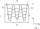
- FIG. 1 shown possible basic structure of a strain sensor according to the invention has an embedded in a substrate 3 electrical conductor 1.
- the electrical conductor 1 may also be applied to the substrate 3.
- a plurality of electrical conductors 1 may be provided in and / or on the substrate 3.
- the electrical conductor 1, in the embodiment of FIG. 1 a meander shape with long sections 1a and short sections 1b.
- the long sections 1a of the electrical conductor 1 extend in the embodiment shown approximately parallel to each other, ie at an angle of about 70 to 89 ° towards each other or an angle of about 91 to 120 ° away from each other, with changing installation direction.
- the long sections 1a can also run exactly parallel to one another and can all be arranged in the direction x.
- the short sections 1 b of the electrical conductor 1 are arranged almost perpendicular to the long sections 1 a and along a direction y with alternating orientation.
- the long sections 1a are also connected by cross struts of a thread-like bracing material 2.
- the bracing material 2 is essentially aligned perpendicular to the long sections 1a and parallel to the short sections 1b, so also along the direction y.
- a strain sensor with a meandering conductor according to FIG. 1 is particularly suitable for measuring strains along the in FIG. 1 illustrated direction x, ie along the direction in which the long sections 1a are oriented.
- measurements of bending expansions are also possible with such a strain sensor, which can be determined by a bending of the substrate 3 from a through the in FIG. 1 shown vectors x and y defined level out.
Landscapes
- Physics & Mathematics (AREA)
- General Physics & Mathematics (AREA)
- Measurement Of Length, Angles, Or The Like Using Electric Or Magnetic Means (AREA)
Applications Claiming Priority (1)
| Application Number | Priority Date | Filing Date | Title |
|---|---|---|---|
| DE102016107464.0A DE102016107464B3 (de) | 2016-04-22 | 2016-04-22 | Dehnungssensor und Verfahren zum Herstellen eines Dehnungssensors |
Publications (3)
| Publication Number | Publication Date |
|---|---|
| EP3236197A2 true EP3236197A2 (fr) | 2017-10-25 |
| EP3236197A3 EP3236197A3 (fr) | 2018-06-13 |
| EP3236197B1 EP3236197B1 (fr) | 2020-04-15 |
Family
ID=58632175
Family Applications (1)
| Application Number | Title | Priority Date | Filing Date |
|---|---|---|---|
| EP17166973.2A Active EP3236197B1 (fr) | 2016-04-22 | 2017-04-19 | Capteur d'expansion et son procédé de fabrication |
Country Status (2)
| Country | Link |
|---|---|
| EP (1) | EP3236197B1 (fr) |
| DE (1) | DE102016107464B3 (fr) |
Families Citing this family (3)
| Publication number | Priority date | Publication date | Assignee | Title |
|---|---|---|---|---|
| DE102018217973A1 (de) * | 2018-10-22 | 2020-04-23 | Fraunhofer-Gesellschaft zur Förderung der angewandten Forschung e.V. | Sensorsystem und Verfahren zum Erfassen von Verformungen eines Materials |
| CN109855775A (zh) * | 2019-01-25 | 2019-06-07 | 上海电力学院 | 一种微应力传感器的制备方法 |
| DE102019102908A1 (de) * | 2019-02-06 | 2020-08-06 | Fraunhofer-Gesellschaft zur Förderung der angewandten Forschung e.V. | Sensorvorrichtung für Druckmessungen von Fluiden, System für Druckmessungen von Fluiden |
Citations (2)
| Publication number | Priority date | Publication date | Assignee | Title |
|---|---|---|---|---|
| US20030056599A1 (en) | 2001-07-27 | 2003-03-27 | Van Schoor Marthinus Cornelius | Method and device for measuring strain using shape memory alloy materials |
| US6622558B2 (en) | 2000-11-30 | 2003-09-23 | Orbital Research Inc. | Method and sensor for detecting strain using shape memory alloys |
Family Cites Families (4)
| Publication number | Priority date | Publication date | Assignee | Title |
|---|---|---|---|---|
| JPH06258010A (ja) * | 1993-03-05 | 1994-09-16 | Tokin Corp | ひずみゲージ |
| JP3971961B2 (ja) * | 2002-06-10 | 2007-09-05 | 中央発條株式会社 | 超弾性合金箔とひずみセンサ及びそれらの製造方法 |
| JP4877950B2 (ja) * | 2006-07-31 | 2012-02-15 | 聰 島本 | 知的材料における形状回復力の制御方法及び知的材料 |
| US9499882B2 (en) * | 2009-01-09 | 2016-11-22 | United States Of America As Represented By The Administrator Of The National Aeronautics And Space Administration | Strain-detecting composite materials |
-
2016
- 2016-04-22 DE DE102016107464.0A patent/DE102016107464B3/de active Active
-
2017
- 2017-04-19 EP EP17166973.2A patent/EP3236197B1/fr active Active
Patent Citations (2)
| Publication number | Priority date | Publication date | Assignee | Title |
|---|---|---|---|---|
| US6622558B2 (en) | 2000-11-30 | 2003-09-23 | Orbital Research Inc. | Method and sensor for detecting strain using shape memory alloys |
| US20030056599A1 (en) | 2001-07-27 | 2003-03-27 | Van Schoor Marthinus Cornelius | Method and device for measuring strain using shape memory alloy materials |
Also Published As
| Publication number | Publication date |
|---|---|
| EP3236197B1 (fr) | 2020-04-15 |
| DE102016107464B3 (de) | 2017-08-10 |
| EP3236197A3 (fr) | 2018-06-13 |
Similar Documents
| Publication | Publication Date | Title |
|---|---|---|
| US6149742A (en) | Process for conditioning shape memory alloys | |
| DE102016107464B3 (de) | Dehnungssensor und Verfahren zum Herstellen eines Dehnungssensors | |
| Shariat et al. | Thermomechanical modelling of microstructurally graded shape memory alloys | |
| WO2012072428A1 (fr) | Verres métalliques à surface structurée et leur procédé de fabrication | |
| DE2516749B2 (de) | Verfahren zum Herstellen von Metallkörpern mit wiederholt reversiblem Gestaltwechselvermögen | |
| Shariat et al. | Hystoelastic deformation behaviour of geometrically graded NiTi shape memory alloys | |
| Manach et al. | Shear and tensile thermomechanical behavior of near equiatomic NiTi alloy | |
| Losertova et al. | Comparison of deformation behavior of 316L stainless steel and Ti6Al4V alloy applied in traumatology | |
| DE102018200635A1 (de) | Formgedächtnis-Aktoreinrichtung und Ventil basierend auf dieser Aktoreinrichtung | |
| Shariat et al. | Pseudoelastic behaviour of perforated NiTi shape memory plates under tension | |
| DE10155119A1 (de) | Aktuator | |
| DE69421671T2 (de) | Wiederkonfigurierbarer faseroptischer sensor | |
| WO2012076247A2 (fr) | Système de capteurs ou capteur permettant la détection de grandeurs de mesure mécaniques ou thermiques ou d'états du système | |
| WO2019081712A1 (fr) | Dispositif de mesure d'allongement | |
| KR101957481B1 (ko) | 강재의 성형성 증가방법 | |
| DE102009048625B4 (de) | Kraftfahrzeug mit Dämpfervorrichtung, Dämpfervorrichtung sowie Bauteil für Dämpfvorrichtung | |
| WO2011066816A1 (fr) | Composant, procédé d'introduction d'informations dans un composant et procédé de détermination d'un historique de sollicitation d'un composant | |
| DE102011015081B4 (de) | Sensorfaser sowie Sensorfaseranordnung | |
| DE4228566B4 (de) | Verfahren zum Biegeumformen verformbarer Körper | |
| DE10246865B4 (de) | Strukturbauteil für ein Kraftfahrzeug | |
| Yoo et al. | An experimental study of the two-way shape memory effect in a NiTi tubular actuator | |
| EP1550353B1 (fr) | Corps composite et procede de fabrication dudit corps | |
| DE102006018896B3 (de) | Ortsselektive Veränderung der Materialeigenschaft kaltverformter elektrischer Klemmen durch Berücksichtigung der variablen Rekristallisationstemperatur | |
| DE102015209683A1 (de) | Verfahren zum Herstellen eines Sensors und Sensor | |
| Shariat | Experimental investigation of heterogeneous strain fields created in metallic materials |
Legal Events
| Date | Code | Title | Description |
|---|---|---|---|
| PUAI | Public reference made under article 153(3) epc to a published international application that has entered the european phase |
Free format text: ORIGINAL CODE: 0009012 |
|
| STAA | Information on the status of an ep patent application or granted ep patent |
Free format text: STATUS: THE APPLICATION HAS BEEN PUBLISHED |
|
| AK | Designated contracting states |
Kind code of ref document: A2 Designated state(s): AL AT BE BG CH CY CZ DE DK EE ES FI FR GB GR HR HU IE IS IT LI LT LU LV MC MK MT NL NO PL PT RO RS SE SI SK SM TR |
|
| AX | Request for extension of the european patent |
Extension state: BA ME |
|
| PUAL | Search report despatched |
Free format text: ORIGINAL CODE: 0009013 |
|
| AK | Designated contracting states |
Kind code of ref document: A3 Designated state(s): AL AT BE BG CH CY CZ DE DK EE ES FI FR GB GR HR HU IE IS IT LI LT LU LV MC MK MT NL NO PL PT RO RS SE SI SK SM TR |
|
| AX | Request for extension of the european patent |
Extension state: BA ME |
|
| RIC1 | Information provided on ipc code assigned before grant |
Ipc: G01B 7/16 20060101AFI20180508BHEP |
|
| STAA | Information on the status of an ep patent application or granted ep patent |
Free format text: STATUS: REQUEST FOR EXAMINATION WAS MADE |
|
| 17P | Request for examination filed |
Effective date: 20180919 |
|
| RBV | Designated contracting states (corrected) |
Designated state(s): AL AT BE BG CH CY CZ DE DK EE ES FI FR GB GR HR HU IE IS IT LI LT LU LV MC MK MT NL NO PL PT RO RS SE SI SK SM TR |
|
| STAA | Information on the status of an ep patent application or granted ep patent |
Free format text: STATUS: EXAMINATION IS IN PROGRESS |
|
| 17Q | First examination report despatched |
Effective date: 20190401 |
|
| GRAP | Despatch of communication of intention to grant a patent |
Free format text: ORIGINAL CODE: EPIDOSNIGR1 |
|
| STAA | Information on the status of an ep patent application or granted ep patent |
Free format text: STATUS: GRANT OF PATENT IS INTENDED |
|
| RIC1 | Information provided on ipc code assigned before grant |
Ipc: G01L 1/22 20060101ALN20200121BHEP Ipc: G01B 7/16 20060101AFI20200121BHEP Ipc: G01B 1/00 20060101ALI20200121BHEP |
|
| GRAS | Grant fee paid |
Free format text: ORIGINAL CODE: EPIDOSNIGR3 |
|
| INTG | Intention to grant announced |
Effective date: 20200213 |
|
| GRAA | (expected) grant |
Free format text: ORIGINAL CODE: 0009210 |
|
| STAA | Information on the status of an ep patent application or granted ep patent |
Free format text: STATUS: THE PATENT HAS BEEN GRANTED |
|
| AK | Designated contracting states |
Kind code of ref document: B1 Designated state(s): AL AT BE BG CH CY CZ DE DK EE ES FI FR GB GR HR HU IE IS IT LI LT LU LV MC MK MT NL NO PL PT RO RS SE SI SK SM TR |
|
| REG | Reference to a national code |
Ref country code: CH Ref legal event code: EP |
|
| REG | Reference to a national code |
Ref country code: DE Ref legal event code: R096 Ref document number: 502017004704 Country of ref document: DE |
|
| REG | Reference to a national code |
Ref country code: IE Ref legal event code: FG4D Free format text: LANGUAGE OF EP DOCUMENT: GERMAN |
|
| REG | Reference to a national code |
Ref country code: AT Ref legal event code: REF Ref document number: 1257832 Country of ref document: AT Kind code of ref document: T Effective date: 20200515 |
|
| REG | Reference to a national code |
Ref country code: NL Ref legal event code: MP Effective date: 20200415 |
|
| REG | Reference to a national code |
Ref country code: LT Ref legal event code: MG4D |
|
| PG25 | Lapsed in a contracting state [announced via postgrant information from national office to epo] |
Ref country code: LT Free format text: LAPSE BECAUSE OF FAILURE TO SUBMIT A TRANSLATION OF THE DESCRIPTION OR TO PAY THE FEE WITHIN THE PRESCRIBED TIME-LIMIT Effective date: 20200415 Ref country code: NL Free format text: LAPSE BECAUSE OF FAILURE TO SUBMIT A TRANSLATION OF THE DESCRIPTION OR TO PAY THE FEE WITHIN THE PRESCRIBED TIME-LIMIT Effective date: 20200415 Ref country code: PT Free format text: LAPSE BECAUSE OF FAILURE TO SUBMIT A TRANSLATION OF THE DESCRIPTION OR TO PAY THE FEE WITHIN THE PRESCRIBED TIME-LIMIT Effective date: 20200817 Ref country code: FI Free format text: LAPSE BECAUSE OF FAILURE TO SUBMIT A TRANSLATION OF THE DESCRIPTION OR TO PAY THE FEE WITHIN THE PRESCRIBED TIME-LIMIT Effective date: 20200415 Ref country code: GR Free format text: LAPSE BECAUSE OF FAILURE TO SUBMIT A TRANSLATION OF THE DESCRIPTION OR TO PAY THE FEE WITHIN THE PRESCRIBED TIME-LIMIT Effective date: 20200716 Ref country code: NO Free format text: LAPSE BECAUSE OF FAILURE TO SUBMIT A TRANSLATION OF THE DESCRIPTION OR TO PAY THE FEE WITHIN THE PRESCRIBED TIME-LIMIT Effective date: 20200715 Ref country code: SE Free format text: LAPSE BECAUSE OF FAILURE TO SUBMIT A TRANSLATION OF THE DESCRIPTION OR TO PAY THE FEE WITHIN THE PRESCRIBED TIME-LIMIT Effective date: 20200415 Ref country code: IS Free format text: LAPSE BECAUSE OF FAILURE TO SUBMIT A TRANSLATION OF THE DESCRIPTION OR TO PAY THE FEE WITHIN THE PRESCRIBED TIME-LIMIT Effective date: 20200815 |
|
| PG25 | Lapsed in a contracting state [announced via postgrant information from national office to epo] |
Ref country code: RS Free format text: LAPSE BECAUSE OF FAILURE TO SUBMIT A TRANSLATION OF THE DESCRIPTION OR TO PAY THE FEE WITHIN THE PRESCRIBED TIME-LIMIT Effective date: 20200415 Ref country code: HR Free format text: LAPSE BECAUSE OF FAILURE TO SUBMIT A TRANSLATION OF THE DESCRIPTION OR TO PAY THE FEE WITHIN THE PRESCRIBED TIME-LIMIT Effective date: 20200415 Ref country code: BG Free format text: LAPSE BECAUSE OF FAILURE TO SUBMIT A TRANSLATION OF THE DESCRIPTION OR TO PAY THE FEE WITHIN THE PRESCRIBED TIME-LIMIT Effective date: 20200715 Ref country code: LV Free format text: LAPSE BECAUSE OF FAILURE TO SUBMIT A TRANSLATION OF THE DESCRIPTION OR TO PAY THE FEE WITHIN THE PRESCRIBED TIME-LIMIT Effective date: 20200415 |
|
| PG25 | Lapsed in a contracting state [announced via postgrant information from national office to epo] |
Ref country code: AL Free format text: LAPSE BECAUSE OF FAILURE TO SUBMIT A TRANSLATION OF THE DESCRIPTION OR TO PAY THE FEE WITHIN THE PRESCRIBED TIME-LIMIT Effective date: 20200415 |
|
| REG | Reference to a national code |
Ref country code: DE Ref legal event code: R097 Ref document number: 502017004704 Country of ref document: DE |
|
| PG25 | Lapsed in a contracting state [announced via postgrant information from national office to epo] |
Ref country code: IT Free format text: LAPSE BECAUSE OF FAILURE TO SUBMIT A TRANSLATION OF THE DESCRIPTION OR TO PAY THE FEE WITHIN THE PRESCRIBED TIME-LIMIT Effective date: 20200415 Ref country code: ES Free format text: LAPSE BECAUSE OF FAILURE TO SUBMIT A TRANSLATION OF THE DESCRIPTION OR TO PAY THE FEE WITHIN THE PRESCRIBED TIME-LIMIT Effective date: 20200415 Ref country code: RO Free format text: LAPSE BECAUSE OF FAILURE TO SUBMIT A TRANSLATION OF THE DESCRIPTION OR TO PAY THE FEE WITHIN THE PRESCRIBED TIME-LIMIT Effective date: 20200415 Ref country code: CZ Free format text: LAPSE BECAUSE OF FAILURE TO SUBMIT A TRANSLATION OF THE DESCRIPTION OR TO PAY THE FEE WITHIN THE PRESCRIBED TIME-LIMIT Effective date: 20200415 Ref country code: EE Free format text: LAPSE BECAUSE OF FAILURE TO SUBMIT A TRANSLATION OF THE DESCRIPTION OR TO PAY THE FEE WITHIN THE PRESCRIBED TIME-LIMIT Effective date: 20200415 Ref country code: DK Free format text: LAPSE BECAUSE OF FAILURE TO SUBMIT A TRANSLATION OF THE DESCRIPTION OR TO PAY THE FEE WITHIN THE PRESCRIBED TIME-LIMIT Effective date: 20200415 Ref country code: SM Free format text: LAPSE BECAUSE OF FAILURE TO SUBMIT A TRANSLATION OF THE DESCRIPTION OR TO PAY THE FEE WITHIN THE PRESCRIBED TIME-LIMIT Effective date: 20200415 Ref country code: MC Free format text: LAPSE BECAUSE OF FAILURE TO SUBMIT A TRANSLATION OF THE DESCRIPTION OR TO PAY THE FEE WITHIN THE PRESCRIBED TIME-LIMIT Effective date: 20200415 Ref country code: LU Free format text: LAPSE BECAUSE OF NON-PAYMENT OF DUE FEES Effective date: 20200419 |
|
| REG | Reference to a national code |
Ref country code: BE Ref legal event code: MM Effective date: 20200430 |
|
| PLBE | No opposition filed within time limit |
Free format text: ORIGINAL CODE: 0009261 |
|
| STAA | Information on the status of an ep patent application or granted ep patent |
Free format text: STATUS: NO OPPOSITION FILED WITHIN TIME LIMIT |
|
| PG25 | Lapsed in a contracting state [announced via postgrant information from national office to epo] |
Ref country code: SK Free format text: LAPSE BECAUSE OF FAILURE TO SUBMIT A TRANSLATION OF THE DESCRIPTION OR TO PAY THE FEE WITHIN THE PRESCRIBED TIME-LIMIT Effective date: 20200415 Ref country code: PL Free format text: LAPSE BECAUSE OF FAILURE TO SUBMIT A TRANSLATION OF THE DESCRIPTION OR TO PAY THE FEE WITHIN THE PRESCRIBED TIME-LIMIT Effective date: 20200415 Ref country code: BE Free format text: LAPSE BECAUSE OF NON-PAYMENT OF DUE FEES Effective date: 20200430 |
|
| 26N | No opposition filed |
Effective date: 20210118 |
|
| PG25 | Lapsed in a contracting state [announced via postgrant information from national office to epo] |
Ref country code: IE Free format text: LAPSE BECAUSE OF NON-PAYMENT OF DUE FEES Effective date: 20200419 |
|
| PG25 | Lapsed in a contracting state [announced via postgrant information from national office to epo] |
Ref country code: SI Free format text: LAPSE BECAUSE OF FAILURE TO SUBMIT A TRANSLATION OF THE DESCRIPTION OR TO PAY THE FEE WITHIN THE PRESCRIBED TIME-LIMIT Effective date: 20200415 |
|
| PG25 | Lapsed in a contracting state [announced via postgrant information from national office to epo] |
Ref country code: TR Free format text: LAPSE BECAUSE OF FAILURE TO SUBMIT A TRANSLATION OF THE DESCRIPTION OR TO PAY THE FEE WITHIN THE PRESCRIBED TIME-LIMIT Effective date: 20200415 Ref country code: MT Free format text: LAPSE BECAUSE OF FAILURE TO SUBMIT A TRANSLATION OF THE DESCRIPTION OR TO PAY THE FEE WITHIN THE PRESCRIBED TIME-LIMIT Effective date: 20200415 Ref country code: CY Free format text: LAPSE BECAUSE OF FAILURE TO SUBMIT A TRANSLATION OF THE DESCRIPTION OR TO PAY THE FEE WITHIN THE PRESCRIBED TIME-LIMIT Effective date: 20200415 |
|
| PG25 | Lapsed in a contracting state [announced via postgrant information from national office to epo] |
Ref country code: MK Free format text: LAPSE BECAUSE OF FAILURE TO SUBMIT A TRANSLATION OF THE DESCRIPTION OR TO PAY THE FEE WITHIN THE PRESCRIBED TIME-LIMIT Effective date: 20200415 |
|
| PGFP | Annual fee paid to national office [announced via postgrant information from national office to epo] |
Ref country code: DE Payment date: 20250210 Year of fee payment: 9 |
|
| PGFP | Annual fee paid to national office [announced via postgrant information from national office to epo] |
Ref country code: GB Payment date: 20250423 Year of fee payment: 9 |
|
| PGFP | Annual fee paid to national office [announced via postgrant information from national office to epo] |
Ref country code: FR Payment date: 20250424 Year of fee payment: 9 |
|
| PGFP | Annual fee paid to national office [announced via postgrant information from national office to epo] |
Ref country code: CH Payment date: 20250501 Year of fee payment: 9 |
|
| PGFP | Annual fee paid to national office [announced via postgrant information from national office to epo] |
Ref country code: AT Payment date: 20250416 Year of fee payment: 9 |