EP3236201B1 - Laser rotatif destiné à déterminer la perpendicularité de deux parties de machine - Google Patents
Laser rotatif destiné à déterminer la perpendicularité de deux parties de machine Download PDFInfo
- Publication number
- EP3236201B1 EP3236201B1 EP17166160.6A EP17166160A EP3236201B1 EP 3236201 B1 EP3236201 B1 EP 3236201B1 EP 17166160 A EP17166160 A EP 17166160A EP 3236201 B1 EP3236201 B1 EP 3236201B1
- Authority
- EP
- European Patent Office
- Prior art keywords
- laser beam
- reference plane
- rotation
- axis
- plane
- Prior art date
- Legal status (The legal status is an assumption and is not a legal conclusion. Google has not performed a legal analysis and makes no representation as to the accuracy of the status listed.)
- Active
Links
Images

Classifications
-
- G—PHYSICS
- G01—MEASURING; TESTING
- G01B—MEASURING LENGTH, THICKNESS OR SIMILAR LINEAR DIMENSIONS; MEASURING ANGLES; MEASURING AREAS; MEASURING IRREGULARITIES OF SURFACES OR CONTOURS
- G01B11/00—Measuring arrangements characterised by the use of optical techniques
- G01B11/26—Measuring arrangements characterised by the use of optical techniques for measuring angles or tapers; for testing the alignment of axes
- G01B11/27—Measuring arrangements characterised by the use of optical techniques for measuring angles or tapers; for testing the alignment of axes for testing the alignment of axes
-
- G—PHYSICS
- G01—MEASURING; TESTING
- G01B—MEASURING LENGTH, THICKNESS OR SIMILAR LINEAR DIMENSIONS; MEASURING ANGLES; MEASURING AREAS; MEASURING IRREGULARITIES OF SURFACES OR CONTOURS
- G01B11/00—Measuring arrangements characterised by the use of optical techniques
- G01B11/26—Measuring arrangements characterised by the use of optical techniques for measuring angles or tapers; for testing the alignment of axes
- G01B11/27—Measuring arrangements characterised by the use of optical techniques for measuring angles or tapers; for testing the alignment of axes for testing the alignment of axes
- G01B11/272—Measuring arrangements characterised by the use of optical techniques for measuring angles or tapers; for testing the alignment of axes for testing the alignment of axes using photoelectric detection means
-
- G—PHYSICS
- G01—MEASURING; TESTING
- G01C—MEASURING DISTANCES, LEVELS OR BEARINGS; SURVEYING; NAVIGATION; GYROSCOPIC INSTRUMENTS; PHOTOGRAMMETRY OR VIDEOGRAMMETRY
- G01C1/00—Measuring angles
-
- G—PHYSICS
- G01—MEASURING; TESTING
- G01C—MEASURING DISTANCES, LEVELS OR BEARINGS; SURVEYING; NAVIGATION; GYROSCOPIC INSTRUMENTS; PHOTOGRAMMETRY OR VIDEOGRAMMETRY
- G01C15/00—Surveying instruments or accessories not provided for in groups G01C1/00 - G01C13/00
- G01C15/002—Active optical surveying means
Definitions
- the invention relates to a rotating laser with a laser device for generating a laser beam which is pulsed by a control device at a pulse frequency and which, as a pulse train, is partially deflected as a pulse train from a direction parallel to the rotational axis as a rotating laser beam into a rotational plane running perpendicular to the rotational axis and partially emerges as an axial laser beam directed parallel to the axis of rotation.
- the invention also relates to a method for determining the perpendicularity of a machine part or the movement of a machine part relative to a reference plane using such a rotating laser.
- Rotating lasers are from the DE 43 41 578 A1 and the DE 10 2008 035480 A1 known. They are used to measure the relative position of various machine parts to one another.
- a rotating laser When measuring the perpendicularity of a machine part or the movement of a machine part in relation to a reference plane, for example the direction of displacement of a tool spindle relative to a machine table, a rotating laser is set up on the machine table.
- Several measuring receivers are set up at a distance from the rotating laser, which are able to determine the vertical distance of a point of light impinging on the measuring field of the measuring receiver from the reference plane.
- a laser beam device of the rotary laser which generates a rotating laser beam
- the plane of rotation of the rotating laser beam can be brought into a plane parallel to the reference plane, so that the axis of rotation is perpendicular to the reference axis.
- An axial laser beam runs optimally in the axis of rotation, but often at a certain angle of inclination to it. Since the axial laser beam is generated by the same laser that also generates the rotating laser beam, the axial laser beam generates a light spot rotating in the measuring plane of a measuring receiver. To increase the sensitivity of the measuring receiver, the laser beam is generated as a pulse train.
- a pulsed laser beam therefore hits both the measuring receiver located in the reference plane and the measuring receiver that can be displaced perpendicularly to the reference plane to determine the position of the machine part. Measurement errors can occur if the measurement receivers are positioned in such a way that they are rarely hit by pulses.
- the EP 2 626 722 A1 describes an optoelectric sensor in the form of a rotating laser.
- a rotating laser beam rotating in a plane of rotation is to be reflected by an object.
- the spatial position of the object is to be determined based on the angle of the laser beam and the time it takes for the light to travel.
- the laser beam consists of a pseudo-random pulse sequence.
- the invention is based on the object of proposing measures to further develop the rotary laser mentioned at the outset or a method for measuring the perpendicularity of machine parts or for determining the movement of a machine part in a manner that is advantageous in terms of use.
- the control device controls the laser in such a way that it emits successive pulse sequences.
- the pulses of the pulse trains can have a pulse frequency that is several kHz, in particular 16 kHz.
- the individual pulse trains have a time Pulse train length less than one second.
- the successive pulse sequences are phase-shifted by a phase angle.
- the phase angle can be any angle within a full circle.
- the control device is able to actuate servomotors, which are able to swivel the laser beam device, which is arranged cardanically inside the housing of the rotary laser, about a pivot point. Additional leveling elements can be provided in order to be able to bring the rotating laser beam into a horizontal plane.
- the control device keeps the laser device in a continuously regulating position in which the plane of rotation runs parallel to the reference plane.
- the measuring receivers are in a data transmission connection with the control device, for example via infrared light.
- the rotating laser is first brought to a stationary position in relation to the reference plane.
- the direction of displacement of this measuring receiver can vary from the axis of rotation, which is perpendicular to the reference plane runs, deviate. These deviations are determined using the measuring receiver. These are deviations in one direction in a plane parallel to the horizontal plane.
- the laser of the laser beam device generates the above-mentioned pulse sequences, for example with a pulse frequency of several kilohertz. These pulse sequences hit the measuring field of the measuring receiver, which can be moved in the axial direction, in immediate succession, so that the evaluation electronics there can distinguish between dark and light phases.
- the position of a laser beam point on the measuring surface can thus be determined by means of this measuring receiver, and thus its spatial position in relation to the measuring receiver.
- the rotational movement of the deflection element which can be a rotating pentaprism, generates points of light that move on a circular or elliptical path across the measuring field of the measuring receiver.
- the measuring receiver or its evaluation electronics is able to determine the center of area of this elliptical or circular path, which corresponds to the position of the axis of rotation. Since the axial laser beam and the rotating laser beam are decoupled from the same laser beam, the rotating laser beam is also pulsed. Angular areas with a dark phase and angular areas with a light phase are thus generated during the rotation of the rotating laser beam.
- the pulse sequence is shifted by the control device at predetermined times by a phase angle in each case, the predetermined times corresponding to less than one second, so that the pulse sequences are phase-shifted several times in one second by phase angles that differ from one another and lie between 0 ⁇ and 2 ⁇ . This is preferably done using a random number generator that calculates the respective amount of the phase shift specifies.
- the control device is thus adequately able to keep the laser device in a position in which the rotating laser beam rotates in a plane parallel to the reference plane, so that the axis of rotation is exactly perpendicular to the reference plane, by means of permanent regulation.
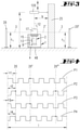
- the figure 1 shows a first example of use of a rotating laser 1 in combination with a plurality of measurement receivers 20, 20', 20".
- a machine has a machine table that defines a reference plane 48 .
- a machine part 26 can be moved in a direction perpendicular to the reference plane 48 relative to this table, ie the reference plane 48 .
- the machine part 26 can be the spindle of a machine tool, for example a tool spindle, with which a milling cutter can be driven, with which workpieces that are fastened on the machine table can be machined.
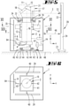
- a measuring receiver 120 in the figure 2 is shown in the plan view of the measuring field 22.
- a head of the rotary laser 1 forms a deflection element 17, with which a laser beam 16 generated by a laser beam device is divided and deflected.
- the laser beam 16 generated within the rotary laser 1 is deflected by the deflection element 17, which can have a pentaprism, in a direction transverse to the axis of rotation 11 of the deflection element 17.
- a laser beam 3 rotating about the axis of rotation 11 in a plane of rotation 3' is generated.
- Another part of the laser beam 16 exits the head 17 essentially without deflection in the axial direction. It preferably runs exactly within the axis of rotation 11.
- the axial laser beam 12 can have a slight radial offset from the axis of rotation 11 of a few micrometers, so that the laser beam 12 circulates on a circular path around the axis of rotation 11 on the measuring field 122.
- the rotating laser beam 3 runs over the measuring fields 22 of the measuring receivers 20, 20', 20".
- the measuring receivers 20, 20′, 20′′ are arranged in the reference plane 48 in such a way that they lie on the corner points of a triangle, preferably on the corner points of an isosceles triangle, and the rotating laser 1 lies within this triangle.
- FIG. 3 illustrated embodiment corresponds essentially to that in FIGS Figures 1 and 2 illustrated embodiment, but here the perpendicularity of a machine part 25 relative to the reference plane 48 is to be determined.
- a measuring receiver 120 is shifted in a direction transverse to the reference plane 48 .
- the measurement receiver 120 is guided along the machine part 25 in order to measure the radial distance b of the machine part 25 from the axial laser beam 12 or from the axis of rotation 11 at a large number of axial distances a from the reference plane 48 .
- a control device 9 of the rotating laser 1 is able to receive values from the measuring receivers 20, 20', 20" that correspond to the vertical positions c1, c2 at which the rotating laser beam 3 touches the measuring field 22 of the respective measuring receiver 20, 20 ', 20" hits. These are the axial distances, relative to the axis of rotation 11, of the points of impact of the laser beam 3 on the measuring fields 22 from the reference plane 48.
- the laser beam device 2 gimballed within the housing of the rotating laser 1 can be brought into such a position by means of servomotors 6 , 7 that the plane of rotation of the rotating laser beam 3 runs parallel to the reference plane 48 .
- the laser beam device 2 and the deflection element 17, which is fixedly but rotatably connected to the laser beam device 2 are slightly changed in their inclined position.
- the measurement of perpendicularity begins with this alignment of the plane of rotation 3 ′ in a plane parallel to the reference plane 48 , so that the axis of rotation 11 runs perpendicular to the reference plane 48 . Then the perpendicularity of the machine part 25 or 26 is measured by a vertical displacement of the measuring receiver 120 in the direction of the double arrows in FIG figures 1 and 3 .
- the control device 9 controls the laser of the laser device 2, so that this in the figure 4 illustrated pulse sequences P 1 , P 2 , P 3 , P 4 emits in immediate succession. The consequence of this is that both the rotating laser beam 3 and the axial laser beam 12 are pulsed.
- the one in the figure 4 pulse sequences P 1 to P 4 shown have the same pulse frequency of, for example, 16 kHz.
- the rotational frequency of the rotating laser beam 3 is in the single-digit Hertz range, but can also be higher.
- the rotation frequency and the pulse frequency are not linked to one another, so that there can be situations in which the pulse frequency is an integer multiple of the rotation frequency, or that no "rotating" but “stationary” pulses are generated at a fixed azimuthal position in relation to the axis of rotation 11 will.
- the phase-shifted pulse sequences shown ensure that there are no permanently "standing" pulse gaps. The consequence of this is that the measuring receivers 20, 20', 20'' can be arranged at any desired locations around the rotating laser 1, since stationary pulse gaps are avoided due to the phase shifts ⁇ 1 to ⁇ 4 .
- the positions of the measuring receivers 20, 20', 20" are shown as dashed lines.
- the pulse sequence P 1 which is offset by the phase angle ⁇ 1 with respect to an arbitrary phase zero point, the measuring receiver 20 and the measuring receiver 20" are in a pulse gap, whereas the measuring receiver 20' is struck by a pulse.
- the pulse sequence P 2 which immediately follows the pulse sequence P1 but is phase-shifted with a different phase angle ⁇ 2 compared to the phase zero point, the measuring receiver 20 'is in a pulse gap, whereas the measuring receivers 20, 20 "can receive a pulse.
- phase shift angles ⁇ 1 to ⁇ 4 of the successive pulse sequences P 1 to P 4 which each have the same pulse sequence length L, can be generated randomly. For example, this is done with (pseudo)random numbers generated by the control device 9 .
- the pulse train length L is less than one second. It is preferably in the range between half a second and a twentieth of a second, so that the pulse frequency is at least 10 times, preferably at least 50 times or 100 times the phase position change frequency.
- a pulsating point of light 123 moves on the measuring field 122 on a circular path or elliptical path around the axis of rotation 11, with the radius being able to be in the micrometer range.
- An evaluation device of the measuring receiver 20 is able to determine the center of area of this circular path or elliptical path.
- the pulsing of the laser beam increases the sensitivity of the measuring receiver 120 since every pulse and every pulse gap is received there.
- the light-dark differences generated on the measuring field 122 during the pulses can be determined via synchronization with the control device 9 and thus the position of the light spot 123 in the area of the measuring field 122. From this, the position of the measuring receiver 120 in the horizontal direction in relation to the axis of rotation can be determined 11 determine. This value forms the basis for determining the distance b in figure 3 or the position of the machine part 26 in a plane parallel to the reference plane 48 relative to the axis of rotation 11.
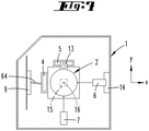
- the rotary laser shown schematically has a housing 1 which has a bottom and a top and four vertical sides when the housing 1 is set up on a horizontal surface 48 by means of mounting points 43 .
- the bottom surface has a foot 8 which forms a fastening section with which the bottom surface can also be fastened to a vertical surface.
- fastening means for example internal threads 44, can be provided with which the foot 8 or the fastening section can be fastened to a tripod.
- the fastening section 8 forms a round rotary disc which is connected to the housing 1 via a rotary bearing 37 .
- the rotary bearing 37 can be a ball bearing which has a rotary axis 10 which is essentially a vertical axis 1 when the rotary laser is in the standing position.
- the fastening section 8 can have a peripheral toothing 45 into which the teeth of a gear wheel 36 which is driven in rotation by a rotary drive 47 engage.
- the rotary drive 47 is preferably a stepper motor, so that the housing 1 can be rotated about the axis of rotation 10 into a freely selectable angular position, with the fastening section 8 remaining firmly connected to the base, for example the horizontal surface 48 or a tripod.
- a cardanic suspension for a laser beam device 2 is located inside the housing 1.
- a cardanic suspension 39 fixed to the housing supports a gimbal ring body 41, which can be pivoted about a joint axis 40.
- the joint axis 40 extends in the y-direction running in a horizontal plane.
- the gimbal body 41 can be rotated about the Y-axis by means of a servomotor 6 be pivoted in order to adjust the inclined position of a central axis 11 of the laser beam device 2 .
- the laser beam device 2 is connected to the gimbal body 41 via hinge axes 42 extending in the horizontal X-direction.
- Another actuator 7 is capable of pivoting the laser beam device 2 about the X-axis.
- the gimbals 39 to 42 thus form a pivot point around which the inclined position of the laser beam device 2 or its axis 11 is aligned in such a way that it is perpendicular to a horizontal plane.
- the laser beam device 2 carries a pivot bearing 38, via which a head 17 is rotatably connected to the laser beam device 2, but is axially and tilt-fixed.
- the axis of the laser beam device 2 corresponds to the axis of rotation 11 about which the head 17 can rotate relative to the laser beam device 2 .
- a rotary drive 19 is provided, which can have magnets 33 and coils 34, for example, in order to rotate the head 17 around the laser beam device 2 in such a way that a laser beam 3 exiting the head 17 at right angles to the axis of rotation 11 is in a plane of rotation perpendicular to the axis of rotation 11 rotates.
- the laser beam device 2 has a laser 15, which can be a semiconductor laser. This is fixed in place on the housing 1 and generates a laser beam 16 which is guided to an emission surface 15 via an optical waveguide 64 . From this emerges a laser beam 16 aligned coaxially to the axis of rotation, which passes through the rotary bearing 38 and enters a pentaprism 18 assigned to the head 17, in which the laser beam 16 or part of the laser beam 16 is deflected by 90° by multiple reflection. For fine adjustment of A wedge plate 32 is provided so that the laser beam 3 is perpendicular to the laser beam 16 .
- Another portion of the laser beam 16 passes through the pentaprism 18 essentially in a straight line. Refraction effects are compensated by a compensating prism 31 in such a way that an axial laser beam 12 propagates parallel to the axis of rotation 11 and preferably in the axis of rotation 11 .
- the axial laser beam 12 is aligned in such a way that it runs as perpendicularly as possible to the plane of rotation of the rotating laser beam 3 .
- first leveling means 4 which is a spirit level which emits an electrical signal which changes when the inclination position 4 of the spirit level is changed.
- the inclination of the laser beam device 2 about the x-direction can be determined with the bubble level 4 .
- the inclined position of the laser beam device 2 relative to the Y-axis can be determined with a second leveling means 5, which is also formed by a spirit level.
- a control device 9 is provided, which can be a microcontroller that sits on a printed circuit board 35 .
- the control device 9 obtains information about the inclination position of the laser beam device 2 and in particular about the angular position of the axis of rotation 11 relative to a vertical axis.
- the control device 9 is able to adjust the laser beam device 2 in such a way that the axis of rotation 11 or the direction of the axial laser beam 12 runs in a vertical direction.
Landscapes
- Physics & Mathematics (AREA)
- General Physics & Mathematics (AREA)
- Engineering & Computer Science (AREA)
- Radar, Positioning & Navigation (AREA)
- Remote Sensing (AREA)
- Length Measuring Devices By Optical Means (AREA)
Claims (13)
- Laser rotatif (1) avec une tête réalisée sous la forme d'un organe de déviation (17), avec un dispositif de commande (9) et avec un dispositif laser (2), dans lequel le dispositif laser (2) est conçu pour générer un faisceau laser (16) pulsé à une fréquence d'impulsion par le dispositif de commande (9), dans lequel l'organe de déviation (17) est agencé de manière que le faisceau laser (16) sorte sous la forme d'une séquence d'impulsions (P1, P2, P3, P4) de l'organe de déviation (17) tournant autour d'un axe de rotation (4), en étant pour partie dévié par l'organe de déviation (17) d'une direction parallèle à l'axe de rotation (11) dans un plan de rotation (3') s'étendant perpendiculairement à l'axe de rotation (11) en tant que faisceau laser rotatif (3) et en étant pour partie dirigé parallèlement à l'axe de rotation (11) en tant que faisceau laser axial (12) de sorte que le faisceau laser axial (12) peut sortir de la tête du laser rotatif (1) sensiblement sans déviation dans la direction axiale, dans lequel le dispositif de commande (9) est réglé de manière que la séquence d'impulsions (P1, P2, P3, P4) soit déphasée plusieurs fois dans une seconde par des angles de phase (ϕ1, ϕ2, ϕ3, ϕ4) différents les uns des autres et compris entre 0 π et 2 π.
- Procédé pour déterminer la perpendicularité d'une partie de machine (25) 15 par rapport à un plan de référence (48), comprenant les étapes suivantes :- agencement fixe d'un laser rotatif (1) selon la revendication 1 par rapport au plan de référence (48) ;- agencement fixe d'une pluralité de récepteurs de mesure (20, 20', 20") par rapport au plan de référence (48) ;- orienter le plan de rotation (3') parallèlement au plan de référence (48) au moyen du faisceau laser rotatif (3) frappant les récepteurs de mesure (20, 20', 20") ;- utiliser un autre récepteur de mesure (120) à différentes distances (a) du plan de référence (48) pour déterminer la position respective de la partie de machine (25, 26) par rapport à l'axe de rotation (11) du rayon laser axial (12) à chaque fois dans un plan parallèle au plan de référence (48) ;- générer une séquence d'impulsions (P1, P2, P3, P4) d'impulsions de faisceau laser ;- décaler la séquence d'impulsions (P1, P2, P3, P4) plusieurs fois par seconde d'un angle de phase (ϕ1, ϕ2, ϕ3) qui se situe entre 0 π et 2 π ;- détecter de manière simultanée la position du faisceau laser rotatif (3) et la position du faisceau laser axial (12) avec les récepteurs de mesure (20, 20', 20", 120) .
- Procédé pour déterminer le mouvement d'une partie de machine (26) par rapport à un plan de référence (48), comprenant les étapes suivantes :- agencement fixe d'un laser rotatif (1) selon la revendication 1 par rapport au plan de référence (48) ;- agencement fixe de plusieurs récepteurs de mesure (20, 20', 20") par rapport au plan de référence (48) ;- orienter le plan de rotation (3') parallèlement au plan de référence (48) au moyen du faisceau laser rotatif (3) frappant les récepteurs de mesure (20, 20', 20") ;- utiliser un autre récepteur de mesure (120) à différentes distances (a) du plan de référence (48) pour déterminer la position respective de la partie de machine (25, 26) par rapport à l'axe de rotation (11) du rayon laser axial (12) à chaque fois dans un plan parallèle au plan de référence (48) ;- générer une séquence d'impulsions (P1, P2, P3, P4) d'impulsions de faisceau laser ;- décaler la séquence d'impulsions (P1, P2, P3, P4) plusieurs fois par seconde d'un angle de phase (ϕ1, ϕ2, ϕ3) qui se situe entre 0 π et 2 π ;- détecter de manière simultanée la position du faisceau laser rotatif (3) et la position du faisceau laser axial (12) avec les récepteurs de mesure (20, 20', 20", 120) .
- Dispositif selon la revendication 1, caractérisé par un récepteur de mesure (120) qui est déplaçable perpendiculairement au plan de référence (48) et qui est capable à partir d'un point lumineux pulsé (123) tournant à une faible distance autour de l'axe de rotation (11) sur une trajectoire circulaire ou elliptique sur une surface de détection (122) du récepteur de mesure (120), de déterminer le point central de la surface de la trajectoire circulaire ou elliptique.
- Dispositif selon la revendication 1 ou 4, caractérisé en ce que la fréquence d'impulsion est au moins 10 fois, au moins 50 fois ou au moins 100 fois plus élevée que le nombre de déphasages par seconde.
- Dispositif selon la revendication 1, 4 ou 5, caractérisé en ce que les séquences d'impulsions déphasées (P1, P2, P3, P4) ont chacune la même longueur temporelle d'impulsion (L) .
- Dispositif selon la revendication 1, 4, 5 ou 6, caractérisé en ce que la valeur du déphasage (ϕ1, ϕ2, ϕ3) est prédéterminée par un générateur aléatoire.
- Dispositif selon la revendication 1, 4, 5, 6 ou 7, caractérisé par plusieurs récepteurs de mesure (20, 20', 20") qui peuvent être agencés de manière fixe par rapport au plan de référence (48) et au moyen desquels le dispositif de commande (9) du dispositif laser (2) maintient le plan de rotation (3') parallèle au plan de référence (48) par régulation en continu au moyen de servomoteurs (6, 7).
- Procédé selon la revendication 2 ou 3, caractérisé en ce que, à partir d'un point lumineux pulsé (123) qui tourne à une faible distance autour de l'axe de rotation (11) sur une trajectoire circulaire ou elliptique sur une surface de détection (122) du récepteur de mesure, le récepteur de mesure (120), qui peut être déplacé perpendiculairement au plan de référence (48), détermine le point central de surface de la trajectoire circulaire ou elliptique.
- Procédé selon l'une des revendications 2, 3 ou 9, caractérisé en ce que la fréquence d'impulsion est au moins 10 fois, au moins 50 fois ou au moins 100 fois plus élevée que le nombre de déphasages par seconde.
- Procédé selon l'une des revendications 2, 3, 9 ou 10, caractérisé en ce que les séquences d'impulsions déphasées (P1, P2, P3, P4) ont chacune la même longueur temporelle d'impulsion (L).
- Procédé selon l'une des revendications 2, 3, 9, 10 ou 11, caractérisé en ce que la grandeur du déphasage (ϕ1, ϕ2, ϕ3) est un nombre aléatoire.
- Procédé selon l'une des revendications 2, 3, 9, 10, 11 ou 12, caractérisé en ce que le dispositif de commande (9) du dispositif laser (2) maintient le plan de rotation (3') parallèle au plan de référence (48) par régulation en continu au moyen de servomoteurs (6, 7).
Applications Claiming Priority (1)
| Application Number | Priority Date | Filing Date | Title |
|---|---|---|---|
| DE102016107099.8A DE102016107099A1 (de) | 2016-04-18 | 2016-04-18 | Rotationslaser zur Ermittlung der Rechtwinkligkeit zweier Maschinenteile |
Publications (2)
| Publication Number | Publication Date |
|---|---|
| EP3236201A1 EP3236201A1 (fr) | 2017-10-25 |
| EP3236201B1 true EP3236201B1 (fr) | 2022-02-09 |
Family
ID=58544824
Family Applications (1)
| Application Number | Title | Priority Date | Filing Date |
|---|---|---|---|
| EP17166160.6A Active EP3236201B1 (fr) | 2016-04-18 | 2017-04-12 | Laser rotatif destiné à déterminer la perpendicularité de deux parties de machine |
Country Status (3)
| Country | Link |
|---|---|
| EP (1) | EP3236201B1 (fr) |
| CN (1) | CN107345794B (fr) |
| DE (1) | DE102016107099A1 (fr) |
Families Citing this family (1)
| Publication number | Priority date | Publication date | Assignee | Title |
|---|---|---|---|---|
| CN110360956B (zh) * | 2019-07-24 | 2020-07-28 | 西南交通大学 | 一种车体底架中心销垂直度测量装置及测量方法 |
Citations (1)
| Publication number | Priority date | Publication date | Assignee | Title |
|---|---|---|---|---|
| EP1016850A2 (fr) * | 1998-12-29 | 2000-07-05 | Kabushiki Kaisha Topcon | Système d'illumination à laser rotatif |
Family Cites Families (16)
| Publication number | Priority date | Publication date | Assignee | Title |
|---|---|---|---|---|
| US3790276A (en) * | 1971-04-07 | 1974-02-05 | Us Navy | Direct measurement of ship body distortion using a laser beam |
| CN1026192C (zh) * | 1988-09-05 | 1994-10-12 | 太原工业大学 | 激光精密测量物体直线度装置及其测量方法 |
| CN1019525B (zh) * | 1989-12-21 | 1992-12-16 | 清华大学 | 激光平行度与垂直度测量仪及其测量方法 |
| JP3141120B2 (ja) * | 1992-02-21 | 2001-03-05 | 株式会社トプコン | 位相測定装置及び距離測定装置 |
| DE4341578C2 (de) | 1993-12-07 | 1995-11-09 | Goerlitz Waggonbau Gmbh | Rotationslaser zur Vermessung der Rechtwinkligkeit von Großbauteilen |
| IT1275249B (it) * | 1995-02-22 | 1997-07-31 | Micro Italiana Spa | Dispositivo proiettore di uno o piu' fasci piani di raggi laser divergenti autolivellante a gravita' per la proiezione di una o piu' rette orizzontali e/o verticali su corpi del tipo parete o simili |
| JP2916996B2 (ja) * | 1995-08-02 | 1999-07-05 | 旭精密株式会社 | レーザ測量装置 |
| EP0806630B1 (fr) * | 1995-10-30 | 2005-05-25 | Kabushiki Kaisha Topcon | Systeme laser rotatif |
| JP3731022B2 (ja) * | 1997-04-04 | 2006-01-05 | 株式会社トプコン | 回転レーザー装置 |
| DE10117953A1 (de) * | 2001-04-10 | 2002-10-24 | Hilti Ag | Positionierhilfe für Handwerkzeuggerät |
| JP3816807B2 (ja) * | 2002-01-21 | 2006-08-30 | 株式会社トプコン | 位置測定装置及びそれに使用する回転レーザ装置 |
| JP4796834B2 (ja) * | 2005-12-20 | 2011-10-19 | 株式会社トプコン | 距離測定方法及び距離測定装置 |
| DE102008035480A1 (de) | 2008-07-30 | 2010-02-04 | Status Pro Maschinenmesstechnik Gmbh | Verfahren zur Vermessung von Körperoberflächen |
| CN102384729B (zh) * | 2011-08-08 | 2013-08-21 | 合肥威尔燃油系统有限责任公司 | 用于检测螺纹垂直度的方法与装置 |
| EP2626722B1 (fr) * | 2012-02-07 | 2016-09-21 | Sick AG | Capteur optoélectronique et procédé destiné à la détection et la détermination de l'éloignement d'objets |
| CN104048624B (zh) * | 2014-07-04 | 2016-09-28 | 中国二十二冶集团有限公司 | 脚手架垂直度激光检测设备及检测方法 |
-
2016
- 2016-04-18 DE DE102016107099.8A patent/DE102016107099A1/de active Pending
-
2017
- 2017-04-12 EP EP17166160.6A patent/EP3236201B1/fr active Active
- 2017-04-13 CN CN201710239105.6A patent/CN107345794B/zh active Active
Patent Citations (1)
| Publication number | Priority date | Publication date | Assignee | Title |
|---|---|---|---|---|
| EP1016850A2 (fr) * | 1998-12-29 | 2000-07-05 | Kabushiki Kaisha Topcon | Système d'illumination à laser rotatif |
Also Published As
| Publication number | Publication date |
|---|---|
| CN107345794A (zh) | 2017-11-14 |
| DE102016107099A1 (de) | 2017-10-19 |
| CN107345794B (zh) | 2021-12-07 |
| EP3236201A1 (fr) | 2017-10-25 |
Similar Documents
| Publication | Publication Date | Title |
|---|---|---|
| EP3321628B1 (fr) | Dispositif de mesure de coordonnées doté d'un capteur optique et procédé correspondant | |
| EP2093537B1 (fr) | Système et procédé pour déterminer l'alignement de deux pièces de machine rotatives | |
| DE69329481T2 (de) | Laserapparat | |
| DE102018105877B3 (de) | Vorrichtung für die Bestimmung einer Ausrichtung einer optischen Vorrichtung eines Kohärenztomographen, Kohärenztomograph und Laserbearbeitungssystem | |
| EP2643129B1 (fr) | Procédé de commande d'un appareil de mesure de coordonnées | |
| EP3175949B1 (fr) | Machine-outil | |
| EP2762832B1 (fr) | Mesure optique des points individuels | |
| DE2248194B2 (de) | Mehrkoordinatenmaschine, insbesondere laengenmessmaschine | |
| DE102009021483B3 (de) | Einrichtung und Verfahren zur Positions- und Lageermittlung | |
| EP1347266B1 (fr) | Dispositif de mesure d' un objet | |
| EP2834595A1 (fr) | Procédé et dispositif de réduction des erreurs d'un vireur lors de la détermination de coordonnées d'une pièce ou lors de l'usinage d'une pièce | |
| DE102013216093A1 (de) | Reduzieren von Fehlern einer Drehvorrichtung, insbesondere für die Bestimmung von Koordinaten eines Werkstücks oder die Bearbeitung eines Werkstücks | |
| DE102011011065B4 (de) | Verfahren und Vorrichtung zur hochpräzisen Vermessung von Oberflächen | |
| DE69000140T2 (de) | Schleifbearbeitungsverfahren mit messung einer formschleifscheibe und maschine zu dessen durchfuehrung. | |
| DE102018000887B4 (de) | Vorrichtung und ein Verfahren zum Durchführen und Überwachen eines Bearbeitungsprozesses auf einem Werkstück mit der Möglichkeit zur OCT-Scanner-Kalibrierung | |
| DE3316520C2 (de) | Vorrichtung zum Positionieren eines Werkzeuges gegenüber einem Werkstück | |
| DE69610200T2 (de) | Opto-elektronischer messapparat für die verifikation von lineardimensionen | |
| WO2014009150A1 (fr) | Système pour réaliser des perçages ou des soudures au moyen d'un faisceau laser et d'un dispositif déflecteur de faisceau laser doté de deux scanneurs x/y | |
| DE4026759A1 (de) | Mit schweissstossverfolgung arbeitendes laserschweisssystem | |
| DE102006013584A1 (de) | Vorrichtung und Verfahren zum Vermessen von Bauteilen | |
| CH677700A5 (fr) | ||
| EP3236201B1 (fr) | Laser rotatif destiné à déterminer la perpendicularité de deux parties de machine | |
| DE2063541C3 (de) | Elektrooptische Meßvorrichtung zur Vermessung des Trassenverlaufs und des Profilverlaufs einer Gleisstrecke | |
| DE3325522A1 (de) | Messvorrichtung und -verfahren | |
| DE3510937C2 (fr) |
Legal Events
| Date | Code | Title | Description |
|---|---|---|---|
| PUAI | Public reference made under article 153(3) epc to a published international application that has entered the european phase |
Free format text: ORIGINAL CODE: 0009012 |
|
| STAA | Information on the status of an ep patent application or granted ep patent |
Free format text: STATUS: THE APPLICATION HAS BEEN PUBLISHED |
|
| AK | Designated contracting states |
Kind code of ref document: A1 Designated state(s): AL AT BE BG CH CY CZ DE DK EE ES FI FR GB GR HR HU IE IS IT LI LT LU LV MC MK MT NL NO PL PT RO RS SE SI SK SM TR |
|
| AX | Request for extension of the european patent |
Extension state: BA ME |
|
| STAA | Information on the status of an ep patent application or granted ep patent |
Free format text: STATUS: REQUEST FOR EXAMINATION WAS MADE |
|
| 17P | Request for examination filed |
Effective date: 20180418 |
|
| RBV | Designated contracting states (corrected) |
Designated state(s): AL AT BE BG CH CY CZ DE DK EE ES FI FR GB GR HR HU IE IS IT LI LT LU LV MC MK MT NL NO PL PT RO RS SE SI SK SM TR |
|
| STAA | Information on the status of an ep patent application or granted ep patent |
Free format text: STATUS: EXAMINATION IS IN PROGRESS |
|
| 17Q | First examination report despatched |
Effective date: 20180921 |
|
| RIC1 | Information provided on ipc code assigned before grant |
Ipc: G01B 11/27 20060101AFI20210429BHEP Ipc: G01C 15/00 20060101ALN20210429BHEP |
|
| GRAP | Despatch of communication of intention to grant a patent |
Free format text: ORIGINAL CODE: EPIDOSNIGR1 |
|
| STAA | Information on the status of an ep patent application or granted ep patent |
Free format text: STATUS: GRANT OF PATENT IS INTENDED |
|
| RIC1 | Information provided on ipc code assigned before grant |
Ipc: G01B 11/27 20060101AFI20210528BHEP Ipc: G01C 15/00 20060101ALN20210528BHEP |
|
| RIC1 | Information provided on ipc code assigned before grant |
Ipc: G01B 11/27 20060101AFI20210616BHEP Ipc: G01C 15/00 20060101ALN20210616BHEP |
|
| INTG | Intention to grant announced |
Effective date: 20210707 |
|
| GRAJ | Information related to disapproval of communication of intention to grant by the applicant or resumption of examination proceedings by the epo deleted |
Free format text: ORIGINAL CODE: EPIDOSDIGR1 |
|
| STAA | Information on the status of an ep patent application or granted ep patent |
Free format text: STATUS: EXAMINATION IS IN PROGRESS |
|
| GRAS | Grant fee paid |
Free format text: ORIGINAL CODE: EPIDOSNIGR3 |
|
| STAA | Information on the status of an ep patent application or granted ep patent |
Free format text: STATUS: GRANT OF PATENT IS INTENDED |
|
| GRAP | Despatch of communication of intention to grant a patent |
Free format text: ORIGINAL CODE: EPIDOSNIGR1 |
|
| INTC | Intention to grant announced (deleted) | ||
| RIC1 | Information provided on ipc code assigned before grant |
Ipc: G01C 15/00 20060101ALN20211116BHEP Ipc: G01B 11/27 20060101AFI20211116BHEP |
|
| RIC1 | Information provided on ipc code assigned before grant |
Ipc: G01C 15/00 20060101ALN20211123BHEP Ipc: G01B 11/27 20060101AFI20211123BHEP |
|
| GRAA | (expected) grant |
Free format text: ORIGINAL CODE: 0009210 |
|
| STAA | Information on the status of an ep patent application or granted ep patent |
Free format text: STATUS: THE PATENT HAS BEEN GRANTED |
|
| INTG | Intention to grant announced |
Effective date: 20211213 |
|
| AK | Designated contracting states |
Kind code of ref document: B1 Designated state(s): AL AT BE BG CH CY CZ DE DK EE ES FI FR GB GR HR HU IE IS IT LI LT LU LV MC MK MT NL NO PL PT RO RS SE SI SK SM TR |
|
| REG | Reference to a national code |
Ref country code: GB Ref legal event code: FG4D Free format text: NOT ENGLISH |
|
| REG | Reference to a national code |
Ref country code: CH Ref legal event code: EP Ref country code: AT Ref legal event code: REF Ref document number: 1467767 Country of ref document: AT Kind code of ref document: T Effective date: 20220215 |
|
| REG | Reference to a national code |
Ref country code: DE Ref legal event code: R096 Ref document number: 502017012560 Country of ref document: DE |
|
| REG | Reference to a national code |
Ref country code: IE Ref legal event code: FG4D Free format text: LANGUAGE OF EP DOCUMENT: GERMAN |
|
| REG | Reference to a national code |
Ref country code: LT Ref legal event code: MG9D |
|
| REG | Reference to a national code |
Ref country code: NL Ref legal event code: MP Effective date: 20220209 |
|
| PG25 | Lapsed in a contracting state [announced via postgrant information from national office to epo] |
Ref country code: SE Free format text: LAPSE BECAUSE OF FAILURE TO SUBMIT A TRANSLATION OF THE DESCRIPTION OR TO PAY THE FEE WITHIN THE PRESCRIBED TIME-LIMIT Effective date: 20220209 Ref country code: RS Free format text: LAPSE BECAUSE OF FAILURE TO SUBMIT A TRANSLATION OF THE DESCRIPTION OR TO PAY THE FEE WITHIN THE PRESCRIBED TIME-LIMIT Effective date: 20220209 Ref country code: PT Free format text: LAPSE BECAUSE OF FAILURE TO SUBMIT A TRANSLATION OF THE DESCRIPTION OR TO PAY THE FEE WITHIN THE PRESCRIBED TIME-LIMIT Effective date: 20220609 Ref country code: NO Free format text: LAPSE BECAUSE OF FAILURE TO SUBMIT A TRANSLATION OF THE DESCRIPTION OR TO PAY THE FEE WITHIN THE PRESCRIBED TIME-LIMIT Effective date: 20220509 Ref country code: NL Free format text: LAPSE BECAUSE OF FAILURE TO SUBMIT A TRANSLATION OF THE DESCRIPTION OR TO PAY THE FEE WITHIN THE PRESCRIBED TIME-LIMIT Effective date: 20220209 Ref country code: LT Free format text: LAPSE BECAUSE OF FAILURE TO SUBMIT A TRANSLATION OF THE DESCRIPTION OR TO PAY THE FEE WITHIN THE PRESCRIBED TIME-LIMIT Effective date: 20220209 Ref country code: HR Free format text: LAPSE BECAUSE OF FAILURE TO SUBMIT A TRANSLATION OF THE DESCRIPTION OR TO PAY THE FEE WITHIN THE PRESCRIBED TIME-LIMIT Effective date: 20220209 Ref country code: ES Free format text: LAPSE BECAUSE OF FAILURE TO SUBMIT A TRANSLATION OF THE DESCRIPTION OR TO PAY THE FEE WITHIN THE PRESCRIBED TIME-LIMIT Effective date: 20220209 Ref country code: BG Free format text: LAPSE BECAUSE OF FAILURE TO SUBMIT A TRANSLATION OF THE DESCRIPTION OR TO PAY THE FEE WITHIN THE PRESCRIBED TIME-LIMIT Effective date: 20220509 |
|
| PG25 | Lapsed in a contracting state [announced via postgrant information from national office to epo] |
Ref country code: PL Free format text: LAPSE BECAUSE OF FAILURE TO SUBMIT A TRANSLATION OF THE DESCRIPTION OR TO PAY THE FEE WITHIN THE PRESCRIBED TIME-LIMIT Effective date: 20220209 Ref country code: LV Free format text: LAPSE BECAUSE OF FAILURE TO SUBMIT A TRANSLATION OF THE DESCRIPTION OR TO PAY THE FEE WITHIN THE PRESCRIBED TIME-LIMIT Effective date: 20220209 Ref country code: GR Free format text: LAPSE BECAUSE OF FAILURE TO SUBMIT A TRANSLATION OF THE DESCRIPTION OR TO PAY THE FEE WITHIN THE PRESCRIBED TIME-LIMIT Effective date: 20220510 Ref country code: FI Free format text: LAPSE BECAUSE OF FAILURE TO SUBMIT A TRANSLATION OF THE DESCRIPTION OR TO PAY THE FEE WITHIN THE PRESCRIBED TIME-LIMIT Effective date: 20220209 |
|
| PG25 | Lapsed in a contracting state [announced via postgrant information from national office to epo] |
Ref country code: IS Free format text: LAPSE BECAUSE OF FAILURE TO SUBMIT A TRANSLATION OF THE DESCRIPTION OR TO PAY THE FEE WITHIN THE PRESCRIBED TIME-LIMIT Effective date: 20220609 |
|
| PG25 | Lapsed in a contracting state [announced via postgrant information from national office to epo] |
Ref country code: SM Free format text: LAPSE BECAUSE OF FAILURE TO SUBMIT A TRANSLATION OF THE DESCRIPTION OR TO PAY THE FEE WITHIN THE PRESCRIBED TIME-LIMIT Effective date: 20220209 Ref country code: SK Free format text: LAPSE BECAUSE OF FAILURE TO SUBMIT A TRANSLATION OF THE DESCRIPTION OR TO PAY THE FEE WITHIN THE PRESCRIBED TIME-LIMIT Effective date: 20220209 Ref country code: RO Free format text: LAPSE BECAUSE OF FAILURE TO SUBMIT A TRANSLATION OF THE DESCRIPTION OR TO PAY THE FEE WITHIN THE PRESCRIBED TIME-LIMIT Effective date: 20220209 Ref country code: EE Free format text: LAPSE BECAUSE OF FAILURE TO SUBMIT A TRANSLATION OF THE DESCRIPTION OR TO PAY THE FEE WITHIN THE PRESCRIBED TIME-LIMIT Effective date: 20220209 Ref country code: DK Free format text: LAPSE BECAUSE OF FAILURE TO SUBMIT A TRANSLATION OF THE DESCRIPTION OR TO PAY THE FEE WITHIN THE PRESCRIBED TIME-LIMIT Effective date: 20220209 Ref country code: CZ Free format text: LAPSE BECAUSE OF FAILURE TO SUBMIT A TRANSLATION OF THE DESCRIPTION OR TO PAY THE FEE WITHIN THE PRESCRIBED TIME-LIMIT Effective date: 20220209 |
|
| REG | Reference to a national code |
Ref country code: DE Ref legal event code: R097 Ref document number: 502017012560 Country of ref document: DE |
|
| PG25 | Lapsed in a contracting state [announced via postgrant information from national office to epo] |
Ref country code: AL Free format text: LAPSE BECAUSE OF FAILURE TO SUBMIT A TRANSLATION OF THE DESCRIPTION OR TO PAY THE FEE WITHIN THE PRESCRIBED TIME-LIMIT Effective date: 20220209 |
|
| PLBE | No opposition filed within time limit |
Free format text: ORIGINAL CODE: 0009261 |
|
| STAA | Information on the status of an ep patent application or granted ep patent |
Free format text: STATUS: NO OPPOSITION FILED WITHIN TIME LIMIT |
|
| REG | Reference to a national code |
Ref country code: BE Ref legal event code: MM Effective date: 20220430 |
|
| 26N | No opposition filed |
Effective date: 20221110 |
|
| GBPC | Gb: european patent ceased through non-payment of renewal fee |
Effective date: 20220509 |
|
| PG25 | Lapsed in a contracting state [announced via postgrant information from national office to epo] |
Ref country code: MC Free format text: LAPSE BECAUSE OF FAILURE TO SUBMIT A TRANSLATION OF THE DESCRIPTION OR TO PAY THE FEE WITHIN THE PRESCRIBED TIME-LIMIT Effective date: 20220209 Ref country code: LU Free format text: LAPSE BECAUSE OF NON-PAYMENT OF DUE FEES Effective date: 20220412 Ref country code: FR Free format text: LAPSE BECAUSE OF NON-PAYMENT OF DUE FEES Effective date: 20220430 |
|
| PG25 | Lapsed in a contracting state [announced via postgrant information from national office to epo] |
Ref country code: SI Free format text: LAPSE BECAUSE OF FAILURE TO SUBMIT A TRANSLATION OF THE DESCRIPTION OR TO PAY THE FEE WITHIN THE PRESCRIBED TIME-LIMIT Effective date: 20220209 Ref country code: BE Free format text: LAPSE BECAUSE OF NON-PAYMENT OF DUE FEES Effective date: 20220430 |
|
| PG25 | Lapsed in a contracting state [announced via postgrant information from national office to epo] |
Ref country code: IE Free format text: LAPSE BECAUSE OF NON-PAYMENT OF DUE FEES Effective date: 20220412 |
|
| PG25 | Lapsed in a contracting state [announced via postgrant information from national office to epo] |
Ref country code: GB Free format text: LAPSE BECAUSE OF NON-PAYMENT OF DUE FEES Effective date: 20220509 |
|
| P01 | Opt-out of the competence of the unified patent court (upc) registered |
Effective date: 20230512 |
|
| PG25 | Lapsed in a contracting state [announced via postgrant information from national office to epo] |
Ref country code: IT Free format text: LAPSE BECAUSE OF FAILURE TO SUBMIT A TRANSLATION OF THE DESCRIPTION OR TO PAY THE FEE WITHIN THE PRESCRIBED TIME-LIMIT Effective date: 20220209 |
|
| PG25 | Lapsed in a contracting state [announced via postgrant information from national office to epo] |
Ref country code: HU Free format text: LAPSE BECAUSE OF FAILURE TO SUBMIT A TRANSLATION OF THE DESCRIPTION OR TO PAY THE FEE WITHIN THE PRESCRIBED TIME-LIMIT; INVALID AB INITIO Effective date: 20170412 |
|
| PG25 | Lapsed in a contracting state [announced via postgrant information from national office to epo] |
Ref country code: MK Free format text: LAPSE BECAUSE OF FAILURE TO SUBMIT A TRANSLATION OF THE DESCRIPTION OR TO PAY THE FEE WITHIN THE PRESCRIBED TIME-LIMIT Effective date: 20220209 Ref country code: CY Free format text: LAPSE BECAUSE OF FAILURE TO SUBMIT A TRANSLATION OF THE DESCRIPTION OR TO PAY THE FEE WITHIN THE PRESCRIBED TIME-LIMIT Effective date: 20220209 |
|
| PG25 | Lapsed in a contracting state [announced via postgrant information from national office to epo] |
Ref country code: MT Free format text: LAPSE BECAUSE OF FAILURE TO SUBMIT A TRANSLATION OF THE DESCRIPTION OR TO PAY THE FEE WITHIN THE PRESCRIBED TIME-LIMIT Effective date: 20220209 |
|
| PGFP | Annual fee paid to national office [announced via postgrant information from national office to epo] |
Ref country code: DE Payment date: 20250416 Year of fee payment: 9 |
|
| PGFP | Annual fee paid to national office [announced via postgrant information from national office to epo] |
Ref country code: CH Payment date: 20250501 Year of fee payment: 9 |
|
| PGFP | Annual fee paid to national office [announced via postgrant information from national office to epo] |
Ref country code: AT Payment date: 20250416 Year of fee payment: 9 |
|
| PG25 | Lapsed in a contracting state [announced via postgrant information from national office to epo] |
Ref country code: TR Free format text: LAPSE BECAUSE OF FAILURE TO SUBMIT A TRANSLATION OF THE DESCRIPTION OR TO PAY THE FEE WITHIN THE PRESCRIBED TIME-LIMIT Effective date: 20220209 |