EP3236255A1 - Vorrichtung und verfahren zum beobachten eines stossgeschweissten rohrteils - Google Patents
Vorrichtung und verfahren zum beobachten eines stossgeschweissten rohrteils Download PDFInfo
- Publication number
- EP3236255A1 EP3236255A1 EP16166295.2A EP16166295A EP3236255A1 EP 3236255 A1 EP3236255 A1 EP 3236255A1 EP 16166295 A EP16166295 A EP 16166295A EP 3236255 A1 EP3236255 A1 EP 3236255A1
- Authority
- EP
- European Patent Office
- Prior art keywords
- transducers
- tube
- ultrasonic
- butt
- welded portion
- Prior art date
- Legal status (The legal status is an assumption and is not a legal conclusion. Google has not performed a legal analysis and makes no representation as to the accuracy of the status listed.)
- Withdrawn
Links
Images



Classifications
-
- G—PHYSICS
- G01—MEASURING; TESTING
- G01N—INVESTIGATING OR ANALYSING MATERIALS BY DETERMINING THEIR CHEMICAL OR PHYSICAL PROPERTIES
- G01N29/00—Investigating or analysing materials by the use of ultrasonic, sonic or infrasonic waves; Visualisation of the interior of objects by transmitting ultrasonic or sonic waves through the object
- G01N29/22—Details, e.g. general constructional or apparatus details
- G01N29/225—Supports, positioning or alignment in moving situation
-
- G—PHYSICS
- G01—MEASURING; TESTING
- G01N—INVESTIGATING OR ANALYSING MATERIALS BY DETERMINING THEIR CHEMICAL OR PHYSICAL PROPERTIES
- G01N29/00—Investigating or analysing materials by the use of ultrasonic, sonic or infrasonic waves; Visualisation of the interior of objects by transmitting ultrasonic or sonic waves through the object
- G01N29/22—Details, e.g. general constructional or apparatus details
- G01N29/26—Arrangements for orientation or scanning by relative movement of the head and the sensor
- G01N29/265—Arrangements for orientation or scanning by relative movement of the head and the sensor by moving the sensor relative to a stationary material
-
- G—PHYSICS
- G01—MEASURING; TESTING
- G01N—INVESTIGATING OR ANALYSING MATERIALS BY DETERMINING THEIR CHEMICAL OR PHYSICAL PROPERTIES
- G01N2291/00—Indexing codes associated with group G01N29/00
- G01N2291/10—Number of transducers
- G01N2291/105—Number of transducers two or more emitters, two or more receivers
-
- G—PHYSICS
- G01—MEASURING; TESTING
- G01N—INVESTIGATING OR ANALYSING MATERIALS BY DETERMINING THEIR CHEMICAL OR PHYSICAL PROPERTIES
- G01N2291/00—Indexing codes associated with group G01N29/00
- G01N2291/26—Scanned objects
- G01N2291/263—Surfaces
- G01N2291/2634—Surfaces cylindrical from outside
-
- G—PHYSICS
- G01—MEASURING; TESTING
- G01N—INVESTIGATING OR ANALYSING MATERIALS BY DETERMINING THEIR CHEMICAL OR PHYSICAL PROPERTIES
- G01N2291/00—Indexing codes associated with group G01N29/00
- G01N2291/26—Scanned objects
- G01N2291/267—Welds
- G01N2291/2675—Seam, butt welding
Definitions
- the present invention relates to an apparatus according to claim 1 and a method according to claim 7 for observing a butt-welded portion of a tube in heat exchanger or boilers.
- Heat exchanger or boilers are devices for transferring heat between two fluids of either liquid or gaseous state. They are widely used, e.g. in power stations, chemical plants, petrochemical plants, petroleum refineries or natural-gas processing. Such heat exchanger consists typically of a bundle of few hundreds to thousands of small diameter tubes. In general, these tubes are pressurized and function as the barrier between two fluids of different temperature with the purpose of fluid containment while thermal energy is transferred.
- Such tubes typically having a diameter less than or equal to 100 mm and a wall thickness of less or equal than 6 mm, are butt-welded to form a pressure retaining body.
- a combination of pressure testing and volumetric examination is performed on the welds to verify its soundness.
- the problem of such volumetric test methods commonly in use is that they have a low probability of detection. Further they are disruptive to the manufacturing process, and harmful to environment and staff due to the use of ionizing radiation.
- observation devices and methods which are capable to measure a volumetric and/or planar defect.
- observations are required to detect defects located either at the tube inner surface or over the tube wall thickness and having its major orientation either along the weld (longitudinal with respect to the weld) or perpendicular over the weld width (transverse with respect to weld).
- the latter transverse and particularly planar geometry is the most detrimental defect for the operation of tubes under pressure.
- a boiler or heat exchanger can have several thousand welds in a tight arrangement after being welded. This limited accessibility requires regular intermittent stops during the production in order to perform inspections and enable repairs. Depending on the commonly used testing methods, an evacuation of all personnel in the production area for the duration of the inspection, which can accumulate to be hours, is required for safety reasons. Thus, the testing process and the production of such boilers or heat exchanger could be time consuming.
- Radiographic testing methods are based on the metal penetrating ability of high energy ionization rays.
- the electromagnetic radiation is generated by X-ray tubes or by using radioactive isotopes as sources.
- the X-rays - or ⁇ -rays respectively - leave the weld being radiated on one side in order to hit an intensifying screen, so that it can be captured on a film.
- Variations in energy absorption at an equal thickness are a measure of variations in homogeneity and, thus, a tell-tale of a possible flaw in the weld.
- this object is achieved with an apparatus according to claim 1 and further a method according to claim 7.
- the present invention addresses especially the inherent shortcomings of the before mentioned ultrasonic measuring technologies by placing four ultrasonic transducers in a specific and thus defined orientation in respect to the weld portion being observed.
- These ultrasonic transducers are operating in a send-and-receiving mode, where one ultrasonic transducer sends an ultrasound signal and others receive a signal when a defect, like e.g. a flaw, is present in the inspection area or region and reflects the ultrasonic signal.
- a defect like e.g. a flaw
- the advantage of the present invention is a high sensitivity, an overall probability of detection of 80%, full volumetric coverage and a short test time without any specific preparation required.
- the results are available immediate upon test completion instead of hours after testing.
- the presented inventive method is not disruptive to the manufacturing process. So for example, the observation method takes one minute to test, whereas the known radiography methods method will require 15 minutes in an evacuated area and another two hours for film development and interpretation.
- the test might call for repair, production cannot continue as long as the verdict is outstanding. As a consequence, the yield of welds, per working shift is significantly lower when using the conventional testing methods.
- the main idea of the present invention is the use of a tailor made designed apparatus, which enfolds at least a portion of the circumference of the tube to be inspected. While revolving or rather circling the outer surface of the tube, four ultrasonic transducers are used to form alternating sets for detecting flaws that are oriented either along the weld axis (longitudinal) or along the pipe axis (transverse). For observation results, all transducers must be at an almost exact geometric position in respect to the observed butt-welded portion in an intersection plan perpendicular to the tube axis and in addition must be oriented identical towards each other. This is solved with an apparatus comprising:
- the ultrasonic beam disappears in the curved volume of the wall without any disturbance when no flaws or other defects are hit and secondly - when a flaw is hit - the curvature of the cross section focuses the reflected ultrasonic beam onto of the neighboring transducers.
- the four ultrasonic transducers are oriented radial which will allow for the pairing of two perpendicular transducers to produce either a transverse or longitudinal vector, as well as allowing for placement of the transducers on either side of the weld area.
- the ultrasonic transducers are placed equidistant, whereby the distance is determined as a function of a tube diameter, the wall thickness, the angle of impinging ultrasonic beam and the number of required total-reflections at the inner and the outer surface. Such a determined distance allows that the ultrasonic beams will reach the observed inspection area. If those conditions are fulfilled, flaws and other defects can be detected in a tube weld irrespective of the flaws orientation or shape.
- the apparatus comprising means to affix the apparatus e.g. magnetically on the tube, which allows that the invented apparatus can be used in an easy way and with one hand.
- the apparatus further comprising means to attach a couplant reservoir and means for distributing a controlled dosing of the couplant as a homogenous film is required between the outer surface of the tube and an inner surface of the housing element. Therefore, the inner radius of the housing element is larger than the tube outer radius, in order to evenly and uniformly disperse the couplant to provide a uniform and homogenous distributed film.
- inventive method comprises the following steps:
- the sampled signals can be stored e.g. in relation to the registered position, the tube under test, date of test and maybe other parameters required for later, more detailed evaluation.
- data signals from the transducers and the detecting element can be interpreted and displayed.
- the reflected signal strength can be displayed e.g. in four channels, viz. two longitudinal and two transverse.
- the scanned data can be logged or stored in a graphic representation of the items under test. The scan data can also be retrieved for later evaluation by selecting the location of interest.
- FIG 1 shows an embodiment of the invented tailor-made apparatus 1 for observing butt-welded portions Q of a tube P as shown for example in FIG 2 .
- the tube P has a tube axis A and a wall thickness d.
- a bud-welded portion Q is located, typically over the whole circumferences of the tube P.
- the tailor-made apparatus 1 comprises a housing element H, which is designed such that enfolding part of the circumference of the outer surface of the tube P, and which is capable of revolving the complete circumference, in doing so the movement of the housing element H over the circumference is registered by a detecting element D.
- the housing element H itself, four ultrasonic transducers 21 to 24 are embedded close to an inner radius of the housing element for observing the welding of the tube P in a specific inspection area M (see FIG 3 ) of the butt-welded portion Q.
- the four ultrasonic transducers 21 to 24 are arranged crosswise within the housing element H such that their combined center of observation converges onto this inspection area M.
- FIG 3 a three-dimensional view on the tube P with the four observing transducers 21- 24 is shown.
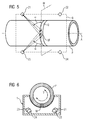
- the four ultrasonic transducers 21 to 24 are located in a curved plane T such that all transducers 21 and 24 are placed equidistant and at right angles to its neighboring transducers around the inspection area M (point-symmetrical in the projection plane B in FIG 4 and 5 ).
- the four ultrasonic transducers 21 to 24 are aligned such that an ultrasonic beam transmitted by one of the transducers 21 to 24 impinge the outer surface of the tube P under such an angle that the ultrasonic beam is guided between the inner and outer surface towards the inspection area M of the butt-welded portion Q.
- a crucial aspect is the calculation for the equidistance of the transducers 21 to 24 in the housing element H in respect to the tube P.
- the alignment depends on the tube diameter, the wall thickness d, the angle of impinging the ultrasonic beams and the number of required total-reflections at the inner and the outer surface of the tube wall. Due to the distortion causes by traversing at an angle through a curved shape, the three-dimensional cross section wherein the ultrasound beams travel will be neither a circle or a flat plane, but an ellipse. The ellipse is defined by the angle at which the cross section is taken, and the diameter of the pipe that is under inspection.
- the best and optimized location of the transducers 21 to 24 is at a 45 degree position in respect to the intersection plane W and where the distances from all transducers to the inspection area M are identical. This distance depends on the combination of tube diameter, wall thickness, angle of refraction of the initial ultrasound sound beam, and the number of skips required, to allow the ultrasonic beams to reach the inspection area M of the butt-welded portion Q.
- FIG 6 shows a cross view of the tube P on a circumference plane with the tailor-made apparatus 1 arranged on the outer surface of the tube P.
- the focal points for this parabola coincide with the position of the transmitting and receiving transducers. Since for all transducers the positions are identical, different transducer pairs, each with their own virtual "parabolic mirror", can be created to look for reflectors which are oriented on the parabola, ensuring that reflectors oriented transverse ( FIG 4 ) and longitudinal ( FIG 5 ) can be found in a single pass around the pipe. For each tube diameter a specific apparatus is needed to ensure that the position and distance of the ultrasonic transducers is guaranteed to be at 45° with a tolerance of ⁇ 2°, while at the same time ensuring that the distance towards the inspection area M is identical, and within a plus / minus one Millimeter tolerance.
- the transducer arrangement fixed in housing H, is moved along the circumference ⁇ of the tube close to the butt-welded portion Q.
- the position and directional movement are recorded by a detecting element D as indicated in FIG 1 .
- a flaw LF or TF (as shown in FIG 8 ) is hit by an ultrasonic beam, transmitted from, for example, transducer 21, the reflection can either hit transducer 22 or 23, depending on the flaw orientation.
- a signal on C21-22 or C23-24 is a transverse flaw TF, on C21-23 or C22-24 a longitudinal flaw LF.
- transducer 22 Each transducer sends in turn and for this example the transducer 22 will also send a signal reflecting back onto transducer 21. These duplicate signals are not recorded for ease of evaluation. Therefore, only the unique pairs C21-22, C22-24, C21-23 and C23-24 as indicated in FIG 7 are shown.
- the apparatus 1 is unique to the tube diameter and can communicate its ID to a sampling device, which, in turn, preloads the parameters required to perform the weld inspection.
- Files could be stored also in a graphic representation of the tube under test e.g. as a tube grid. for easy data allocation and retrieval for later auditing and analysis.
- FIG 7 shows a sample of measurement output. Left two columns show transverse flaw TF, right columns depict the longitudinal flaw LF. For each channel the signal strength of the reflection is shown on the horizontal axes. Circumferential position of the apparatus is shown on the vertical axis. For the results of FIG 7 , a test tube as shown in FIG 8 , is used.
- the longitudinal flaw orientation is not exactly radial, so only one longitudinal channel shows signal response, indicating the ability to determine flaw orientation.
- the circumferential length of the transverse flaw translates to the duration of the transition of the flaw through the ultrasound beams.
- the actual circumferential position of the transverse flaw TF coincides with the maximum combined amplitude 25 in both channels.
Landscapes
- Physics & Mathematics (AREA)
- Health & Medical Sciences (AREA)
- Life Sciences & Earth Sciences (AREA)
- Chemical & Material Sciences (AREA)
- Analytical Chemistry (AREA)
- Biochemistry (AREA)
- General Health & Medical Sciences (AREA)
- General Physics & Mathematics (AREA)
- Immunology (AREA)
- Pathology (AREA)
- Investigating Or Analyzing Materials By The Use Of Ultrasonic Waves (AREA)
Priority Applications (2)
| Application Number | Priority Date | Filing Date | Title |
|---|---|---|---|
| EP16166295.2A EP3236255A1 (de) | 2016-04-21 | 2016-04-21 | Vorrichtung und verfahren zum beobachten eines stossgeschweissten rohrteils |
| PCT/EP2017/058204 WO2017182282A1 (en) | 2016-04-21 | 2017-04-06 | Apparatus and method for observing a butt-welded portion of a tube |
Applications Claiming Priority (1)
| Application Number | Priority Date | Filing Date | Title |
|---|---|---|---|
| EP16166295.2A EP3236255A1 (de) | 2016-04-21 | 2016-04-21 | Vorrichtung und verfahren zum beobachten eines stossgeschweissten rohrteils |
Publications (1)
| Publication Number | Publication Date |
|---|---|
| EP3236255A1 true EP3236255A1 (de) | 2017-10-25 |
Family
ID=55802277
Family Applications (1)
| Application Number | Title | Priority Date | Filing Date |
|---|---|---|---|
| EP16166295.2A Withdrawn EP3236255A1 (de) | 2016-04-21 | 2016-04-21 | Vorrichtung und verfahren zum beobachten eines stossgeschweissten rohrteils |
Country Status (2)
| Country | Link |
|---|---|
| EP (1) | EP3236255A1 (de) |
| WO (1) | WO2017182282A1 (de) |
Cited By (2)
| Publication number | Priority date | Publication date | Assignee | Title |
|---|---|---|---|---|
| CN113138231A (zh) * | 2021-04-13 | 2021-07-20 | 武汉理工大学 | 一种航空发动机机匣环锻件超声相控阵检测装置及方法 |
| EP3701257A4 (de) * | 2017-10-27 | 2021-08-11 | Westinghouse Electric Company Llc | Vorrichtung und verfahren zur verbesserten erkennung von korrosionsverdünnung |
Families Citing this family (1)
| Publication number | Priority date | Publication date | Assignee | Title |
|---|---|---|---|---|
| US11274952B2 (en) * | 2018-11-16 | 2022-03-15 | Levitronix Gmbh | Ultrasonic measuring device for ultrasonic measurement on a flowing fluid |
Citations (4)
| Publication number | Priority date | Publication date | Assignee | Title |
|---|---|---|---|---|
| GB1001857A (en) * | 1962-12-20 | 1965-08-18 | Dickinson Ben Wade O Iii | Method and apparatus for flaw detection by ultrasonic means |
| GB1118521A (en) * | 1965-03-10 | 1968-07-03 | Italsider Spa | Method and apparatus for ultrasonic inspection of welds |
| US4195530A (en) * | 1978-08-14 | 1980-04-01 | Republic Steel Corporation | Ultrasonic inspection |
| JPS62269056A (ja) * | 1986-05-19 | 1987-11-21 | Toshiba Corp | 無軌道式超音波探傷装置 |
-
2016
- 2016-04-21 EP EP16166295.2A patent/EP3236255A1/de not_active Withdrawn
-
2017
- 2017-04-06 WO PCT/EP2017/058204 patent/WO2017182282A1/en not_active Ceased
Patent Citations (4)
| Publication number | Priority date | Publication date | Assignee | Title |
|---|---|---|---|---|
| GB1001857A (en) * | 1962-12-20 | 1965-08-18 | Dickinson Ben Wade O Iii | Method and apparatus for flaw detection by ultrasonic means |
| GB1118521A (en) * | 1965-03-10 | 1968-07-03 | Italsider Spa | Method and apparatus for ultrasonic inspection of welds |
| US4195530A (en) * | 1978-08-14 | 1980-04-01 | Republic Steel Corporation | Ultrasonic inspection |
| JPS62269056A (ja) * | 1986-05-19 | 1987-11-21 | Toshiba Corp | 無軌道式超音波探傷装置 |
Cited By (3)
| Publication number | Priority date | Publication date | Assignee | Title |
|---|---|---|---|---|
| EP3701257A4 (de) * | 2017-10-27 | 2021-08-11 | Westinghouse Electric Company Llc | Vorrichtung und verfahren zur verbesserten erkennung von korrosionsverdünnung |
| US11549916B2 (en) | 2017-10-27 | 2023-01-10 | Westinghouse Electric Company Llc | Apparatus and method for improved corrosion thinning detection |
| CN113138231A (zh) * | 2021-04-13 | 2021-07-20 | 武汉理工大学 | 一种航空发动机机匣环锻件超声相控阵检测装置及方法 |
Also Published As
| Publication number | Publication date |
|---|---|
| WO2017182282A1 (en) | 2017-10-26 |
Similar Documents
| Publication | Publication Date | Title |
|---|---|---|
| CN101103266B (zh) | 用于不锈钢的超声相控阵设备和方法 | |
| US6925145B2 (en) | High speed digital radiographic inspection of piping | |
| CN105911145B (zh) | 一种换热器管板角焊缝超声相控阵检测方法和装置 | |
| KR20000064549A (ko) | 두께가얇은배관내의크랙검출및측정응위한lamb초음파탐침 | |
| CN112362743A (zh) | 核电站一回路不锈钢boss焊缝相控阵超声检测装置及方法 | |
| CA1320759C (en) | Non-destructive dimensional and flaw inspection of thin wall tube weldments | |
| US20040228432A1 (en) | Remote examination of reactor nozzle j-groove welds | |
| US20150212048A1 (en) | Method and system for determination of geometric features in objects | |
| EP3236255A1 (de) | Vorrichtung und verfahren zum beobachten eines stossgeschweissten rohrteils | |
| US10161913B2 (en) | Metal weld inspection device, associated system and method | |
| Xu et al. | Data fusion of multi-view plane wave imaging for nozzle weld inspection | |
| WO2021053939A1 (ja) | 超音波検査方法および超音波検査装置 | |
| MacLeod et al. | Advanced nondestructive evaluation for welded joints | |
| CN115494095A (zh) | 无损检测装置及其检测方法、无损检测设备 | |
| CN110967400A (zh) | 大型储罐底板缺陷的兰姆波层析成像方法 | |
| Troughton et al. | Development of ultrasonic phased array inspection of polyethylene pipe joints | |
| US3186216A (en) | Method and apparatus for generating and receiving ultrasonic helical waves | |
| Moles et al. | Phased arrays for small diameter, thin-walled piping inspections | |
| Pugalendhi et al. | Use of Phased Array Ultrasonic Testing (PAUT) & Time Of Flight Diffraction (TOFD) in Lieu of Radiography Testing on ASME U Stamp Pressure Vessel fabrication Projects | |
| Guo et al. | Research on phased array ultrasonic technique for testing tube to tube-sheet welds of heat exchanger | |
| KR100768390B1 (ko) | 유도초음파를 이용한 열교환기 검사장치 | |
| Liu | Effectiveness of Radiographic Testing and Phased-Array Ultrasonics in Identifying Sub-Surface Flaws in High-Pressure Piping Systems | |
| Guo et al. | Development of ultrasonic phased array systems for applications in tube and pipe inspection | |
| Murugaiyan | Time of flight diffraction (TOFD), an advanced non-destructive testing technique for inspection of welds for heavy walled pressure vessels | |
| Wei et al. | Study on Ultrasonic Phased Array Detection and CIVA Simulation of Placed Fillet Weld |
Legal Events
| Date | Code | Title | Description |
|---|---|---|---|
| PUAI | Public reference made under article 153(3) epc to a published international application that has entered the european phase |
Free format text: ORIGINAL CODE: 0009012 |
|
| STAA | Information on the status of an ep patent application or granted ep patent |
Free format text: STATUS: THE APPLICATION HAS BEEN PUBLISHED |
|
| AK | Designated contracting states |
Kind code of ref document: A1 Designated state(s): AL AT BE BG CH CY CZ DE DK EE ES FI FR GB GR HR HU IE IS IT LI LT LU LV MC MK MT NL NO PL PT RO RS SE SI SK SM TR |
|
| AX | Request for extension of the european patent |
Extension state: BA ME |
|
| STAA | Information on the status of an ep patent application or granted ep patent |
Free format text: STATUS: THE APPLICATION IS DEEMED TO BE WITHDRAWN |
|
| 18D | Application deemed to be withdrawn |
Effective date: 20180426 |