EP3236285A1 - Capteur optoélectronique - Google Patents
Capteur optoélectronique Download PDFInfo
- Publication number
- EP3236285A1 EP3236285A1 EP17162805.0A EP17162805A EP3236285A1 EP 3236285 A1 EP3236285 A1 EP 3236285A1 EP 17162805 A EP17162805 A EP 17162805A EP 3236285 A1 EP3236285 A1 EP 3236285A1
- Authority
- EP
- European Patent Office
- Prior art keywords
- mirror
- optoelectronic sensor
- sensor according
- mirror element
- light
- Prior art date
- Legal status (The legal status is an assumption and is not a legal conclusion. Google has not performed a legal analysis and makes no representation as to the accuracy of the status listed.)
- Granted
Links
Images

Classifications
-
- G—PHYSICS
- G02—OPTICS
- G02B—OPTICAL ELEMENTS, SYSTEMS OR APPARATUS
- G02B5/00—Optical elements other than lenses
- G02B5/08—Mirrors
- G02B5/0808—Mirrors having a single reflecting layer
-
- B—PERFORMING OPERATIONS; TRANSPORTING
- B29—WORKING OF PLASTICS; WORKING OF SUBSTANCES IN A PLASTIC STATE IN GENERAL
- B29D—PRODUCING PARTICULAR ARTICLES FROM PLASTICS OR FROM SUBSTANCES IN A PLASTIC STATE
- B29D11/00—Producing optical elements, e.g. lenses or prisms
- B29D11/00009—Production of simple or compound lenses
- B29D11/0048—Moulds for lenses
- B29D11/00576—Moulds for lenses with means to engage flash, e.g. HEMA ring
- B29D11/00586—Moulds for lenses with means to engage flash, e.g. HEMA ring and removing the flash or HEMA ring
-
- G—PHYSICS
- G01—MEASURING; TESTING
- G01S—RADIO DIRECTION-FINDING; RADIO NAVIGATION; DETERMINING DISTANCE OR VELOCITY BY USE OF RADIO WAVES; LOCATING OR PRESENCE-DETECTING BY USE OF THE REFLECTION OR RERADIATION OF RADIO WAVES; ANALOGOUS ARRANGEMENTS USING OTHER WAVES
- G01S17/00—Systems using the reflection or reradiation of electromagnetic waves other than radio waves, e.g. lidar systems
- G01S17/02—Systems using the reflection of electromagnetic waves other than radio waves
- G01S17/04—Systems determining the presence of a target
-
- G—PHYSICS
- G01—MEASURING; TESTING
- G01S—RADIO DIRECTION-FINDING; RADIO NAVIGATION; DETERMINING DISTANCE OR VELOCITY BY USE OF RADIO WAVES; LOCATING OR PRESENCE-DETECTING BY USE OF THE REFLECTION OR RERADIATION OF RADIO WAVES; ANALOGOUS ARRANGEMENTS USING OTHER WAVES
- G01S17/00—Systems using the reflection or reradiation of electromagnetic waves other than radio waves, e.g. lidar systems
- G01S17/02—Systems using the reflection of electromagnetic waves other than radio waves
- G01S17/06—Systems determining position data of a target
- G01S17/08—Systems determining position data of a target for measuring distance only
-
- G—PHYSICS
- G01—MEASURING; TESTING
- G01S—RADIO DIRECTION-FINDING; RADIO NAVIGATION; DETERMINING DISTANCE OR VELOCITY BY USE OF RADIO WAVES; LOCATING OR PRESENCE-DETECTING BY USE OF THE REFLECTION OR RERADIATION OF RADIO WAVES; ANALOGOUS ARRANGEMENTS USING OTHER WAVES
- G01S17/00—Systems using the reflection or reradiation of electromagnetic waves other than radio waves, e.g. lidar systems
- G01S17/02—Systems using the reflection of electromagnetic waves other than radio waves
- G01S17/06—Systems determining position data of a target
- G01S17/46—Indirect determination of position data
- G01S17/48—Active triangulation systems, i.e. using the transmission and reflection of electromagnetic waves other than radio waves
-
- G—PHYSICS
- G01—MEASURING; TESTING
- G01S—RADIO DIRECTION-FINDING; RADIO NAVIGATION; DETERMINING DISTANCE OR VELOCITY BY USE OF RADIO WAVES; LOCATING OR PRESENCE-DETECTING BY USE OF THE REFLECTION OR RERADIATION OF RADIO WAVES; ANALOGOUS ARRANGEMENTS USING OTHER WAVES
- G01S7/00—Details of systems according to groups G01S13/00, G01S15/00, G01S17/00
- G01S7/48—Details of systems according to groups G01S13/00, G01S15/00, G01S17/00 of systems according to group G01S17/00
- G01S7/481—Constructional features, e.g. arrangements of optical elements
- G01S7/4811—Constructional features, e.g. arrangements of optical elements common to transmitter and receiver
- G01S7/4812—Constructional features, e.g. arrangements of optical elements common to transmitter and receiver transmitted and received beams following a coaxial path
-
- G—PHYSICS
- G01—MEASURING; TESTING
- G01V—GEOPHYSICS; GRAVITATIONAL MEASUREMENTS; DETECTING MASSES OR OBJECTS; TAGS
- G01V8/00—Prospecting or detecting by optical means
- G01V8/10—Detecting, e.g. by using light barriers
- G01V8/12—Detecting, e.g. by using light barriers using one transmitter and one receiver
- G01V8/14—Detecting, e.g. by using light barriers using one transmitter and one receiver using reflectors
-
- G—PHYSICS
- G01—MEASURING; TESTING
- G01S—RADIO DIRECTION-FINDING; RADIO NAVIGATION; DETERMINING DISTANCE OR VELOCITY BY USE OF RADIO WAVES; LOCATING OR PRESENCE-DETECTING BY USE OF THE REFLECTION OR RERADIATION OF RADIO WAVES; ANALOGOUS ARRANGEMENTS USING OTHER WAVES
- G01S7/00—Details of systems according to groups G01S13/00, G01S15/00, G01S17/00
- G01S7/48—Details of systems according to groups G01S13/00, G01S15/00, G01S17/00 of systems according to group G01S17/00
- G01S7/481—Constructional features, e.g. arrangements of optical elements
- G01S7/4811—Constructional features, e.g. arrangements of optical elements common to transmitter and receiver
- G01S7/4813—Housing arrangements
Definitions
- the present invention relates to an optoelectronic sensor according to the preamble of claim 1.
- optical carriers made of polymer materials are used.
- optical carriers made of polymer materials
- the problem here are the tolerances and precision of the optics carrier.
- Another problem is a strength of the optical carrier, a temperature dependence, and complex processes to produce reflective surfaces on the plastic part.
- conductive shrouds are often required to ensure electromagnetic compatibility (EMC).
- An object of the invention is to provide a mirror element for an optoelectronic sensor, which is inexpensive and has a high surface quality.
- the mirror element should have low tolerances and have a low coefficient of thermal expansion.
- an optoelectronic sensor for detecting objects within a surveillance area, comprising a transmitter unit having a transmitting element for emitting transmitted light beams into the surveillance area, and / or a receiver unit having a receiving element for receiving receiving light beams of the object, wherein the Receiver unit and / or the transmitter unit has at least one mirror element for deflecting the light rays, wherein the mirror element is formed of amorphous metal.
- Amorphous metals or amorphous metal materials which are also referred to as metallic glasses, have due to their non-crystalline structure compared to steel on an electrical conductivity, which is less than in steel.
- the strength and hardness of amorphous metals are increased compared to crystalline metals. This increased strength makes it possible to form thinner surfaces with the same strength. As a result, the mirror element can be formed thin-walled.
- Another advantage of the invention is that amorphous metals have comparatively low shrinkage rates and can therefore be produced tool-bound by means of injection-molding-like processes. This allows a particularly fast and cost-effective production of the mirror element and thus of the optoelectronic sensor.
- the mirror element is made entirely by an injection molding process. Accordingly, the mirror element is designed as an injection-molded component. This allows a particularly simple and inexpensive production. In the case of crystalline metals, production by means of injection molding would be disadvantageous due to the high shrinkage rates.
- the mirror element has low tolerance values, whereby the mirror element can be manufactured with high precision.
- the surface quality of the mirror element can be made very high.
- a high surface quality of the mirror surface or of the mirror can already be produced or provided by the injection-molded component without subsequent processing since the surface quality of the molded part itself already has a high surface quality.
- the mirror element is also inexpensive to produce.
- the amorphous metal has a low temperature expansion coefficient.
- the optical properties of the mirror element change only slightly with temperature changes.
- an optoelectronic sensor is formed with constant optical properties in the event of a temperature change.
- the optoelectronic sensor is preferably a light barrier, a reflection light barrier or a light sensor.
- a light barrier can be designed as a through-beam sensor.
- the light transmitter and the light receiver are arranged opposite one another and an interruption of the light beam leads in the evaluation unit of the light receiver to an object detection signal.
- the light transmitter or transmitter unit and the light receiver or receiver unit are accommodated on the same side of a monitoring area, usually in a single housing.
- a retroreflector is arranged, which reflects the light emitted by the light emitter back through 180 ° in the light receiver.
- the light transmitter or transmitter unit and the light receiver or receiver unit are arranged in a common housing.
- the light rays emitted by the light emitter are reflected or remitted on an object.
- the received light can be evaluated energetically. If a certain threshold is exceeded, an object detection signal is output.
- the light sensor can also be designed as Triangulationstaster.
- a Triangulationstaster the receiving element is spatially resolved and arranged the light emitter spaced from the receiving element.
- a light spot emitted by the light emitter is returned by an object, imaged via the reception lens onto the spatially resolving reception element.
- the light spot is imaged at different positions, it being possible to infer the distance of the object from the position of the light spot on the receiving element.
- a sensor can also be a sensor according to the light transit time method.
- a short light pulse or a group of light pulses is emitted by the light transmitter.
- the one or more light pulses are reflected or remitted by an object and received by the receiving element of the light receiver. From a downstream evaluation unit, the duration of the light from sending to receiving evaluated and calculated from the distance of the object.
- the amorphous metal is an amorphous metal alloy.
- Such amorphous metal alloys are available in a variety of designs and are relatively inexpensive compared to alternative crystalline metals such as titanium.
- the type of alloy can be tailored to the particular application.
- a defined electrical potential is connected to the mirror element.
- the defined electrical potential of the sensor is an electrical potential which is connected to the electronic card of the sensor.
- the electrical potential is connected, for example, from the electronic board via a conductive or metallic contact or a metallic pin to the mirror element. By the conductive contact, an electrical connection between the mirror element and the electronic board is produced when mounting the mirror element. As a result, the electromagnetic compatibility of the optoelectronic sensor is improved.
- the mirror of the mirror element is concavely curved.
- the mirror is thus curved inwards, whereby a concave mirror is formed.
- light rays falling on the mirror can be focused or focused through the mirror.
- an additional optical component such. As a lens can be saved.
- the mirror of the mirror element is planar.
- a plane or flat mirror reflects the light at each point identically with parallel incident light rays.
- a plane mirror can also have a focusing effect if the incident light beams are already converging.
- the mirror element is arranged in a mirror carrier, wherein the mirror element and the mirror carrier are integrally formed and made of amorphous metal.
- the mirror support forms, for example, a frame for the mirror element, as a result of which the mirror element is made mechanically more stable. This ensures a particularly simple, robust and stable design.
- the mirror carrier has, for example, additional side walls.
- the mirror support serves as a mounting base for other sensor components.
- the mirror carrier has, for example, fastening receptacles for a sensor housing.
- the mirror support may have reference surfaces for positioning other sensor components.
- the mirror support may have reference surfaces in order to position the mirror support itself and thus the mirror element itself relative to another reference surface in order to ensure an exact alignment of the mirror element.
- the mirror support has a complex structure.
- This complex structure can be used for attachment and can be adapted to the shape of other adjacent components, so that the most compact possible sensor is formed.
- At least two mirror elements and the mirror carrier are integrally formed.
- received light beams can be deflected twice by the successively arranged mirror elements in order to supply them, for example, to a receiving element.
- the respective mirror elements can also be designed differently.
- a first mirror element may be concave and a second mirror element may be flat.
- a plurality of mirror elements are provided for a plurality of transmitting units or for a plurality of receiving units.
- At least one mirror element has an opening for the transmitted light beams.
- the transmitter unit can be integrated with the transmitter element in the mirror element for the receiver unit, resulting in a compact sensor.
- the transmitted light beams and the received light beams may be collimated.
- the opening is preferably a round opening or a hole, which is arranged, for example, near the middle or in the center in the mirror element.
- the mirror element or the mirror support is mechanically connected to a printed circuit board.
- a printed circuit board This allows the sensor to be very simple. For example, all electronic components are arranged on the circuit board and arranged on the mirror support all optical components. As a result, the sensor is almost completely built up by the mechanical connection of the mirror carrier with the printed circuit board. Only an optional electrical connection and the sensor housing need to be supplemented to obtain an operational optoelectronic sensor.
- the transmitting element and / or the receiving element and an evaluation unit is arranged on the printed circuit board.
- the printed circuit board optionally has at least one reference surface which is connected to at least one optional reference surface of the mirror carrier. By the transmitting element and / or the receiving element is aligned and referenced to the mirror element.
- the mirror support has at least one receptacle for at least one optical element.
- the optical element can, for example, be at least one refractive element, for example at least one lens, for example a lens, for example at least one diffractive element or, for example, at least one light-guiding element, for example at least one light guide.
- the mirror carrier in turn has reference surfaces for the optical element.
- the optical element is a converging lens.
- the mirror carrier in addition to the mirror element, has at least one surface which is formed integrally with the mirror carrier in order to form an EMC shielding surface.
- a plurality of surfaces may be provided which surround the electronics of the circuit board, so that the electronics of the circuit board is shielded, whereby the sensor has a better electromagnetic compatibility.
- the sensor is better protected against interfering foreign electromagnetic waves.
- the mirror element is automatically equipped on a printed circuit board.
- an entire sensor unit consisting of at least one populated printed circuit board and the mirror element can be produced automatically.
- the sensor is very inexpensive to produce.
- FIG. 1 shows an optoelectronic sensor 1 with a housing 21, a windscreen 22 and an electrical connection 23rd
- the optoelectronic sensor 1 is preferably a light barrier, a reflection light barrier, a light sensor, or a distance sensor.
- a reflection light barrier the light transmitter or transmitter unit and the light receiver or receiver unit are accommodated on the same side of a monitoring area, usually in a single housing.
- a retroreflector is arranged, which reflects the light emitted by the light emitter back through 180 ° in the light receiver.
- the light transmitter or transmitter unit and the light receiver or receiver unit are arranged in a common housing.
- the light rays emitted by the light emitter are reflected or remitted on an object.
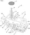
- FIG. 2 shows the internal structure of the optoelectronic sensor 1 without housing.
- FIG. 2 shows an optoelectronic sensor 1 for detecting objects 2 within a monitoring area 3, with a transmitter unit 4 with a transmitting element 5 for emitting transmitted light beams 6 in the surveillance area 3, and a receiver unit 7 with a receiving element 8 for receiving received light beams 9 of the object 2, wherein the receiver unit 7 has at least one mirror element 10 for deflecting the received light beams 9, wherein the mirror element 10 is formed from amorphous metal 11.
- the mirror element 10 is completely made by an injection molding process.
- a high surface quality of the mirror surface or of the mirror 12 can already be produced or provided by the injection-molded component without subsequent processing.
- the amorphous metal 11 is an amorphous metal alloy.
- a defined electrical potential is connected to the mirror element 10.
- the defined electrical potential of the optoelectronic sensor 1 is an electrical potential which is connected to the printed circuit board 15 or electronic card of the optoelectronic sensor 1.
- the electrical potential is connected, for example, from the printed circuit board 15 via a conductive or metallic contact or a metallic pin to the mirror element.
- the mirror 12 of the mirror element 10 is concavely curved.
- the mirror 12 is thus curved inwards, whereby a concave mirror is formed.
- receiving light beams 9 falling on the mirror 12 can be focused or focused by the mirror 12.
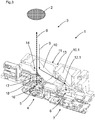
- FIG. 3 which is a sectional view according to FIG. 2 represents, is a second mirror 12.1 of the mirror element 10.1 formed plan.
- the mirror elements 10, 10.1 are arranged in a mirror support 13, wherein the mirror elements 10, 10.1 and the mirror support 13 are integrally formed and consist of amorphous metal 11.
- the mirror support 13 forms, for example, a frame for the mirror elements 10, 10.1, whereby the mirror elements 10, 10.1 are made mechanically more stable. This ensures a particularly simple, robust and stable design.
- the mirror carrier 13 has, for example, additional side walls 24.
- the mirror support 13 serves as a mounting base for other sensor components.
- a connection unit 25 can be attached to the mirror support 13.
- the mirror support 13 has, for example, fastening receptacles for a sensor housing.
- the mirror support 13 may have reference surfaces for positioning other sensor components.
- the mirror support 13 can have reference surfaces in order to precisely position the mirror support 13 and thus the mirror elements 10, 10.1 themselves relative to another reference surface in order to ensure exact alignment of the mirror elements 10, 10.1.
- the mirror carrier 13 has a complex structure or complex surface.
- This complex structure or complex surface can be used for attachment serve and can be adapted to the shape of other adjacent components, so that a compact optoelectronic sensor 1 is formed as possible.
- At least two mirror elements 10, 10.1 and the mirror support 13 are integrally formed.
- received light beams can be deflected twice by the successively arranged mirror elements 10, 10.1 in order, for example, to supply them to a receiving element.
- the respective mirror elements 10, 10.1 are formed differently.
- a first mirror element 10 is concave and a second mirror element 10.1 is planar.
- the mirror element 10 has an opening 14 for the transmitted light beams 6.
- the transmitter unit 4 with the transmitter element 5 can be integrated in the mirror element 10 for the receiver unit 7.
- the transmitted light beams 6 and the received light beams 9 can be collimated.
- the opening 14 is preferably a round opening 14 or a hole which is arranged, for example, near the middle or in the middle in the mirror element 10.
- the mirror element 10 or the mirror support 13 is mechanically connected to a printed circuit board 15.
- all electronic components are arranged on the printed circuit board 15 and all optical components are arranged on the mirror carrier 13.
- the optoelectronic sensor 1 is almost completely built up by the mechanical connection of the mirror carrier 13 with the circuit board 15. Only an optional electrical connection and the sensor housing must be supplemented to obtain an operational optoelectronic sensor 1.
- the transmitting element 5 and / or the receiving element 8 and an evaluation unit is arranged on the printed circuit board 15.
- the printed circuit board optionally has at least one reference surface, which is connected to at least one optional reference surface of the mirror carrier 13. As a result, the transmitting element 5 and the receiving element 8 are aligned and referenced to the mirror element 10.
- the mirror carrier 13 has at least one receptacle 16 for at least one optical element 17.
- the optical element 17 can be, for example, at least one refractive element, for example at least one converging lens 18.
- the mirror carrier 13 in turn has reference surfaces for the optical element 17.
- the mirror support 13 in addition to the mirror elements 10, 10.1 at least one surface 19 which is integrally formed to the mirror support 13 to form an EMC shielding surface 20.
- a plurality of surfaces 19 may be provided which shield the electronics of the circuit board 15, so that the electronics of the circuit board 15 is shielded, whereby the optoelectronic sensor 1 has a better electromagnetic compatibility.
- FIG. 2 is the mirror support 13 and the mirror elements 10, 10.1 automatically equipped on a printed circuit board 15.
Landscapes
- Physics & Mathematics (AREA)
- Engineering & Computer Science (AREA)
- Electromagnetism (AREA)
- General Physics & Mathematics (AREA)
- Computer Networks & Wireless Communication (AREA)
- Radar, Positioning & Navigation (AREA)
- Remote Sensing (AREA)
- Health & Medical Sciences (AREA)
- Optics & Photonics (AREA)
- Manufacturing & Machinery (AREA)
- Ophthalmology & Optometry (AREA)
- Mechanical Engineering (AREA)
- Life Sciences & Earth Sciences (AREA)
- General Life Sciences & Earth Sciences (AREA)
- Geophysics (AREA)
- Light Receiving Elements (AREA)
- Geophysics And Detection Of Objects (AREA)
Applications Claiming Priority (1)
| Application Number | Priority Date | Filing Date | Title |
|---|---|---|---|
| DE102016107153.6A DE102016107153B4 (de) | 2016-04-18 | 2016-04-18 | Optoelektronischer Sensor |
Publications (2)
| Publication Number | Publication Date |
|---|---|
| EP3236285A1 true EP3236285A1 (fr) | 2017-10-25 |
| EP3236285B1 EP3236285B1 (fr) | 2018-12-19 |
Family
ID=58412995
Family Applications (1)
| Application Number | Title | Priority Date | Filing Date |
|---|---|---|---|
| EP17162805.0A Active EP3236285B1 (fr) | 2016-04-18 | 2017-03-24 | Capteur optoélectronique |
Country Status (2)
| Country | Link |
|---|---|
| EP (1) | EP3236285B1 (fr) |
| DE (1) | DE102016107153B4 (fr) |
Families Citing this family (1)
| Publication number | Priority date | Publication date | Assignee | Title |
|---|---|---|---|---|
| DE102024131467A1 (de) * | 2024-10-29 | 2026-04-30 | Sick Ag | Optoelektronischer sensor zum erfassen von objekten |
Citations (8)
| Publication number | Priority date | Publication date | Assignee | Title |
|---|---|---|---|---|
| WO2006060081A2 (fr) * | 2004-10-19 | 2006-06-08 | Liquidmetal Technologies, Inc. | Miroirs metalliques formes a partir d'alliages amorphes |
| JP2006265050A (ja) * | 2005-03-24 | 2006-10-05 | Canon Inc | 光学素子成形型 |
| DE102005013317A1 (de) * | 2005-03-22 | 2006-10-05 | Leuze Electronic Gmbh & Co Kg | Optischer Sensor |
| US20100105980A1 (en) * | 2007-01-31 | 2010-04-29 | Namiki Seimitsu Houseki Kabushiki Kaisha | Motor and endoscope probe equipped with motor |
| DE202009007612U1 (de) * | 2009-05-28 | 2010-10-14 | Sick Ag | Reflexionslichtschrankensensor |
| JP2012113146A (ja) * | 2010-11-25 | 2012-06-14 | Canon Electronics Inc | 振動素子、光走査装置、アクチュエータ装置、映像投影装置及び画像形成装置 |
| DE202011052365U1 (de) * | 2011-12-20 | 2013-03-21 | Sick Ag | Reflexionslichtschranke |
| US20130139964A1 (en) * | 2011-11-16 | 2013-06-06 | California Institute Of Technology | Amorphous metals and composites as mirrors and mirror assemblies |
Family Cites Families (6)
| Publication number | Priority date | Publication date | Assignee | Title |
|---|---|---|---|---|
| DE952155C (de) * | 1954-05-23 | 1956-11-08 | Erwin Sick | Lichtelektrische Schranke |
| JP5203259B2 (ja) * | 2009-03-09 | 2013-06-05 | オリンパス株式会社 | 光学部品の製造方法 |
| DE102009051188A1 (de) * | 2009-10-29 | 2011-05-19 | Siemens Aktiengesellschaft | Lichtsignalgeber und Lichtempfänger für einen optischen Sensor |
| LU91714B1 (en) * | 2010-07-29 | 2012-01-30 | Iee Sarl | Active illumination scanning imager |
| JP6018926B2 (ja) * | 2013-01-09 | 2016-11-02 | 富士フイルム株式会社 | マイクロミラーデバイス及びその製造方法 |
| WO2015040807A1 (fr) * | 2013-09-18 | 2015-03-26 | Canon Kabushiki Kaisha | Unité optique, élément optique et procédé de fabrication associé |
-
2016
- 2016-04-18 DE DE102016107153.6A patent/DE102016107153B4/de not_active Expired - Fee Related
-
2017
- 2017-03-24 EP EP17162805.0A patent/EP3236285B1/fr active Active
Patent Citations (8)
| Publication number | Priority date | Publication date | Assignee | Title |
|---|---|---|---|---|
| WO2006060081A2 (fr) * | 2004-10-19 | 2006-06-08 | Liquidmetal Technologies, Inc. | Miroirs metalliques formes a partir d'alliages amorphes |
| DE102005013317A1 (de) * | 2005-03-22 | 2006-10-05 | Leuze Electronic Gmbh & Co Kg | Optischer Sensor |
| JP2006265050A (ja) * | 2005-03-24 | 2006-10-05 | Canon Inc | 光学素子成形型 |
| US20100105980A1 (en) * | 2007-01-31 | 2010-04-29 | Namiki Seimitsu Houseki Kabushiki Kaisha | Motor and endoscope probe equipped with motor |
| DE202009007612U1 (de) * | 2009-05-28 | 2010-10-14 | Sick Ag | Reflexionslichtschrankensensor |
| JP2012113146A (ja) * | 2010-11-25 | 2012-06-14 | Canon Electronics Inc | 振動素子、光走査装置、アクチュエータ装置、映像投影装置及び画像形成装置 |
| US20130139964A1 (en) * | 2011-11-16 | 2013-06-06 | California Institute Of Technology | Amorphous metals and composites as mirrors and mirror assemblies |
| DE202011052365U1 (de) * | 2011-12-20 | 2013-03-21 | Sick Ag | Reflexionslichtschranke |
Also Published As
| Publication number | Publication date |
|---|---|
| DE102016107153A1 (de) | 2017-10-19 |
| EP3236285B1 (fr) | 2018-12-19 |
| DE102016107153B4 (de) | 2018-10-18 |
Similar Documents
| Publication | Publication Date | Title |
|---|---|---|
| EP1058142A2 (fr) | Système de balayage laser comprenant une lentille boule | |
| DE102011113172A1 (de) | Optoelektronisches Bauelement | |
| EP1929329B1 (fr) | Dispositif de mesure electro-optique | |
| EP3388857B1 (fr) | Dispositif de balayage laser et procédé de vérification de la capacité de fonctionnement | |
| DE10331074A1 (de) | Sensoranordnung zur Abstands- und/oder Geschwindigkeitsmessung | |
| EP1845334A1 (fr) | Capteur optique | |
| EP3236285B1 (fr) | Capteur optoélectronique | |
| DE10308085B4 (de) | Optoelektronische Vorrichtung | |
| DE10201746A1 (de) | Optoelektronische Vorrichtung | |
| EP1102086B1 (fr) | Dispositif opto-électronique | |
| DE202016102035U1 (de) | Optoelektronischer Sensor | |
| EP1624322A1 (fr) | Capteur optique | |
| EP3907547A1 (fr) | Capteur optoélectronique | |
| DE202019106231U1 (de) | Rotationsfähiger optischer Kurzstrecken-Transceiver | |
| DE29620422U1 (de) | Optoelektronischer Sensor mit in einem Gehäusegrundkörper integrierten Haltevorrichtungen | |
| DE102016121913A1 (de) | Mehrstrahllichtschranke | |
| DE2946111A1 (de) | Optischer koerper fuer ein lidar-system | |
| EP1760509A2 (fr) | Procédé destiné à l'alignement d'un élément illustré et appareil de mesure aligné selon un tel procédé | |
| DE102008056071B4 (de) | Optischer Sensor zur Objektdetektion | |
| DE19844238C2 (de) | Optoelektronische Vorrichtung | |
| DE202020102514U1 (de) | Optoelektronischer Sensor | |
| EP3312760B1 (fr) | Capteur optique | |
| EP1341118B1 (fr) | Appareil opto-électronique | |
| EP4369031B1 (fr) | Capteur optoélectronique | |
| DE202016106394U1 (de) | Mehrstrahllichtschranke |
Legal Events
| Date | Code | Title | Description |
|---|---|---|---|
| PUAI | Public reference made under article 153(3) epc to a published international application that has entered the european phase |
Free format text: ORIGINAL CODE: 0009012 |
|
| STAA | Information on the status of an ep patent application or granted ep patent |
Free format text: STATUS: THE APPLICATION HAS BEEN PUBLISHED |
|
| AK | Designated contracting states |
Kind code of ref document: A1 Designated state(s): AL AT BE BG CH CY CZ DE DK EE ES FI FR GB GR HR HU IE IS IT LI LT LU LV MC MK MT NL NO PL PT RO RS SE SI SK SM TR |
|
| AX | Request for extension of the european patent |
Extension state: BA ME |
|
| STAA | Information on the status of an ep patent application or granted ep patent |
Free format text: STATUS: REQUEST FOR EXAMINATION WAS MADE |
|
| 17P | Request for examination filed |
Effective date: 20180216 |
|
| RBV | Designated contracting states (corrected) |
Designated state(s): AL AT BE BG CH CY CZ DE DK EE ES FI FR GB GR HR HU IE IS IT LI LT LU LV MC MK MT NL NO PL PT RO RS SE SI SK SM TR |
|
| REG | Reference to a national code |
Ref country code: DE Ref legal event code: R079 Ref document number: 502017000523 Country of ref document: DE Free format text: PREVIOUS MAIN CLASS: G01S0017020000 Ipc: G02B0005080000 |
|
| RIC1 | Information provided on ipc code assigned before grant |
Ipc: G01V 8/14 20060101ALI20180417BHEP Ipc: G02B 5/08 20060101AFI20180417BHEP Ipc: G01S 17/48 20060101ALI20180417BHEP Ipc: B29D 11/00 20060101ALI20180417BHEP Ipc: G01S 17/02 20060101ALI20180417BHEP Ipc: G01S 17/08 20060101ALI20180417BHEP Ipc: G01S 7/481 20060101ALI20180417BHEP |
|
| GRAP | Despatch of communication of intention to grant a patent |
Free format text: ORIGINAL CODE: EPIDOSNIGR1 |
|
| STAA | Information on the status of an ep patent application or granted ep patent |
Free format text: STATUS: GRANT OF PATENT IS INTENDED |
|
| INTG | Intention to grant announced |
Effective date: 20180528 |
|
| GRAJ | Information related to disapproval of communication of intention to grant by the applicant or resumption of examination proceedings by the epo deleted |
Free format text: ORIGINAL CODE: EPIDOSDIGR1 |
|
| STAA | Information on the status of an ep patent application or granted ep patent |
Free format text: STATUS: REQUEST FOR EXAMINATION WAS MADE |
|
| GRAP | Despatch of communication of intention to grant a patent |
Free format text: ORIGINAL CODE: EPIDOSNIGR1 |
|
| STAA | Information on the status of an ep patent application or granted ep patent |
Free format text: STATUS: GRANT OF PATENT IS INTENDED |
|
| INTC | Intention to grant announced (deleted) | ||
| GRAJ | Information related to disapproval of communication of intention to grant by the applicant or resumption of examination proceedings by the epo deleted |
Free format text: ORIGINAL CODE: EPIDOSDIGR1 |
|
| STAA | Information on the status of an ep patent application or granted ep patent |
Free format text: STATUS: REQUEST FOR EXAMINATION WAS MADE |
|
| INTG | Intention to grant announced |
Effective date: 20180925 |
|
| GRAP | Despatch of communication of intention to grant a patent |
Free format text: ORIGINAL CODE: EPIDOSNIGR1 |
|
| STAA | Information on the status of an ep patent application or granted ep patent |
Free format text: STATUS: GRANT OF PATENT IS INTENDED |
|
| GRAS | Grant fee paid |
Free format text: ORIGINAL CODE: EPIDOSNIGR3 |
|
| INTC | Intention to grant announced (deleted) | ||
| GRAA | (expected) grant |
Free format text: ORIGINAL CODE: 0009210 |
|
| STAA | Information on the status of an ep patent application or granted ep patent |
Free format text: STATUS: THE PATENT HAS BEEN GRANTED |
|
| INTG | Intention to grant announced |
Effective date: 20181031 |
|
| AK | Designated contracting states |
Kind code of ref document: B1 Designated state(s): AL AT BE BG CH CY CZ DE DK EE ES FI FR GB GR HR HU IE IS IT LI LT LU LV MC MK MT NL NO PL PT RO RS SE SI SK SM TR |
|
| REG | Reference to a national code |
Ref country code: GB Ref legal event code: FG4D Free format text: NOT ENGLISH |
|
| REG | Reference to a national code |
Ref country code: CH Ref legal event code: EP |
|
| REG | Reference to a national code |
Ref country code: IE Ref legal event code: FG4D Free format text: LANGUAGE OF EP DOCUMENT: GERMAN |
|
| REG | Reference to a national code |
Ref country code: DE Ref legal event code: R096 Ref document number: 502017000523 Country of ref document: DE |
|
| REG | Reference to a national code |
Ref country code: AT Ref legal event code: REF Ref document number: 1079311 Country of ref document: AT Kind code of ref document: T Effective date: 20190115 |
|
| REG | Reference to a national code |
Ref country code: NL Ref legal event code: MP Effective date: 20181219 |
|
| PG25 | Lapsed in a contracting state [announced via postgrant information from national office to epo] |
Ref country code: LV Free format text: LAPSE BECAUSE OF FAILURE TO SUBMIT A TRANSLATION OF THE DESCRIPTION OR TO PAY THE FEE WITHIN THE PRESCRIBED TIME-LIMIT Effective date: 20181219 Ref country code: HR Free format text: LAPSE BECAUSE OF FAILURE TO SUBMIT A TRANSLATION OF THE DESCRIPTION OR TO PAY THE FEE WITHIN THE PRESCRIBED TIME-LIMIT Effective date: 20181219 Ref country code: BG Free format text: LAPSE BECAUSE OF FAILURE TO SUBMIT A TRANSLATION OF THE DESCRIPTION OR TO PAY THE FEE WITHIN THE PRESCRIBED TIME-LIMIT Effective date: 20190319 Ref country code: NO Free format text: LAPSE BECAUSE OF FAILURE TO SUBMIT A TRANSLATION OF THE DESCRIPTION OR TO PAY THE FEE WITHIN THE PRESCRIBED TIME-LIMIT Effective date: 20190319 Ref country code: FI Free format text: LAPSE BECAUSE OF FAILURE TO SUBMIT A TRANSLATION OF THE DESCRIPTION OR TO PAY THE FEE WITHIN THE PRESCRIBED TIME-LIMIT Effective date: 20181219 Ref country code: LT Free format text: LAPSE BECAUSE OF FAILURE TO SUBMIT A TRANSLATION OF THE DESCRIPTION OR TO PAY THE FEE WITHIN THE PRESCRIBED TIME-LIMIT Effective date: 20181219 |
|
| REG | Reference to a national code |
Ref country code: LT Ref legal event code: MG4D |
|
| PG25 | Lapsed in a contracting state [announced via postgrant information from national office to epo] |
Ref country code: SE Free format text: LAPSE BECAUSE OF FAILURE TO SUBMIT A TRANSLATION OF THE DESCRIPTION OR TO PAY THE FEE WITHIN THE PRESCRIBED TIME-LIMIT Effective date: 20181219 Ref country code: RS Free format text: LAPSE BECAUSE OF FAILURE TO SUBMIT A TRANSLATION OF THE DESCRIPTION OR TO PAY THE FEE WITHIN THE PRESCRIBED TIME-LIMIT Effective date: 20181219 Ref country code: AL Free format text: LAPSE BECAUSE OF FAILURE TO SUBMIT A TRANSLATION OF THE DESCRIPTION OR TO PAY THE FEE WITHIN THE PRESCRIBED TIME-LIMIT Effective date: 20181219 Ref country code: GR Free format text: LAPSE BECAUSE OF FAILURE TO SUBMIT A TRANSLATION OF THE DESCRIPTION OR TO PAY THE FEE WITHIN THE PRESCRIBED TIME-LIMIT Effective date: 20190320 |
|
| PG25 | Lapsed in a contracting state [announced via postgrant information from national office to epo] |
Ref country code: NL Free format text: LAPSE BECAUSE OF FAILURE TO SUBMIT A TRANSLATION OF THE DESCRIPTION OR TO PAY THE FEE WITHIN THE PRESCRIBED TIME-LIMIT Effective date: 20181219 |
|
| PG25 | Lapsed in a contracting state [announced via postgrant information from national office to epo] |
Ref country code: PT Free format text: LAPSE BECAUSE OF FAILURE TO SUBMIT A TRANSLATION OF THE DESCRIPTION OR TO PAY THE FEE WITHIN THE PRESCRIBED TIME-LIMIT Effective date: 20190419 Ref country code: ES Free format text: LAPSE BECAUSE OF FAILURE TO SUBMIT A TRANSLATION OF THE DESCRIPTION OR TO PAY THE FEE WITHIN THE PRESCRIBED TIME-LIMIT Effective date: 20181219 Ref country code: CZ Free format text: LAPSE BECAUSE OF FAILURE TO SUBMIT A TRANSLATION OF THE DESCRIPTION OR TO PAY THE FEE WITHIN THE PRESCRIBED TIME-LIMIT Effective date: 20181219 Ref country code: PL Free format text: LAPSE BECAUSE OF FAILURE TO SUBMIT A TRANSLATION OF THE DESCRIPTION OR TO PAY THE FEE WITHIN THE PRESCRIBED TIME-LIMIT Effective date: 20181219 |
|
| PG25 | Lapsed in a contracting state [announced via postgrant information from national office to epo] |
Ref country code: IS Free format text: LAPSE BECAUSE OF FAILURE TO SUBMIT A TRANSLATION OF THE DESCRIPTION OR TO PAY THE FEE WITHIN THE PRESCRIBED TIME-LIMIT Effective date: 20190419 Ref country code: SM Free format text: LAPSE BECAUSE OF FAILURE TO SUBMIT A TRANSLATION OF THE DESCRIPTION OR TO PAY THE FEE WITHIN THE PRESCRIBED TIME-LIMIT Effective date: 20181219 Ref country code: SK Free format text: LAPSE BECAUSE OF FAILURE TO SUBMIT A TRANSLATION OF THE DESCRIPTION OR TO PAY THE FEE WITHIN THE PRESCRIBED TIME-LIMIT Effective date: 20181219 Ref country code: EE Free format text: LAPSE BECAUSE OF FAILURE TO SUBMIT A TRANSLATION OF THE DESCRIPTION OR TO PAY THE FEE WITHIN THE PRESCRIBED TIME-LIMIT Effective date: 20181219 Ref country code: RO Free format text: LAPSE BECAUSE OF FAILURE TO SUBMIT A TRANSLATION OF THE DESCRIPTION OR TO PAY THE FEE WITHIN THE PRESCRIBED TIME-LIMIT Effective date: 20181219 |
|
| REG | Reference to a national code |
Ref country code: DE Ref legal event code: R097 Ref document number: 502017000523 Country of ref document: DE |
|
| PLBE | No opposition filed within time limit |
Free format text: ORIGINAL CODE: 0009261 |
|
| STAA | Information on the status of an ep patent application or granted ep patent |
Free format text: STATUS: NO OPPOSITION FILED WITHIN TIME LIMIT |
|
| PG25 | Lapsed in a contracting state [announced via postgrant information from national office to epo] |
Ref country code: MC Free format text: LAPSE BECAUSE OF FAILURE TO SUBMIT A TRANSLATION OF THE DESCRIPTION OR TO PAY THE FEE WITHIN THE PRESCRIBED TIME-LIMIT Effective date: 20181219 Ref country code: DK Free format text: LAPSE BECAUSE OF FAILURE TO SUBMIT A TRANSLATION OF THE DESCRIPTION OR TO PAY THE FEE WITHIN THE PRESCRIBED TIME-LIMIT Effective date: 20181219 |
|
| 26N | No opposition filed |
Effective date: 20190920 |
|
| PG25 | Lapsed in a contracting state [announced via postgrant information from national office to epo] |
Ref country code: LU Free format text: LAPSE BECAUSE OF NON-PAYMENT OF DUE FEES Effective date: 20190324 |
|
| REG | Reference to a national code |
Ref country code: BE Ref legal event code: MM Effective date: 20190331 |
|
| PG25 | Lapsed in a contracting state [announced via postgrant information from national office to epo] |
Ref country code: IE Free format text: LAPSE BECAUSE OF NON-PAYMENT OF DUE FEES Effective date: 20190324 |
|
| PG25 | Lapsed in a contracting state [announced via postgrant information from national office to epo] |
Ref country code: BE Free format text: LAPSE BECAUSE OF NON-PAYMENT OF DUE FEES Effective date: 20190331 Ref country code: SI Free format text: LAPSE BECAUSE OF FAILURE TO SUBMIT A TRANSLATION OF THE DESCRIPTION OR TO PAY THE FEE WITHIN THE PRESCRIBED TIME-LIMIT Effective date: 20181219 |
|
| PG25 | Lapsed in a contracting state [announced via postgrant information from national office to epo] |
Ref country code: TR Free format text: LAPSE BECAUSE OF FAILURE TO SUBMIT A TRANSLATION OF THE DESCRIPTION OR TO PAY THE FEE WITHIN THE PRESCRIBED TIME-LIMIT Effective date: 20181219 |
|
| PG25 | Lapsed in a contracting state [announced via postgrant information from national office to epo] |
Ref country code: MT Free format text: LAPSE BECAUSE OF FAILURE TO SUBMIT A TRANSLATION OF THE DESCRIPTION OR TO PAY THE FEE WITHIN THE PRESCRIBED TIME-LIMIT Effective date: 20181219 |
|
| REG | Reference to a national code |
Ref country code: CH Ref legal event code: PL |
|
| PG25 | Lapsed in a contracting state [announced via postgrant information from national office to epo] |
Ref country code: CH Free format text: LAPSE BECAUSE OF NON-PAYMENT OF DUE FEES Effective date: 20200331 Ref country code: LI Free format text: LAPSE BECAUSE OF NON-PAYMENT OF DUE FEES Effective date: 20200331 |
|
| PG25 | Lapsed in a contracting state [announced via postgrant information from national office to epo] |
Ref country code: CY Free format text: LAPSE BECAUSE OF FAILURE TO SUBMIT A TRANSLATION OF THE DESCRIPTION OR TO PAY THE FEE WITHIN THE PRESCRIBED TIME-LIMIT Effective date: 20181219 |
|
| PG25 | Lapsed in a contracting state [announced via postgrant information from national office to epo] |
Ref country code: HU Free format text: LAPSE BECAUSE OF FAILURE TO SUBMIT A TRANSLATION OF THE DESCRIPTION OR TO PAY THE FEE WITHIN THE PRESCRIBED TIME-LIMIT; INVALID AB INITIO Effective date: 20170324 |
|
| GBPC | Gb: european patent ceased through non-payment of renewal fee |
Effective date: 20210324 |
|
| PG25 | Lapsed in a contracting state [announced via postgrant information from national office to epo] |
Ref country code: GB Free format text: LAPSE BECAUSE OF NON-PAYMENT OF DUE FEES Effective date: 20210324 |
|
| PG25 | Lapsed in a contracting state [announced via postgrant information from national office to epo] |
Ref country code: MK Free format text: LAPSE BECAUSE OF FAILURE TO SUBMIT A TRANSLATION OF THE DESCRIPTION OR TO PAY THE FEE WITHIN THE PRESCRIBED TIME-LIMIT Effective date: 20181219 |
|
| PGFP | Annual fee paid to national office [announced via postgrant information from national office to epo] |
Ref country code: AT Payment date: 20250319 Year of fee payment: 9 |
|
| PGFP | Annual fee paid to national office [announced via postgrant information from national office to epo] |
Ref country code: DE Payment date: 20260320 Year of fee payment: 10 |
|
| PGFP | Annual fee paid to national office [announced via postgrant information from national office to epo] |
Ref country code: FR Payment date: 20260324 Year of fee payment: 10 |
|
| PGFP | Annual fee paid to national office [announced via postgrant information from national office to epo] |
Ref country code: IT Payment date: 20260331 Year of fee payment: 10 |