EP3236342B1 - Berührungsanzeigetafel und ansteuerungsverfahren dafür sowie berührungsanzeigevorrichtung - Google Patents
Berührungsanzeigetafel und ansteuerungsverfahren dafür sowie berührungsanzeigevorrichtung Download PDFInfo
- Publication number
- EP3236342B1 EP3236342B1 EP15869015.6A EP15869015A EP3236342B1 EP 3236342 B1 EP3236342 B1 EP 3236342B1 EP 15869015 A EP15869015 A EP 15869015A EP 3236342 B1 EP3236342 B1 EP 3236342B1
- Authority
- EP
- European Patent Office
- Prior art keywords
- touch
- electrode
- sensitive
- electrodes
- sub
- Prior art date
- Legal status (The legal status is an assumption and is not a legal conclusion. Google has not performed a legal analysis and makes no representation as to the accuracy of the status listed.)
- Active
Links
Images

Classifications
-
- G—PHYSICS
- G02—OPTICS
- G02F—OPTICAL DEVICES OR ARRANGEMENTS FOR THE CONTROL OF LIGHT BY MODIFICATION OF THE OPTICAL PROPERTIES OF THE MEDIA OF THE ELEMENTS INVOLVED THEREIN; NON-LINEAR OPTICS; FREQUENCY-CHANGING OF LIGHT; OPTICAL LOGIC ELEMENTS; OPTICAL ANALOGUE/DIGITAL CONVERTERS
- G02F1/00—Devices or arrangements for the control of the intensity, colour, phase, polarisation or direction of light arriving from an independent light source, e.g. switching, gating or modulating; Non-linear optics
- G02F1/01—Devices or arrangements for the control of the intensity, colour, phase, polarisation or direction of light arriving from an independent light source, e.g. switching, gating or modulating; Non-linear optics for the control of the intensity, phase, polarisation or colour
- G02F1/13—Devices or arrangements for the control of the intensity, colour, phase, polarisation or direction of light arriving from an independent light source, e.g. switching, gating or modulating; Non-linear optics for the control of the intensity, phase, polarisation or colour based on liquid crystals, e.g. single liquid crystal display cells
- G02F1/133—Constructional arrangements; Operation of liquid crystal cells; Circuit arrangements
- G02F1/136—Liquid crystal cells structurally associated with a semi-conducting layer or substrate, e.g. cells forming part of an integrated circuit
- G02F1/1362—Active matrix addressed cells
- G02F1/1368—Active matrix addressed cells in which the switching element is a three-electrode device
-
- G—PHYSICS
- G06—COMPUTING OR CALCULATING; COUNTING
- G06F—ELECTRIC DIGITAL DATA PROCESSING
- G06F3/00—Input arrangements for transferring data to be processed into a form capable of being handled by the computer; Output arrangements for transferring data from processing unit to output unit, e.g. interface arrangements
- G06F3/01—Input arrangements or combined input and output arrangements for interaction between user and computer
- G06F3/03—Arrangements for converting the position or the displacement of a member into a coded form
- G06F3/041—Digitisers, e.g. for touch screens or touch pads, characterised by the transducing means
- G06F3/044—Digitisers, e.g. for touch screens or touch pads, characterised by the transducing means by capacitive means
-
- G—PHYSICS
- G02—OPTICS
- G02F—OPTICAL DEVICES OR ARRANGEMENTS FOR THE CONTROL OF LIGHT BY MODIFICATION OF THE OPTICAL PROPERTIES OF THE MEDIA OF THE ELEMENTS INVOLVED THEREIN; NON-LINEAR OPTICS; FREQUENCY-CHANGING OF LIGHT; OPTICAL LOGIC ELEMENTS; OPTICAL ANALOGUE/DIGITAL CONVERTERS
- G02F1/00—Devices or arrangements for the control of the intensity, colour, phase, polarisation or direction of light arriving from an independent light source, e.g. switching, gating or modulating; Non-linear optics
- G02F1/01—Devices or arrangements for the control of the intensity, colour, phase, polarisation or direction of light arriving from an independent light source, e.g. switching, gating or modulating; Non-linear optics for the control of the intensity, phase, polarisation or colour
- G02F1/13—Devices or arrangements for the control of the intensity, colour, phase, polarisation or direction of light arriving from an independent light source, e.g. switching, gating or modulating; Non-linear optics for the control of the intensity, phase, polarisation or colour based on liquid crystals, e.g. single liquid crystal display cells
- G02F1/133—Constructional arrangements; Operation of liquid crystal cells; Circuit arrangements
- G02F1/1333—Constructional arrangements; Manufacturing methods
- G02F1/13338—Input devices, e.g. touch panels
-
- G—PHYSICS
- G06—COMPUTING OR CALCULATING; COUNTING
- G06F—ELECTRIC DIGITAL DATA PROCESSING
- G06F3/00—Input arrangements for transferring data to be processed into a form capable of being handled by the computer; Output arrangements for transferring data from processing unit to output unit, e.g. interface arrangements
- G06F3/01—Input arrangements or combined input and output arrangements for interaction between user and computer
- G06F3/03—Arrangements for converting the position or the displacement of a member into a coded form
- G06F3/041—Digitisers, e.g. for touch screens or touch pads, characterised by the transducing means
- G06F3/0412—Digitisers structurally integrated in a display
-
- G—PHYSICS
- G06—COMPUTING OR CALCULATING; COUNTING
- G06F—ELECTRIC DIGITAL DATA PROCESSING
- G06F3/00—Input arrangements for transferring data to be processed into a form capable of being handled by the computer; Output arrangements for transferring data from processing unit to output unit, e.g. interface arrangements
- G06F3/01—Input arrangements or combined input and output arrangements for interaction between user and computer
- G06F3/03—Arrangements for converting the position or the displacement of a member into a coded form
- G06F3/041—Digitisers, e.g. for touch screens or touch pads, characterised by the transducing means
- G06F3/0416—Control or interface arrangements specially adapted for digitisers
- G06F3/04166—Details of scanning methods, e.g. sampling time, grouping of sub areas or time sharing with display driving
-
- G—PHYSICS
- G06—COMPUTING OR CALCULATING; COUNTING
- G06F—ELECTRIC DIGITAL DATA PROCESSING
- G06F3/00—Input arrangements for transferring data to be processed into a form capable of being handled by the computer; Output arrangements for transferring data from processing unit to output unit, e.g. interface arrangements
- G06F3/01—Input arrangements or combined input and output arrangements for interaction between user and computer
- G06F3/03—Arrangements for converting the position or the displacement of a member into a coded form
- G06F3/041—Digitisers, e.g. for touch screens or touch pads, characterised by the transducing means
- G06F3/044—Digitisers, e.g. for touch screens or touch pads, characterised by the transducing means by capacitive means
- G06F3/0445—Digitisers, e.g. for touch screens or touch pads, characterised by the transducing means by capacitive means using two or more layers of sensing electrodes, e.g. using two layers of electrodes separated by a dielectric layer
-
- G—PHYSICS
- G06—COMPUTING OR CALCULATING; COUNTING
- G06F—ELECTRIC DIGITAL DATA PROCESSING
- G06F3/00—Input arrangements for transferring data to be processed into a form capable of being handled by the computer; Output arrangements for transferring data from processing unit to output unit, e.g. interface arrangements
- G06F3/01—Input arrangements or combined input and output arrangements for interaction between user and computer
- G06F3/03—Arrangements for converting the position or the displacement of a member into a coded form
- G06F3/041—Digitisers, e.g. for touch screens or touch pads, characterised by the transducing means
- G06F3/044—Digitisers, e.g. for touch screens or touch pads, characterised by the transducing means by capacitive means
- G06F3/0446—Digitisers, e.g. for touch screens or touch pads, characterised by the transducing means by capacitive means using a grid-like structure of electrodes in at least two directions, e.g. using row and column electrodes
-
- G—PHYSICS
- G02—OPTICS
- G02F—OPTICAL DEVICES OR ARRANGEMENTS FOR THE CONTROL OF LIGHT BY MODIFICATION OF THE OPTICAL PROPERTIES OF THE MEDIA OF THE ELEMENTS INVOLVED THEREIN; NON-LINEAR OPTICS; FREQUENCY-CHANGING OF LIGHT; OPTICAL LOGIC ELEMENTS; OPTICAL ANALOGUE/DIGITAL CONVERTERS
- G02F1/00—Devices or arrangements for the control of the intensity, colour, phase, polarisation or direction of light arriving from an independent light source, e.g. switching, gating or modulating; Non-linear optics
- G02F1/01—Devices or arrangements for the control of the intensity, colour, phase, polarisation or direction of light arriving from an independent light source, e.g. switching, gating or modulating; Non-linear optics for the control of the intensity, phase, polarisation or colour
- G02F1/13—Devices or arrangements for the control of the intensity, colour, phase, polarisation or direction of light arriving from an independent light source, e.g. switching, gating or modulating; Non-linear optics for the control of the intensity, phase, polarisation or colour based on liquid crystals, e.g. single liquid crystal display cells
- G02F1/133—Constructional arrangements; Operation of liquid crystal cells; Circuit arrangements
- G02F1/136—Liquid crystal cells structurally associated with a semi-conducting layer or substrate, e.g. cells forming part of an integrated circuit
- G02F1/1362—Active matrix addressed cells
- G02F1/136218—Shield electrodes
-
- G—PHYSICS
- G02—OPTICS
- G02F—OPTICAL DEVICES OR ARRANGEMENTS FOR THE CONTROL OF LIGHT BY MODIFICATION OF THE OPTICAL PROPERTIES OF THE MEDIA OF THE ELEMENTS INVOLVED THEREIN; NON-LINEAR OPTICS; FREQUENCY-CHANGING OF LIGHT; OPTICAL LOGIC ELEMENTS; OPTICAL ANALOGUE/DIGITAL CONVERTERS
- G02F1/00—Devices or arrangements for the control of the intensity, colour, phase, polarisation or direction of light arriving from an independent light source, e.g. switching, gating or modulating; Non-linear optics
- G02F1/01—Devices or arrangements for the control of the intensity, colour, phase, polarisation or direction of light arriving from an independent light source, e.g. switching, gating or modulating; Non-linear optics for the control of the intensity, phase, polarisation or colour
- G02F1/13—Devices or arrangements for the control of the intensity, colour, phase, polarisation or direction of light arriving from an independent light source, e.g. switching, gating or modulating; Non-linear optics for the control of the intensity, phase, polarisation or colour based on liquid crystals, e.g. single liquid crystal display cells
- G02F1/133—Constructional arrangements; Operation of liquid crystal cells; Circuit arrangements
- G02F1/136—Liquid crystal cells structurally associated with a semi-conducting layer or substrate, e.g. cells forming part of an integrated circuit
- G02F1/1362—Active matrix addressed cells
- G02F1/1368—Active matrix addressed cells in which the switching element is a three-electrode device
- G02F1/13685—Top gates
-
- G—PHYSICS
- G06—COMPUTING OR CALCULATING; COUNTING
- G06F—ELECTRIC DIGITAL DATA PROCESSING
- G06F2203/00—Indexing scheme relating to G06F3/00 - G06F3/048
- G06F2203/041—Indexing scheme relating to G06F3/041 - G06F3/045
- G06F2203/04107—Shielding in digitiser, i.e. guard or shielding arrangements, mostly for capacitive touchscreens, e.g. driven shields, driven grounds
Definitions
- the disclosure relates to the field of displays, and in particular, to a touch display panel, a method for driving the same and a touch display apparatus.
- Touch screens may be grouped into a plug-in touch screen (Add on Mode Touch Panel), a surface covering touch screen (On Cell Touch Panel), and a built-in touch screen (In Cell Touch Panel) according to their structures.
- a touch electrode of the touch screen is arranged inside a liquid crystal display screen, which can thin the thickness of the whole module and reduce greatly production costs of the touch screen.
- US2013/0301195A1 discloses a touch display device and a driving method thereof.
- US2016/018923A1 discloses a double-sided touch display device.
- US2018158181A1 discloses a double-sided touch sensitive panel and a flex circuit bonding.
- US2011/050599A1 discloses an electronic device equipped with touch panel.
- a touch display panel, a method for driving the same and a touch display apparatus are provided according to the disclosure, which can achieve double-sided touch at the touch display apparatus with a built-in touch panel.
- a touch display panel which includes: an array substrate and a cell alignment substrate arranged oppositely, a touch driving electrode, a first touch sensitive electrode and a second touch sensitive electrode.
- the first touch sensitive electrode is arranged on the cell alignment substrate, and the second touch sensitive electrode is arranged on the array substrate, the touch driving electrode is arranged between the first touch sensitive electrode and the second touch sensitive electrode, mutual capacitances are generated between the touch driving electrode with each of the first touch sensitive electrode and the second touch sensitive electrode.
- each of the array substrate and the cell alignment substrate includes a base substrate
- the touch driving electrode is arranged on a side of the base substrate of the array substrate facing toward the cell alignment substrate
- the first touch sensitive electrode is arranged on a side of the base substrate of the cell alignment substrate facing toward the array substrate or facing away from the array substrate
- the second touch sensitive electrode is arranged on a side of the base substrate of the array substrate facing toward the cell alignment substrate or facing away from the cell alignment substrate.
- the array substrate further includes a common electrode
- the touch driving electrode includes a first touch driving electrode
- the first touch driving electrode and the common electrode are made of the same material and arranged in the same layer.
- the touch driving electrode includes a second touch driving electrode, the second touch driving electrode is arranged in a different layer from the first touch driving electrode, a mutual capacitance is generated between the first touch driving electrode and the first touch sensitive electrode, and a mutual capacitance is generated between the second touch driving electrode and the second touch sensitive electrode.
- the array substrate further includes a thin film transistor
- the second touch driving electrode is a shutter bar arranged between the thin film transistor and the base substrate of the array substrate and configured for shielding a channel of the thin film transistor.
- the first touch driving electrode is electrically connected to the second touch driving electrode.
- the first touch driving electrode includes multiple first driving sub-electrodes arranged in parallel
- the second touch driving electrode includes multiple second driving sub-electrodes arranged in parallel
- the first driving sub-electrodes are electrically connected to the second driving sub-electrodes respectively.
- the first touch sensitive electrode includes multiple first sensitive sub-electrodes arranged in parallel
- the second touch sensitive electrode includes multiple second sensitive sub-electrodes arranged in parallel
- the number and arrangement of the first sensitive sub-electrodes are the same as that of the second sensitive sub-electrodes, there is a one-to-one correspondence between the first sensitive sub-electrodes and the second sensitive sub-electrodes, and each of the first sensitive sub-electrodes is connected to the corresponding one of the second sensitive sub-electrodes
- the first sensitive sub-electrodes and the first driving sub-electrodes are in different planes, and the first sensitive sub-electrodes are not parallel with the first driving sub-electrodes
- a mutual capacitance is generated at each overlap portion of the first sensitive sub-electrodes and the first driving sub-electrodes
- the second sensitive sub-electrodes and the second driving sub-electrodes are
- the first touch sensitive electrode includes multiple first sensitive sub-electrodes arranged in parallel
- the second touch sensitive electrode includes multiple second sensitive sub-electrodes arranged in parallel
- the number and arrangement of the first sensitive sub-electrodes are the same as that of the second sensitive sub-electrodes, there is a one-to-one correspondence between the first sensitive sub-electrodes and the second sensitive sub-electrodes, and each of the first sensitive sub-electrodes is connected to the corresponding one of the second sensitive sub-electrodes.
- each of the first sensitive sub-electrodes is connected to the corresponding one of the second sensitive sub-electrodes via a flexible circuit board arranged on a side of the cell alignment substrate, a flexible circuit board arranged on a side of the array substrate and a connection wire for connecting the two flexible circuit boards, the connection wire includes multiple connection sub-wires and each of the connection sub-wires corresponds to one of the first sensitive sub-electrodes and one of the second sensitive sub-electrodes.
- a touch display apparatus is further provided according to the disclosure, which includes the touch display panel described above.
- a method for driving a touch display panel is further provided according to the disclosure, which is applied to the touch display panel described above.
- the driving method includes:
- the touch driving electrode includes a first touch driving electrode and a second touch driving electrode, a mutual capacitance is generated between the first touch driving electrode and the first touch sensitive electrode, a mutual capacitance is generated between the second touch driving electrode and the second touch sensitive electrode.
- the step of applying the touch driving signal to the touch driving electrode includes:
- the method further includes: supplying a touch sensitive signal to the first touch sensitive electrode and the second touch sensitive electrode in a touch period, and supplying a zero voltage to the first touch sensitive electrode and the second touch sensitive electrode in a display period, to eliminate static electricity on the first touch sensitive electrode and the second touch sensitive electrode.
- a touch display panel is further provided according to the disclosure, which includes: an array substrate and a cell alignment substrate arranged oppositely, a first touch driving electrode, a second touch driving electrode, a first touch sensitive electrode and a second touch sensitive electrode.
- the first touch sensitive electrode is arranged on the cell alignment substrate, and the second touch sensitive electrode is arranged on the array substrate.
- the first touch driving electrode and the second touch driving electrode are arranged in different layers between the first touch sensitive electrode and the second touch sensitive electrode.
- the first touch driving electrode and the first touch sensitive electrode define a first touch structure.
- the second touch driving electrode and the second touch sensitive electrode define a second touch structure.
- the first touch structure and the second touch structure are arranged on two sides of the touch display panel, respectively.
- the first touch driving electrode includes multiple first driving sub-electrodes arranged in parallel, and the second touch driving electrode includes multiple second driving sub-electrodes arranged in parallel;
- the first touch sensitive electrode includes multiple first sensitive sub-electrodes arranged in parallel,
- the second touch sensitive electrode includes multiple second sensitive sub-electrodes arranged in parallel, the number and arrangement of the first sensitive sub-electrodes are the same as that of the second sensitive sub-electrodes, there is a one-to-one correspondence between the first sensitive sub-electrodes and the second sensitive sub-electrodes, and each of the first sensitive sub-electrodes is connected to the corresponding one of the second sensitive sub-electrodes; the first sensitive sub-electrodes and the first driving sub-electrodes are in different planes, and the first sensitive sub-electrodes are not parallel with the first driving sub-electrodes.
- a mutual capacitance is generated at each overlap portion of the first sensitive sub-electrodes and the first driving sub-electrodes.
- the second sensitive sub-electrodes and the second driving sub-electrodes are in different planes, and the second sensitive sub-electrodes are not parallel with the second driving sub-electrodes.
- a mutual capacitance is generated at each overlap portion of the second sensitive sub-electrodes and the second driving sub-electrodes.
- the first driving sub-electrodes are electrically connected to the second driving sub-electrodes respectively.
- a method for driving a touch display panel is further provided according to the disclosure, which is applied to the touch display panel described above.
- the driving method includes:
- the disclosure has advantageous effects as follows: the double-sided touch is achieved with the two touch sensitive electrodes respectively arranged on the array substrate and the cell alignment substrate and the touch driving electrode arranged between the two touch sensitive electrodes.
- a touch display panel includes: an array substrate and a cell alignment substrate arranged oppositely, a touch driving electrode, a first touch sensitive electrode and a second touch sensitive electrode.
- the first touch sensitive electrode is arranged on the cell alignment substrate.
- the second touch sensitive electrode is arranged on the array substrate.
- the touch driving electrode is arranged between the first touch sensitive electrode and the second touch sensitive electrode.
- the touch driving electrode and the first touch sensitive electrode are in different planes and are not parallel to each other.
- the touch driving electrode and the second touch sensitive electrode are in different planes and are not parallel to each other.
- Mutual capacitances are generated between the touch driving electrode with the first touch sensitive electrode, and between the touch driving electrode with the second touch sensitive electrode, respectively.
- the touch driving electrode is to receive a touch driving signal in a touch period.
- the first touch sensitive electrode and the second touch sensitive electrode are used to couple the touch driving signal via the mutual capacitances between the touch driving electrode and each of the first and second touch sensitive electrode, to obtain and output a touch sensitive signal in a touch period.
- the mutual capacitances are generated at overlap portions of the touch sensitive electrodes and the touch driving electrode.
- a static balance is maintained and a mutual capacitance Co exists between a touch driving electrode Tx and a touch sensitive electrode Rx (the first touch sensitive electrode or the second touch sensitive electrode).
- a finger touches a sensing unit coupling capacitances are generated between the finger with the touch driving electrode Tx and between the finger with the touch sensitive electrode Rx, respectively, and then the capacitance of the sensing unit becomes (Co+ ⁇ C).
- Signals outputted by the touch sensitive electrode Rx may change quickly by scanning the touch driving electrode Tx line by line, thereby obtaining a touch point position (i.e., a row coordinate and a column coordinate of the touch point).
- double-sided touch can be achieved with the two touch sensitive electrodes respectively arranged on the array substrate and the cell alignment substrate and the touch driving electrode arranged between the two touch sensitive electrodes.
- each of the array substrate and the cell alignment substrate includes a base substrate.
- the touch driving electrode is arranged on a side of the base substrate of the array substrate facing toward the cell alignment substrate.
- the first touch sensitive electrode is arranged on a side of the base substrate of the cell alignment substrate facing toward the array substrate or facing away from the array substrate.
- the second touch sensitive electrode is arranged on a side of the base substrate of the array substrate facing toward the cell alignment substrate or facing away from the cell alignment substrate.
- the touch display panel may include only one layer of touch driving electrodes, and the touch driving electrode may generate mutual capacitances with the first touch sensitive electrode and the second touch sensitive electrode arranged at two sides of the touch driving electrode respectively, thereby achieving the double-sided touch.
- the touch driving electrodes may be arranged in one layer separately, and may be formed by means of a separate patterning process. In order to save the process, the touch driving electrodes may also be formed together with a layer in the array substrate from one film layer in one patterning process.
- the array substrate further includes a common electrode
- the touch driving electrode includes a first touch driving electrode.
- the first touch driving electrode and the common electrode are made of the same material and arranged in the same layer.
- the touch driving electrode and the common electrode being made of the same material and arranged in the same layer means that the touch driving electrode and the common electrode are formed from one film layer in one patterning process, thereby saving costs.
- the first touch driving electrode includes multiple first driving sub-electrodes
- the common electrode includes multiple common sub-electrodes.
- the first driving sub-electrode and the common sub-electrode are arranged in an insulated crossing way.
- a common electrode signal and a touch driving signal are applied to the first driving sub-electrode in a time-sharing manner in a period of time for displaying a frame of image.
- the touch period and the display period are driven in a time-sharing manner. Therefore, in one aspect, a display driving chip and a touch driving chip are integrated into a single chip, thereby reducing the production costs. In another aspect, the mutual interference between the display operation and the touch operation can be reduced in the time-sharing driving manner, thereby improving the quality of images and the accuracy of the touch operation.
- the period of time for displaying a frame of image may be divided into a display period and a touch period.
- the touch driving electrode Tx acts as a common electrode, and a constant common electrode signal is supplied by an IC chip connected to the touch driving electrode to the touch driving electrode, thereby achieving a display function.
- a touch driving signal is supplied by the IC chip connected to the touch driving electrode to the touch driving electrode, and the touch sensitive electrode detects a touch sensitive signal, thereby achieving a touch function.
- a common electrode signal is constantly applied to the common electrode in the display period and the touch period.
- a common electrode signal is applied to the common electrode in the display period, and the common electrode is grounded or floated in the touch period.
- the "floated" means that no signal is inputted.
- the touch display panel includes: an array substrate 100 and a cell alignment substrate 200.
- the array substrate 100 includes a base substrate 101, a first touch driving electrode 102 arranged on a side of the base substrate 101 facing toward the cell alignment substrate 200, and a second touch sensitive electrode 103 arranged on a side of the base substrate 101 facing away from the cell alignment substrate 200.
- the cell alignment substrate 200 includes a base substrate 201, and a first touch sensitive electrode 202 arranged on a side of the base substrate 201 facing away from the array substrate 100.
- the first touch driving electrode 102 and the common electrode of the array substrate 100 are made of the same material and arranged in the same layer.
- the touch display panel may also include two layers of touch driving electrodes. Then, mutual capacitances are generated between one of the two layers of touch driving electrodes and corresponding one of the two touch sensitive electrodes respectively, thereby achieving the double-sided touch mode.
- the touch driving electrode according to the embodiment of the disclosure may further include a second touch driving electrode.
- the second touch driving electrode is arranged in a different layer from the first touch driving electrode.
- a mutual capacitance is generated between the first touch driving electrode and the first touch sensitive electrode.
- a mutual capacitance is generated between the second touch driving electrode and the second touch sensitive electrode.
- the array substrate may further include a shutter bar arranged between the thin film transistor and the base substrate of the array substrate and configured for shielding a channel of the thin film transistor, in order to prevent lights from illuminating the channel of the thin film transistor.
- the shutter bar may be made of a metal material. In the embodiment of the disclosure, the shutter bar may be used as the second touch driving electrode, thereby saving costs.
- top-gate thin film transistor in the embodiment of the disclosure may be a low temperature polysilicon thin film transistor.
- a layer of second touch driving electrodes may be prepared separately.
- the touch display panel includes: an array substrate 100 and a cell alignment substrate 200.
- the array substrate 100 includes a base substrate 101, a first touch driving electrode 102 and a second touch driving electrode 104 arranged on a side of the base substrate 101 facing toward the cell alignment substrate 200, and a second touch sensitive electrode 103 arranged on a side of the base substrate 101 facing away from the cell alignment substrate 200.
- the cell alignment substrate 200 includes a base substrate 201, and a first touch sensitive electrode 202 arranged on a side of the base substrate 201 facing away from the array substrate 100.
- the first touch driving electrode 102 and the common electrode of the array substrate 100 are made of the same material and arranged in the same layer.
- the second touch driving electrode 104 is a shutter bar arranged between the thin film transistor and the base substrate of the array substrate and configured for shielding a channel of the thin film transistor.
- a mutual capacitance is generated between the first touch driving electrode 102 and the first touch sensitive electrode 202.
- a mutual capacitance is generated between the second touch driving electrode 104 and the second touch sensitive electrode 103. Therefore, the double-sided touch is achieved.
- the second touch driving electrode 104 is added, and a touch driving signal is supplied to the second touch sensitive electrode 103 via the second touch driving electrode 104, thereby optimizing the touch effect.
- the existing shutter bar may be used as the second touch driving electrode 104 to save costs.
- the first touch driving electrode is electrically connected to the second touch driving electrode to reduce the resistances of the touch driving electrodes in the above embodiment.
- the first touch driving electrode includes multiple first driving sub-electrodes arranged in parallel
- the second touch driving electrode includes multiple second driving sub-electrodes arranged in parallel.
- the first driving sub-electrodes are electrically connected to the second driving sub-electrodes respectively.
- the first driving sub-electrode and the corresponding second driving sub-electrode may be connected through a via hole, or may also be connected via a connection wire in the peripheral region.
- one first touch driving electrode 102 is correspondingly electrically connected to multiple shutter bars (second touch driving electrodes 104). That is, one touch driving electrode includes one first touch driving electrode 102 and multiple corresponding second touch driving electrodes 104.
- the first touch sensitive electrode includes multiple first sensitive sub-electrodes arranged in parallel
- the second touch sensitive electrode includes multiple second sensitive sub-electrodes arranged in parallel.
- the number and arrangement of the first sensitive sub-electrodes are the same as that of the second sensitive sub-electrodes, there is a one-to-one correspondence between the first sensitive sub-electrodes and the second sensitive sub-electrodes.
- Each of the first sensitive sub-electrodes is connected to the corresponding one of the second sensitive sub-electrodes.
- the first sensitive sub-electrodes and the first driving sub-electrodes are in different planes, and the first sensitive sub-electrodes are not parallel with the first driving sub-electrodes.
- a mutual capacitance is generated at each overlap portion of the first sensitive sub-electrodes and the first driving sub-electrodes.
- the second sensitive sub-electrodes and the second driving sub-electrodes are in different planes, and the second sensitive sub-electrodes are not parallel with the second driving sub-electrodes.
- a mutual capacitance is generated at each overlap portion of the second sensitive sub-electrodes and the second driving sub-electrodes.
- each of the first sensitive sub-electrodes is connected to the corresponding one of the second sensitive sub-electrodes via a flexible circuit board (FPC) arranged on a side of the cell alignment substrate, a flexible circuit board arranged on a side of the array substrate and a connection wire for connecting the two flexible circuit boards.
- the connection wire includes multiple connection sub-wires, and each of the connection sub-wires corresponds to one of the first sensitive sub-electrodes and one of the second sensitive sub-electrodes.
- the display panel includes an array substrate 100 and a cell alignment substrate 200.
- the array substrate 100 includes a base substrate 101 and a second touch sensitive electrode 103.
- the cell alignment substrate 200 includes a base substrate 201 and a first touch sensitive electrode 202.
- the first touch sensitive electrode 202 includes multiple first sensitive sub-electrodes 31 arranged in parallel.
- the second touch sensitive electrode 103 includes multiple second sensitive sub-electrodes 32 arranged in parallel.
- the number and arrangement of the first sensitive sub-electrodes 31 are the same as that of the second sensitive sub-electrodes 32, and there is a one-to-one correspondence between the first sensitive sub-electrodes 31 and the second sensitive sub-electrodes 32.
- Each of the first sensitive sub-electrodes 31 is electrically connected to the corresponding one of the second sensitive sub-electrodes 32 via a flexible circuit board 33 arranged on a side of the cell alignment substrate 200, a flexible circuit board 34 arranged on a side of the array substrate 100 and a connection wire 35 for connecting the two flexible circuit boards.
- the connection wire 35 includes multiple connection sub-wires 351 and each of the connection sub-wires 351 corresponds to one of the first sensitive sub-electrodes 31 and one of the second sensitive sub-electrodes 32.
- the touch display panel in the above embodiments may be a liquid crystal display panel.
- the cell alignment substrate is a color film substrate while the touch display panel is the liquid crystal display panel.
- the touch display panel according to the embodiment of the disclosure may be a display panel of other types, for example, an organic light emitting diode display panel.
- a structure of the touch display panel according to the embodiment of the disclosure is illustrated by taking the touch display panel being the liquid crystal display panel as an example below.
- the display panel includes an array substrate 100, a color film substrate 200, and a liquid crystal layer 400 arranged between the array substrate 100 and the color film substrate 200.
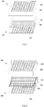
- the array substrate 100 includes a base substrate 101, a second touch driving electrode (shutter bar) 104, a first insulating layer 105, an active layer 106, a gate insulating layer 107, a gate electrode 108, a second insulating layer 109, a source-drain electrode 110, a third insulating layer 111, a first touch driving electrode 102, a passivation layer 112, pixel electrodes 113 and a first alignment layer 114 arranged on a side of the base substrate 101 facing toward the color film substrate 200, and a second touch sensitive electrode 103 and a first polarizer 115 arranged on a side of the base substrate 101 facing away from the color film substrate 200.
- the color film substrate 200 includes a base substrate 201, a black matrix 203, a color filter layer 204 and a second alignment layer 205 arranged on a side of the base substrate 201 facing toward the array substrate 100, and a first touch sensitive electrode 202 and a second polarizer 206 arranged on a side of the base substrate 201 facing away from the array substrate 100.
- a mutual capacitance is generated between the first touch driving electrode 102 and the first touch sensitive electrode 202.
- a mutual capacitance is generated between the second touch driving electrode 104 and the second touch sensitive electrode 103. Therefore, the double-sided touch is achieved.
- a touch display apparatus is further provided according to one embodiment of the disclosure, which includes the touch display panel described above.
- the user can perform a touch operation with a finger on a back side of the touch display apparatus, which has no effect on a front view and cause a flexible usage effect.
- the touch display apparatus may also be a touch display apparatus with a double-sided display function, that is, the display function and the touch function can be achieved on the double sides of the touch display apparatus.
- a method for driving a touch display panel is further provided according to one embodiment of the disclosure, which is applied to the touch display panel according to any one of the embodiments described above.
- the driving method includes:
- the touch driving electrode includes a first touch driving electrode and a second touch driving electrode.
- a mutual capacitance is generated between the first touch driving electrode and the first touch sensitive electrode.
- a mutual capacitance is generated between the second touch driving electrode and the second touch sensitive electrode. That is, one touch structure is defined by the first touch driving electrode and the first touch sensitive electrode; and one touch structure is defined by the second touch driving electrode and the second touch sensitive electrode.
- the step of applying a touch driving signal to the touch driving electrode includes:
- one touch structure is defined by the first touch driving electrode and the first touch sensitive electrode and one touch structure is defined by the second touch driving electrode and the second touch sensitive electrode
- only one touch structure may be used and the other touch structure is closed at the same time, thereby achieving the single-sided touch mode; optionally, the two touch structures are used at the same time, thereby achieving the double-sided touch mode.
- a touch driving signal may be applied to only the first touch driving electrode, rather than the second touch driving electrode.
- a touch driving signal is applied to the first touch driving electrode and the second touch driving electrode at the same time.
- the touch driving signal applied to the first touch driving electrode and the second touch driving electrode may be the same or may also be different.
- the first touch driving electrode may be electrically connected to the second touch driving electrode, in order to reduce resistances of the touch driving electrodes.
- the same touch driving signal is applied to the first touch driving electrode and the second touch driving electrode.
- the method according to the embodiment of the disclosure further includes: supplying a touch sensitive signal to the first touch sensitive electrode and the second touch sensitive electrode in a touch period, supplying a zero voltage to the first touch sensitive electrode and the second touch sensitive electrode in a display period, to eliminate static electricity on the first touch sensitive electrode and the second touch sensitive electrode.
Landscapes
- Engineering & Computer Science (AREA)
- Physics & Mathematics (AREA)
- Theoretical Computer Science (AREA)
- General Engineering & Computer Science (AREA)
- General Physics & Mathematics (AREA)
- Human Computer Interaction (AREA)
- Nonlinear Science (AREA)
- Crystallography & Structural Chemistry (AREA)
- Optics & Photonics (AREA)
- Chemical & Material Sciences (AREA)
- Mathematical Physics (AREA)
- Microelectronics & Electronic Packaging (AREA)
- Position Input By Displaying (AREA)
Claims (11)
- Berührungsanzeigetafel, umfassend:ein Array-Substrat (100) und ein Zellenausrichtungssubstrat (200), die gegenüberliegend angeordnet sind, eine Berührungsansteuerungselektrode, eine erste berührungsempfindliche Elektrode (202), und eine zweite berührungsempfindliche Elektrode (103);wobei die erste berührungsempfindliche Elektrode (202) auf dem Zellenausrichtungssubstrat (200) angeordnet ist und die zweite berührungsempfindliche Elektrode (103) auf dem Array-Substrat (100) angeordnet ist; wobei die Berührungsansteuerungselektrode zwischen der ersten berührungsempfindlichen Elektrode (202) und der zweiten berührungsempfindlichen Elektrode (103) angeordnet ist, dergestalt, dass zwischen der Berührungsansteuerungselektrode und jeder der ersten berührungsempfindlichen Elektrode (202) und der zweiten berührungsempfindlichen Elektrode (103) wechselseitige Kapazitäten erzeugt werden;wobei sowohl das Array-Substrat (100) als auch das Zellenausrichtungssubstrat (200) ein Basissubstrat (101/201) umfasst; wobei die Berührungsansteuerungselektrode auf einer Seite des Basissubstrats (101) des Array-Substrats (100) angeordnet ist, die dem Zellenausrichtungssubstrat (200) zugewandt ist; wobei die erste berührungsempfindliche Elektrode (202) auf einer Seite des Basissubstrats (201) des Zellenausrichtungssubstrats (200) angeordnet ist, die dem Array-Substrat (100) zugewandt ist oder von dem Array-Substrat (100) fort weist; wobei die zweite berührungsempfindliche Elektrode (103) auf einer Seite des Basissubstrats (101) des Array-Substrats (100) angeordnet ist, die dem Zellenausrichtungssubstrat (200) zugewandt ist oder von dem Zellenausrichtungssubstrat (200) fort weist;wobei das Array-Substrat (100) des Weiteren eine gemeinsame Elektrode umfasst; wobei die Berührungsansteuerungselektrode eine erste Berührungsansteuerungselektrode (102) umfasst;wobei die erste Berührungsansteuerungselektrode (102) und die gemeinsame Elektrode aus dem gleichen Material bestehen und in derselben Schicht angeordnet sind;wobei die Berührungsansteuerungselektrode des Weiteren eine zweite Berührungsansteuerungselektrode (104) umfasst; wobei die zweite Berührungsansteuerungselektrode (104) in einer anderen Schicht angeordnet ist als die erste Berührungsansteuerungselektrode (102), dergestalt, dass eine wechselseitige Kapazität zwischen der ersten Berührungsansteuerungselektrode (102) und der ersten berührungsempfindlichen Elektrode (202) erzeugt wird und eine wechselseitige Kapazität zwischen der zweiten Berührungsansteuerungselektrode (104) und der zweiten berührungsempfindlichen Elektrode (103) erzeugt wird;wobei das Array-Substrat (100) des Weiteren einen Dünnfilmtransistor umfasst; wobei die zweite Berührungsansteuerungselektrode (104) eine Verschlussleiste zwischen dem Dünnfilmtransistor und dem Basissubstrat (101) des Array-Substrats (100) ist und zum Abschirmen eines Kanals des Dünnfilmtransistors ausgebildet ist, um zu verhindern, dass Licht den Kanal des Dünnfilmtransistors beleuchtet.
- Berührungsanzeigetafel nach Anspruch 1, wobei die erste Berührungsansteuerungselektrode (102) elektrisch mit der zweiten Berührungsansteuerungselektrode (104) verbunden ist.
- Berührungsanzeigetafel nach Anspruch 2, wobei die erste Berührungsansteuerungselektrode (102) mehrere erste Ansteuerungs-Teilelektroden umfasst, die parallel zueinander verlaufen; wobei die zweite Berührungsansteuerungselektrode (104) mehrere zweite Ansteuerungs-Teilelektroden umfasst, die parallel zueinander verlaufen; wobei die ersten Ansteuerungs-Teilelektroden jeweils elektrisch mit den zweiten Ansteuerungs-Teilelektroden verbunden sind.
- Berührungsanzeigetafel nach Anspruch 3, wobei die erste berührungsempfindliche Elektrode (202) mehrere erste empfindliche Teilelektroden (31) umfasst, die parallel zueinander verlaufen; wobei die zweite berührungsempfindliche Elektrode (103) mehrere zweite empfindliche Teilelektroden (32) umfasst, die parallel zueinander verlaufen; wobei die Anzahl und Anordnung der ersten empfindlichen Teilelektroden (31) die gleichen sind wie die der zweiten empfindlichen Teilelektroden (32); wobei die ersten empfindlichen Teilelektroden (31) den zweiten empfindlichen Teilelektroden (32) in einer Eins-zu-eins-Beziehung entsprechen; und wobei jede der ersten empfindlichen Teilelektroden (31) mit der entsprechenden der zweiten empfindlichen Teilelektroden (32) verbunden ist; und wobei die ersten empfindlichen Teilelektroden (31) und die ersten Ansteuerungs-Teilelektroden in verschiedenen Ebenen angeordnet sind und die ersten empfindlichen Teilelektroden (31) nicht parallel zu den ersten Ansteuerungs-Teilelektroden verlaufen; wobei eine gegenseitige Kapazität an jedem Überlappungsabschnitt der ersten empfindlichen Teilelektroden (31) und der ersten Ansteuerungs-Teilelektroden erzeugt wird; wobei die zweiten empfindlichen Teilelektroden und die zweiten Ansteuerungs-Teilelektroden in verschiedenen Ebenen angeordnet sind und die zweiten empfindlichen Teilelektroden (32) nicht parallel zu den zweiten Ansteuerungs-Teilelektroden verlaufen; wobei eine gegenseitige Kapazität an jedem Überlappungsabschnitt der zweiten empfindlichen Teilelektroden (32) und der zweiten Ansteuerungs-Teilelektroden erzeugt wird.
- Berührungsanzeigetafel nach Anspruch 1, wobei die erste berührungsempfindliche Elektrode (202) mehrere erste empfindliche Teilelektroden (31) umfasst, die parallel zueinander verlaufen; wobei die zweite berührungsempfindliche Elektrode (103) mehrere zweite empfindliche Teilelektroden (32) umfasst, die parallel zueinander verlaufen; wobei die Anzahl und Anordnung der ersten empfindlichen Teilelektroden (31) die gleichen sind wie die der zweiten empfindlichen Teilelektroden (32); wobei die ersten empfindlichen Teilelektroden (31) den zweiten empfindlichen Teilelektroden (32) in einer Eins-zu-eins-Beziehung entsprechen; und wobei jede der ersten empfindlichen Teilelektroden (31) mit der entsprechenden der zweiten empfindlichen Teilelektroden (32) verbunden ist.
- Berührungsanzeigetafel nach Anspruch 5, wobei jede der ersten empfindlichen Teilelektroden (31) mit der entsprechenden der zweiten empfindlichen Teilelektroden (32) über eine flexible Leiterplatte (33) auf einer Seite des Zellenausrichtungssubstrats (200), eine flexible Leiterplatte (34) auf einer Seite des Array-Substrats (100), und einen Verbindungsdraht (35) zum Verbinden der beiden flexiblen Leiterplatten verbunden ist; wobei der Verbindungsdraht (35) mehrere Verbindungs-Teildrähte (351) umfasst und jeder der Verbindungs-Teildrähte (351) einer der ersten empfindlichen Teilelektroden (31) und einer der zweiten empfindlichen Teilelektroden (32) entspricht.
- Verfahren zum Ansteuern der Berührungsanzeigetafel nach einem der Ansprüche 1 bis 6, umfassend:Anlegen eines Berührungsansteuerungssignals an die Berührungsansteuerungselektrode; undDetektieren eines Berührungsempfindlichkeitssignals, das durch Koppeln der wechselseitigen Kapazität zwischen der ersten berührungsempfindlichen Elektrode (202) und/oder der zweiten berührungsempfindlichen Elektrode (103) mit der Berührungsansteuerungselektrode erzeugt wird, und Bestimmen von Berührungspositionsinformationen gemäß der Änderung des Berührungsempfindlichkeitssignals.
- Verfahren nach Anspruch 7, wobei die Berührungsansteuerungselektrode eine erste Berührungsansteuerungselektrode (102) und eine zweite Berührungsansteuerungselektrode (104) umfasst; wobei eine wechselseitige Kapazität zwischen der ersten Berührungsansteuerungselektrode (102) und der ersten berührungsempfindlichen Elektrode ( 202 ) erzeugt wird; wobei eine wechselseitige Kapazität zwischen der zweiten Berührungsansteuerungselektrode (104) und der zweiten berührungsempfindlichen Elektrode (103) erzeugt wird; wobei der Schritt des Anlegens des Berührungsansteuerungssignals an die Berührungsansteuerungselektrode Folgendes umfasst:Anlegen eines einzelnen Berührungsansteuerungssignals an die erste Berührungsansteuerungselektrode (102) oder die zweite Berührungsansteuerungselektrode (104); oderAnlegen desselben Berührungsansteuerungssignals oder anderer Berührungsansteuerungssignale an die erste Berührungsansteuerungselektrode (102) und die zweite Berührungsansteuerungselektrode (104).
- Verfahren nach Anspruch 7, des Weiteren umfassend:Anlegen eines Berührungsempfindlichkeitssignals an die erste berührungsempfindliche Elektrode (202) und die zweite berührungsempfindliche Elektrode (103) in einem Berührungszeitraum, undAnlegen einer Nullspannung an die erste berührungsempfindliche Elektrode (202) und die zweite berührungsempfindliche Elektrode (103) in einem Anzeigezeitraum, um statische Elektrizität an der ersten berührungsempfindlichen Elektrode (202) und der zweiten berührungsempfindlichen Elektrode (103) zu beseitigen.
- Berührungsanzeigetafel, umfassend: ein Array-Substrat (100) und ein Zellenausrichtungssubstrat (200), die gegenüberliegend angeordnet sind, eine erste Berührungsansteuerungselektrode (102), eine zweite Berührungsansteuerungselektrode (104), eine erste berührungsempfindliche Elektrode (202) und eine zweite berührungsempfindliche Elektrode (103);
wobei die erste berührungsempfindliche Elektrode (202) auf dem Zellenausrichtungssubstrat (200) angeordnet ist und die zweite berührungsempfindliche Elektrode (103) auf dem Array-Substrat (100) angeordnet ist;
wobei die erste Berührungsansteuerungselektrode (102) und die zweite Berührungsansteuerungselektrode (104) in verschiedenen Schichten zwischen der ersten berührungsempfindlichen Elektrode (202) und der zweiten berührungsempfindlichen Elektrode (103) angeordnet sind; wobei die erste Berührungsansteuerungselektrode (102) und die erste berührungsempfindliche Elektrode (202) eine erste Berührungsstruktur definieren; wobei die zweite Berührungsansteuerungselektrode (104) und die zweite berührungsempfindliche Elektrode (103) eine zweite Berührungsstruktur definieren; und
die erste Berührungsstruktur und die zweite Berührungsstruktur sich jeweils auf zwei Seiten der Berührungsanzeigetafel befinden;
dadurch gekennzeichnet, dass das Array-Substrat (100) ein Basissubstrat (101) und einen Dünnfilmtransistor umfasst; und
die zweite Berührungsansteuerungselektrode (104) eine Verschlussleiste zwischen dem Dünnfilmtransistor und dem Basissubstrat (101) des Array-Substrats (100) ist und zum Abschirmen eines Kanals des Dünnfilmtransistors ausgebildet ist, um zu verhindern, dass Licht den Kanal des Dünnfilmtransistors beleuchtet. - Verfahren zum Steuern der Berührungsanzeigetafel nach Anspruch 10, umfasssend:Beurteilen, ob sich die Berührungsanzeigetafel in einem einseitigen Berührungsmodus oder einem doppelseitigen Berührungsmodus befindet;wenn sich die Berührungsanzeigetafel im einseitigen Berührungsmodus befindet, Beurteilen, ob die erste Berührungsstruktur oder die zweite Berührungsstruktur für eine Berührungsoperation ausgewählt ist;wenn die erste Berührungsstruktur für die Berührungsoperation ausgewählt wird, Schließen der zweiten Berührungsstruktur, Anlegen eines Berührungsansteuerungssignals an die erste Berührungsansteuerungselektrode (102), Detektieren eines ersten Berührungsempfindlichkeitssignals, das durch Koppeln der wechselseitigen Kapazität zwischen der ersten berührungsempfindlichen Elektrode (202) und der ersten Berührungsansteuerungselektrode (102) erzeugt wird, und Bestimmen von Berührungspositionsinformationen gemäß der Änderung des ersten Berührungsempfindlichkeitssignals; wenn die zweite Berührungsstruktur für die Berührungsoperation ausgewählt wird, Schließen der ersten Berührungsstruktur, Anlegen eines Berührungsansteuerungssignals an die zweite Berührungsansteuerungselektrode (104), Detektieren eines zweiten Berührungssensorsignals, das durch Koppeln der wechselseitigen Kapazität zwischen der zweiten Berührungsansteuerungselektrode (103) und der zweiten Berührungsansteuerungselektrode (104) erzeugt wird, und Bestimmen von Berührungspositionsinformationen gemäß der Änderung des zweiten Berührungssensorsignals; wenn sich die Berührungsanzeigetafel im doppelseitigen Berührungsmodus befindet,
gleichzeitiges Anlegen eines Berührungsansteuerungssignals an die erste Berührungsansteuerungselektrode (102) und die zweite Berührungsansteuerungselektrode (104);Detektieren eines ersten Berührungsempfindlichkeitssignals, das durch Koppeln der wechselseitigen Kapazität zwischen der ersten berührungsempfindlichen Elektrode (202) und der ersten Berührungsansteuerungselektrode (102) erzeugt wird, und Detektieren eines zweiten Berührungsempfindlichkeitssignals, das durch Koppeln der wechselseitigen Kapazität zwischen der zweiten berührungsempfindlichen Elektrode (103) und der zweiten Berührungsansteuerungselektrode (104) erzeugt wird; und Bestimmen von Berührungspositionsinformationen gemäß der Änderung des ersten Berührungsempfindlichkeitssignals und des zweiten Berührungsempfindlichkeitssignals.
Applications Claiming Priority (2)
| Application Number | Priority Date | Filing Date | Title |
|---|---|---|---|
| CN201410781935.8A CN104407761A (zh) | 2014-12-16 | 2014-12-16 | 触摸显示面板及其驱动方法、触摸显示装置 |
| PCT/CN2015/083641 WO2016095504A1 (zh) | 2014-12-16 | 2015-07-09 | 触摸显示面板及其驱动方法、触摸显示装置 |
Publications (3)
| Publication Number | Publication Date |
|---|---|
| EP3236342A1 EP3236342A1 (de) | 2017-10-25 |
| EP3236342A4 EP3236342A4 (de) | 2018-07-25 |
| EP3236342B1 true EP3236342B1 (de) | 2020-02-19 |
Family
ID=52645396
Family Applications (1)
| Application Number | Title | Priority Date | Filing Date |
|---|---|---|---|
| EP15869015.6A Active EP3236342B1 (de) | 2014-12-16 | 2015-07-09 | Berührungsanzeigetafel und ansteuerungsverfahren dafür sowie berührungsanzeigevorrichtung |
Country Status (4)
| Country | Link |
|---|---|
| US (1) | US10268307B2 (de) |
| EP (1) | EP3236342B1 (de) |
| CN (1) | CN104407761A (de) |
| WO (1) | WO2016095504A1 (de) |
Families Citing this family (9)
| Publication number | Priority date | Publication date | Assignee | Title |
|---|---|---|---|---|
| CN104407761A (zh) | 2014-12-16 | 2015-03-11 | 京东方科技集团股份有限公司 | 触摸显示面板及其驱动方法、触摸显示装置 |
| CN106708339B (zh) * | 2015-10-26 | 2023-12-15 | 京东方科技集团股份有限公司 | 一种内嵌式触摸屏、其驱动方法及显示装置 |
| CN106325598B (zh) * | 2016-08-19 | 2024-05-31 | 合肥京东方光电科技有限公司 | 触控显示面板及其制作方法、显示装置 |
| CN107066162B (zh) * | 2017-05-27 | 2020-03-17 | 上海天马微电子有限公司 | 一种显示面板及显示装置 |
| CN109785746B (zh) * | 2018-12-28 | 2022-02-01 | 友达光电(昆山)有限公司 | 一种显示装置 |
| US11874537B2 (en) | 2018-12-28 | 2024-01-16 | AU Optronics (Kunshan) Co., Ltd. | Display device |
| CN113760114B (zh) | 2020-06-03 | 2024-03-01 | 京东方科技集团股份有限公司 | 触控面板及其驱动方法、显示装置 |
| JP2022153047A (ja) * | 2021-03-29 | 2022-10-12 | 株式会社ジャパンディスプレイ | センサモジュール及びそれを備えたタッチパネル |
| CN115241208A (zh) * | 2022-07-08 | 2022-10-25 | 武汉华星光电技术有限公司 | 显示面板 |
Family Cites Families (17)
| Publication number | Priority date | Publication date | Assignee | Title |
|---|---|---|---|---|
| US5392058A (en) * | 1991-05-15 | 1995-02-21 | Sharp Kabushiki Kaisha | Display-integrated type tablet device |
| US8471822B2 (en) * | 2006-09-06 | 2013-06-25 | Apple Inc. | Dual-sided track pad |
| US8026903B2 (en) | 2007-01-03 | 2011-09-27 | Apple Inc. | Double-sided touch sensitive panel and flex circuit bonding |
| US8482545B2 (en) * | 2008-10-02 | 2013-07-09 | Wacom Co., Ltd. | Combination touch and transducer input system and method |
| CN101996031A (zh) * | 2009-08-25 | 2011-03-30 | 鸿富锦精密工业(深圳)有限公司 | 具有触摸输入功能的电子装置及其触摸输入方法 |
| US8810524B1 (en) * | 2009-11-20 | 2014-08-19 | Amazon Technologies, Inc. | Two-sided touch sensor |
| JP5726111B2 (ja) * | 2012-03-14 | 2015-05-27 | 株式会社ジャパンディスプレイ | 画像表示装置 |
| TW201346662A (zh) * | 2012-05-09 | 2013-11-16 | Wintek Corp | 觸控顯示裝置及其驅動方法 |
| CN103425310A (zh) * | 2012-05-22 | 2013-12-04 | 联胜(中国)科技有限公司 | 触控显示装置及其驱动方法 |
| CN104216578A (zh) | 2013-05-30 | 2014-12-17 | 京东方科技集团股份有限公司 | 一种触摸面板及显示装置 |
| CN103677476B (zh) | 2013-12-13 | 2016-04-13 | 京东方科技集团股份有限公司 | 触控装置及其驱动方法 |
| CN103699269B (zh) * | 2013-12-27 | 2017-02-01 | 京东方科技集团股份有限公司 | 一种双面触摸显示装置 |
| CN103995617B (zh) * | 2014-05-30 | 2018-09-07 | 京东方科技集团股份有限公司 | 内嵌式触控显示面板、其操作方法及显示装置 |
| CN104090696B (zh) * | 2014-06-19 | 2018-01-09 | 京东方科技集团股份有限公司 | 双面触控的显示面板、装置及驱动方法 |
| CN104465703B (zh) * | 2014-11-21 | 2019-02-12 | 上海天马有机发光显示技术有限公司 | 一种显示面板及其制造方法和显示装置 |
| CN204242158U (zh) * | 2014-12-16 | 2015-04-01 | 京东方科技集团股份有限公司 | 触摸显示面板和触摸显示装置 |
| CN104407761A (zh) | 2014-12-16 | 2015-03-11 | 京东方科技集团股份有限公司 | 触摸显示面板及其驱动方法、触摸显示装置 |
-
2014
- 2014-12-16 CN CN201410781935.8A patent/CN104407761A/zh active Pending
-
2015
- 2015-07-09 US US15/306,145 patent/US10268307B2/en active Active
- 2015-07-09 EP EP15869015.6A patent/EP3236342B1/de active Active
- 2015-07-09 WO PCT/CN2015/083641 patent/WO2016095504A1/zh not_active Ceased
Non-Patent Citations (1)
| Title |
|---|
| None * |
Also Published As
| Publication number | Publication date |
|---|---|
| US10268307B2 (en) | 2019-04-23 |
| EP3236342A1 (de) | 2017-10-25 |
| EP3236342A4 (de) | 2018-07-25 |
| WO2016095504A1 (zh) | 2016-06-23 |
| CN104407761A (zh) | 2015-03-11 |
| US20170045995A1 (en) | 2017-02-16 |
Similar Documents
| Publication | Publication Date | Title |
|---|---|---|
| EP3236342B1 (de) | Berührungsanzeigetafel und ansteuerungsverfahren dafür sowie berührungsanzeigevorrichtung | |
| JP5797897B2 (ja) | タッチスクリーンパネル一体型液晶表示装置 | |
| KR101993220B1 (ko) | 터치스크린 일체형 표시장치 | |
| EP2703969B1 (de) | Kapazitive In-Zellen-Berührungsbildschirmtafel und Anzeigevorrichtung | |
| EP2698689B1 (de) | Berührungstafel in der Zelle | |
| KR101623776B1 (ko) | 터치 디스플레이 드라이버 집적회로 및 터치 표시장치 | |
| US9965111B2 (en) | In-cell touch screen and display apparatus | |
| CN103576360B (zh) | 带触摸传感器的液晶显示装置以及电子设备 | |
| US10185170B2 (en) | Display device | |
| KR101360782B1 (ko) | 터치 스크린 일체형 표시장치 | |
| US20140204049A1 (en) | Display apparatus with touch sensing function | |
| US20150268762A1 (en) | In-cell touch panel and display device | |
| US10635242B2 (en) | Display device with touch detection function, method for driving display device with touch detection function, and electronic apparatus | |
| US10185423B2 (en) | Plug-in touch display device and an electronic device | |
| KR20140060963A (ko) | 터치 스크린 일체형 디스플레이 장치 | |
| JP2014026218A (ja) | タッチパネル付表示装置 | |
| US10095359B2 (en) | Touch detection device, display device with touch detecting function, and electronic apparatus | |
| JP6869786B2 (ja) | 表示装置及び方法 | |
| KR20130134007A (ko) | 터치 센싱 장치와 그 구동 방법 | |
| US10401669B2 (en) | Touch display panel having conductive structure and touch display device | |
| US20150029413A1 (en) | Touch display apparatus | |
| JP2017134249A (ja) | 表示装置 | |
| CN204242158U (zh) | 触摸显示面板和触摸显示装置 | |
| US20250383729A1 (en) | Display apparatus with an integrated touch screen | |
| KR20160093442A (ko) | 터치패널 및 이를 포함하는 터치표시장치 |
Legal Events
| Date | Code | Title | Description |
|---|---|---|---|
| STAA | Information on the status of an ep patent application or granted ep patent |
Free format text: STATUS: THE INTERNATIONAL PUBLICATION HAS BEEN MADE |
|
| PUAI | Public reference made under article 153(3) epc to a published international application that has entered the european phase |
Free format text: ORIGINAL CODE: 0009012 |
|
| STAA | Information on the status of an ep patent application or granted ep patent |
Free format text: STATUS: REQUEST FOR EXAMINATION WAS MADE |
|
| 17P | Request for examination filed |
Effective date: 20161025 |
|
| AK | Designated contracting states |
Kind code of ref document: A1 Designated state(s): AL AT BE BG CH CY CZ DE DK EE ES FI FR GB GR HR HU IE IS IT LI LT LU LV MC MK MT NL NO PL PT RO RS SE SI SK SM TR |
|
| AX | Request for extension of the european patent |
Extension state: BA ME |
|
| DAV | Request for validation of the european patent (deleted) | ||
| DAX | Request for extension of the european patent (deleted) | ||
| A4 | Supplementary search report drawn up and despatched |
Effective date: 20180622 |
|
| RIC1 | Information provided on ipc code assigned before grant |
Ipc: G06F 3/044 20060101AFI20180618BHEP Ipc: G06F 3/041 20060101ALI20180618BHEP Ipc: G02F 1/1333 20060101ALI20180618BHEP |
|
| GRAP | Despatch of communication of intention to grant a patent |
Free format text: ORIGINAL CODE: EPIDOSNIGR1 |
|
| STAA | Information on the status of an ep patent application or granted ep patent |
Free format text: STATUS: GRANT OF PATENT IS INTENDED |
|
| RIC1 | Information provided on ipc code assigned before grant |
Ipc: G06F 3/044 20060101AFI20190823BHEP Ipc: G02F 1/1333 20060101ALI20190823BHEP Ipc: G06F 3/041 20060101ALI20190823BHEP |
|
| INTG | Intention to grant announced |
Effective date: 20190910 |
|
| GRAS | Grant fee paid |
Free format text: ORIGINAL CODE: EPIDOSNIGR3 |
|
| GRAA | (expected) grant |
Free format text: ORIGINAL CODE: 0009210 |
|
| STAA | Information on the status of an ep patent application or granted ep patent |
Free format text: STATUS: THE PATENT HAS BEEN GRANTED |
|
| AK | Designated contracting states |
Kind code of ref document: B1 Designated state(s): AL AT BE BG CH CY CZ DE DK EE ES FI FR GB GR HR HU IE IS IT LI LT LU LV MC MK MT NL NO PL PT RO RS SE SI SK SM TR |
|
| REG | Reference to a national code |
Ref country code: CH Ref legal event code: EP |
|
| REG | Reference to a national code |
Ref country code: DE Ref legal event code: R096 Ref document number: 602015047518 Country of ref document: DE |
|
| REG | Reference to a national code |
Ref country code: AT Ref legal event code: REF Ref document number: 1235703 Country of ref document: AT Kind code of ref document: T Effective date: 20200315 |
|
| REG | Reference to a national code |
Ref country code: IE Ref legal event code: FG4D |
|
| REG | Reference to a national code |
Ref country code: NL Ref legal event code: MP Effective date: 20200219 |
|
| PG25 | Lapsed in a contracting state [announced via postgrant information from national office to epo] |
Ref country code: FI Free format text: LAPSE BECAUSE OF FAILURE TO SUBMIT A TRANSLATION OF THE DESCRIPTION OR TO PAY THE FEE WITHIN THE PRESCRIBED TIME-LIMIT Effective date: 20200219 Ref country code: NO Free format text: LAPSE BECAUSE OF FAILURE TO SUBMIT A TRANSLATION OF THE DESCRIPTION OR TO PAY THE FEE WITHIN THE PRESCRIBED TIME-LIMIT Effective date: 20200519 Ref country code: RS Free format text: LAPSE BECAUSE OF FAILURE TO SUBMIT A TRANSLATION OF THE DESCRIPTION OR TO PAY THE FEE WITHIN THE PRESCRIBED TIME-LIMIT Effective date: 20200219 |
|
| REG | Reference to a national code |
Ref country code: LT Ref legal event code: MG4D |
|
| PG25 | Lapsed in a contracting state [announced via postgrant information from national office to epo] |
Ref country code: IS Free format text: LAPSE BECAUSE OF FAILURE TO SUBMIT A TRANSLATION OF THE DESCRIPTION OR TO PAY THE FEE WITHIN THE PRESCRIBED TIME-LIMIT Effective date: 20200619 Ref country code: HR Free format text: LAPSE BECAUSE OF FAILURE TO SUBMIT A TRANSLATION OF THE DESCRIPTION OR TO PAY THE FEE WITHIN THE PRESCRIBED TIME-LIMIT Effective date: 20200219 Ref country code: LV Free format text: LAPSE BECAUSE OF FAILURE TO SUBMIT A TRANSLATION OF THE DESCRIPTION OR TO PAY THE FEE WITHIN THE PRESCRIBED TIME-LIMIT Effective date: 20200219 Ref country code: SE Free format text: LAPSE BECAUSE OF FAILURE TO SUBMIT A TRANSLATION OF THE DESCRIPTION OR TO PAY THE FEE WITHIN THE PRESCRIBED TIME-LIMIT Effective date: 20200219 Ref country code: BG Free format text: LAPSE BECAUSE OF FAILURE TO SUBMIT A TRANSLATION OF THE DESCRIPTION OR TO PAY THE FEE WITHIN THE PRESCRIBED TIME-LIMIT Effective date: 20200519 Ref country code: GR Free format text: LAPSE BECAUSE OF FAILURE TO SUBMIT A TRANSLATION OF THE DESCRIPTION OR TO PAY THE FEE WITHIN THE PRESCRIBED TIME-LIMIT Effective date: 20200520 |
|
| PG25 | Lapsed in a contracting state [announced via postgrant information from national office to epo] |
Ref country code: NL Free format text: LAPSE BECAUSE OF FAILURE TO SUBMIT A TRANSLATION OF THE DESCRIPTION OR TO PAY THE FEE WITHIN THE PRESCRIBED TIME-LIMIT Effective date: 20200219 |
|
| PG25 | Lapsed in a contracting state [announced via postgrant information from national office to epo] |
Ref country code: LT Free format text: LAPSE BECAUSE OF FAILURE TO SUBMIT A TRANSLATION OF THE DESCRIPTION OR TO PAY THE FEE WITHIN THE PRESCRIBED TIME-LIMIT Effective date: 20200219 Ref country code: DK Free format text: LAPSE BECAUSE OF FAILURE TO SUBMIT A TRANSLATION OF THE DESCRIPTION OR TO PAY THE FEE WITHIN THE PRESCRIBED TIME-LIMIT Effective date: 20200219 Ref country code: EE Free format text: LAPSE BECAUSE OF FAILURE TO SUBMIT A TRANSLATION OF THE DESCRIPTION OR TO PAY THE FEE WITHIN THE PRESCRIBED TIME-LIMIT Effective date: 20200219 Ref country code: SM Free format text: LAPSE BECAUSE OF FAILURE TO SUBMIT A TRANSLATION OF THE DESCRIPTION OR TO PAY THE FEE WITHIN THE PRESCRIBED TIME-LIMIT Effective date: 20200219 Ref country code: ES Free format text: LAPSE BECAUSE OF FAILURE TO SUBMIT A TRANSLATION OF THE DESCRIPTION OR TO PAY THE FEE WITHIN THE PRESCRIBED TIME-LIMIT Effective date: 20200219 Ref country code: RO Free format text: LAPSE BECAUSE OF FAILURE TO SUBMIT A TRANSLATION OF THE DESCRIPTION OR TO PAY THE FEE WITHIN THE PRESCRIBED TIME-LIMIT Effective date: 20200219 Ref country code: CZ Free format text: LAPSE BECAUSE OF FAILURE TO SUBMIT A TRANSLATION OF THE DESCRIPTION OR TO PAY THE FEE WITHIN THE PRESCRIBED TIME-LIMIT Effective date: 20200219 Ref country code: PT Free format text: LAPSE BECAUSE OF FAILURE TO SUBMIT A TRANSLATION OF THE DESCRIPTION OR TO PAY THE FEE WITHIN THE PRESCRIBED TIME-LIMIT Effective date: 20200712 Ref country code: SK Free format text: LAPSE BECAUSE OF FAILURE TO SUBMIT A TRANSLATION OF THE DESCRIPTION OR TO PAY THE FEE WITHIN THE PRESCRIBED TIME-LIMIT Effective date: 20200219 |
|
| REG | Reference to a national code |
Ref country code: AT Ref legal event code: MK05 Ref document number: 1235703 Country of ref document: AT Kind code of ref document: T Effective date: 20200219 |
|
| REG | Reference to a national code |
Ref country code: DE Ref legal event code: R097 Ref document number: 602015047518 Country of ref document: DE |
|
| PLBE | No opposition filed within time limit |
Free format text: ORIGINAL CODE: 0009261 |
|
| STAA | Information on the status of an ep patent application or granted ep patent |
Free format text: STATUS: NO OPPOSITION FILED WITHIN TIME LIMIT |
|
| 26N | No opposition filed |
Effective date: 20201120 |
|
| PG25 | Lapsed in a contracting state [announced via postgrant information from national office to epo] |
Ref country code: IT Free format text: LAPSE BECAUSE OF FAILURE TO SUBMIT A TRANSLATION OF THE DESCRIPTION OR TO PAY THE FEE WITHIN THE PRESCRIBED TIME-LIMIT Effective date: 20200219 Ref country code: AT Free format text: LAPSE BECAUSE OF FAILURE TO SUBMIT A TRANSLATION OF THE DESCRIPTION OR TO PAY THE FEE WITHIN THE PRESCRIBED TIME-LIMIT Effective date: 20200219 |
|
| PG25 | Lapsed in a contracting state [announced via postgrant information from national office to epo] |
Ref country code: MC Free format text: LAPSE BECAUSE OF FAILURE TO SUBMIT A TRANSLATION OF THE DESCRIPTION OR TO PAY THE FEE WITHIN THE PRESCRIBED TIME-LIMIT Effective date: 20200219 Ref country code: PL Free format text: LAPSE BECAUSE OF FAILURE TO SUBMIT A TRANSLATION OF THE DESCRIPTION OR TO PAY THE FEE WITHIN THE PRESCRIBED TIME-LIMIT Effective date: 20200219 Ref country code: SI Free format text: LAPSE BECAUSE OF FAILURE TO SUBMIT A TRANSLATION OF THE DESCRIPTION OR TO PAY THE FEE WITHIN THE PRESCRIBED TIME-LIMIT Effective date: 20200219 |
|
| REG | Reference to a national code |
Ref country code: CH Ref legal event code: PL |
|
| GBPC | Gb: european patent ceased through non-payment of renewal fee |
Effective date: 20200709 |
|
| REG | Reference to a national code |
Ref country code: BE Ref legal event code: MM Effective date: 20200731 |
|
| PG25 | Lapsed in a contracting state [announced via postgrant information from national office to epo] |
Ref country code: LI Free format text: LAPSE BECAUSE OF NON-PAYMENT OF DUE FEES Effective date: 20200731 Ref country code: LU Free format text: LAPSE BECAUSE OF NON-PAYMENT OF DUE FEES Effective date: 20200709 Ref country code: FR Free format text: LAPSE BECAUSE OF NON-PAYMENT OF DUE FEES Effective date: 20200731 Ref country code: CH Free format text: LAPSE BECAUSE OF NON-PAYMENT OF DUE FEES Effective date: 20200731 Ref country code: GB Free format text: LAPSE BECAUSE OF NON-PAYMENT OF DUE FEES Effective date: 20200709 |
|
| PG25 | Lapsed in a contracting state [announced via postgrant information from national office to epo] |
Ref country code: BE Free format text: LAPSE BECAUSE OF NON-PAYMENT OF DUE FEES Effective date: 20200731 |
|
| PG25 | Lapsed in a contracting state [announced via postgrant information from national office to epo] |
Ref country code: IE Free format text: LAPSE BECAUSE OF NON-PAYMENT OF DUE FEES Effective date: 20200709 |
|
| PG25 | Lapsed in a contracting state [announced via postgrant information from national office to epo] |
Ref country code: TR Free format text: LAPSE BECAUSE OF FAILURE TO SUBMIT A TRANSLATION OF THE DESCRIPTION OR TO PAY THE FEE WITHIN THE PRESCRIBED TIME-LIMIT Effective date: 20200219 Ref country code: MT Free format text: LAPSE BECAUSE OF FAILURE TO SUBMIT A TRANSLATION OF THE DESCRIPTION OR TO PAY THE FEE WITHIN THE PRESCRIBED TIME-LIMIT Effective date: 20200219 Ref country code: CY Free format text: LAPSE BECAUSE OF FAILURE TO SUBMIT A TRANSLATION OF THE DESCRIPTION OR TO PAY THE FEE WITHIN THE PRESCRIBED TIME-LIMIT Effective date: 20200219 |
|
| PG25 | Lapsed in a contracting state [announced via postgrant information from national office to epo] |
Ref country code: MK Free format text: LAPSE BECAUSE OF FAILURE TO SUBMIT A TRANSLATION OF THE DESCRIPTION OR TO PAY THE FEE WITHIN THE PRESCRIBED TIME-LIMIT Effective date: 20200219 Ref country code: AL Free format text: LAPSE BECAUSE OF FAILURE TO SUBMIT A TRANSLATION OF THE DESCRIPTION OR TO PAY THE FEE WITHIN THE PRESCRIBED TIME-LIMIT Effective date: 20200219 |
|
| PGFP | Annual fee paid to national office [announced via postgrant information from national office to epo] |
Ref country code: DE Payment date: 20230720 Year of fee payment: 9 |
|
| REG | Reference to a national code |
Ref country code: DE Ref legal event code: R119 Ref document number: 602015047518 Country of ref document: DE |
|
| PG25 | Lapsed in a contracting state [announced via postgrant information from national office to epo] |
Ref country code: DE Free format text: LAPSE BECAUSE OF NON-PAYMENT OF DUE FEES Effective date: 20250201 |