EP3236558A1 - Drahtlose stromversorgung in dynamischen umgebungen - Google Patents
Drahtlose stromversorgung in dynamischen umgebungen Download PDFInfo
- Publication number
- EP3236558A1 EP3236558A1 EP17173137.5A EP17173137A EP3236558A1 EP 3236558 A1 EP3236558 A1 EP 3236558A1 EP 17173137 A EP17173137 A EP 17173137A EP 3236558 A1 EP3236558 A1 EP 3236558A1
- Authority
- EP
- European Patent Office
- Prior art keywords
- capacitors
- impedance
- microcontroller
- inductor
- coil
- Prior art date
- Legal status (The legal status is an assumption and is not a legal conclusion. Google has not performed a legal analysis and makes no representation as to the accuracy of the status listed.)
- Granted
Links
Images


Classifications
-
- H—ELECTRICITY
- H02—GENERATION; CONVERSION OR DISTRIBUTION OF ELECTRIC POWER
- H02J—ELECTRIC POWER NETWORKS; CIRCUIT ARRANGEMENTS OR SYSTEMS FOR SUPPLYING OR DISTRIBUTING ELECTRIC POWER; SYSTEMS FOR STORING ELECTRIC ENERGY
- H02J50/00—Circuit arrangements or systems for wireless supply or distribution of electric power
- H02J50/90—Circuit arrangements or systems for wireless supply or distribution of electric power involving detection or optimisation of position, e.g. alignment
-
- A—HUMAN NECESSITIES
- A61—MEDICAL OR VETERINARY SCIENCE; HYGIENE
- A61M—DEVICES FOR INTRODUCING MEDIA INTO, OR ONTO, THE BODY; DEVICES FOR TRANSDUCING BODY MEDIA OR FOR TAKING MEDIA FROM THE BODY; DEVICES FOR PRODUCING OR ENDING SLEEP OR STUPOR
- A61M60/00—Blood pumps; Devices for mechanical circulatory actuation; Balloon pumps for circulatory assistance
- A61M60/10—Location thereof with respect to the patient's body
- A61M60/122—Implantable pumps or pumping devices, i.e. the blood being pumped inside the patient's body
- A61M60/165—Implantable pumps or pumping devices, i.e. the blood being pumped inside the patient's body implantable in, on, or around the heart
- A61M60/178—Implantable pumps or pumping devices, i.e. the blood being pumped inside the patient's body implantable in, on, or around the heart drawing blood from a ventricle and returning the blood to the arterial system via a cannula external to the ventricle, e.g. left or right ventricular assist devices
-
- A—HUMAN NECESSITIES
- A61—MEDICAL OR VETERINARY SCIENCE; HYGIENE
- A61M—DEVICES FOR INTRODUCING MEDIA INTO, OR ONTO, THE BODY; DEVICES FOR TRANSDUCING BODY MEDIA OR FOR TAKING MEDIA FROM THE BODY; DEVICES FOR PRODUCING OR ENDING SLEEP OR STUPOR
- A61M60/00—Blood pumps; Devices for mechanical circulatory actuation; Balloon pumps for circulatory assistance
- A61M60/20—Type thereof
- A61M60/205—Non-positive displacement blood pumps
- A61M60/216—Non-positive displacement blood pumps including a rotating member acting on the blood, e.g. impeller
-
- A—HUMAN NECESSITIES
- A61—MEDICAL OR VETERINARY SCIENCE; HYGIENE
- A61M—DEVICES FOR INTRODUCING MEDIA INTO, OR ONTO, THE BODY; DEVICES FOR TRANSDUCING BODY MEDIA OR FOR TAKING MEDIA FROM THE BODY; DEVICES FOR PRODUCING OR ENDING SLEEP OR STUPOR
- A61M60/00—Blood pumps; Devices for mechanical circulatory actuation; Balloon pumps for circulatory assistance
- A61M60/50—Details relating to control
- A61M60/508—Electronic control means, e.g. for feedback regulation
- A61M60/515—Regulation using real-time patient data
- A61M60/523—Regulation using real-time patient data using blood flow data, e.g. from blood flow transducers
-
- A—HUMAN NECESSITIES
- A61—MEDICAL OR VETERINARY SCIENCE; HYGIENE
- A61M—DEVICES FOR INTRODUCING MEDIA INTO, OR ONTO, THE BODY; DEVICES FOR TRANSDUCING BODY MEDIA OR FOR TAKING MEDIA FROM THE BODY; DEVICES FOR PRODUCING OR ENDING SLEEP OR STUPOR
- A61M60/00—Blood pumps; Devices for mechanical circulatory actuation; Balloon pumps for circulatory assistance
- A61M60/50—Details relating to control
- A61M60/508—Electronic control means, e.g. for feedback regulation
- A61M60/538—Regulation using real-time blood pump operational parameter data, e.g. motor current
-
- A—HUMAN NECESSITIES
- A61—MEDICAL OR VETERINARY SCIENCE; HYGIENE
- A61M—DEVICES FOR INTRODUCING MEDIA INTO, OR ONTO, THE BODY; DEVICES FOR TRANSDUCING BODY MEDIA OR FOR TAKING MEDIA FROM THE BODY; DEVICES FOR PRODUCING OR ENDING SLEEP OR STUPOR
- A61M60/00—Blood pumps; Devices for mechanical circulatory actuation; Balloon pumps for circulatory assistance
- A61M60/80—Constructional details other than related to driving
- A61M60/855—Constructional details other than related to driving of implantable pumps or pumping devices
- A61M60/871—Energy supply devices; Converters therefor
- A61M60/873—Energy supply devices; Converters therefor specially adapted for wireless or transcutaneous energy transfer [TET], e.g. inductive charging
-
- H—ELECTRICITY
- H02—GENERATION; CONVERSION OR DISTRIBUTION OF ELECTRIC POWER
- H02J—ELECTRIC POWER NETWORKS; CIRCUIT ARRANGEMENTS OR SYSTEMS FOR SUPPLYING OR DISTRIBUTING ELECTRIC POWER; SYSTEMS FOR STORING ELECTRIC ENERGY
- H02J50/00—Circuit arrangements or systems for wireless supply or distribution of electric power
- H02J50/10—Circuit arrangements or systems for wireless supply or distribution of electric power using inductive coupling
- H02J50/12—Circuit arrangements or systems for wireless supply or distribution of electric power using inductive coupling of the resonant type
-
- A—HUMAN NECESSITIES
- A61—MEDICAL OR VETERINARY SCIENCE; HYGIENE
- A61M—DEVICES FOR INTRODUCING MEDIA INTO, OR ONTO, THE BODY; DEVICES FOR TRANSDUCING BODY MEDIA OR FOR TAKING MEDIA FROM THE BODY; DEVICES FOR PRODUCING OR ENDING SLEEP OR STUPOR
- A61M2205/00—General characteristics of the apparatus
- A61M2205/04—General characteristics of the apparatus implanted
-
- A—HUMAN NECESSITIES
- A61—MEDICAL OR VETERINARY SCIENCE; HYGIENE
- A61M—DEVICES FOR INTRODUCING MEDIA INTO, OR ONTO, THE BODY; DEVICES FOR TRANSDUCING BODY MEDIA OR FOR TAKING MEDIA FROM THE BODY; DEVICES FOR PRODUCING OR ENDING SLEEP OR STUPOR
- A61M2205/00—General characteristics of the apparatus
- A61M2205/35—Communication
- A61M2205/3507—Communication with implanted devices, e.g. external control
- A61M2205/3515—Communication with implanted devices, e.g. external control using magnetic means
-
- A—HUMAN NECESSITIES
- A61—MEDICAL OR VETERINARY SCIENCE; HYGIENE
- A61M—DEVICES FOR INTRODUCING MEDIA INTO, OR ONTO, THE BODY; DEVICES FOR TRANSDUCING BODY MEDIA OR FOR TAKING MEDIA FROM THE BODY; DEVICES FOR PRODUCING OR ENDING SLEEP OR STUPOR
- A61M2205/00—General characteristics of the apparatus
- A61M2205/35—Communication
- A61M2205/3507—Communication with implanted devices, e.g. external control
- A61M2205/3523—Communication with implanted devices, e.g. external control using telemetric means
-
- A—HUMAN NECESSITIES
- A61—MEDICAL OR VETERINARY SCIENCE; HYGIENE
- A61M—DEVICES FOR INTRODUCING MEDIA INTO, OR ONTO, THE BODY; DEVICES FOR TRANSDUCING BODY MEDIA OR FOR TAKING MEDIA FROM THE BODY; DEVICES FOR PRODUCING OR ENDING SLEEP OR STUPOR
- A61M2205/00—General characteristics of the apparatus
- A61M2205/35—Communication
- A61M2205/3546—Range
- A61M2205/3561—Range local, e.g. within room or hospital
-
- A—HUMAN NECESSITIES
- A61—MEDICAL OR VETERINARY SCIENCE; HYGIENE
- A61M—DEVICES FOR INTRODUCING MEDIA INTO, OR ONTO, THE BODY; DEVICES FOR TRANSDUCING BODY MEDIA OR FOR TAKING MEDIA FROM THE BODY; DEVICES FOR PRODUCING OR ENDING SLEEP OR STUPOR
- A61M2205/00—General characteristics of the apparatus
- A61M2205/82—Internal energy supply devices
- A61M2205/8237—Charging means
- A61M2205/8243—Charging means by induction
-
- A—HUMAN NECESSITIES
- A61—MEDICAL OR VETERINARY SCIENCE; HYGIENE
- A61M—DEVICES FOR INTRODUCING MEDIA INTO, OR ONTO, THE BODY; DEVICES FOR TRANSDUCING BODY MEDIA OR FOR TAKING MEDIA FROM THE BODY; DEVICES FOR PRODUCING OR ENDING SLEEP OR STUPOR
- A61M60/00—Blood pumps; Devices for mechanical circulatory actuation; Balloon pumps for circulatory assistance
- A61M60/10—Location thereof with respect to the patient's body
- A61M60/122—Implantable pumps or pumping devices, i.e. the blood being pumped inside the patient's body
- A61M60/126—Implantable pumps or pumping devices, i.e. the blood being pumped inside the patient's body implantable via, into, inside, in line, branching on, or around a blood vessel
- A61M60/148—Implantable pumps or pumping devices, i.e. the blood being pumped inside the patient's body implantable via, into, inside, in line, branching on, or around a blood vessel in line with a blood vessel using resection or like techniques, e.g. permanent endovascular heart assist devices
-
- H—ELECTRICITY
- H03—ELECTRONIC CIRCUITRY
- H03H—IMPEDANCE NETWORKS, e.g. RESONANT CIRCUITS; RESONATORS
- H03H7/00—Multiple-port networks comprising only passive electrical elements as network components
- H03H7/38—Impedance-matching networks
- H03H7/40—Automatic matching of load impedance to source impedance
-
- Y—GENERAL TAGGING OF NEW TECHNOLOGICAL DEVELOPMENTS; GENERAL TAGGING OF CROSS-SECTIONAL TECHNOLOGIES SPANNING OVER SEVERAL SECTIONS OF THE IPC; TECHNICAL SUBJECTS COVERED BY FORMER USPC CROSS-REFERENCE ART COLLECTIONS [XRACs] AND DIGESTS
- Y02—TECHNOLOGIES OR APPLICATIONS FOR MITIGATION OR ADAPTATION AGAINST CLIMATE CHANGE
- Y02T—CLIMATE CHANGE MITIGATION TECHNOLOGIES RELATED TO TRANSPORTATION
- Y02T10/00—Road transport of goods or passengers
- Y02T10/60—Other road transportation technologies with climate change mitigation effect
- Y02T10/70—Energy storage systems for electromobility, e.g. batteries
-
- Y—GENERAL TAGGING OF NEW TECHNOLOGICAL DEVELOPMENTS; GENERAL TAGGING OF CROSS-SECTIONAL TECHNOLOGIES SPANNING OVER SEVERAL SECTIONS OF THE IPC; TECHNICAL SUBJECTS COVERED BY FORMER USPC CROSS-REFERENCE ART COLLECTIONS [XRACs] AND DIGESTS
- Y02—TECHNOLOGIES OR APPLICATIONS FOR MITIGATION OR ADAPTATION AGAINST CLIMATE CHANGE
- Y02T—CLIMATE CHANGE MITIGATION TECHNOLOGIES RELATED TO TRANSPORTATION
- Y02T10/00—Road transport of goods or passengers
- Y02T10/60—Other road transportation technologies with climate change mitigation effect
- Y02T10/7072—Electromobility specific charging systems or methods for batteries, ultracapacitors, supercapacitors or double-layer capacitors
-
- Y—GENERAL TAGGING OF NEW TECHNOLOGICAL DEVELOPMENTS; GENERAL TAGGING OF CROSS-SECTIONAL TECHNOLOGIES SPANNING OVER SEVERAL SECTIONS OF THE IPC; TECHNICAL SUBJECTS COVERED BY FORMER USPC CROSS-REFERENCE ART COLLECTIONS [XRACs] AND DIGESTS
- Y02—TECHNOLOGIES OR APPLICATIONS FOR MITIGATION OR ADAPTATION AGAINST CLIMATE CHANGE
- Y02T—CLIMATE CHANGE MITIGATION TECHNOLOGIES RELATED TO TRANSPORTATION
- Y02T90/00—Enabling technologies or technologies with a potential or indirect contribution to GHG emissions mitigation
- Y02T90/10—Technologies relating to charging of electric vehicles
- Y02T90/14—Plug-in electric vehicles
Definitions
- Wireless power transfer using inductive coupling is becoming increasingly popular for consumer electronic devices.
- Commercial applications include wireless charging pads, electronic toothbrushes, induction cookers, and electric car battery chargers.
- None of these applications enable the range or geometric freedom that the term wireless power suggests.
- Charging pads and electric toothbrushes require that the device be placed very close to (or directly on top of) the charging pad. This is because the efficiency for traditional inductively coupled wireless power transfer systems drops off rapidly as the distance between the transmitter and receiver increases.
- Far-field wireless power transfer techniques use propagating electromagnetic waves and are capable of delivering power to a much larger volume of space.
- directionality For example, radio frequency (RF) broadcast methods-which transmit power in an omni-directional pattern-allow for power transfer anywhere in the coverage area.
- RF radio frequency
- Microwave systems with high gain antennas have been used to transfer power over several kilometers at efficiencies of over 90%.
- these systems suffer from the need for sophisticated tracking and alignment equipment to maintain a line of sight (point-to-point) connection.
- MCRs magnetically coupled resonators
- FIGURE 1 shows a diagram of a basic prior art wireless power system 90 using high-Q MCRs.
- a transmitter module 91 includes a single turn drive loop 93 and a multi-turn, spiral resonator or transmit coil (Tx coil) 94.
- Tx coil transmit coil
- an RF amplifier 92 drives current through the drive loop 93 at the transmitter module's 91 resonant frequency
- the resulting oscillating magnetic field excites the Tx coil 94.
- the Tx coil 94 stores energy in the same manner as a discrete LCR tank. This results in a large oscillating magnetic field in the vicinity of the Tx coil 94.
- a high-Q coil implies that more energy can be stored on the coil, which also results in greater magnetic flux density at a given point in space.
- the receiver module 95 is designed similarly. It includes a multi-turn, spiral resonator or receive coil (Rx coil) 96 and a single turn load loop 97, which is connected to an end device 98.
- the drive loop 93 and Tx coil 94 are magnetically coupled, and the load loop 97 and Rx coil 96 are magnetically coupled.
- the Tx coil 94 and the Rx coil 96 share a mutual inductance, which is a function of the geometry of the coils 94, 96 and the distance between them.
- the high-Q Tx and Rx coils 94, 96 form a single system of coupled resonators, which can efficiently transfer energy back and forth.
- the coupling coefficient between the Tx coil 94 and the Rx coil 96 is inversely proportional to the distance between the coils 94, 96.
- the coupling between the resonators 94, 96 decreases, and the frequency range for high efficiency power transfer narrows, until the optimal frequency converges to the fundamental frequency of the system (critical coupling).
- the resonators 94, 96 share more magnetic flux than is required to source the load.
- proper tuning techniques will enable near constant power transfer efficiency substantially within the entire over-coupled regime.
- the under-coupled regime In the under-coupled regime, the shared flux falls below a critical point. Below this point, the Tx coil 94 needs to emit more power to maintain the magnetic field than can be absorbed by the Rx coil 96. The result is that maximum efficiency cannot be achieved.
- Critical coupling is the point of transition between these two regimes and corresponds to the greatest range at which maximum efficiency can still be achieved.
- the under-coupled regime is still capable of wireless power transfer, but efficiency decreases rapidly as distance increases.
- a system takes advantage of the over-coupled regime to create a volume of space providing high efficiency power transfer between the transmitter module 91 and the receiver module 95, to wirelessly provide power to the end device 98.
- the system has also been found to provide range extension in the under-coupled region.
- the coupling coefficient between the Tx coil 94 and the Rx coil 96 depends of operating frequency.
- Prior art systems have proposed maintaining high efficiency in transferring energy in an MCR system using dynamic frequency tuning.
- the goal of dynamic frequency tuning is to automatically adjust the transmitter frequency (e.g., amplifier 92) to provide maximum power transfer efficiency between the Tx coil 94 and the Rx coil 96, e.g., as a user moves the Rx coil 96 within the system's working range.
- the mutual inductance between the Tx coil 94 and the Rx coil 96 is a function of the coil geometry and the distance and orientation between the coils 94, 96.
- ISM bands are allocated internationally for RF applications other than communication. ISM bands are currently used for applications such as RF heating and microwave ovens. Therefore, they are a natural choice for today's wireless power transfer systems.
- the ISM bands are governed in the U.S. by Part 18 of the Federal Communication Commission (FCC) rules.
- Part 15 of the FCC rules covers communication, even if the communication occurs in an ISM band.
- the field strength limits of Part 15 are more stringent than those of Part 18. Therefore, it may be desirable for wireless power transfer systems not to use the same band for power transfer and communication.
- the present invention includes methods and systems for an MCR power transfer system that dynamically adapts to variations in range, orientation, and load using both wide-band and fixed-frequency techniques.
- impedance matching methods and systems are disclosed that are suitable for fixed frequency operation, adaptive frequency tuning for wider bandwidth systems, and adaptive load matching techniques utilizing maximum power point tracking.
- An adaptive impedance matching wireless power transfer system includes a drive inductor configured to receive RF power, a first high-Q resonator coil inductively coupled to the drive inductor, a second high-Q resonator coil inductively coupled to the first high-Q resonator coil, and a load inductor inductively coupled to the second high-Q resonator coil.
- a first matching network for example a ⁇ -match network or an L-match network, is operably coupled to either the drive inductor or the load inductor, and is configured to selectively adjust the impedance between the drive or load inductor and the corresponding resonator coil.
- the drive or load inductor is the inductor for the first matching network.
- the drive inductor and/or the load inductor comprise a single loop.
- the first matching network is a ⁇ -match network with variable capacitances, which may be implemented, for example with one or more banks of capacitors configured in a switchable network.
- the switchable network is controlled with a microcontroller that selectively engages one or more of the capacitors in the bank of capacitors, to thereby adjust the impedance between the inductor and the resonator coil.
- the microcontroller adjusts the capacitors to maximize the forward transmission gain to the transmitter coil, for example using an exhaustive search through available switch combinations, using lookup tables correlating a measurable parameter of the system, or using a measured performance parameter of the system.
- system further comprises a second ⁇ -match network, wherein the first matching network is operably connected to the drive inductor and the second matching network is operably connected to the load inductor.
- system further comprises a rectifier with an active impedance matching circuit configured to receive direct current from the rectifier, and a microcontroller configured to monitor the direct current from the rectifier and to control the active impedance matching circuit to selectively harvest power from the rectifier and provide power to a device.
- An adaptive impedance matching wireless power transfer system includes a transmit side comprising a drive inductor configured to receive alternating current electric power from a power source at a fixed frequency, and a high-Q transmitter coil inductively coupled to the drive inductor, and a receive side comprising a high-Q receiver coil configured to be inductively coupled to the transmitter coil, and a load inductor inductively coupled to the receiver coil.
- a first matching network comprising a plurality of capacitors interconnected to form a switchable bank of capacitors, and a microcontroller operably connected to the switchable bank of capacitors, wherein the microcontroller is configured and operable to receive a measured operating parameter of the adaptive impedance matching wireless transfer system and to use the measured parameter to selectively adjust the impedance between either (i) the drive inductor and the transmitter coil, or (ii) the load inductor and the receiver coil.
- the measured parameter comprises an S-parameter or an RMS voltage measured in the system.
- the measured parameter is measured on the transmit side, and the microcontroller selectively adjusts the impedance between the drive inductor and the transmitter coil.
- the measured parameter is measured on the receive side, and the microcontroller selectively adjusts the impedance between the load inductor and the receiver coil.
- the measured parameter is measured on the receive side, and the microcontroller selectively adjusts the impedance between the drive inductor and the transmitter coil.
- the measured parameter is measured on the transmit side, and the microcontroller selectively adjusts the impedance between the load inductor and the receiver coil.
- the first matching network is operably connected to the transmit side, and further comprising a second matching network comprising a plurality of capacitors interconnected to form a switchable bank of capacitors, and a second microcontroller operably connected to the switchable bank of capacitors, wherein the second microcontroller is configured and operable to receive a measured operating parameter of the adaptive impedance matching wireless transfer system and to use the measured parameter to selectively adjust the impedance between the load inductor and the receiver coil.
- MCRs magnetically coupled resonators
- a wireless power transfer system uses high-Q magnetically coupled resonators, and one or more dynamic impedance matching networks to maintain high power transfer efficiency between the resonators within a very narrow frequency band, or at a single predetermined frequency.
- the input impedance of the prior art MCR wireless power system 90 shown in FIGURE 1 will vary due to changes in the location and/or orientation of the Tx and Rx resonator coils 94, 96 because the mutual inductance between the Tx coil 94 and the Rx coil 96 varies as a function of distance and orientation. Additionally, when the Tx and Rx coils 94, 96 are sufficiently close to each other, the cross coupling and direct capacitance feed through from one coil can detune the opposite coil and reduce the quality factor Q of each MCR. Both of these factors contribute to a mismatch between source and load impedance that substantially degrades power transfer efficiency.
- the present inventors disclose a method and system for achieving high efficiency narrowband operation by adding dynamic impedance matching networks to one or both of the drive loop 93 and the load loop 97.
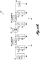
- a block diagram of a wireless power system 100 for dynamic impedance matching is shown in FIGURE 2A .
- FIGURE 2B is a block diagram illustrating an alternative system 100' wherein the drive loop 103 and the load loop 107 are functionally replaced by the ⁇ -match networks 101, 109, respectively, with the corresponding inductor L ⁇ 1, L ⁇ 2 serving at the drive and/or load loop(s).
- a first or Tx adjustable ⁇ -match network 101 is provided between an amplifier 102 and a drive loop 103 that is magnetically coupled to a high-Q MCR Tx coil 104.
- a second or Rx adjustable ⁇ -match network 109 is provided between a load loop 107 coupled to an MCR Rx coil 106 and an end device 108.
- the topology includes variable capacitors C S1 , CL1 and a fixed inductor L ⁇ 1 with the parasitic equivalent series resistance r p) on the transmit side, and variable capacitors C S2 , C L2 and a fixed inductor L ⁇ 2 on the receive side.
- the transmit side inductor L ⁇ 1 (for the first adjustable ⁇ -match network 101) and the receive side inductor L ⁇ 2 (for the second adjustable ⁇ -match network 109) may have different inductance values.
- This wireless power system 100 performs dynamic impedance matching by dynamically controlling the variable capacitances of both ⁇ -match networks 101, 109.
- Other matching networks for example L-match networks, may alternatively be used and are contemplated by the present invention.
- the ⁇ -match network is currently preferred for adaptive wireless power transfer.
- the ⁇ -match network has several advantages, for example the ⁇ -match network uses a fixed-value inductor in the high-current path, and variable capacitors that handle relatively low power in shunt configurations. Also, the ⁇ -match network is able to match source impedances that are both greater than, equal to, and less than load impedances.
- FIGURES 2A and 2B show matching networks on both the Tx side and the Rx side, it is contemplated that a system may be implemented with a matching network on only one side. It is a design consideration whether to place a matching network on both the Tx and Rx sides.
- the combination of the Tx ⁇ -match network 101 at the input to the drive loop 103 and the Rx ⁇ -match network 109 at the output from the load loop 107 provides a wider range of impedance matching between source and load impedances than would be available with either network 101, 109 alone, thus resulting in higher wireless power transfer efficiency at a single frequency for any separation distance.
- a ⁇ -match network has an extra degree of freedom from the typical L-match network, and that is the Q factor of the matching network, which can be tuned to achieve a wideband or narrowband impedance match.
- the Q factor of the matching network is fixed for a given impedance and capacitance.
- the same impedance match can be achieved for wide range of matching network Q factors.
- the current method measures one or more of the scattering parameters, or S-parameters ([S] matrices) for one or both of L ⁇ 1, L ⁇ 2 and for the set of MCR coils 104, 106, and converts the S-parameters into ABCD-matrices, as is known in the art for two-port network analysis.
- the ABCD representation is convenient because a series of cascaded two-port networks can be modeled by computing the product of their individual ABCD matrices to form a single lumped ABCD-matrix for the system.
- the ABCD matrices for the Tx ⁇ -match network 101, the MCR coils 104, 106 and the Rx ⁇ -match network 109 are multiplied together.
- the source and load capacitor values in each ⁇ -match network 101, 109 are determined by selecting values that optimize
- the method will now be described in more detail with reference to FIGURE 3 , for the system shown in FIGURE 2A .
- the [S] matrices and the [Y] matrices for the components are obtained 200.
- the S-parameters for the set of MCRs may be obtained, in a number of ways, including for example, from manufacturer data, with a vector network analyzer, with a directional coupler, or the like. It is preferable to use measured data so that all of the parasitic effects are considered. Typically, the transfer functions for a 4-coil MCR system neglect parasitic effects such as cross-coupling and coil de-tuning that can significantly reduce efficiency at the resonant frequency.
- the admittance matrices [Y] are also defined for the capacitance components of the ⁇ -match networks 101, 109. Obtaining the [S] matrices and [Y] matrices is well within the abilities of persons of skill in the art.
- the [S] and [Y] matrices are converted into [ABCD] transmission matrices 202.
- These [ABCD] matrices for the individual component are combined 204, e.g., by multiplying the cascaded [ABCD] matrices to define a system [ABCD] matrix.
- a system [S] matrix is calculated 206 from the system [ABCD] matrix using complex termination impedances to match a source impedance to a defined load impedance.
- a conventional constrained non-linear optimization algorithm may be used to determine the component values C S1 , C L1 , C S2 , C L2 in each network 208 that maximize S21. Equivalently, the algorithm may minimize the reflection S-parameter, S11. It is also contemplated that the algorithm may be configured to maximize power transfer efficiency, if data from an out of band radio is available to communicate between the power transmit side and receive side.
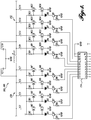
- FIGURE 4 illustrates an exemplary switching circuit that is suitable for implementing the first and/or second ⁇ -match networks 101, 109 shown in FIGURE 2A .
- the variable capacitor C S1 (or C S2 ) is implemented with a plurality of fixed capacitors C1-C7
- the variable capacitor C L1 (or C L2 ) is implemented with a plurality of fixed capacitors C9-C15, wherein the capacitors C1-C15 are networked in switchable capacitor banks 150, 152.
- Each of the capacitors C1-C15 in the capacitor banks 150, 152 are selectively engaged through a network of controllable microswitches M1-M16.
- a microcontroller 154 is configured to engage the desired capacitors, which are selected to approximately maximize S21.
- a control algorithm may exhaustively sweep each possible combination of capacitor settings while monitoring one or more of the scatter parameters, and select the configuration that achieves minimum reflected power. For example, ten switchable shunt capacitors (five on each side of the inductor) have a topology with 1,024 possible states.
- control algorithm may be configured to intelligently estimate the coupling coefficient between the two MCR coils, for example, by detecting the distance between the coils 104, 106.
- a table of the optimal component values representing the possible physical arrangements between the two MCR coils 104, 106 may be pre-calculated, and the physical positioning of the MCR coils may be used with a lookup table to control the optimal capacitor bank 150, 152 settings.
- the power delivered to the load 108 may be monitored at the receive side of the system, and an out of band radio link (not shown) may be used to report back to the control algorithm at the transmit side the status of the received power.
- the system may then automatically detect a change in distance or orientation between the MCRs 104, 106. Such changes could then be used to initiate a new sweep through the switch settings, i.e., when a change in the coupling coefficient is detected.
- the control algorithm may use a gradient approach to select only a subset of possible capacitor settings to find a local optimal transfer efficiency.
- a significant challenge in developing effective wireless power systems is the efficient rectification of RF to DC power across the systems operating points.
- This issue arises from the desire to maintain optimal impedance matching between the receiving antenna and the rectifier as the impedance of the load for the application is changing.
- an adaptive rectifier has been developed that uses a nonlinear impedance matching circuit element and control method to adapt to changes in the environment.
- FIGURE 5 A diagram of the adaptive rectifier system 120 is shown in FIGURE 5 .
- the power 122 from the Rx side second ⁇ -match network 109 ( FIGURE 2A ) is provided to a full wave rectifier 124 that converts the RF power 122 to DC power.
- a dynamic impedance matching circuit 125 is controlled by a microcontroller 126 that receives input from conventional voltage and current sensing circuits 128 and generates a pulse width modulated (PWM) control signal 127.
- PWM pulse width modulated
- the impedance matching circuit 125 uses a feed-forward buck converter 130 to control the ratio of voltage to current that is drawn from the rectifier 124 and delivered to the load 132. Additional control algorithms and/or voltage regulation stages may be provided for a particular application.
- the adaptive rectifier system 120 architecture and the control algorithms implemented on the microcontroller 126 is similar to Maximum Power Point Tracking (MPPT) techniques used for harvesting maximum power from solar cells. See, for example, U.S. Patent No. 7,986,122, to Fornage et al. , which is hereby incorporated by reference.
- MPPT Maximum Power Point Tracking
- the output of the MCR Rx coil 106 and the ⁇ -match network 109 presents a variable source resistance.
- the typical application or load 108 will also present a variable load resistance.
- the adaptive rectifier system 120 may comprise a full wave rectifier 124, over voltage protection (not shown), a high voltage synchronous NMOS driver (e.g., a high voltage synchronous N-channel MOSFET driver, such as the LTC® LTC4444 MOSFET driver available from Linear Technology Corporation, in Milpitas, Calif.), circuits for measuring voltage and current 128, and an microcontroller 126 that implements the control algorithm for tracking the maximum power point of the rectifier 124 (e.g., the MSP430TM ultra-low-power microcontroller available from Texas Instruments Incorporated, in Dallas, Texas).
- a high voltage synchronous NMOS driver e.g., a high voltage synchronous N-channel MOSFET driver, such as the LTC® LTC4444 MOSFET driver available from Linear Technology Corporation, in Milpitas, Calif.
- an microcontroller 126 that implements the control algorithm for tracking the maximum power point of the rectifier 124 (e.g., the MSP430TM ultra-low-power
- RF rectifier design One commonly overlooked aspect of RF rectifier design is that the load impedance of the application is essentially transferred through the rectifier and impacts the impedance match between the RF antenna/coils and the input of the rectifier itself. Occasionally this apparent power loss to the load is interpreted as inefficiencies in the rectifier. However, the present inventors believe RF power is being reflected off of the rectifier-antenna interface.
- the RF amplifier 102 ( FIGURE 2A ) with a source impedance of 50 ⁇ is connected to the adaptive rectifier 124.
- the RF amplifier 102 sweeps its output power from 3-30 watts at a fixed frequency of 13.56 MHz.
- an electronic load provided a second sweep of load current, which emulated different power consumption modes that an application might present.
- the resulting rectifier 124 output voltages and currents were recorded using a digital multimeter.
- a host computer running Labview® was used to control the system and record data.
- rectifier adaptive impedance matching 125 When rectifier adaptive impedance matching 125 is turned off it was observed that under some loading conditions applied to the rectifier 124 an impedance mismatch occurs between the output of the coils and the input of the rectifier 124, and this mismatch results in poor power transfer. There is only a narrow operating range where optimal power transfer can be achieved.
- the MSP430 microcontroller 126 measures the output voltage and current ratio delivered to the load 132.
- the control algorithm adjusts the PWM signal 127 that drives the feed-forward buck converter 130. This maximizes rectified power and thus maximizes the amount of power delivered to the load 132. For nearly any input power level and load current, an operating point can be found that maximizes power transfer, which resulted in a plateau of near constant transfer efficiency. The conclusion is that rectifiers that use MPPT techniques can effectively mitigate load variation, which would normally disrupt power transfer.
- the above describes a method for controlling the apparent load impedance seen by the output of the rectifier 124 to optimize the RF power transfer.
- the loading condition on the rectifier 124 maintains the optimal impedance match between the input of the rectifier 124 and the output of the RF amplifier 102.
- the maximum power point tracking algorithm on the microcontroller 126 will still servo the PWM control signal 127 to maximize the power transfer. This will in turn change the input impedance to the rectifier 124 to closely match the output impedance of the amplifier 102.
- the adaptive matching circuit block 125 can be used to control the real input impedance of the rectifier 124.
- Controlling the duty cycle of the feed-forward buck converter 130 allows the adaptive rectifier to servo its input impedance.
- some reactance is introduced and the impedance matching is not purely real. This is believed to be due to the junction capacitance of the diodes.
- One possible improvement to the system therefore, would be to mitigate this parasitic reactance with a switched impedance matching network.
- this shows that using a feed-forward buck converter 130 to form an adaptive rectifier is an effective means of electronically controlling the RF impedance of a rectifier 124 using only solid state devices.
- FIGURE 6 Another embodiment of a system 140 for adaptive wireless power transfer using MCRs shown in FIGURE 6 , which includes the MCR system shown in FIGURE 2A , with ⁇ -match networks 101, 109 on both the Tx side and the Rx side.
- the system 140 includes a transmitter board 142 with a digital signal processor (DSP) 144 (e.g., a TMS320® DSP available from Texas Instruments Incorporated).
- DSP digital signal processor
- the DSP 144 controls all peripherals on the transmitter board 142 and communicates with an external PC via a serial-to-USB chip (not shown).
- the incident and reflected ports of a directional coupler 146 are attached to the inputs of an RF detector chip 148.
- the detector chip 148 outputs a voltage that is proportional to the log magnitude ratio and phase between incident and reflected power (i.e., 1/S11). For example, if the DSP 144 is clocked at 150 MHz it may take many digital samples in a short period of time. In fact, it only takes this system 140 about 5 ⁇ s to take one data point.
- the DSP 144 uses these measurements to adjust the transmit frequency of an RF synthesizer 151, which drives the amplifier 102 through a low-pass filter 153.
- the system 140 may also employ dynamic impedance matching by controlling ⁇ -match boards 101, 109, for example, via parallel general purpose input/output ("GPIO") interfaces from the DSP 144.
- An external RF amplifier 102 is used to achieve an output power of up to 100W in this exemplary embodiment.
- the receive side includes a receiver board 160 that may incorporate the rectifier system 120 shown in FIGURE 5 .
- both the transmitter board 142 and the receiver board 160 include out-of-band radios 149, 169 (e.g., CC2500 transceivers available from Texas Instruments Incorporated), which implement out-of-band communication and allow the load to provide information about power consumption, position, or orientation, as well as control for a remote ⁇ -match board.
- out-of-band radios 149, 169 e.g., CC2500 transceivers available from Texas Instruments Incorporated
- the system's 140 control algorithm chooses the optimal system parameters ( ⁇ -match settings) given the current system state and maximizes power transfer over time as described above.
- the system 140 is capable of fixed frequency operation using dynamic impedance matching.
- ⁇ -match boards 101, 109 contain capacitor banks that can be switched on or off by a parallel GPIO interface.
- the search space for actively controlling the ⁇ -match networks 101, 109 is more complicated than that of frequency tuning. Where frequency tuning's search space was one-dimensional, the space for impedance matching is two-dimensional, as the system can change both the Tx-side or Rx-side capacitances.
- the bank capacitor values should be chosen to provide the most effective matching circuit with the fewest number of capacitors. It is contemplated that for any given arrangement of MRC coils 104, 106 it may be determined that some capacitor settings will not correspond to optimal impedance matches, and may be excluded from the search space ahead of time.
- Wireless power systems based on magnetically coupled resonators can realize the vision of seamless, reliable wireless power delivery if they are able to adapt to variations in range, orientation, and loading conditions.
- the key insight is that the over-coupled regime allows for high efficiency and near constant power delivery if the system is tuned properly.
- adaptive impedance matching techniques used for fixed frequency operation can enable wireless power delivery to larger areas of space than previously published work.
- an adaptive rectifier topology that is capable of adapting to changes in loading conditions to allow for optimal power delivery to the load.
- the adaptive rectification technique also allows a receiver to control its input impedance to ensure proper matching to the magnetically coupled resonators.
- a full end-to-end system capable of adapting to real-time changes in the environment while maintaining optimum efficiency is disclosed.
Landscapes
- Health & Medical Sciences (AREA)
- Engineering & Computer Science (AREA)
- Heart & Thoracic Surgery (AREA)
- Cardiology (AREA)
- Biomedical Technology (AREA)
- Veterinary Medicine (AREA)
- Mechanical Engineering (AREA)
- Anesthesiology (AREA)
- Public Health (AREA)
- Hematology (AREA)
- Life Sciences & Earth Sciences (AREA)
- Animal Behavior & Ethology (AREA)
- General Health & Medical Sciences (AREA)
- Computer Networks & Wireless Communication (AREA)
- Power Engineering (AREA)
- Medical Informatics (AREA)
- Charge And Discharge Circuits For Batteries Or The Like (AREA)
- Electrotherapy Devices (AREA)
- Near-Field Transmission Systems (AREA)
Applications Claiming Priority (6)
| Application Number | Priority Date | Filing Date | Title |
|---|---|---|---|
| US201261649496P | 2012-05-21 | 2012-05-21 | |
| US201261691127P | 2012-08-20 | 2012-08-20 | |
| US201261734236P | 2012-12-06 | 2012-12-06 | |
| US13/843,884 US8827889B2 (en) | 2012-05-21 | 2013-03-15 | Method and system for powering implantable devices |
| PCT/US2013/042085 WO2013177205A1 (en) | 2012-05-21 | 2013-05-21 | Wireless power delivery in dynamic environments |
| EP13793259.6A EP2853016B1 (de) | 2012-05-21 | 2013-05-21 | Drahtlose stromversorgung in dynamischen umgebungen |
Related Parent Applications (2)
| Application Number | Title | Priority Date | Filing Date |
|---|---|---|---|
| EP13793259.6A Division EP2853016B1 (de) | 2012-05-21 | 2013-05-21 | Drahtlose stromversorgung in dynamischen umgebungen |
| EP13793259.6A Division-Into EP2853016B1 (de) | 2012-05-21 | 2013-05-21 | Drahtlose stromversorgung in dynamischen umgebungen |
Publications (2)
| Publication Number | Publication Date |
|---|---|
| EP3236558A1 true EP3236558A1 (de) | 2017-10-25 |
| EP3236558B1 EP3236558B1 (de) | 2018-12-19 |
Family
ID=49581863
Family Applications (2)
| Application Number | Title | Priority Date | Filing Date |
|---|---|---|---|
| EP13793259.6A Active EP2853016B1 (de) | 2012-05-21 | 2013-05-21 | Drahtlose stromversorgung in dynamischen umgebungen |
| EP17173137.5A Active EP3236558B1 (de) | 2012-05-21 | 2013-05-21 | Drahtlose stromversorgung in dynamischen umgebungen |
Family Applications Before (1)
| Application Number | Title | Priority Date | Filing Date |
|---|---|---|---|
| EP13793259.6A Active EP2853016B1 (de) | 2012-05-21 | 2013-05-21 | Drahtlose stromversorgung in dynamischen umgebungen |
Country Status (3)
| Country | Link |
|---|---|
| US (4) | US8827889B2 (de) |
| EP (2) | EP2853016B1 (de) |
| WO (1) | WO2013177205A1 (de) |
Cited By (1)
| Publication number | Priority date | Publication date | Assignee | Title |
|---|---|---|---|---|
| KR20200064420A (ko) * | 2018-11-29 | 2020-06-08 | 한국과학기술원 | 다중 장치 무선전력전송 시스템에 대한 자기공진조건 탐색방법 |
Families Citing this family (80)
| Publication number | Priority date | Publication date | Assignee | Title |
|---|---|---|---|---|
| US8827889B2 (en) | 2012-05-21 | 2014-09-09 | University Of Washington Through Its Center For Commercialization | Method and system for powering implantable devices |
| US11621583B2 (en) | 2012-05-21 | 2023-04-04 | University Of Washington | Distributed control adaptive wireless power transfer system |
| US10383990B2 (en) | 2012-07-27 | 2019-08-20 | Tc1 Llc | Variable capacitor for resonant power transfer systems |
| US9592397B2 (en) | 2012-07-27 | 2017-03-14 | Thoratec Corporation | Thermal management for implantable wireless power transfer systems |
| WO2014018971A1 (en) | 2012-07-27 | 2014-01-30 | Thoratec Corporation | Resonant power transfer systems with protective algorithm |
| US9805863B2 (en) | 2012-07-27 | 2017-10-31 | Thoratec Corporation | Magnetic power transmission utilizing phased transmitter coil arrays and phased receiver coil arrays |
| WO2014018973A1 (en) | 2012-07-27 | 2014-01-30 | Thoratec Corporation | Resonant power transmission coils and systems |
| WO2014018967A1 (en) | 2012-07-27 | 2014-01-30 | Thoratec Corporation | Self-tuning resonant power transfer systems |
| US10525181B2 (en) | 2012-07-27 | 2020-01-07 | Tc1 Llc | Resonant power transfer system and method of estimating system state |
| US10291067B2 (en) | 2012-07-27 | 2019-05-14 | Tc1 Llc | Computer modeling for resonant power transfer systems |
| US9789236B2 (en) | 2013-03-14 | 2017-10-17 | Yale University | Implantable heart pump controller |
| WO2014145664A1 (en) | 2013-03-15 | 2014-09-18 | Thoratec Corporation | Integrated implantable tets housing including fins and coil loops |
| US10373756B2 (en) | 2013-03-15 | 2019-08-06 | Tc1 Llc | Malleable TETs coil with improved anatomical fit |
| WO2015061780A1 (en) | 2013-10-25 | 2015-04-30 | Greene Charles E | Bi-stable display tag |
| KR20150050024A (ko) * | 2013-10-31 | 2015-05-08 | 삼성전기주식회사 | 무선 전력 중계 장치 및 이를 구비하는 케이스 |
| EP3069358B1 (de) | 2013-11-11 | 2019-06-12 | Tc1 Llc | Resonante stromübertragungsspule mit einem scharnier |
| WO2015070200A1 (en) | 2013-11-11 | 2015-05-14 | Thoratec Corporation | Resonant power transfer systems with communications |
| EP3072210B1 (de) * | 2013-11-11 | 2023-12-20 | Tc1 Llc | Resonante stromübertragungssysteme mit kommunikation |
| WO2015084587A1 (en) | 2013-12-03 | 2015-06-11 | Massachusetts Institute Of Technology | Method and apparatus for wirelessly charging portable electronic devices |
| US9724525B2 (en) | 2014-01-30 | 2017-08-08 | Cochlear Limited | Power and data transfer in hearing prostheses |
| WO2015119511A1 (en) | 2014-02-07 | 2015-08-13 | Powerbyproxi Limited | Inductive power receiver with resonant coupling regulator |
| US9780597B2 (en) | 2014-02-27 | 2017-10-03 | GM Global Technology Operations LLC | Vehicular electrical architecture of both wireless power and communication peripherals using MRC |
| WO2015134871A1 (en) | 2014-03-06 | 2015-09-11 | Thoratec Corporation | Electrical connectors for implantable devices |
| CA2945711A1 (en) * | 2014-04-15 | 2015-10-22 | Heartware, Inc. | Improvements in transcutaneous energy transfer systems |
| EP3248650B1 (de) | 2014-04-15 | 2018-12-05 | Heartware, Inc. | Verbesserungen an transkutanen energieübertragungssystemen |
| US10293090B2 (en) | 2014-04-25 | 2019-05-21 | Yale University | Percutaneous device and method for promoting movement of a bodily fluid |
| WO2015200436A1 (en) * | 2014-06-24 | 2015-12-30 | Board Of Trustees Of The University Of Alabama | Wireless power transfer systems and methods |
| AU2015296236A1 (en) * | 2014-07-30 | 2017-03-09 | University Of Washington | Adaptive and multi-transmitter wireless power for robots |
| US10512553B2 (en) | 2014-07-30 | 2019-12-24 | The Alfred E. Mann Foundation For Scientific Research | Inductive link coil de-tuning compensation and control |
| US10123096B2 (en) * | 2014-08-05 | 2018-11-06 | Minipumps, Llc | Implant telemetry with dynamic tuning |
| JP2017522992A (ja) * | 2014-08-05 | 2017-08-17 | ミニパンプス, エルエルシー | 動的な同調を用いる埋込物テレメトリ |
| EP3826104B1 (de) | 2014-09-22 | 2023-05-03 | Tc1 Llc | Antennenentwürfe zur kommunikation zwischen einem drahtlos betriebenen implantat mit einer externen vorrichtung ausserhalb des körpers |
| EP3204989B1 (de) | 2014-10-06 | 2019-08-21 | Tc1 Llc | Mehrachsiger steckverbinder für implantierbare vorrichtungen |
| US9750923B2 (en) | 2014-11-19 | 2017-09-05 | Velóce Corporation | Wireless communications system integrating electronics into orally ingestible products for controlled release of active ingredients |
| US10729834B2 (en) | 2014-12-19 | 2020-08-04 | Yale University | Heart failure recovery device and method of treatment |
| KR102363641B1 (ko) * | 2015-01-14 | 2022-02-17 | 삼성전자주식회사 | 웨어러블 기기 |
| CA2975508C (en) * | 2015-02-04 | 2022-11-29 | The Alfred E. Mann Foundation For Scientific Research | Inductive link coil de-tuning compensation and control |
| CN104682580B (zh) * | 2015-03-24 | 2016-11-02 | 哈尔滨工业大学 | 基于多级复合谐振结构并联的电动汽车动态无线供电系统及采用该系统实现的供电方法 |
| CN108337919B (zh) * | 2015-06-01 | 2021-10-29 | 香港大学 | 用于标识无线充电系统中的线圈未对准/互耦的快速方法 |
| CN104941017B (zh) * | 2015-07-10 | 2017-10-10 | 北京工业大学 | 为人工心脏提供电源的能量无线定向传递系统 |
| US10498160B2 (en) | 2015-08-03 | 2019-12-03 | Massachusetts Institute Of Technology | Efficiency maximization for device-to-device wireless charging |
| US10148126B2 (en) | 2015-08-31 | 2018-12-04 | Tc1 Llc | Wireless energy transfer system and wearables |
| EP3902100A1 (de) | 2015-10-07 | 2021-10-27 | Tc1 Llc | Resonante leistungsübertragungssysteme mit effizienzoptimierung basierend auf empfängerimpedanz |
| EP3364870B1 (de) * | 2015-10-21 | 2022-09-07 | Neuspera Medical Inc. | Vorrichtungen und systeme zur stimulationstherapie |
| WO2017132374A1 (en) * | 2016-01-29 | 2017-08-03 | Axonics Modulation Technologies, Inc. | Methods and systems for frequency adjustment to optimize charging of implantable neurostimulator |
| WO2017139406A1 (en) | 2016-02-08 | 2017-08-17 | Witricity Corporation | Pwm capacitor control |
| CN108697897B (zh) | 2016-02-12 | 2023-01-13 | 艾克索尼克斯股份有限公司 | 用于试验神经刺激的外部脉冲发生器设备和相关联方法 |
| US10618651B2 (en) | 2016-02-22 | 2020-04-14 | WiBotic Inc. | Systems and methods of electrically powering devices |
| JP6688638B2 (ja) * | 2016-03-10 | 2020-04-28 | キヤノンメディカルシステムズ株式会社 | 磁気共鳴イメージング装置 |
| US10898292B2 (en) | 2016-09-21 | 2021-01-26 | Tc1 Llc | Systems and methods for locating implanted wireless power transmission devices |
| US10250078B2 (en) * | 2016-10-18 | 2019-04-02 | Robert A Moffatt | Wireless power transfer to multiple receiver devices across a variable-sized area |
| WO2018136592A2 (en) | 2017-01-18 | 2018-07-26 | Tc1 Llc | Systems and methods for transcutaneous power transfer using microneedles |
| US10686336B2 (en) * | 2017-05-30 | 2020-06-16 | Wireless Advanced Vehicle Electrification, Inc. | Single feed multi-pad wireless charging |
| US11707996B2 (en) | 2017-12-15 | 2023-07-25 | WiBotic Inc. | Wireless charging with multiple charging locations |
| US11701976B2 (en) | 2017-12-15 | 2023-07-18 | WiBotic Inc. | Device authentication for wireless charging |
| WO2019135890A1 (en) | 2018-01-04 | 2019-07-11 | Tc1 Llc | Systems and methods for elastic wireless power transmission devices |
| CN108092419B (zh) * | 2018-01-22 | 2023-10-20 | 天津中德应用技术大学 | 基于电磁耦合无线传能的教学装置 |
| US10651687B2 (en) | 2018-02-08 | 2020-05-12 | Massachusetts Institute Of Technology | Detuning for a resonant wireless power transfer system including cryptography |
| US11018526B2 (en) | 2018-02-08 | 2021-05-25 | Massachusetts Institute Of Technology | Detuning for a resonant wireless power transfer system including cooperative power sharing |
| US12491356B2 (en) | 2018-03-20 | 2025-12-09 | Second Heart Assist, Inc. | Circulatory assist pump |
| US12364855B2 (en) * | 2018-06-13 | 2025-07-22 | Yale University | Intracardiac device |
| CN109286235B (zh) * | 2018-11-27 | 2023-08-22 | 南方电网科学研究院有限责任公司 | 一种电力系统监测设备的供电系统 |
| US11642537B2 (en) | 2019-03-11 | 2023-05-09 | Axonics, Inc. | Charging device with off-center coil |
| EP3726702B1 (de) * | 2019-04-17 | 2021-11-03 | EM Microelectronic-Marin SA | Verfahren und system zur leistungsübertragung eines signals vom typ funkfrequenz, das von einem funkfrequenzempfänger empfangen wird |
| US11844925B2 (en) | 2019-06-06 | 2023-12-19 | Medtronic Minimed, Inc. | Fluid infusion systems |
| CN110393830A (zh) * | 2019-09-05 | 2019-11-01 | 长治市人工心脏研发中心 | 一种基于磁共振技术的人工心脏无线供电系统 |
| US11757307B2 (en) * | 2020-01-03 | 2023-09-12 | Nucurrent, Inc. | Systems and methods for dynamically tuning a wireless power transfer system |
| JP7713951B2 (ja) | 2020-03-10 | 2025-07-28 | ティーシー1 エルエルシー | 心室補助装置に無線電力伝送するシステム及び方法 |
| EP4138987A4 (de) | 2020-04-22 | 2024-09-04 | The Regents of the University of California | Vorrichtung und verfahren zur echtzeit-resonanzanpassung für leistungsempfänger |
| CN113852173B (zh) | 2020-06-28 | 2026-02-10 | 伏达半导体(合肥)股份有限公司 | 用于无线电力传输系统的瞬态保护设备和方法 |
| CN111835092B (zh) * | 2020-07-27 | 2021-05-18 | 北京理工大学 | 一种无线充电系统的双边lcc补偿网络调节方法及系统 |
| US12352608B2 (en) * | 2020-08-22 | 2025-07-08 | The Regents Of The University Of California | Augmented telemetry using coupled magnetic resonances |
| US12036416B2 (en) | 2020-11-09 | 2024-07-16 | West Affum Holdings Dac | Wearable cardioverter defibrillator (WCD) system with wireless battery charging |
| EP4327579A1 (de) | 2021-04-21 | 2024-02-28 | T.J. Smith and Nephew, Limited | Kommunikationssysteme und verfahren für unterdruckwundtherapievorrichtungen |
| US20230075608A1 (en) * | 2021-09-09 | 2023-03-09 | Second Heart Assist, Inc. | Circulatory assist pumps, abdominal belts for charging circulatory assist pumps, deployment catheters, retrieval catheters, and related systems and methods |
| US11799321B1 (en) | 2022-08-18 | 2023-10-24 | Avago Technologies International Sales Pte. Limited | Impedance matching for wirelss power transfer |
| US11726152B1 (en) * | 2022-08-26 | 2023-08-15 | Jeol Ltd. | Solid sample magnetic coupling high resolution nuclear magnetic resolution probe and method of use |
| CN116231884B (zh) * | 2022-09-06 | 2023-10-20 | 荣耀终端有限公司 | 一种电力接收装置、电力发送装置及电力传输方法 |
| US20240165395A1 (en) * | 2022-11-18 | 2024-05-23 | Corisma Cardiovascular | Transmitting and receiving antennas for transferring power to implanted medical devices |
| CN119345600B (zh) * | 2024-10-23 | 2025-08-19 | 广州市爱因电子有限公司 | 一种空间电场发生系统 |
Citations (8)
| Publication number | Priority date | Publication date | Assignee | Title |
|---|---|---|---|---|
| WO2010108191A1 (en) * | 2009-03-20 | 2010-09-23 | Qualcomm Incorporated | Adaptive impedance tuning in wireless power transmission |
| US20110053500A1 (en) * | 2009-09-02 | 2011-03-03 | Qualcomm Incorporated | De-tuning in wireless power reception |
| US20110169337A1 (en) * | 2010-01-08 | 2011-07-14 | Sony Corporation | Power feed device, power receiving device, and wireless power feed system |
| US7986122B2 (en) | 2007-09-26 | 2011-07-26 | Enphase Energy, Inc. | Method and apparatus for power conversion with maximum power point tracking and burst mode capability |
| US20120049648A1 (en) * | 2010-08-31 | 2012-03-01 | Jin Sung Choi | Adaptive resonance power transmitter |
| US20120080957A1 (en) | 2008-08-20 | 2012-04-05 | Cooper Emily B | Wireless power transfer apparatus and method thereof |
| US20120153738A1 (en) | 2008-09-27 | 2012-06-21 | Aristeidis Karalis | Wireless energy transfer across variable distances using field shaping with magnetic materials to improve the coupling factor |
| US20120161536A1 (en) * | 2010-12-24 | 2012-06-28 | Semiconductor Energy Laboratory Co., Ltd. | Wireless power feeding system |
Family Cites Families (84)
| Publication number | Priority date | Publication date | Assignee | Title |
|---|---|---|---|---|
| US3553736A (en) | 1968-11-25 | 1971-01-12 | Us Health Education & Welfare | Auxiliary ventricle |
| US4809681A (en) | 1986-03-28 | 1989-03-07 | Aisin Seiki Kabushiki Kaisha | Electrocardiographic measurement method for controlling an intra-aortic balloon pump |
| US5290227A (en) | 1992-08-06 | 1994-03-01 | Pasque Michael K | Method of implanting blood pump in ascending aorta or main pulmonary artery |
| US5630836A (en) * | 1995-01-19 | 1997-05-20 | Vascor, Inc. | Transcutaneous energy and information transmission apparatus |
| US5980448A (en) | 1998-01-28 | 1999-11-09 | Vascor, Inc. | Single chamber blood pump |
| US6331744B1 (en) * | 1998-02-10 | 2001-12-18 | Light Sciences Corporation | Contactless energy transfer apparatus |
| US6445956B1 (en) | 1999-10-18 | 2002-09-03 | Abiomed, Inc. | Implantable medical device |
| JP4207336B2 (ja) | 1999-10-29 | 2009-01-14 | ソニー株式会社 | 移動ロボットのための充電システム、充電ステーションを探索する方法、移動ロボット、コネクタ、及び、電気的接続構造 |
| US7616997B2 (en) | 2000-09-27 | 2009-11-10 | Kieval Robert S | Devices and methods for cardiovascular reflex control via coupled electrodes |
| US6632169B2 (en) | 2001-03-13 | 2003-10-14 | Ltk Enterprises, L.L.C. | Optimized pulsatile-flow ventricular-assist device and total artificial heart |
| US6894456B2 (en) | 2001-11-07 | 2005-05-17 | Quallion Llc | Implantable medical power module |
| US6669624B2 (en) | 2002-03-26 | 2003-12-30 | O. Howard Frazier | Temporary heart-assist system |
| AU2002951685A0 (en) | 2002-09-30 | 2002-10-17 | Ventrassist Pty Ltd | Physiological demand responsive control system |
| CA2506758C (en) | 2002-12-06 | 2014-03-11 | World Heart Corporation | Miniature, pulsatile implantable ventricular assist devices and methods of controlling ventricular assist devices |
| US7269460B2 (en) | 2003-02-28 | 2007-09-11 | Medtronic, Inc. | Method and apparatus for evaluating and optimizing ventricular synchronization |
| US20050085683A1 (en) | 2003-10-15 | 2005-04-21 | Bolling Steven F. | Implantable heart assist system and method of applying same |
| ES2561354T3 (es) | 2003-10-31 | 2016-02-25 | Sunshine Heart Company Pty Ltd | Sistema de control de sincronización |
| LT1715902T (lt) | 2004-01-08 | 2016-11-10 | Sullivan, Paul Joseph | Neišardomas fluido perdavimo įrenginys |
| KR101118710B1 (ko) | 2005-07-12 | 2012-03-13 | 메사추세츠 인스티튜트 오브 테크놀로지 | 무선 비-방사성 에너지 전달 |
| US7825543B2 (en) | 2005-07-12 | 2010-11-02 | Massachusetts Institute Of Technology | Wireless energy transfer |
| KR100684794B1 (ko) * | 2005-08-11 | 2007-02-20 | 삼성에스디아이 주식회사 | 플라즈마 표시 장치 및 게이트 구동 장치 |
| US7714676B2 (en) | 2006-11-08 | 2010-05-11 | Paratek Microwave, Inc. | Adaptive impedance matching apparatus, system and method |
| US20080143192A1 (en) | 2006-12-14 | 2008-06-19 | Sample Alanson P | Dynamic radio frequency power harvesting |
| US9774086B2 (en) * | 2007-03-02 | 2017-09-26 | Qualcomm Incorporated | Wireless power apparatus and methods |
| KR101356409B1 (ko) | 2007-03-27 | 2014-01-27 | 메사추세츠 인스티튜트 오브 테크놀로지 | 무선 에너지 전달 |
| US7741881B2 (en) * | 2007-03-30 | 2010-06-22 | Intel Corporation | MOSFET gate interface |
| US8095085B2 (en) * | 2007-06-08 | 2012-01-10 | Arizona Board Of Regents For And On Behalf Of Arizona State University | Automatic antenna tuning unit for software-defined and cognitive radio |
| WO2009019020A1 (de) | 2007-08-08 | 2009-02-12 | Fraunhofer-Gesellschaft zur Förderung der angewandten Forschung e.V. | Laserschutzwandelelement für eine umhausung bei laserbearbeitungsanlagen |
| US8766483B2 (en) * | 2007-11-28 | 2014-07-01 | Qualcomm Incorporated | Wireless power range increase using parasitic antennas |
| WO2009140506A1 (en) | 2008-05-14 | 2009-11-19 | Massachusetts Institute Of Technology | Wireless energy transfer, including interference enhancement |
| US20100016937A1 (en) | 2008-07-18 | 2010-01-21 | Yousef Alkhatib | Twisting Bifurcation Delivery System |
| US8374700B2 (en) | 2008-07-31 | 2013-02-12 | Medtronic, Inc. | Adjustable impedance matching circuit |
| US7893564B2 (en) | 2008-08-05 | 2011-02-22 | Broadcom Corporation | Phased array wireless resonant power delivery system |
| US8299652B2 (en) | 2008-08-20 | 2012-10-30 | Intel Corporation | Wireless power transfer apparatus and method thereof |
| US20100081379A1 (en) | 2008-08-20 | 2010-04-01 | Intel Corporation | Wirelessly powered speaker |
| US20100045114A1 (en) * | 2008-08-20 | 2010-02-25 | Sample Alanson P | Adaptive wireless power transfer apparatus and method thereof |
| CN102149425B (zh) * | 2008-09-10 | 2014-11-05 | 海德威公司 | 用于植入医疗设备的tet系统 |
| US8497601B2 (en) | 2008-09-27 | 2013-07-30 | Witricity Corporation | Wireless energy transfer converters |
| US9601261B2 (en) | 2008-09-27 | 2017-03-21 | Witricity Corporation | Wireless energy transfer using repeater resonators |
| US8587155B2 (en) | 2008-09-27 | 2013-11-19 | Witricity Corporation | Wireless energy transfer using repeater resonators |
| US9184595B2 (en) | 2008-09-27 | 2015-11-10 | Witricity Corporation | Wireless energy transfer in lossy environments |
| WO2010036980A1 (en) | 2008-09-27 | 2010-04-01 | Witricity Corporation | Wireless energy transfer systems |
| US8772973B2 (en) | 2008-09-27 | 2014-07-08 | Witricity Corporation | Integrated resonator-shield structures |
| US8461721B2 (en) | 2008-09-27 | 2013-06-11 | Witricity Corporation | Wireless energy transfer using object positioning for low loss |
| US8723366B2 (en) | 2008-09-27 | 2014-05-13 | Witricity Corporation | Wireless energy transfer resonator enclosures |
| US20100259110A1 (en) | 2008-09-27 | 2010-10-14 | Kurs Andre B | Resonator optimizations for wireless energy transfer |
| US8552592B2 (en) | 2008-09-27 | 2013-10-08 | Witricity Corporation | Wireless energy transfer with feedback control for lighting applications |
| US20110043049A1 (en) | 2008-09-27 | 2011-02-24 | Aristeidis Karalis | Wireless energy transfer with high-q resonators using field shaping to improve k |
| US8461720B2 (en) | 2008-09-27 | 2013-06-11 | Witricity Corporation | Wireless energy transfer using conducting surfaces to shape fields and reduce loss |
| US8947186B2 (en) | 2008-09-27 | 2015-02-03 | Witricity Corporation | Wireless energy transfer resonator thermal management |
| US20120248888A1 (en) | 2008-09-27 | 2012-10-04 | Kesler Morris P | Wireless energy transfer with resonator arrays for medical applications |
| US8304935B2 (en) | 2008-09-27 | 2012-11-06 | Witricity Corporation | Wireless energy transfer using field shaping to reduce loss |
| US8324759B2 (en) | 2008-09-27 | 2012-12-04 | Witricity Corporation | Wireless energy transfer using magnetic materials to shape field and reduce loss |
| US8692410B2 (en) | 2008-09-27 | 2014-04-08 | Witricity Corporation | Wireless energy transfer with frequency hopping |
| US8598743B2 (en) | 2008-09-27 | 2013-12-03 | Witricity Corporation | Resonator arrays for wireless energy transfer |
| US8692412B2 (en) | 2008-09-27 | 2014-04-08 | Witricity Corporation | Temperature compensation in a wireless transfer system |
| US20100277121A1 (en) | 2008-09-27 | 2010-11-04 | Hall Katherine L | Wireless energy transfer between a source and a vehicle |
| US20110074346A1 (en) | 2009-09-25 | 2011-03-31 | Hall Katherine L | Vehicle charger safety system and method |
| US8482158B2 (en) | 2008-09-27 | 2013-07-09 | Witricity Corporation | Wireless energy transfer using variable size resonators and system monitoring |
| US8643326B2 (en) | 2008-09-27 | 2014-02-04 | Witricity Corporation | Tunable wireless energy transfer systems |
| EP2345100B1 (de) | 2008-10-01 | 2018-12-05 | Massachusetts Institute of Technology | Effiziente nahfeld-drahtlosenergieübertragung anhand adiabatischer systemveränderungen |
| AU2009302931B2 (en) * | 2008-10-10 | 2015-10-29 | Medicaltree Patent Ltd | Heart help pump, system, and method |
| KR101248453B1 (ko) * | 2008-12-09 | 2013-04-01 | 도요타지도샤가부시키가이샤 | 비접촉 전력 전송 장치 및 비접촉 전력 전송 장치에 있어서의 전력 전송 방법 |
| DE102009024747A1 (de) * | 2009-01-22 | 2010-07-29 | Epcos Ag | Adaptive Impedanzanpassschaltung und Verfahren zur Anpassung für Duplexbetrieb-Standards |
| US8497658B2 (en) | 2009-01-22 | 2013-07-30 | Qualcomm Incorporated | Adaptive power control for wireless charging of devices |
| US8866561B2 (en) | 2009-02-17 | 2014-10-21 | Qualcomm Technologies, Inc. | Adaptive impedance matching network |
| US8143746B2 (en) | 2009-12-21 | 2012-03-27 | Alcatel Lucent | Automatic tuning for wireless power transfer |
| US8562508B2 (en) | 2009-12-30 | 2013-10-22 | Thoratec Corporation | Mobility-enhancing blood pump system |
| EP2525870B1 (de) | 2010-01-19 | 2019-03-13 | Heartware, Inc. | Physiologisch reagierendes ventrikuläres unterstützungssystem |
| CN102947124B (zh) | 2010-05-19 | 2017-02-08 | 高通股份有限公司 | 自适应无线能量传送系统 |
| USD636333S1 (en) | 2010-09-23 | 2011-04-19 | Witricity Corporation | Wireless power source |
| US8618766B2 (en) | 2010-09-27 | 2013-12-31 | Deere & Company | Robot power source charging station |
| US8901775B2 (en) | 2010-12-10 | 2014-12-02 | Everheart Systems, Inc. | Implantable wireless power system |
| US9178369B2 (en) | 2011-01-18 | 2015-11-03 | Mojo Mobility, Inc. | Systems and methods for providing positioning freedom, and support of different voltages, protocols, and power levels in a wireless power system |
| KR20120097239A (ko) * | 2011-02-24 | 2012-09-03 | 삼성전기주식회사 | 무선 전력 전송 시스템 |
| US8938026B2 (en) | 2011-03-22 | 2015-01-20 | Intel IP Corporation | System and method for tuning an antenna in a wireless communication device |
| US8767871B2 (en) | 2011-06-08 | 2014-07-01 | Broadcom Corporation | Antenna tuning using the ratio of complex forward and reflected signals |
| US20150280444A1 (en) | 2012-05-21 | 2015-10-01 | University Of Washington Through Its Center For Commercialization | Wireless power delivery in dynamic environments |
| US8827889B2 (en) | 2012-05-21 | 2014-09-09 | University Of Washington Through Its Center For Commercialization | Method and system for powering implantable devices |
| US9859755B2 (en) | 2012-07-16 | 2018-01-02 | Qualcomm Incorporated | Device alignment and identification in inductive power transfer systems |
| US9666357B2 (en) | 2012-09-11 | 2017-05-30 | Qualcomm Incorporated | Apparatus system, and method for wirelessly receiving power using conductive structures |
| US9919088B2 (en) | 2013-03-14 | 2018-03-20 | Yale University | Implantable heart pump controller |
| AU2015296236A1 (en) | 2014-07-30 | 2017-03-09 | University Of Washington | Adaptive and multi-transmitter wireless power for robots |
| KR102236287B1 (ko) * | 2016-12-01 | 2021-04-07 | 이피션트 파워 컨버젼 코퍼레이션 | GaN 트랜지스터 기반 파워 컨버터를 위한 부트스트랩 커패시터 과전압 관리 회로 |
-
2013
- 2013-03-15 US US13/843,884 patent/US8827889B2/en not_active Expired - Fee Related
- 2013-05-21 EP EP13793259.6A patent/EP2853016B1/de active Active
- 2013-05-21 WO PCT/US2013/042085 patent/WO2013177205A1/en not_active Ceased
- 2013-05-21 EP EP17173137.5A patent/EP3236558B1/de active Active
-
2014
- 2014-09-09 US US14/481,569 patent/US9415149B2/en not_active Expired - Fee Related
-
2019
- 2019-03-19 US US16/358,528 patent/US11090481B2/en active Active
-
2021
- 2021-07-15 US US17/376,861 patent/US11722017B2/en active Active
Patent Citations (8)
| Publication number | Priority date | Publication date | Assignee | Title |
|---|---|---|---|---|
| US7986122B2 (en) | 2007-09-26 | 2011-07-26 | Enphase Energy, Inc. | Method and apparatus for power conversion with maximum power point tracking and burst mode capability |
| US20120080957A1 (en) | 2008-08-20 | 2012-04-05 | Cooper Emily B | Wireless power transfer apparatus and method thereof |
| US20120153738A1 (en) | 2008-09-27 | 2012-06-21 | Aristeidis Karalis | Wireless energy transfer across variable distances using field shaping with magnetic materials to improve the coupling factor |
| WO2010108191A1 (en) * | 2009-03-20 | 2010-09-23 | Qualcomm Incorporated | Adaptive impedance tuning in wireless power transmission |
| US20110053500A1 (en) * | 2009-09-02 | 2011-03-03 | Qualcomm Incorporated | De-tuning in wireless power reception |
| US20110169337A1 (en) * | 2010-01-08 | 2011-07-14 | Sony Corporation | Power feed device, power receiving device, and wireless power feed system |
| US20120049648A1 (en) * | 2010-08-31 | 2012-03-01 | Jin Sung Choi | Adaptive resonance power transmitter |
| US20120161536A1 (en) * | 2010-12-24 | 2012-06-28 | Semiconductor Energy Laboratory Co., Ltd. | Wireless power feeding system |
Non-Patent Citations (1)
| Title |
|---|
| A. SAMPLE; D. MEYER; J. SMITH: "Analysis, Experimental results, and range adaptation of magnetically coupled resonators for wireless power transfer", INDUSTRIAL ELECTRONICS, IEEE TRANSACTIONS ON, vol. 58, no. 2, February 2011 (2011-02-01), pages 544 - 554, XP011354363, DOI: doi:10.1109/TIE.2010.2046002 |
Cited By (1)
| Publication number | Priority date | Publication date | Assignee | Title |
|---|---|---|---|---|
| KR20200064420A (ko) * | 2018-11-29 | 2020-06-08 | 한국과학기술원 | 다중 장치 무선전력전송 시스템에 대한 자기공진조건 탐색방법 |
Also Published As
| Publication number | Publication date |
|---|---|
| US9415149B2 (en) | 2016-08-16 |
| EP3236558B1 (de) | 2018-12-19 |
| US20190280527A1 (en) | 2019-09-12 |
| US11722017B2 (en) | 2023-08-08 |
| US20140378743A1 (en) | 2014-12-25 |
| EP2853016A4 (de) | 2016-01-27 |
| EP2853016A1 (de) | 2015-04-01 |
| US20130310630A1 (en) | 2013-11-21 |
| WO2013177205A1 (en) | 2013-11-28 |
| US8827889B2 (en) | 2014-09-09 |
| US11090481B2 (en) | 2021-08-17 |
| EP2853016B1 (de) | 2017-07-05 |
| US20210339008A1 (en) | 2021-11-04 |
Similar Documents
| Publication | Publication Date | Title |
|---|---|---|
| US11722017B2 (en) | Wireless power delivery in dynamic environments | |
| US20150280444A1 (en) | Wireless power delivery in dynamic environments | |
| Waters et al. | Adaptive impedance matching for magnetically coupled resonators | |
| US8704534B2 (en) | Method and apparatus of tracking of resonant impedance in resonance power transfer system | |
| Lee et al. | A reconfigurable resonant coil for range adaptation wireless power transfer | |
| US20200091768A1 (en) | Distributed control adaptive wireless power transfer system | |
| US10033224B2 (en) | Wireless power transmitter and power transmission method thereof | |
| EP3175531B1 (de) | Adaptive und mit mehrsender-drahtlosleistung für roboter | |
| JP5883450B2 (ja) | 適応型共振電力送信装置 | |
| US20160112028A1 (en) | Automatic impedance adjustment | |
| US20120038220A1 (en) | Wireless power transmission apparatus and transmission method thereof | |
| US20110069516A1 (en) | Method and apparatus for high efficiency rectification for various loads | |
| EP2597782A1 (de) | Sender und Verfahren für drahtlose Stromübertragung | |
| JP2011211896A (ja) | 電力受信装置及び無線電力送受信システム | |
| US8368471B2 (en) | Resonance power generator | |
| US11621583B2 (en) | Distributed control adaptive wireless power transfer system | |
| KR20120102316A (ko) | 무선 전력 송수신 시스템 | |
| WO2009089146A1 (en) | Power transmission by electric field | |
| KR20150004474A (ko) | 중계 공진기를 포함하는 무선 전력 전송 방법 및 시스템 | |
| de Freitas et al. | A novel method for data and power transmission through metallic structures | |
| Sis et al. | A resonance frequency tracker and source frequency tuner for inductively coupled wireless power transfer systems | |
| Popovic et al. | Low-power density wireless powering for battery-less sensors | |
| KR101905882B1 (ko) | 무선전력 송신장치, 무선전력 수신장치, 무선전력 전송 시스템 및 무선전력 전송 방법 | |
| Cho et al. | Wireless energy transfer by using 1.8 MHz magnetic resonance coils considering limiting human exposure to EM fields | |
| Keskin | RF Front End Tuning Methods for Wireless Power Transfer Systems |
Legal Events
| Date | Code | Title | Description |
|---|---|---|---|
| PUAI | Public reference made under article 153(3) epc to a published international application that has entered the european phase |
Free format text: ORIGINAL CODE: 0009012 |
|
| STAA | Information on the status of an ep patent application or granted ep patent |
Free format text: STATUS: THE APPLICATION HAS BEEN PUBLISHED |
|
| AC | Divisional application: reference to earlier application |
Ref document number: 2853016 Country of ref document: EP Kind code of ref document: P |
|
| AK | Designated contracting states |
Kind code of ref document: A1 Designated state(s): AL AT BE BG CH CY CZ DE DK EE ES FI FR GB GR HR HU IE IS IT LI LT LU LV MC MK MT NL NO PL PT RO RS SE SI SK SM TR |
|
| STAA | Information on the status of an ep patent application or granted ep patent |
Free format text: STATUS: REQUEST FOR EXAMINATION WAS MADE |
|
| 17P | Request for examination filed |
Effective date: 20180425 |
|
| RBV | Designated contracting states (corrected) |
Designated state(s): AL AT BE BG CH CY CZ DE DK EE ES FI FR GB GR HR HU IE IS IT LI LT LU LV MC MK MT NL NO PL PT RO RS SE SI SK SM TR |
|
| REG | Reference to a national code |
Ref country code: DE Ref legal event code: R079 Ref document number: 602013048623 Country of ref document: DE Free format text: PREVIOUS MAIN CLASS: H02J0007000000 Ipc: A61M0001100000 |
|
| GRAP | Despatch of communication of intention to grant a patent |
Free format text: ORIGINAL CODE: EPIDOSNIGR1 |
|
| RIC1 | Information provided on ipc code assigned before grant |
Ipc: H02J 7/00 20060101AFI20180531BHEP |
|
| STAA | Information on the status of an ep patent application or granted ep patent |
Free format text: STATUS: GRANT OF PATENT IS INTENDED |
|
| RIC1 | Information provided on ipc code assigned before grant |
Ipc: A61M 1/10 20060101AFI20180612BHEP Ipc: A61M 1/12 20060101ALI20180612BHEP Ipc: H03H 7/40 20060101ALI20180612BHEP |
|
| INTG | Intention to grant announced |
Effective date: 20180705 |
|
| GRAS | Grant fee paid |
Free format text: ORIGINAL CODE: EPIDOSNIGR3 |
|
| GRAA | (expected) grant |
Free format text: ORIGINAL CODE: 0009210 |
|
| STAA | Information on the status of an ep patent application or granted ep patent |
Free format text: STATUS: THE PATENT HAS BEEN GRANTED |
|
| AC | Divisional application: reference to earlier application |
Ref document number: 2853016 Country of ref document: EP Kind code of ref document: P |
|
| AK | Designated contracting states |
Kind code of ref document: B1 Designated state(s): AL AT BE BG CH CY CZ DE DK EE ES FI FR GB GR HR HU IE IS IT LI LT LU LV MC MK MT NL NO PL PT RO RS SE SI SK SM TR |
|
| REG | Reference to a national code |
Ref country code: GB Ref legal event code: FG4D |
|
| REG | Reference to a national code |
Ref country code: CH Ref legal event code: EP |
|
| REG | Reference to a national code |
Ref country code: IE Ref legal event code: FG4D |
|
| REG | Reference to a national code |
Ref country code: DE Ref legal event code: R096 Ref document number: 602013048623 Country of ref document: DE |
|
| REG | Reference to a national code |
Ref country code: AT Ref legal event code: REF Ref document number: 1077979 Country of ref document: AT Kind code of ref document: T Effective date: 20190115 |
|
| REG | Reference to a national code |
Ref country code: NL Ref legal event code: MP Effective date: 20181219 |
|
| PG25 | Lapsed in a contracting state [announced via postgrant information from national office to epo] |
Ref country code: BG Free format text: LAPSE BECAUSE OF FAILURE TO SUBMIT A TRANSLATION OF THE DESCRIPTION OR TO PAY THE FEE WITHIN THE PRESCRIBED TIME-LIMIT Effective date: 20190319 Ref country code: HR Free format text: LAPSE BECAUSE OF FAILURE TO SUBMIT A TRANSLATION OF THE DESCRIPTION OR TO PAY THE FEE WITHIN THE PRESCRIBED TIME-LIMIT Effective date: 20181219 Ref country code: FI Free format text: LAPSE BECAUSE OF FAILURE TO SUBMIT A TRANSLATION OF THE DESCRIPTION OR TO PAY THE FEE WITHIN THE PRESCRIBED TIME-LIMIT Effective date: 20181219 Ref country code: LT Free format text: LAPSE BECAUSE OF FAILURE TO SUBMIT A TRANSLATION OF THE DESCRIPTION OR TO PAY THE FEE WITHIN THE PRESCRIBED TIME-LIMIT Effective date: 20181219 Ref country code: LV Free format text: LAPSE BECAUSE OF FAILURE TO SUBMIT A TRANSLATION OF THE DESCRIPTION OR TO PAY THE FEE WITHIN THE PRESCRIBED TIME-LIMIT Effective date: 20181219 Ref country code: NO Free format text: LAPSE BECAUSE OF FAILURE TO SUBMIT A TRANSLATION OF THE DESCRIPTION OR TO PAY THE FEE WITHIN THE PRESCRIBED TIME-LIMIT Effective date: 20190319 |
|
| REG | Reference to a national code |
Ref country code: LT Ref legal event code: MG4D |
|
| REG | Reference to a national code |
Ref country code: AT Ref legal event code: MK05 Ref document number: 1077979 Country of ref document: AT Kind code of ref document: T Effective date: 20181219 |
|
| PG25 | Lapsed in a contracting state [announced via postgrant information from national office to epo] |
Ref country code: SE Free format text: LAPSE BECAUSE OF FAILURE TO SUBMIT A TRANSLATION OF THE DESCRIPTION OR TO PAY THE FEE WITHIN THE PRESCRIBED TIME-LIMIT Effective date: 20181219 Ref country code: RS Free format text: LAPSE BECAUSE OF FAILURE TO SUBMIT A TRANSLATION OF THE DESCRIPTION OR TO PAY THE FEE WITHIN THE PRESCRIBED TIME-LIMIT Effective date: 20181219 Ref country code: AL Free format text: LAPSE BECAUSE OF FAILURE TO SUBMIT A TRANSLATION OF THE DESCRIPTION OR TO PAY THE FEE WITHIN THE PRESCRIBED TIME-LIMIT Effective date: 20181219 Ref country code: GR Free format text: LAPSE BECAUSE OF FAILURE TO SUBMIT A TRANSLATION OF THE DESCRIPTION OR TO PAY THE FEE WITHIN THE PRESCRIBED TIME-LIMIT Effective date: 20190320 |
|
| PG25 | Lapsed in a contracting state [announced via postgrant information from national office to epo] |
Ref country code: NL Free format text: LAPSE BECAUSE OF FAILURE TO SUBMIT A TRANSLATION OF THE DESCRIPTION OR TO PAY THE FEE WITHIN THE PRESCRIBED TIME-LIMIT Effective date: 20181219 |
|
| PG25 | Lapsed in a contracting state [announced via postgrant information from national office to epo] |
Ref country code: PL Free format text: LAPSE BECAUSE OF FAILURE TO SUBMIT A TRANSLATION OF THE DESCRIPTION OR TO PAY THE FEE WITHIN THE PRESCRIBED TIME-LIMIT Effective date: 20181219 Ref country code: IT Free format text: LAPSE BECAUSE OF FAILURE TO SUBMIT A TRANSLATION OF THE DESCRIPTION OR TO PAY THE FEE WITHIN THE PRESCRIBED TIME-LIMIT Effective date: 20181219 Ref country code: CZ Free format text: LAPSE BECAUSE OF FAILURE TO SUBMIT A TRANSLATION OF THE DESCRIPTION OR TO PAY THE FEE WITHIN THE PRESCRIBED TIME-LIMIT Effective date: 20181219 Ref country code: PT Free format text: LAPSE BECAUSE OF FAILURE TO SUBMIT A TRANSLATION OF THE DESCRIPTION OR TO PAY THE FEE WITHIN THE PRESCRIBED TIME-LIMIT Effective date: 20190419 Ref country code: ES Free format text: LAPSE BECAUSE OF FAILURE TO SUBMIT A TRANSLATION OF THE DESCRIPTION OR TO PAY THE FEE WITHIN THE PRESCRIBED TIME-LIMIT Effective date: 20181219 |
|
| PG25 | Lapsed in a contracting state [announced via postgrant information from national office to epo] |
Ref country code: SK Free format text: LAPSE BECAUSE OF FAILURE TO SUBMIT A TRANSLATION OF THE DESCRIPTION OR TO PAY THE FEE WITHIN THE PRESCRIBED TIME-LIMIT Effective date: 20181219 Ref country code: SM Free format text: LAPSE BECAUSE OF FAILURE TO SUBMIT A TRANSLATION OF THE DESCRIPTION OR TO PAY THE FEE WITHIN THE PRESCRIBED TIME-LIMIT Effective date: 20181219 Ref country code: EE Free format text: LAPSE BECAUSE OF FAILURE TO SUBMIT A TRANSLATION OF THE DESCRIPTION OR TO PAY THE FEE WITHIN THE PRESCRIBED TIME-LIMIT Effective date: 20181219 Ref country code: RO Free format text: LAPSE BECAUSE OF FAILURE TO SUBMIT A TRANSLATION OF THE DESCRIPTION OR TO PAY THE FEE WITHIN THE PRESCRIBED TIME-LIMIT Effective date: 20181219 Ref country code: IS Free format text: LAPSE BECAUSE OF FAILURE TO SUBMIT A TRANSLATION OF THE DESCRIPTION OR TO PAY THE FEE WITHIN THE PRESCRIBED TIME-LIMIT Effective date: 20190419 |
|
| REG | Reference to a national code |
Ref country code: DE Ref legal event code: R097 Ref document number: 602013048623 Country of ref document: DE |
|
| PLBE | No opposition filed within time limit |
Free format text: ORIGINAL CODE: 0009261 |
|
| STAA | Information on the status of an ep patent application or granted ep patent |
Free format text: STATUS: NO OPPOSITION FILED WITHIN TIME LIMIT |
|
| PG25 | Lapsed in a contracting state [announced via postgrant information from national office to epo] |
Ref country code: AT Free format text: LAPSE BECAUSE OF FAILURE TO SUBMIT A TRANSLATION OF THE DESCRIPTION OR TO PAY THE FEE WITHIN THE PRESCRIBED TIME-LIMIT Effective date: 20181219 Ref country code: DK Free format text: LAPSE BECAUSE OF FAILURE TO SUBMIT A TRANSLATION OF THE DESCRIPTION OR TO PAY THE FEE WITHIN THE PRESCRIBED TIME-LIMIT Effective date: 20181219 |
|
| 26N | No opposition filed |
Effective date: 20190920 |
|
| REG | Reference to a national code |
Ref country code: CH Ref legal event code: PL |
|
| PG25 | Lapsed in a contracting state [announced via postgrant information from national office to epo] |
Ref country code: LI Free format text: LAPSE BECAUSE OF NON-PAYMENT OF DUE FEES Effective date: 20190531 Ref country code: MC Free format text: LAPSE BECAUSE OF FAILURE TO SUBMIT A TRANSLATION OF THE DESCRIPTION OR TO PAY THE FEE WITHIN THE PRESCRIBED TIME-LIMIT Effective date: 20181219 Ref country code: CH Free format text: LAPSE BECAUSE OF NON-PAYMENT OF DUE FEES Effective date: 20190531 |
|
| REG | Reference to a national code |
Ref country code: BE Ref legal event code: MM Effective date: 20190531 |
|
| PG25 | Lapsed in a contracting state [announced via postgrant information from national office to epo] |
Ref country code: SI Free format text: LAPSE BECAUSE OF FAILURE TO SUBMIT A TRANSLATION OF THE DESCRIPTION OR TO PAY THE FEE WITHIN THE PRESCRIBED TIME-LIMIT Effective date: 20181219 Ref country code: LU Free format text: LAPSE BECAUSE OF NON-PAYMENT OF DUE FEES Effective date: 20190521 |
|
| PG25 | Lapsed in a contracting state [announced via postgrant information from national office to epo] |
Ref country code: TR Free format text: LAPSE BECAUSE OF FAILURE TO SUBMIT A TRANSLATION OF THE DESCRIPTION OR TO PAY THE FEE WITHIN THE PRESCRIBED TIME-LIMIT Effective date: 20181219 |
|
| PG25 | Lapsed in a contracting state [announced via postgrant information from national office to epo] |
Ref country code: IE Free format text: LAPSE BECAUSE OF NON-PAYMENT OF DUE FEES Effective date: 20190521 |
|
| PG25 | Lapsed in a contracting state [announced via postgrant information from national office to epo] |
Ref country code: BE Free format text: LAPSE BECAUSE OF NON-PAYMENT OF DUE FEES Effective date: 20190531 |
|
| PG25 | Lapsed in a contracting state [announced via postgrant information from national office to epo] |
Ref country code: FR Free format text: LAPSE BECAUSE OF NON-PAYMENT OF DUE FEES Effective date: 20190531 |
|
| REG | Reference to a national code |
Ref country code: DE Ref legal event code: R079 Ref document number: 602013048623 Country of ref document: DE Free format text: PREVIOUS MAIN CLASS: A61M0001100000 Ipc: A61M0060000000 |
|
| PG25 | Lapsed in a contracting state [announced via postgrant information from national office to epo] |
Ref country code: CY Free format text: LAPSE BECAUSE OF FAILURE TO SUBMIT A TRANSLATION OF THE DESCRIPTION OR TO PAY THE FEE WITHIN THE PRESCRIBED TIME-LIMIT Effective date: 20181219 |
|
| PG25 | Lapsed in a contracting state [announced via postgrant information from national office to epo] |
Ref country code: HU Free format text: LAPSE BECAUSE OF FAILURE TO SUBMIT A TRANSLATION OF THE DESCRIPTION OR TO PAY THE FEE WITHIN THE PRESCRIBED TIME-LIMIT; INVALID AB INITIO Effective date: 20130521 Ref country code: MT Free format text: LAPSE BECAUSE OF FAILURE TO SUBMIT A TRANSLATION OF THE DESCRIPTION OR TO PAY THE FEE WITHIN THE PRESCRIBED TIME-LIMIT Effective date: 20181219 |
|
| PG25 | Lapsed in a contracting state [announced via postgrant information from national office to epo] |
Ref country code: MK Free format text: LAPSE BECAUSE OF FAILURE TO SUBMIT A TRANSLATION OF THE DESCRIPTION OR TO PAY THE FEE WITHIN THE PRESCRIBED TIME-LIMIT Effective date: 20181219 |
|
| P01 | Opt-out of the competence of the unified patent court (upc) registered |
Effective date: 20230519 |
|
| PGFP | Annual fee paid to national office [announced via postgrant information from national office to epo] |
Ref country code: DE Payment date: 20250416 Year of fee payment: 13 |
|
| PGFP | Annual fee paid to national office [announced via postgrant information from national office to epo] |
Ref country code: GB Payment date: 20250417 Year of fee payment: 13 |