EP3236581A1 - Module d'énergie solaire - Google Patents
Module d'énergie solaire Download PDFInfo
- Publication number
- EP3236581A1 EP3236581A1 EP16177035.9A EP16177035A EP3236581A1 EP 3236581 A1 EP3236581 A1 EP 3236581A1 EP 16177035 A EP16177035 A EP 16177035A EP 3236581 A1 EP3236581 A1 EP 3236581A1
- Authority
- EP
- European Patent Office
- Prior art keywords
- power module
- solar power
- solar panel
- solar
- glue material
- Prior art date
- Legal status (The legal status is an assumption and is not a legal conclusion. Google has not performed a legal analysis and makes no representation as to the accuracy of the status listed.)
- Withdrawn
Links
- 238000009413 insulation Methods 0.000 claims abstract description 69
- 125000006850 spacer group Chemical group 0.000 claims abstract description 37
- 239000003292 glue Substances 0.000 claims abstract description 35
- 239000000463 material Substances 0.000 claims abstract description 35
- -1 polyethylene terephthalate Polymers 0.000 claims description 6
- 229920000139 polyethylene terephthalate Polymers 0.000 claims description 6
- 239000005020 polyethylene terephthalate Substances 0.000 claims description 6
- 239000011521 glass Substances 0.000 claims description 4
- 230000003071 parasitic effect Effects 0.000 description 12
- 239000010408 film Substances 0.000 description 11
- 229910000838 Al alloy Inorganic materials 0.000 description 9
- 239000010409 thin film Substances 0.000 description 7
- XAGFODPZIPBFFR-UHFFFAOYSA-N aluminium Chemical compound [Al] XAGFODPZIPBFFR-UHFFFAOYSA-N 0.000 description 5
- 229910052782 aluminium Inorganic materials 0.000 description 5
- 239000006260 foam Substances 0.000 description 4
- 229910021421 monocrystalline silicon Inorganic materials 0.000 description 2
- 229910021420 polycrystalline silicon Inorganic materials 0.000 description 2
- 229920005549 butyl rubber Polymers 0.000 description 1
- 238000006243 chemical reaction Methods 0.000 description 1
- 230000004048 modification Effects 0.000 description 1
- 238000012986 modification Methods 0.000 description 1
Images


Classifications
-
- H—ELECTRICITY
- H02—GENERATION; CONVERSION OR DISTRIBUTION OF ELECTRIC POWER
- H02S—GENERATION OF ELECTRIC POWER BY CONVERSION OF INFRARED RADIATION, VISIBLE LIGHT OR ULTRAVIOLET LIGHT, e.g. USING PHOTOVOLTAIC [PV] MODULES
- H02S30/00—Structural details of PV modules other than those related to light conversion
- H02S30/10—Frame structures
-
- H—ELECTRICITY
- H10—SEMICONDUCTOR DEVICES; ELECTRIC SOLID-STATE DEVICES NOT OTHERWISE PROVIDED FOR
- H10F—INORGANIC SEMICONDUCTOR DEVICES SENSITIVE TO INFRARED RADIATION, LIGHT, ELECTROMAGNETIC RADIATION OF SHORTER WAVELENGTH OR CORPUSCULAR RADIATION
- H10F19/00—Integrated devices, or assemblies of multiple devices, comprising at least one photovoltaic cell covered by group H10F10/00, e.g. photovoltaic modules
- H10F19/80—Encapsulations or containers for integrated devices, or assemblies of multiple devices, having photovoltaic cells
- H10F19/804—Materials of encapsulations
-
- H—ELECTRICITY
- H02—GENERATION; CONVERSION OR DISTRIBUTION OF ELECTRIC POWER
- H02S—GENERATION OF ELECTRIC POWER BY CONVERSION OF INFRARED RADIATION, VISIBLE LIGHT OR ULTRAVIOLET LIGHT, e.g. USING PHOTOVOLTAIC [PV] MODULES
- H02S40/00—Components or accessories in combination with PV modules, not provided for in groups H02S10/00 - H02S30/00
- H02S40/20—Optical components
- H02S40/22—Light-reflecting or light-concentrating means
-
- H—ELECTRICITY
- H10—SEMICONDUCTOR DEVICES; ELECTRIC SOLID-STATE DEVICES NOT OTHERWISE PROVIDED FOR
- H10F—INORGANIC SEMICONDUCTOR DEVICES SENSITIVE TO INFRARED RADIATION, LIGHT, ELECTROMAGNETIC RADIATION OF SHORTER WAVELENGTH OR CORPUSCULAR RADIATION
- H10F19/00—Integrated devices, or assemblies of multiple devices, comprising at least one photovoltaic cell covered by group H10F10/00, e.g. photovoltaic modules
- H10F19/80—Encapsulations or containers for integrated devices, or assemblies of multiple devices, having photovoltaic cells
- H10F19/85—Protective back sheets
-
- Y—GENERAL TAGGING OF NEW TECHNOLOGICAL DEVELOPMENTS; GENERAL TAGGING OF CROSS-SECTIONAL TECHNOLOGIES SPANNING OVER SEVERAL SECTIONS OF THE IPC; TECHNICAL SUBJECTS COVERED BY FORMER USPC CROSS-REFERENCE ART COLLECTIONS [XRACs] AND DIGESTS
- Y02—TECHNOLOGIES OR APPLICATIONS FOR MITIGATION OR ADAPTATION AGAINST CLIMATE CHANGE
- Y02E—REDUCTION OF GREENHOUSE GAS [GHG] EMISSIONS, RELATED TO ENERGY GENERATION, TRANSMISSION OR DISTRIBUTION
- Y02E10/00—Energy generation through renewable energy sources
- Y02E10/50—Photovoltaic [PV] energy
- Y02E10/52—PV systems with concentrators
Definitions
- the present invention relates to a solar power module, and more particularly to a solar power module having a hard insulation spacer.
- An existing solar power module often uses an aluminum alloy frame to secure an interior solar panel in order to increase its entire strength. However, it is easy to generate parasitic capacitance between the solar panel and the aluminum alloy frame, which will influence the photoelectric conversion efficiency.
- the solar power module is a thin-film solar power cell (the back panel of a thin-film solar power cell is thinner than the back panel of a monocrystalline silicon solar cell or the back panel of a polycrystalline silicon solar cell)
- the solar power module is often provided with a layer of aluminum film inside the back panel of the thin-film solar power cell to increase the strength of the back panel.
- two side edges of the aluminum film and the aluminum alloy frame generate additional parasitic capacitance.
- the thin-film solar power cell will generate more parasitic capacitance.
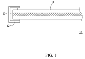
- FIG. 1 is a longitudinal sectional view of a conventional solar power module 10.
- the double sided foam tape 13 is used to increase the distance between the solar panel 11 and the aluminum alloy frame 12.
- the lower portion of the double sided foam tape 13 becomes thinner due to being compressed by the solar panel 11.
- the parasitic capacitance generated by the aluminum alloy frame 12 and the solar panel 11 becomes more and more.
- the improvement is limited. It is worth for the person skilled in the art to consider how to reduce the parasitic capacitance generated by the solar power module. Accordingly, the inventor of the present invention has devoted himself based on his many years of practical experiences to solve these problems.
- the primary object of the present invention is to provide a solar power module which can decrease parasitic capacitance effectively.
- the solar power module of the present invention comprises a solar panel, a metallic frame, a soft insulation glue material, and a hard insulation spacer.
- the solar panel is embedded in the metallic frame.
- the metallic frame comprises an upper portion, an intermediate portion, and a lower portion.
- the soft insulation glue material is adapted to wrap at least one portion of an edge of the solar panel.
- the soft insulation glue material is fixedly disposed in the metallic frame.
- the soft insulation glue material to wrap the solar panel is divided into an upper part, an intermediate part, and a lower part.
- the hard insulation spacer is disposed between the solar panel and the lower portion of the metallic frame.
- the hard insulation spacer separates the lower part of the soft insulation glue material from the metallic frame.
- the hard insulation spacer separates the lower part of the soft insulation glue material from the solar panel.
- the solar panel has a rectangular shape, the solar panel comprises a glass panel, a main layer, and a back panel, and the back panel includes a metallic film.
- the hard insulation spacer has a ⁇ -like shape, and the hard insulation spacer is disposed beneath the solar panel to surround the edge of the solar panel.
- either side of the hard insulation spacer has a width not less than a depth of the solar panel embedded into the metallic frame.
- the hard insulation spacer has a height greater than a critical height.
- the critical height is 0.5mm.
- the hard insulation spacer is made of polyethylene terephthalate (PET) or acryl.
- the soft insulation glue material is a waterproof glue material.
- FIG. 2 is a longitudinal sectional view of a solar power module 20 in accordance with a preferred embodiment of the present invention.
- FIG. 3 is an exploded view of the solar power module 20 in accordance with the preferred embodiment of the present invention.
- the solar power module 20 comprises a solar panel 21, a metallic frame 22, a soft insulation glue material 23, and a hard insulation spacer 24.
- the solar panel 21 may be a monocrystalline silicon solar cell, a polycrystalline silicon solar cell, or a thin-film solar cell.
- the solar panel 21 has a rectangular shape, and comprises a main layer 212, a glass panel 211, and a back panel 213.
- the metallic frame 22 comprises an upper portion 221, an intermediate portion 222, and a lower portion 223.
- the glass panel 211 is disposed on top of the main layer 212.
- the back panel 213 is disposed beneath the main layer 212.
- the soft insulation glue material 23 is adapted to wrap at least one portion of an edge of the solar panel 21.
- the soft insulation glue material 23 is to surround the edge of the solar panel 21.
- the soft insulation glue material 23 to wrap the solar panel 21 is divided into an upper part 231, an intermediate part 232, and a lower part 233.
- the solar panel 21 wrapped by the soft insulation glue material 23 is embedded into the metallic frame 22, so that the soft insulation glue material 23 is fixedly disposed in the metallic frame 22.
- the hard insulation spacer 24 is disposed beneath the lower part 233 of the soft insulation glue material 23 and attached to lower part 233 tightly.
- the hard insulation spacer 24 has a height greater than a critical height.
- the distance of the critical height is a safe distance capable of preventing parasitic capacitance between the metallic frame 22 and the solar panel 21.
- the critical height is 0.5mm.
- the critical height is 1 mm.
- the hard insulation spacer 24 can separate the lower part 233 of the soft insulation glue material 23 from the metallic frame 22 effectively.
- the hard insulation spacer 24 enables the solar panel 21 to be spaced at a safe distance from the lower portion 223 of the metallic frame 22, so that the solar panel 21 and the metallic frame 22 won't generate parasitic capacitance easily.
- the soft insulation glue material 23 can be a waterproof glue material, such as foam tape or butyl rubber.
- the hard insulation spacer 24 is made of polyethylene terephthalate (PET) or acryl.
- the metallic frame 22 is made of aluminum or aluminum alloy.
- the hard insulation spacer 24 has a ⁇ -like shape, referring to FIG. 3 .
- the hard insulation spacer 24 is disposed beneath the solar panel 21 to surround the edge of the solar panel 212. That is to say, the hard insulation spacer 24 is attached to the whole metallic frame 22.
- the width of either side of the hard insulation spacer 24 is not less than the depth of the solar panel 21 embedded into the metallic frame 22. For example, the width of one side of the hard insulation spacer 24 as shown in FIG. 4 (FIG.
- D4 is a longitudinal sectional view of the solar power module 20) is D2, and the depth of the solar panel 21 embedded into the metallic frame 22 is D1.
- D2 is greater than or equal to D1 (D2 ⁇ D1).
- FIG. 5 is a longitudinal sectional view of a solar power module 30 in accordance with another embodiment of the present invention.
- the solar power module 30 is derived from the solar power module 20.
- the back panel 313 of the solar panel 31 of the solar power module 30 further comprises a metallic film 313A therein to enhance the strength of the back panel 313.
- the solar power module 30 also has the soft insulation glue material 23 and the hard insulation spacer 24 to separate the back plate 313 from the metallic frame 22, such that the metallic film 313A inside the back plate 313 and the metallic frame 22 won't generate parasitic capacitance easily.
- the metallic film 313A is made of aluminum or aluminum alloy. As shown in FIG.
- the metallic film 313A and the metallic frame 22 are overlapped up and down, alternatively, the metallic film 313A is smaller in size and doesn't totally overlap over the metallic frame 22 (not shown in the drawing) further to lower the possibility of the parasitic capacitance generated by the metallic film 313A and the metallic frame 22.
- FIG. 6 is a longitudinal sectional view of a solar power module 40 in accordance with a further embodiment of the present invention.
- the solar power module 40 is derived from the solar power module 30.
- the solar power module 40 is substantially similar to the solar power module 30 with the exceptions described hereinafter.
- the hard insulation spacer 24 of the solar power module 30 is disposed beneath the lower part 233 of the soft insulation glue material 23, but the hard insulation spacer 44 of the solar power module 40 is disposed over the lower part 233 of the soft insulation glue material 23.
- the hard insulation spacer 44 of the solar power module 40 is to separate the lower part 233 of the soft insulation glue material 23 from the solar panel 31.
- the hard insulation spacer 44 enables the solar panel 21 to be spaced at a safe distance from the lower portion 223 of the metallic frame 22, so that the solar panel 21 and the metallic frame 22 won't generate parasitic capacitance easily, and the metallic film 313A and the metallic frame 22 won't generate parasitic capacitance easily.
Landscapes
- Photovoltaic Devices (AREA)
Applications Claiming Priority (1)
| Application Number | Priority Date | Filing Date | Title |
|---|---|---|---|
| TW105205174U TWM527612U (zh) | 2016-04-14 | 2016-04-14 | 太陽能模組 |
Publications (1)
| Publication Number | Publication Date |
|---|---|
| EP3236581A1 true EP3236581A1 (fr) | 2017-10-25 |
Family
ID=56551950
Family Applications (1)
| Application Number | Title | Priority Date | Filing Date |
|---|---|---|---|
| EP16177035.9A Withdrawn EP3236581A1 (fr) | 2016-04-14 | 2016-06-30 | Module d'énergie solaire |
Country Status (6)
| Country | Link |
|---|---|
| US (1) | US10312393B2 (fr) |
| EP (1) | EP3236581A1 (fr) |
| JP (1) | JP3208703U (fr) |
| CN (1) | CN206040660U (fr) |
| DE (1) | DE202016103473U1 (fr) |
| TW (1) | TWM527612U (fr) |
Families Citing this family (3)
| Publication number | Priority date | Publication date | Assignee | Title |
|---|---|---|---|---|
| CN108417655B (zh) * | 2018-03-28 | 2024-07-09 | 盐城天合国能光伏科技有限公司 | 一种反光散热高效平板太阳能电池薄型组件 |
| GB202119061D0 (en) * | 2021-12-29 | 2022-02-09 | Rec Solar Pte Ltd | Solar module |
| CN116435396A (zh) * | 2023-04-20 | 2023-07-14 | 中国科学院上海微系统与信息技术研究所 | 光伏背板、光伏背板的制作方法及光伏组件 |
Citations (3)
| Publication number | Priority date | Publication date | Assignee | Title |
|---|---|---|---|---|
| EP0860886A2 (fr) * | 1997-02-19 | 1998-08-26 | Canon Kabushiki Kaisha | Module de cellules solaires |
| JP2006100392A (ja) * | 2004-09-28 | 2006-04-13 | Msk Corp | パネル保持機構 |
| EP2595199A2 (fr) * | 2011-11-18 | 2013-05-22 | Hulk Energy Technology Co., Ltd. | Module de cellule solaire |
Family Cites Families (7)
| Publication number | Priority date | Publication date | Assignee | Title |
|---|---|---|---|---|
| US5460660A (en) * | 1993-07-21 | 1995-10-24 | Photon Energy, Inc. | Apparatus for encapsulating a photovoltaic module |
| US20090050195A1 (en) * | 2007-08-21 | 2009-02-26 | Sanyo Electric Co., Ltd. | Solar cell module |
| JP4285764B2 (ja) * | 2007-11-09 | 2009-06-24 | 昭和シェル石油株式会社 | 太陽電池モジュール |
| US20100065116A1 (en) * | 2008-08-13 | 2010-03-18 | Robert Stancel | Impact Resistant Thin-Glass Solar Modules |
| IN2012DN00387A (fr) * | 2009-06-15 | 2015-08-21 | Tenksolar Inc | |
| WO2012056941A1 (fr) * | 2010-10-28 | 2012-05-03 | 富士フイルム株式会社 | Module de cellules solaires et son procédé de fabrication |
| KR101665898B1 (ko) * | 2012-09-05 | 2016-10-12 | 피피지 인더스트리즈 오하이오 인코포레이티드 | 태양광 모듈 프레임 |
-
2016
- 2016-04-14 TW TW105205174U patent/TWM527612U/zh not_active IP Right Cessation
- 2016-05-25 CN CN201620488155.9U patent/CN206040660U/zh not_active Expired - Fee Related
- 2016-06-06 US US15/173,846 patent/US10312393B2/en active Active
- 2016-06-30 EP EP16177035.9A patent/EP3236581A1/fr not_active Withdrawn
- 2016-06-30 DE DE202016103473.6U patent/DE202016103473U1/de not_active Expired - Lifetime
- 2016-09-09 JP JP2016004406U patent/JP3208703U/ja not_active Expired - Fee Related
Patent Citations (3)
| Publication number | Priority date | Publication date | Assignee | Title |
|---|---|---|---|---|
| EP0860886A2 (fr) * | 1997-02-19 | 1998-08-26 | Canon Kabushiki Kaisha | Module de cellules solaires |
| JP2006100392A (ja) * | 2004-09-28 | 2006-04-13 | Msk Corp | パネル保持機構 |
| EP2595199A2 (fr) * | 2011-11-18 | 2013-05-22 | Hulk Energy Technology Co., Ltd. | Module de cellule solaire |
Also Published As
| Publication number | Publication date |
|---|---|
| CN206040660U (zh) | 2017-03-22 |
| US10312393B2 (en) | 2019-06-04 |
| JP3208703U (ja) | 2017-02-09 |
| DE202016103473U1 (de) | 2016-07-13 |
| US20170301812A1 (en) | 2017-10-19 |
| TWM527612U (zh) | 2016-08-21 |
Similar Documents
| Publication | Publication Date | Title |
|---|---|---|
| EP3236581A1 (fr) | Module d'énergie solaire | |
| JP5938584B2 (ja) | 太陽電池モジュール | |
| US20110226335A1 (en) | Solar cell module | |
| US9660572B2 (en) | Aluminum frame structure for packaging solar panel | |
| JP4515514B2 (ja) | 太陽電池モジュール | |
| US20180035554A1 (en) | Flexible display device | |
| WO2014130928A3 (fr) | Structures d'isolation de contraintes pour dispositifs électroniques extensibles | |
| JP5879537B2 (ja) | 太陽電池パネル、太陽電池モジュールおよび太陽電池モジュールの製造方法 | |
| TW201635575A (zh) | 可撓式太陽能板模組、其固定結構及其製造方法 | |
| WO2012109050A3 (fr) | Structures de terminaison de jonction, comprenant des extensions d'anneau de garde, ainsi que procédés de fabrication de dispositifs électroniques comportant celles-ci | |
| KR20120096175A (ko) | 태양전지 모듈용 프레임 시스템 | |
| PH12012501818A1 (en) | Fitted roofing material, clip and fitted roof structure | |
| EP2600426A3 (fr) | Appareil à cellule solaire | |
| EP2701204A3 (fr) | Cellule solaire et module solaire l'employant | |
| JPWO2016043137A1 (ja) | 太陽電池モジュール | |
| EP2995740A2 (fr) | Feuille de toit ondulé et ensemble photovoltaïque comprenant celle-ci | |
| US20140054194A1 (en) | Packaging assembly | |
| EP3263480A3 (fr) | Module de distribution de boisson et poche souple | |
| CN203376531U (zh) | 一种具有抗震性能的液晶显示屏 | |
| CN206524807U (zh) | 太阳电池模块及太阳电池模块用框体 | |
| WO2019062373A1 (fr) | Batterie souple | |
| JP2012182322A (ja) | 太陽電池モジュール及び太陽電池システム | |
| JP2016152332A (ja) | 太陽電池モジュール | |
| CN203351618U (zh) | 太阳能光伏组件用边框 | |
| WO2016115696A1 (fr) | Dispositif électronique |
Legal Events
| Date | Code | Title | Description |
|---|---|---|---|
| PUAI | Public reference made under article 153(3) epc to a published international application that has entered the european phase |
Free format text: ORIGINAL CODE: 0009012 |
|
| STAA | Information on the status of an ep patent application or granted ep patent |
Free format text: STATUS: REQUEST FOR EXAMINATION WAS MADE |
|
| 17P | Request for examination filed |
Effective date: 20160704 |
|
| AK | Designated contracting states |
Kind code of ref document: A1 Designated state(s): AL AT BE BG CH CY CZ DE DK EE ES FI FR GB GR HR HU IE IS IT LI LT LU LV MC MK MT NL NO PL PT RO RS SE SI SK SM TR |
|
| AX | Request for extension of the european patent |
Extension state: BA ME |
|
| STAA | Information on the status of an ep patent application or granted ep patent |
Free format text: STATUS: EXAMINATION IS IN PROGRESS |
|
| 17Q | First examination report despatched |
Effective date: 20190813 |
|
| STAA | Information on the status of an ep patent application or granted ep patent |
Free format text: STATUS: THE APPLICATION HAS BEEN WITHDRAWN |
|
| 18W | Application withdrawn |
Effective date: 20191126 |