EP3236703A1 - Funkressourcenmessverfahren in direktionalen drahtlosen netzwerken - Google Patents
Funkressourcenmessverfahren in direktionalen drahtlosen netzwerken Download PDFInfo
- Publication number
- EP3236703A1 EP3236703A1 EP17174660.5A EP17174660A EP3236703A1 EP 3236703 A1 EP3236703 A1 EP 3236703A1 EP 17174660 A EP17174660 A EP 17174660A EP 3236703 A1 EP3236703 A1 EP 3236703A1
- Authority
- EP
- European Patent Office
- Prior art keywords
- measurement
- directional channel
- station device
- channel quality
- indicate
- Prior art date
- Legal status (The legal status is an assumption and is not a legal conclusion. Google has not performed a legal analysis and makes no representation as to the accuracy of the status listed.)
- Granted
Links
Images


Classifications
-
- H—ELECTRICITY
- H04—ELECTRIC COMMUNICATION TECHNIQUE
- H04W—WIRELESS COMMUNICATION NETWORKS
- H04W24/00—Supervisory, monitoring or testing arrangements
- H04W24/10—Scheduling measurement reports ; Arrangements for measurement reports
-
- H—ELECTRICITY
- H04—ELECTRIC COMMUNICATION TECHNIQUE
- H04B—TRANSMISSION
- H04B17/00—Monitoring; Testing
- H04B17/20—Monitoring; Testing of receivers
- H04B17/24—Monitoring; Testing of receivers with feedback of measurements to the transmitter
-
- H—ELECTRICITY
- H04—ELECTRIC COMMUNICATION TECHNIQUE
- H04B—TRANSMISSION
- H04B17/00—Monitoring; Testing
- H04B17/30—Monitoring; Testing of propagation channels
- H04B17/309—Measuring or estimating channel quality parameters
- H04B17/346—Noise values
-
- H—ELECTRICITY
- H04—ELECTRIC COMMUNICATION TECHNIQUE
- H04B—TRANSMISSION
- H04B7/00—Radio transmission systems, i.e. using radiation field
- H04B7/02—Diversity systems; Multi-antenna system, i.e. transmission or reception using multiple antennas
- H04B7/04—Diversity systems; Multi-antenna system, i.e. transmission or reception using multiple antennas using two or more spaced independent antennas
- H04B7/06—Diversity systems; Multi-antenna system, i.e. transmission or reception using multiple antennas using two or more spaced independent antennas at the transmitting station
- H04B7/0613—Diversity systems; Multi-antenna system, i.e. transmission or reception using multiple antennas using two or more spaced independent antennas at the transmitting station using simultaneous transmission
- H04B7/0615—Diversity systems; Multi-antenna system, i.e. transmission or reception using multiple antennas using two or more spaced independent antennas at the transmitting station using simultaneous transmission of weighted versions of same signal
- H04B7/0617—Diversity systems; Multi-antenna system, i.e. transmission or reception using multiple antennas using two or more spaced independent antennas at the transmitting station using simultaneous transmission of weighted versions of same signal for beam forming
-
- H—ELECTRICITY
- H04—ELECTRIC COMMUNICATION TECHNIQUE
- H04W—WIRELESS COMMUNICATION NETWORKS
- H04W24/00—Supervisory, monitoring or testing arrangements
- H04W24/08—Testing, supervising or monitoring using real traffic
-
- H—ELECTRICITY
- H04—ELECTRIC COMMUNICATION TECHNIQUE
- H04W—WIRELESS COMMUNICATION NETWORKS
- H04W72/00—Local resource management
- H04W72/04—Wireless resource allocation
- H04W72/044—Wireless resource allocation based on the type of the allocated resource
- H04W72/0446—Resources in time domain, e.g. slots or frames
-
- H—ELECTRICITY
- H04—ELECTRIC COMMUNICATION TECHNIQUE
- H04W—WIRELESS COMMUNICATION NETWORKS
- H04W72/00—Local resource management
- H04W72/50—Allocation or scheduling criteria for wireless resources
- H04W72/54—Allocation or scheduling criteria for wireless resources based on quality criteria
- H04W72/542—Allocation or scheduling criteria for wireless resources based on quality criteria using measured or perceived quality
-
- H—ELECTRICITY
- H04—ELECTRIC COMMUNICATION TECHNIQUE
- H04B—TRANSMISSION
- H04B17/00—Monitoring; Testing
- H04B17/30—Monitoring; Testing of propagation channels
- H04B17/309—Measuring or estimating channel quality parameters
- H04B17/345—Interference values
-
- H—ELECTRICITY
- H04—ELECTRIC COMMUNICATION TECHNIQUE
- H04B—TRANSMISSION
- H04B7/00—Radio transmission systems, i.e. using radiation field
- H04B7/02—Diversity systems; Multi-antenna system, i.e. transmission or reception using multiple antennas
- H04B7/04—Diversity systems; Multi-antenna system, i.e. transmission or reception using multiple antennas using two or more spaced independent antennas
- H04B7/06—Diversity systems; Multi-antenna system, i.e. transmission or reception using multiple antennas using two or more spaced independent antennas at the transmitting station
- H04B7/0613—Diversity systems; Multi-antenna system, i.e. transmission or reception using multiple antennas using two or more spaced independent antennas at the transmitting station using simultaneous transmission
- H04B7/0615—Diversity systems; Multi-antenna system, i.e. transmission or reception using multiple antennas using two or more spaced independent antennas at the transmitting station using simultaneous transmission of weighted versions of same signal
- H04B7/0619—Diversity systems; Multi-antenna system, i.e. transmission or reception using multiple antennas using two or more spaced independent antennas at the transmitting station using simultaneous transmission of weighted versions of same signal using feedback from receiving side
-
- H—ELECTRICITY
- H04—ELECTRIC COMMUNICATION TECHNIQUE
- H04W—WIRELESS COMMUNICATION NETWORKS
- H04W84/00—Network topologies
- H04W84/18—Self-organising networks, e.g. ad-hoc networks or sensor networks
Definitions
- Wireless networks such as wireless personal area networks (WPANs), wireless local area networks (WLANs), and/or cellular telephony networks provide for a wide array of mobile communications services.
- WLANs wireless local area networks
- cellular telephony networks provide for a wide array of mobile communications services.
- wireless networks are under development for the 60 GHz radio frequency (RF) band.
- RF radio frequency
- MAC media access control
- TDMA time division multiple access
- scheduled media access techniques are typically not as robust as contention-based media access techniques.
- CSMA/CA carrier sense multiple access with collision avoidance
- One way to promote robustness involves the exchange of information between devices regarding the wireless environment. More particularly, such information provides for scheduled allocations that promote robust network operation.
- Embodiments provide techniques for radio resource measurement (RRM) that support directionality, as well as scheduled media access techniques. For instance, embodiments may transmit a measurement request from a first device to a second device that directs the second device to take one or more measurements of a wireless channel. This measurement request may include various characteristics for the one or more measurements. For example, the measurement request may indicate at least one directional parameter and at least one timing parameter for the one or more measurements. In response to the request, the first device receives a measure report that includes measured values for each of the one or more measurements.
- RRM radio resource measurement
- RRM techniques do not support directionality and scheduled access (e.g., TDMA).
- TDMA Time Division Multiple Access
- IEEE 802.11k Amendment to the IEEE 802.11-2007 Standard provides RRM schemes.
- these schemes were developed under the assumption of a CSMA/CA MAC and an omni-directional transmission mode.
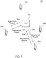
- FIG. 1 is a diagram of an exemplary operational environment 100 that may employ the techniques described herein.
- This environment includes a central controller device (PCP) 102, and multiple stations (STAs) 104a-d. These devices may be implemented in any combination of hardware and/or software. In general operation, these devices may communicate wirelessly with each other. Moreover, in embodiments, these devices may employ multiple beams and/or directional transmissions.
- PCP central controller device
- STAs stations
- PCP 102 performs various control operations, including resource allocations for STAs 104a-d.
- PCP 102 may manage resources within a repeating period called a TDMA frame (also known as Beacon Interval or Superframe). This may involve allocating time slots within the TDMA frame to STAs 104a-d.
- TDMA frame also known as Beacon Interval or Superframe
- Such allocations may employ spatial reuse. More particularly, such allocations may overlap (completely or partially) in time.
- allocations made by PCP 102 may be based on requests received from STAs 104a-d. In making such allocations, PCP 102 may consider characteristics regarding the wireless environment of STAs 104a-d. Details involving the determination of such characteristics are provided below.
- STAs 104a-d may wirelessly communicate in accordance with resource allocations performed by PCP 102. These communications may involve transmissions between STAs 104. Also, these communications may involve exchanging transmissions with PCP 102. For example, PCP 102 may relay communications traffic between STAs. Further, PCP 102 may provide STAs 104a-d with access to one or more wireless networks (e.g., the Internet and/or wired telephony networks).
- wireless networks e.g., the Internet and/or wired telephony networks.
- PCP 102 may consider characteristics regarding the wireless environment of STAs 104a-104d. To determine such characteristics, PCP 102 may gather information from STAs 104a-d. More particularly, PCP 102 may transmit requests to STAs 104a-d. Each of such requests may direct the receiving STA to conduct particular measurements. In turn, the recipient STA conducts the measurement(s) and transmits a report back to PCP 102. From such reports, PCP 102 may perform resource allocations that consider factors, such as interference mitigation, network stability, and so forth. For example, based on such received report(s), PCP 102 may determine whether to make allocations involving spatial reuse.
- factors such as interference mitigation, network stability, and so forth.
- FIG. 1 shows PCP 102 sending measurement requests 120a and 120b to STA 104a and 104b, respectively.
- STAs 104a and 104b send measurement reports 122a and 122b to PCP 102.
- These messages are shown for purposes of illustration, and not limitation. Thus, messages may be sent to any combination of STAs 104a-d in any number and/or sequence.
- a device may make allocations based on the amount of isolation among particular beams (as well as other information). For example, a beam pairing must exhibit a sufficiently low amount of isolation to support a wireless link. Further, the device may use such isolation information to establish multiple allocations that reuse resources (e.g., time and/or frequency and/or space). More particularly, information included in such measurement reports may be used to establish a high degree of isolation between each allocation (so that the interference is effectively managed). Examples of varying isolation levels are illustrated below with reference to FIG. 2 .
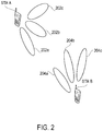
- FIG. 2 is a diagram showing an exemplary wireless arrangement between two devices.
- FIG. 2 shows a first station ("STA A") and a second station ("STA B"). These stations may be employed in the context of FIG. 1 (e.g., each as one STAs 104a-d).
- FIG. 2 shows that STA A provides transmit beams 202a-c. Also, FIG. 2 shows that STA B provides receive beams 204a-c. These features are shown for purposes of illustration and not limitation. Through beams 202a-c, STA A may engage in one or more directional transmissions. Similarly, through beams 204a-c, STA B may receive transmissions from different directions.
- FIG. 2 shows nine different pairings of transmit and receive beams between STA A and STA B. Each of these pairings exhibits different levels of isolation. For instance, there is a low amount of isolation between beams 202a and 204a. This is because these beams are substantially aligned (or overlapping). In contrast, there is a high amount of isolation between beams 202c and 204c. This is because these beams are unaligned (or non-overlapping). In embodiments, such levels of isolation may be determined through measurements performed by stations (e.g., STAs 104a-d). Such measurements may be made in response to requests made by a controlling station (e.g., PCP 102).
- stations e.g., STAs 104a-d
- Such measurements may be made in response to requests made by a controlling station (e.g., PCP 102).
- FIG. 1 Some of the figures may include a logic flow. Although such figures presented herein may include a particular logic flow, it can be appreciated that the logic flow merely provides an example of how the general functionality as described herein can be implemented. Further, the given logic flow does not necessarily have to be executed in the order presented unless otherwise indicated. In addition, the given logic flow may be implemented by a hardware element, a software element executed by a processor, or any combination thereof. The embodiments are not limited to this context.
- FIG. 3 illustrates an embodiment of a logic flow.
- FIG. 3 illustrates a logic flow 300, which may be representative of operations executed by one or more embodiments. This flow is described in the context of FIG. 1 . However, this flow may be employed in other contexts.
- a first device wirelessly sends a measurement request to a second device.
- This request directs the second device to perform one or more measurements of a wireless channel.
- the first device may be a coordinator device for a wireless network (e.g., PCP 102), and the second device may be a user device (e.g., one of STAs 104a-d).
- this request may be a quality histogram request, as described below with reference to FIG. 4 .
- embodiments may employ other request formats.
- the request may specify one or more characteristics for these one or more measurements.
- the request may indicate particular directional and timing characteristics for the measurement(s).
- directional characteristics include (but are not limited to) a particular remote device to which the measurement(s) are to be directed, and a beam (e.g., a receive beam) through which the second device is to perform the measurement(s).
- timing characteristics include (but are not limited to) a measurement start time, a measurement period duration, and a number of measurements to be taken during the measurement period.
- the request may specify when the type of measurement(s) to be taken.
- Exemplary measurement types include a determination of an Average Noise plus Interference Power Indicator (ANIPI), and/or determination of a Received Signal to Noise Indicator (RSNI). Embodiments, however, are not limited to these measurement types
- the second device wirelessly receives the measurement request. Following this, at a block 306, the second device performs one or more measurements in accordance with the request.
- the remote device wirelessly sends a response (also referred to as a measurement report) to the first device containing the measurement(s).
- this response may be a quality histogram report, as described below with reference to FIG. 5 .
- embodiments may employ other response formats.
- the first device receives the response at a block 310. Then, at a block 312, the first device may make one or more resource allocations based on information provided in the response. As described above with reference to FIG. 1 , this may involve allocating one or more time slots within a TDMA frame. However, embodiments are not limited to TDMA media access techniques.
- FIG. 4 is a diagram showing an exemplary format 400 of a channel quality histogram format request.
- This format includes multiple fields.
- a regulatory class field 402 provides information regarding regulated parameters, such as channel frequency, channel spacing, power limits, and so forth.
- a channel number field 404 provides information regarding the channel for which measurements are to be taken.
- Embodiments may format fields 402 and 404 in accordance with Annex J of the IEEE 802.11k Amendment to the IEEE 802.11-2007 Standard.
- Each of fields 402 and 404 may be one octet in size. However, other sizes may be employed.
- format 400 further includes a STAID field 406 and a Beam ID field 408. These fields introduce directionality support for RRM measurements.
- STAID field 406 indicates a STA (e.g., by its MAC address) towards which the RRM request applies. For example, if the measuring STA is beamformed with the STA identified by STAID field 406, then the measurement shall be carried out directionally towards identified STA.
- STAID field 406 may be set to a broadcast ID (BcastID), in which case the measuring STA will do so through an omni directional pattern.
- STAID field 406 may be in various formats.
- STAID filed 406 indicates a MAC address of a STA.
- FIG. 4 shows that STAID ID field 406 may be one octet in size, which may be an Association ID obtained by the STA once it associated with the PCP. However, other types of identifiers and sizes may be employed.
- Beam ID field 408 indicates a beam for which the corresponding measurement request applies. For example, if source and destination STAs have multiple beams between them, Beam ID field 408 identifies one of them. A value of zero (0) in this field indicates that any beam may be used for this measurement. As indicated in FIG. 4 , Beam ID field 408 may be one octet in size. However, other sizes may be employed.
- Measurement method field 410 indicates the method to be used by the measuring STA in carrying the measurement request, as well as in reporting back to the PCP in the corresponding measurement report.
- the conventions provided in the IEEE 802.11k Amendment to the IEEE 802.11-2007 Standard may be employed. For example, when field 410 is set to zero (0), Average Noise plus Interference Power Indicator (ANIPI) is designated. However, when this field is set to one (1), Received Signal to Noise Indicator (RSNI) is designated. Other values of measurement field 410 may be reserved for other designations.
- Measurement method field 410 may be one octet in size. However, other sizes may be employed. Moreover, embodiments are not limited to ANIPI and RSNI. Thus, in embodiments, measurement method field 410 may indicate other measurement types.
- Measurement start time field 412 provides RRM support for scheduled access MAC protocols (e.g., TDMA). In the IEEE 802.11k Amendment to the IEEE 802.11-2007 Standard, no Measurement Start Time is defined. Rather a Randomization Interval is included which suits a CSMA/CA MAC protocol. However, for scheduled MAC protocols, a specific Measurement Start Time field is required. Thus, measurement start time field 412 indicates a time when the requested measurement is to commence. In embodiments, a value of 0 indicates that the requested measurement shall start immediately. Measurement start time field 412 may be eight octets in size. However, other sizes may be employed.
- Measurement duration field 414 indicates a duration of the requested measurement. In embodiments, such duration may be either mandatory or preferred. As indicated in FIG. 4 , measurement duration field may be two octets in size.
- Number of time blocks field 416 provides a capability that is advantageous for spatial reuse and interference mitigation, but which is not currently supported in the IEEE 802.11k Amendment to the IEEE 802.11-2007 Standard.
- this field indicates the number of time blocks within the total Measurement Duration.
- a ratio between the measurement duration and the number of time blocks i.e., the measurement duration divided by the number of Time blocks
- field 416 may be one octet in size. However, other sizes may be employed.
- format 400 may include a field 418 (of variable size) to convey optional information sub-elements.
- this field may employ the same convention, as provided by the IEEE 802.11k Amendment to the IEEE 802.11-2007 Standard.
- FIG. 5 is a diagram showing an exemplary format 500 of a channel quality histogram format report.
- This format includes multiple fields.
- regulatory class field 502 and channel number field 504 provide information, as described above with reference to fields 402 and 404 of FIG. 4 .
- This information may be formatted as defined in Annex J of the IEEE 802.11k Amendment to the IEEE 802.11-2007 Standard.
- Each of fields 502 and 504 may be one octet in size. However, other sizes may be employed.
- STAID field 506 and Beam ID field 508 indicate the directionality aspect of the measurement report, as described above with reference to fields 406 and 408 of FIG. 4 .
- STAID field 506 indicates the STA towards which the measurement applies and Beam ID field 508 indicates the beam that was used to perform the measurement.
- Beam ID field 508 indicates the beam that was used to perform the measurement.
- STAID field 506 and Beam ID field 508 may each be one octet in size. However, other sizes may be employed.
- Measurement method field 510 measurement start time field 512, measurement duration field 514, and number of time blocks 516 are employed as described above with reference to fields 410-416 of FIG. 4 .
- FIG. 5 shows that format 500 includes multiple measurement fields.
- FIG. 5 shows measurement fields 518 1 -518 N that correspond to each of N time blocks specified in the corresponding channel quality histogram request.
- Each of measurement fields 518 1 -518 N carries an actual measured value (e.g., an ANIPI value or an average RSNI value).
- format 500 may include a field 518 (of variable size) to convey optional information sub-elements.
- this field may employ the same convention, as provided by the IEEE 802.11k Amendment to the IEEE 802.11-2007 Standard.
- FIG. 6 is a diagram of an implementation 600 that may be included in a wireless device, such PCP 102 and/or STAs 104a-d of FIG. 1 . This implementation, however, may be also employed in other contexts.
- Implementation 600 may include various elements. For example, FIG. 6 shows implementation 600 including multiple antennas 602a-c, a transceiver module 604, a host module 606, a measurement module 607, and a resource allocation module 608. These elements may be implemented in hardware, software, or any combination thereof.
- Antennas 602a-c provide for the exchange of wireless signals with remote devices. Although three antennas are depicted, any number of antennas may be employed. Also, embodiments may employ one or more transmit antennas and one or more receive antennas. Such multiple antenna arrangements may be employed for beamforming. For instance, a weight may be set in each antenna may such that the combined output signal provides a corresponding beam.
- transceiver module 604 includes a transmitter portion 610, and a receiver portion 612. During operation, transceiver module 604 provides an interface between antennas 602a-c and other elements, such as host module 606, measurement module 607, and/or resource allocation module 608. For instance, transmitter portion 610 receives symbols from such elements, and generates corresponding signals for wireless transmission by one or more of antennas 602a-c. This may involve operations, such as modulation, amplification, and/or filtering. However, other operations may be employed.
- receiver portion 612 obtains signals received by one or more of antennas 602a-c and generates corresponding symbols.
- these symbols may be provided to elements, such as host module 606, measurement module 607, and/or resource allocation module 608.
- This generation of symbols may involve operations, including (but not limited to) demodulation, amplification, and/or filtering.
- the signals generated and received by transceiver module 604 may be in various formats. For instance, these signals may be modulated in accordance with an orthogonal frequency division multiplexing (OFDM) scheme or a Single Carrier (SC) scheme. However, other schemes and formats (e.g., QPSK, BPSK, FSK, etc.) may be employed.
- OFDM orthogonal frequency division multiplexing
- SC Single Carrier
- transmitter portion 610 and receiver portion 612 may each include various components, such as modulators, demodulators, amplifiers, filters, buffers, upconverters, and/or downconveters.
- components may be implemented in hardware (e.g., electronics), software, or any combination thereof.
- transceiver module 604 may form messages or information associated with one or more protocols, and/or with one or more user applications. Thus, these elements may perform operations corresponding to such protocol(s) and/or user application(s).
- Exemplary user applications include telephony, messaging, e-mail, web browsing, content (e.g., video and audio) distribution/reception, and so forth.
- transceiver module 604 may employ various access techniques. For example, transceiver module 604 may employ a scheduled MAC technique, such as TDMA. Embodiments, however, are not limited to such techniques.
- Measurement module 607 may perform measurements of wireless resources. Such resources may be specified in accordance with requests received (through transceiver module 604) from a remote device, such as PCP 102 or an IEEE 802.11 access point (AP). As described above, such measurements may be of average noise plus interference power (to provide an ANIPI), and/or of received signal to noise Indicator (to provide an RSNI). However, embodiments are not limited to these measurements. Thus, other wireless channel measurements (e.g., measurements involving any combination of signal power, interference power, and/or noise power) may be made.
- Measurements made by measurement module 607 may be from hard symbols received from transceiver module 604 (e.g., based on a bit error rate determined through comparison with a predetermined sequence). Also, such measurements may be based on soft symbols generated by transceiver module 604 from received wireless signals. Moreover, such measurements may be generated from un-demodulated signals provided by transceiver module.
- measurement module 607 may generate a report message that indicates such measurements. This report may be transmitted to the remote device through transceiver module 604.
- resource allocation module 608 may perform resource allocation techniques described herein. For example, based on received measurements, allocation module 608 may allocate portions of a communications resource (e.g., time slots within a TDMA frame). Such allocation may include employ reuse that where sufficient isolation exists. Such isolation may be determined through measurements received from remote stations (through transceiver module 604). Allocations may be communicated to remote devices (through transceiver module 604) in control messages.
- a communications resource e.g., time slots within a TDMA frame.
- Such allocation may include employ reuse that where sufficient isolation exists. Such isolation may be determined through measurements received from remote stations (through transceiver module 604). Allocations may be communicated to remote devices (through transceiver module 604) in control messages.
- various embodiments may be implemented using hardware elements, software elements, or any combination thereof.
- hardware elements may include processors, microprocessors, circuits, circuit elements (e.g., transistors, resistors, capacitors, inductors, and so forth), integrated circuits, application specific integrated circuits (ASIC), programmable logic devices (PLD), digital signal processors (DSP), field programmable gate array (FPGA), logic gates, registers, semiconductor device, chips, microchips, chip sets, and so forth.
- Examples of software may include software components, programs, applications, computer programs, application programs, system programs, machine programs, operating system software, middleware, firmware, software modules, routines, subroutines, functions, methods, procedures, software interfaces, application program interfaces (API), instruction sets, computing code, computer code, code segments, computer code segments, words, values, symbols, or any combination thereof.
- software may include software components, programs, applications, computer programs, application programs, system programs, machine programs, operating system software, middleware, firmware, software modules, routines, subroutines, functions, methods, procedures, software interfaces, application program interfaces (API), instruction sets, computing code, computer code, code segments, computer code segments, words, values, symbols, or any combination thereof.
- API application program interfaces
- Some embodiments may be implemented, for example, using a storage medium or article which is machine readable.
- the storage medium may store an instruction or a set of instructions that, if executed by a machine, may cause the machine to perform a method and/or operations in accordance with the embodiments.
- Such a machine may include, for example, any suitable processing platform, computing platform, computing device, processing device, computing system, processing system, computer, processor, or the like, and may be implemented using any suitable combination of hardware and/or software.
- the storage medium or article may include, for example, any suitable type of memory unit, memory device, memory article, memory medium, storage device, storage article, storage medium and/or storage unit, for example, memory, removable or non-removable media, erasable or non-erasable media, writeable or re-writeable media, digital or analog media, hard disk, floppy disk, Compact Disk Read Only Memory (CD-ROM), Compact Disk Recordable (CD-R), Compact Disk Rewriteable (CD-RW), optical disk, magnetic media, magneto-optical media, removable memory cards or disks, various types of Digital Versatile Disk (DVD), a tape, a cassette, or the like.
- memory removable or non-removable media, erasable or non-erasable media, writeable or re-writeable media, digital or analog media, hard disk, floppy disk, Compact Disk Read Only Memory (CD-ROM), Compact Disk Recordable (CD-R), Compact Disk Rewriteable (CD-RW), optical disk, magnetic media,
- the instructions may include any suitable type of code, such as source code, compiled code, interpreted code, executable code, static code, dynamic code, encrypted code, and the like, implemented using any suitable high-level, low-level, object-oriented, visual, compiled and/or interpreted programming language.
Landscapes
- Engineering & Computer Science (AREA)
- Computer Networks & Wireless Communication (AREA)
- Signal Processing (AREA)
- Quality & Reliability (AREA)
- Physics & Mathematics (AREA)
- Electromagnetism (AREA)
- Mobile Radio Communication Systems (AREA)
Applications Claiming Priority (3)
| Application Number | Priority Date | Filing Date | Title |
|---|---|---|---|
| US12/459,264 US8843073B2 (en) | 2009-06-26 | 2009-06-26 | Radio resource measurement techniques in directional wireless networks |
| EP10792522.4A EP2446659B1 (de) | 2009-06-26 | 2010-06-14 | Funkressourcenmessverfahren in direktionalen drahtlosen netzwerken |
| PCT/US2010/038499 WO2010151448A2 (en) | 2009-06-26 | 2010-06-14 | Radio resource measurement techniques in directional wireless networks |
Related Parent Applications (2)
| Application Number | Title | Priority Date | Filing Date |
|---|---|---|---|
| EP10792522.4A Division-Into EP2446659B1 (de) | 2009-06-26 | 2010-06-14 | Funkressourcenmessverfahren in direktionalen drahtlosen netzwerken |
| EP10792522.4A Division EP2446659B1 (de) | 2009-06-26 | 2010-06-14 | Funkressourcenmessverfahren in direktionalen drahtlosen netzwerken |
Publications (2)
| Publication Number | Publication Date |
|---|---|
| EP3236703A1 true EP3236703A1 (de) | 2017-10-25 |
| EP3236703B1 EP3236703B1 (de) | 2019-02-20 |
Family
ID=43381313
Family Applications (2)
| Application Number | Title | Priority Date | Filing Date |
|---|---|---|---|
| EP10792522.4A Active EP2446659B1 (de) | 2009-06-26 | 2010-06-14 | Funkressourcenmessverfahren in direktionalen drahtlosen netzwerken |
| EP17174660.5A Active EP3236703B1 (de) | 2009-06-26 | 2010-06-14 | Funkressourcenmessverfahren in direktionalen drahtlosen netzwerken |
Family Applications Before (1)
| Application Number | Title | Priority Date | Filing Date |
|---|---|---|---|
| EP10792522.4A Active EP2446659B1 (de) | 2009-06-26 | 2010-06-14 | Funkressourcenmessverfahren in direktionalen drahtlosen netzwerken |
Country Status (7)
| Country | Link |
|---|---|
| US (3) | US8843073B2 (de) |
| EP (2) | EP2446659B1 (de) |
| JP (1) | JP5571181B2 (de) |
| KR (1) | KR101347422B1 (de) |
| BR (2) | BR122017017264B1 (de) |
| SG (1) | SG175952A1 (de) |
| WO (1) | WO2010151448A2 (de) |
Families Citing this family (10)
| Publication number | Priority date | Publication date | Assignee | Title |
|---|---|---|---|---|
| US8843073B2 (en) | 2009-06-26 | 2014-09-23 | Intel Corporation | Radio resource measurement techniques in directional wireless networks |
| KR101764888B1 (ko) * | 2010-02-16 | 2017-08-16 | 한국전자통신연구원 | 광대역 근거리 무선 통신 장치 및 방법 |
| KR102159660B1 (ko) | 2011-12-08 | 2020-09-28 | 인터디지탈 패튼 홀딩스, 인크 | 복수의 무선 액세스 기술을 사용한 통신 |
| US9425935B2 (en) | 2012-06-26 | 2016-08-23 | Lg Electronics Inc. | Method and user equipment for performing radio resource management, and method and base station for requesting radio resource management |
| US9712262B2 (en) | 2013-01-09 | 2017-07-18 | Lg Electronics Inc. | Method and apparatus for performing measurement in wireless communication system |
| US20170064583A1 (en) * | 2014-03-05 | 2017-03-02 | Interdigital Patent Holdings, Inc. | Pcp handover in a mesh network after a change of role of a station associated with a first node receiving from another node an indication of association |
| JP6433260B2 (ja) * | 2014-11-19 | 2018-12-05 | パナソニック株式会社 | ワイヤレス通信システムにおける空間共有の方法 |
| EP3518602B1 (de) | 2017-12-01 | 2021-02-24 | LG Electronics Inc. -1- | Verfahren zum senden und empfangen von kanalmessungsinformationen in einem drahtlos-lan-system und vorrichtung dafür |
| CN113453268B (zh) * | 2020-03-26 | 2023-06-02 | 华为技术有限公司 | 空间复用的方法、装置、计算机可读存储介质和芯片 |
| EP4260583A2 (de) * | 2020-12-14 | 2023-10-18 | InterDigital Patent Holdings, Inc. | Verfahren und verfahren für multi-sta-unterstützte erfassung |
Citations (3)
| Publication number | Priority date | Publication date | Assignee | Title |
|---|---|---|---|---|
| US20060063492A1 (en) * | 2004-09-10 | 2006-03-23 | Interdigital Technology Corporation | Measurement support for a smart antenna in a wireless communication system |
| WO2006031495A2 (en) * | 2004-09-10 | 2006-03-23 | Interdigital Technology Corporation | Implementing a smart antenna in a wireless local area network |
| US20070002757A1 (en) * | 2003-05-09 | 2007-01-04 | Koninklijke Philips Electronics N.V. | System and method for specifying measurement request start time |
Family Cites Families (35)
| Publication number | Priority date | Publication date | Assignee | Title |
|---|---|---|---|---|
| FI111113B (fi) | 1999-11-18 | 2003-05-30 | Nokia Corp | Mittaustiedon välittäminen tiedonsiirtojärjestelmässä |
| JP3300324B2 (ja) | 2000-02-28 | 2002-07-08 | 株式会社ワイ・アール・ピー移動通信基盤技術研究所 | 信号対雑音干渉電力比推定装置 |
| JP3732792B2 (ja) | 2002-03-12 | 2006-01-11 | 株式会社東芝 | 無線通信システム及び無線基地局装置及び無線端末装置 |
| US7123924B2 (en) * | 2002-06-28 | 2006-10-17 | Interdigital Technology Corporation | Method and system for determining the speed and position of a mobile unit |
| US7738848B2 (en) * | 2003-01-14 | 2010-06-15 | Interdigital Technology Corporation | Received signal to noise indicator |
| KR100665425B1 (ko) * | 2003-03-08 | 2007-01-04 | 삼성전자주식회사 | 이동 통신 시스템에서 핸드오버를 수행하는 시스템 및 방법 |
| KR100689566B1 (ko) * | 2003-03-08 | 2007-03-02 | 삼성전자주식회사 | 광대역 무선 접속 통신 시스템에서 초기 레인징을 이용한핸드오프 시스템 및 방법 |
| KR100606129B1 (ko) | 2003-04-30 | 2006-07-28 | 삼성전자주식회사 | 광대역 무선 접속 통신 시스템에서 채널 품질 측정 및보고 방법 |
| JP3880554B2 (ja) * | 2003-07-18 | 2007-02-14 | 松下電器産業株式会社 | 空間分割多重アクセス方式ワイヤレス媒体アクセスコントローラ |
| GB2404820B (en) * | 2003-08-06 | 2005-07-20 | Toshiba Res Europ Ltd | Improved wireless local area network security |
| DE102004028703A1 (de) * | 2004-06-14 | 2005-12-29 | Siemens Ag | Verfahren zur Zuweisung von Übertragungskapazitäten bei einer Signalübertragung, Basisstation und mobiles Endgerät |
| US20060120310A1 (en) | 2004-12-03 | 2006-06-08 | Interdigital Technology Corporation | Method for improving wireless network performance in a multi-cell communication network |
| JP2006230860A (ja) | 2005-02-28 | 2006-09-07 | Omron Healthcare Co Ltd | 薬包ケース及び服薬用管理装置 |
| CN100431386C (zh) * | 2005-05-12 | 2008-11-05 | 上海原动力通信科技有限公司 | 同频多小区终端来波方向的估计方法 |
| US7869809B2 (en) * | 2005-05-13 | 2011-01-11 | Intel Corporation | Radio resource measurement and estimation |
| US20080219201A1 (en) * | 2005-09-16 | 2008-09-11 | Koninklijke Philips Electronics, N.V. | Method of Clustering Devices in Wireless Communication Network |
| WO2007031855A2 (en) * | 2005-09-16 | 2007-03-22 | Nokia Corporation | Techniques to provide measurement pilot transmission information in wireless networks |
| US7515878B2 (en) * | 2005-09-21 | 2009-04-07 | Broadcom Corporation | Method and system for greedy user group selection with range reduction for FDD multiuser MIMO downlink transmission with finite-rate channel state information feedback |
| ATE400932T1 (de) * | 2005-10-31 | 2008-07-15 | Mitsubishi Electric Corp | Verfahren zur steuerung der übertragung von nachrichtensignalen |
| US7693108B2 (en) | 2006-08-01 | 2010-04-06 | Intel Corporation | Methods and apparatus for providing a handover control system associated with a wireless communication network |
| CN101690015A (zh) * | 2007-07-06 | 2010-03-31 | Lg电子株式会社 | 无线通信系统中的无线电测量过程 |
| US8089947B2 (en) | 2007-08-31 | 2012-01-03 | Intel Corporation | Spatial reuse in directional antenna systems |
| FR2921217B1 (fr) * | 2007-09-14 | 2016-11-25 | Eads Secure Networks | Systeme de radiocommunications large bande, station recptrice complementaire, et procede d'optimisation d'une liaison de donnees dans un systeme de radiocommunications. |
| JP5392091B2 (ja) | 2007-11-19 | 2014-01-22 | 日本電気株式会社 | 無線通信システム及び方法 |
| US8134924B2 (en) * | 2007-11-27 | 2012-03-13 | Qualcomm Incorporated | Methods and apparatus related to scheduling in a wireless communications system using shared air link resources for traffic |
| US8274930B2 (en) * | 2008-03-10 | 2012-09-25 | Mitsubishi Electric Research Laboratories, Inc. | Analog beamforming to reduce interference in WiMAX networks |
| US20090233635A1 (en) | 2008-03-11 | 2009-09-17 | Li Guoqing C | Discovering neighbors in wireless personal area networks |
| US7978659B2 (en) * | 2008-03-11 | 2011-07-12 | Intel Corporation | Method and apparatus of connectivity recovery in a wireless network |
| US8477716B2 (en) * | 2008-05-22 | 2013-07-02 | Motorola Solutions, Inc. | Method for facilitating sharing of channel information in a wireless communication network |
| US9036563B2 (en) * | 2008-07-22 | 2015-05-19 | Mediatek Inc. | Method for achieving frequency reuse in wireless communications systems |
| US8194604B2 (en) * | 2008-09-08 | 2012-06-05 | Motorola Mobility, Inc. | Wireless local area network |
| US8554200B2 (en) * | 2008-09-12 | 2013-10-08 | Nokia Corporation | Method and apparatus for providing interference measurements for device to-device communication |
| US9178593B1 (en) * | 2009-04-21 | 2015-11-03 | Marvell International Ltd. | Directional channel measurement and interference avoidance |
| US8032167B2 (en) * | 2009-05-07 | 2011-10-04 | Broadcom Corporation | Multimode control device for allocating resources to communication devices that use differing protocols and methods for use therewith |
| US8843073B2 (en) | 2009-06-26 | 2014-09-23 | Intel Corporation | Radio resource measurement techniques in directional wireless networks |
-
2009
- 2009-06-26 US US12/459,264 patent/US8843073B2/en active Active
-
2010
- 2010-06-14 KR KR1020117030790A patent/KR101347422B1/ko active Active
- 2010-06-14 EP EP10792522.4A patent/EP2446659B1/de active Active
- 2010-06-14 SG SG2011082195A patent/SG175952A1/en unknown
- 2010-06-14 BR BR122017017264-6A patent/BR122017017264B1/pt active IP Right Grant
- 2010-06-14 EP EP17174660.5A patent/EP3236703B1/de active Active
- 2010-06-14 JP JP2012516165A patent/JP5571181B2/ja active Active
- 2010-06-14 BR BRPI1008568-8A patent/BRPI1008568B1/pt active IP Right Grant
- 2010-06-14 WO PCT/US2010/038499 patent/WO2010151448A2/en not_active Ceased
-
2014
- 2014-08-22 US US14/466,375 patent/US9538412B2/en active Active
-
2016
- 2016-11-25 US US15/361,161 patent/US10771997B2/en active Active
Patent Citations (3)
| Publication number | Priority date | Publication date | Assignee | Title |
|---|---|---|---|---|
| US20070002757A1 (en) * | 2003-05-09 | 2007-01-04 | Koninklijke Philips Electronics N.V. | System and method for specifying measurement request start time |
| US20060063492A1 (en) * | 2004-09-10 | 2006-03-23 | Interdigital Technology Corporation | Measurement support for a smart antenna in a wireless communication system |
| WO2006031495A2 (en) * | 2004-09-10 | 2006-03-23 | Interdigital Technology Corporation | Implementing a smart antenna in a wireless local area network |
Non-Patent Citations (2)
| Title |
|---|
| "IEEE Standard for Information technology-- Local and metropolitan area networks-- Specific requirements-- Part 11: Wireless LAN Medium Access Control (MAC)and Physical Layer (PHY) Specifications Amendment 1: Radio Resource Measurement of Wireless LANs;IEEE Std 802.11k-2008 (Amendment to IEEE Std 802", 802.11K-2008 - IEEE STANDARD FOR INFORMATION TECHNOLOGY-- LOCAL AND METROPOLITAN AREA NETWORKS-- SPECIFIC REQUIREMENTS-- PART 11: WIRELESS LAN MEDIUM ACCESS CONTROL (MAC)AND PHYSICAL LAYER (PHY) SPECIFICATIONS AMENDMENT 1: RADIO RESOURCE MEASUREMENT, 12 June 2008 (2008-06-12), pages 1 - 244, XP017694822, ISBN: 978-0-7381-5420-6 * |
| INTERDIGITAL COMMUNICATIONS: "Advancedantennas ; 11-05-0435-02-000k-advancedantennas", IEEE DRAFT; 11-05-0435-02-000K-ADVANCEDANTENNAS, IEEE-SA MENTOR, PISCATAWAY, NJ USA, vol. 802.11k, no. 2, 20 July 2005 (2005-07-20), pages 1 - 20, XP017689197 * |
Also Published As
| Publication number | Publication date |
|---|---|
| WO2010151448A3 (en) | 2011-04-21 |
| US8843073B2 (en) | 2014-09-23 |
| US10771997B2 (en) | 2020-09-08 |
| SG175952A1 (en) | 2011-12-29 |
| US9538412B2 (en) | 2017-01-03 |
| WO2010151448A2 (en) | 2010-12-29 |
| JP5571181B2 (ja) | 2014-08-13 |
| BRPI1008568A2 (pt) | 2016-03-15 |
| EP2446659B1 (de) | 2018-07-25 |
| JP2012531102A (ja) | 2012-12-06 |
| EP2446659A2 (de) | 2012-05-02 |
| KR101347422B1 (ko) | 2014-01-02 |
| US20100331028A1 (en) | 2010-12-30 |
| KR20120016288A (ko) | 2012-02-23 |
| BRPI1008568B1 (pt) | 2021-02-09 |
| US20170134979A1 (en) | 2017-05-11 |
| EP3236703B1 (de) | 2019-02-20 |
| US20140364134A1 (en) | 2014-12-11 |
| BR122017017264B1 (pt) | 2021-02-09 |
| EP2446659A4 (de) | 2016-08-17 |
Similar Documents
| Publication | Publication Date | Title |
|---|---|---|
| US10771997B2 (en) | Radio resource measurement techniques in directional wireless networks | |
| US12309684B2 (en) | High efficiency signaling | |
| US11985513B2 (en) | Radio communication device and radio communication method | |
| EP4260646B1 (de) | Mehrfachverbindungsbetrieb für gleichzeitiges senden und empfangen (str) | |
| EP4472114A1 (de) | Verfahren und vorrichtung zur übertragung eines sidelink-feedbackkanals, endgerät und speichermedium | |
| US20190261366A1 (en) | Wireless communication method and terminal for multi-user uplink transmission | |
| US20240414766A1 (en) | Apparatus and method for coordinated spatial reuse in wireless communication | |
| KR20240113903A (ko) | 통신 장치 및 통신 방법 | |
| US20230254735A1 (en) | Radio communication apparatus and radio communication method | |
| US20180376350A1 (en) | Radio communication system and base station device | |
| US20250150978A1 (en) | Dynamic transmit power control | |
| US20240163059A1 (en) | Ranging null data packets for wide bandwidth networks | |
| US20250193813A1 (en) | Ambient power resynchronization field | |
| US20250150950A1 (en) | Radio communication apparatus and radio communication method | |
| EP3763161A1 (de) | Auswahl eines übertragungsantwortsignalsenders | |
| EP4645982A1 (de) | Sidelink-übertragungsverfahren und endgerätevorrichtung | |
| WO2025052866A1 (ja) | アクセスポイント、端末、及び、通信方法 |
Legal Events
| Date | Code | Title | Description |
|---|---|---|---|
| PUAI | Public reference made under article 153(3) epc to a published international application that has entered the european phase |
Free format text: ORIGINAL CODE: 0009012 |
|
| STAA | Information on the status of an ep patent application or granted ep patent |
Free format text: STATUS: REQUEST FOR EXAMINATION WAS MADE |
|
| 17P | Request for examination filed |
Effective date: 20170607 |
|
| AC | Divisional application: reference to earlier application |
Ref document number: 2446659 Country of ref document: EP Kind code of ref document: P |
|
| AK | Designated contracting states |
Kind code of ref document: A1 Designated state(s): AL AT BE BG CH CY CZ DE DK EE ES FI FR GB GR HR HU IE IS IT LI LT LU LV MC MK MT NL NO PL PT RO SE SI SK SM TR |
|
| RIN1 | Information on inventor provided before grant (corrected) |
Inventor name: GOPALAKRISHNAN, PRAVEEN Inventor name: CORDEIRO, CARLOS |
|
| RIC1 | Information provided on ipc code assigned before grant |
Ipc: H04B 17/345 20150101ALN20180801BHEP Ipc: H04B 7/06 20060101ALI20180801BHEP Ipc: H04B 17/309 20150101ALI20180801BHEP Ipc: H04W 72/08 20090101AFI20180801BHEP Ipc: H04W 84/18 20090101ALN20180801BHEP Ipc: H04B 17/24 20150101ALI20180801BHEP |
|
| GRAP | Despatch of communication of intention to grant a patent |
Free format text: ORIGINAL CODE: EPIDOSNIGR1 |
|
| STAA | Information on the status of an ep patent application or granted ep patent |
Free format text: STATUS: GRANT OF PATENT IS INTENDED |
|
| INTG | Intention to grant announced |
Effective date: 20180907 |
|
| RIC1 | Information provided on ipc code assigned before grant |
Ipc: H04B 17/309 20150101ALI20180829BHEP Ipc: H04W 84/18 20090101ALN20180829BHEP Ipc: H04W 72/08 20090101AFI20180829BHEP Ipc: H04B 17/345 20150101ALN20180829BHEP Ipc: H04B 7/06 20060101ALI20180829BHEP Ipc: H04B 17/24 20150101ALI20180829BHEP |
|
| RIN1 | Information on inventor provided before grant (corrected) |
Inventor name: GOPALAKRISHNAN, PRAVEEN Inventor name: CORDEIRO, CARLOS |
|
| GRAS | Grant fee paid |
Free format text: ORIGINAL CODE: EPIDOSNIGR3 |
|
| GRAA | (expected) grant |
Free format text: ORIGINAL CODE: 0009210 |
|
| STAA | Information on the status of an ep patent application or granted ep patent |
Free format text: STATUS: THE PATENT HAS BEEN GRANTED |
|
| AC | Divisional application: reference to earlier application |
Ref document number: 2446659 Country of ref document: EP Kind code of ref document: P |
|
| AK | Designated contracting states |
Kind code of ref document: B1 Designated state(s): AL AT BE BG CH CY CZ DE DK EE ES FI FR GB GR HR HU IE IS IT LI LT LU LV MC MK MT NL NO PL PT RO SE SI SK SM TR |
|
| REG | Reference to a national code |
Ref country code: GB Ref legal event code: FG4D |
|
| REG | Reference to a national code |
Ref country code: CH Ref legal event code: EP |
|
| REG | Reference to a national code |
Ref country code: DE Ref legal event code: R096 Ref document number: 602010057165 Country of ref document: DE |
|
| REG | Reference to a national code |
Ref country code: AT Ref legal event code: REF Ref document number: 1099926 Country of ref document: AT Kind code of ref document: T Effective date: 20190315 |
|
| REG | Reference to a national code |
Ref country code: IE Ref legal event code: FG4D |
|
| REG | Reference to a national code |
Ref country code: NL Ref legal event code: FP |
|
| REG | Reference to a national code |
Ref country code: LT Ref legal event code: MG4D |
|
| PG25 | Lapsed in a contracting state [announced via postgrant information from national office to epo] |
Ref country code: SE Free format text: LAPSE BECAUSE OF FAILURE TO SUBMIT A TRANSLATION OF THE DESCRIPTION OR TO PAY THE FEE WITHIN THE PRESCRIBED TIME-LIMIT Effective date: 20190220 Ref country code: LT Free format text: LAPSE BECAUSE OF FAILURE TO SUBMIT A TRANSLATION OF THE DESCRIPTION OR TO PAY THE FEE WITHIN THE PRESCRIBED TIME-LIMIT Effective date: 20190220 Ref country code: NO Free format text: LAPSE BECAUSE OF FAILURE TO SUBMIT A TRANSLATION OF THE DESCRIPTION OR TO PAY THE FEE WITHIN THE PRESCRIBED TIME-LIMIT Effective date: 20190520 Ref country code: PT Free format text: LAPSE BECAUSE OF FAILURE TO SUBMIT A TRANSLATION OF THE DESCRIPTION OR TO PAY THE FEE WITHIN THE PRESCRIBED TIME-LIMIT Effective date: 20190620 Ref country code: FI Free format text: LAPSE BECAUSE OF FAILURE TO SUBMIT A TRANSLATION OF THE DESCRIPTION OR TO PAY THE FEE WITHIN THE PRESCRIBED TIME-LIMIT Effective date: 20190220 |
|
| PG25 | Lapsed in a contracting state [announced via postgrant information from national office to epo] |
Ref country code: IS Free format text: LAPSE BECAUSE OF FAILURE TO SUBMIT A TRANSLATION OF THE DESCRIPTION OR TO PAY THE FEE WITHIN THE PRESCRIBED TIME-LIMIT Effective date: 20190620 Ref country code: BG Free format text: LAPSE BECAUSE OF FAILURE TO SUBMIT A TRANSLATION OF THE DESCRIPTION OR TO PAY THE FEE WITHIN THE PRESCRIBED TIME-LIMIT Effective date: 20190520 Ref country code: HR Free format text: LAPSE BECAUSE OF FAILURE TO SUBMIT A TRANSLATION OF THE DESCRIPTION OR TO PAY THE FEE WITHIN THE PRESCRIBED TIME-LIMIT Effective date: 20190220 Ref country code: GR Free format text: LAPSE BECAUSE OF FAILURE TO SUBMIT A TRANSLATION OF THE DESCRIPTION OR TO PAY THE FEE WITHIN THE PRESCRIBED TIME-LIMIT Effective date: 20190521 Ref country code: LV Free format text: LAPSE BECAUSE OF FAILURE TO SUBMIT A TRANSLATION OF THE DESCRIPTION OR TO PAY THE FEE WITHIN THE PRESCRIBED TIME-LIMIT Effective date: 20190220 |
|
| REG | Reference to a national code |
Ref country code: AT Ref legal event code: MK05 Ref document number: 1099926 Country of ref document: AT Kind code of ref document: T Effective date: 20190220 |
|
| PG25 | Lapsed in a contracting state [announced via postgrant information from national office to epo] |
Ref country code: CZ Free format text: LAPSE BECAUSE OF FAILURE TO SUBMIT A TRANSLATION OF THE DESCRIPTION OR TO PAY THE FEE WITHIN THE PRESCRIBED TIME-LIMIT Effective date: 20190220 Ref country code: AL Free format text: LAPSE BECAUSE OF FAILURE TO SUBMIT A TRANSLATION OF THE DESCRIPTION OR TO PAY THE FEE WITHIN THE PRESCRIBED TIME-LIMIT Effective date: 20190220 Ref country code: SK Free format text: LAPSE BECAUSE OF FAILURE TO SUBMIT A TRANSLATION OF THE DESCRIPTION OR TO PAY THE FEE WITHIN THE PRESCRIBED TIME-LIMIT Effective date: 20190220 Ref country code: IT Free format text: LAPSE BECAUSE OF FAILURE TO SUBMIT A TRANSLATION OF THE DESCRIPTION OR TO PAY THE FEE WITHIN THE PRESCRIBED TIME-LIMIT Effective date: 20190220 Ref country code: DK Free format text: LAPSE BECAUSE OF FAILURE TO SUBMIT A TRANSLATION OF THE DESCRIPTION OR TO PAY THE FEE WITHIN THE PRESCRIBED TIME-LIMIT Effective date: 20190220 Ref country code: EE Free format text: LAPSE BECAUSE OF FAILURE TO SUBMIT A TRANSLATION OF THE DESCRIPTION OR TO PAY THE FEE WITHIN THE PRESCRIBED TIME-LIMIT Effective date: 20190220 Ref country code: RO Free format text: LAPSE BECAUSE OF FAILURE TO SUBMIT A TRANSLATION OF THE DESCRIPTION OR TO PAY THE FEE WITHIN THE PRESCRIBED TIME-LIMIT Effective date: 20190220 Ref country code: ES Free format text: LAPSE BECAUSE OF FAILURE TO SUBMIT A TRANSLATION OF THE DESCRIPTION OR TO PAY THE FEE WITHIN THE PRESCRIBED TIME-LIMIT Effective date: 20190220 |
|
| REG | Reference to a national code |
Ref country code: DE Ref legal event code: R097 Ref document number: 602010057165 Country of ref document: DE |
|
| PG25 | Lapsed in a contracting state [announced via postgrant information from national office to epo] |
Ref country code: SM Free format text: LAPSE BECAUSE OF FAILURE TO SUBMIT A TRANSLATION OF THE DESCRIPTION OR TO PAY THE FEE WITHIN THE PRESCRIBED TIME-LIMIT Effective date: 20190220 Ref country code: PL Free format text: LAPSE BECAUSE OF FAILURE TO SUBMIT A TRANSLATION OF THE DESCRIPTION OR TO PAY THE FEE WITHIN THE PRESCRIBED TIME-LIMIT Effective date: 20190220 |
|
| PLBE | No opposition filed within time limit |
Free format text: ORIGINAL CODE: 0009261 |
|
| STAA | Information on the status of an ep patent application or granted ep patent |
Free format text: STATUS: NO OPPOSITION FILED WITHIN TIME LIMIT |
|
| PG25 | Lapsed in a contracting state [announced via postgrant information from national office to epo] |
Ref country code: AT Free format text: LAPSE BECAUSE OF FAILURE TO SUBMIT A TRANSLATION OF THE DESCRIPTION OR TO PAY THE FEE WITHIN THE PRESCRIBED TIME-LIMIT Effective date: 20190220 |
|
| 26N | No opposition filed |
Effective date: 20191121 |
|
| PG25 | Lapsed in a contracting state [announced via postgrant information from national office to epo] |
Ref country code: MC Free format text: LAPSE BECAUSE OF FAILURE TO SUBMIT A TRANSLATION OF THE DESCRIPTION OR TO PAY THE FEE WITHIN THE PRESCRIBED TIME-LIMIT Effective date: 20190220 |
|
| REG | Reference to a national code |
Ref country code: CH Ref legal event code: PL |
|
| PG25 | Lapsed in a contracting state [announced via postgrant information from national office to epo] |
Ref country code: SI Free format text: LAPSE BECAUSE OF FAILURE TO SUBMIT A TRANSLATION OF THE DESCRIPTION OR TO PAY THE FEE WITHIN THE PRESCRIBED TIME-LIMIT Effective date: 20190220 |
|
| REG | Reference to a national code |
Ref country code: BE Ref legal event code: MM Effective date: 20190630 |
|
| PG25 | Lapsed in a contracting state [announced via postgrant information from national office to epo] |
Ref country code: TR Free format text: LAPSE BECAUSE OF FAILURE TO SUBMIT A TRANSLATION OF THE DESCRIPTION OR TO PAY THE FEE WITHIN THE PRESCRIBED TIME-LIMIT Effective date: 20190220 |
|
| PG25 | Lapsed in a contracting state [announced via postgrant information from national office to epo] |
Ref country code: IE Free format text: LAPSE BECAUSE OF NON-PAYMENT OF DUE FEES Effective date: 20190614 |
|
| PG25 | Lapsed in a contracting state [announced via postgrant information from national office to epo] |
Ref country code: LI Free format text: LAPSE BECAUSE OF NON-PAYMENT OF DUE FEES Effective date: 20190630 Ref country code: BE Free format text: LAPSE BECAUSE OF NON-PAYMENT OF DUE FEES Effective date: 20190630 Ref country code: LU Free format text: LAPSE BECAUSE OF NON-PAYMENT OF DUE FEES Effective date: 20190614 Ref country code: CH Free format text: LAPSE BECAUSE OF NON-PAYMENT OF DUE FEES Effective date: 20190630 |
|
| PG25 | Lapsed in a contracting state [announced via postgrant information from national office to epo] |
Ref country code: CY Free format text: LAPSE BECAUSE OF FAILURE TO SUBMIT A TRANSLATION OF THE DESCRIPTION OR TO PAY THE FEE WITHIN THE PRESCRIBED TIME-LIMIT Effective date: 20190220 |
|
| PG25 | Lapsed in a contracting state [announced via postgrant information from national office to epo] |
Ref country code: MT Free format text: LAPSE BECAUSE OF FAILURE TO SUBMIT A TRANSLATION OF THE DESCRIPTION OR TO PAY THE FEE WITHIN THE PRESCRIBED TIME-LIMIT Effective date: 20190220 Ref country code: HU Free format text: LAPSE BECAUSE OF FAILURE TO SUBMIT A TRANSLATION OF THE DESCRIPTION OR TO PAY THE FEE WITHIN THE PRESCRIBED TIME-LIMIT; INVALID AB INITIO Effective date: 20100614 |
|
| PG25 | Lapsed in a contracting state [announced via postgrant information from national office to epo] |
Ref country code: MK Free format text: LAPSE BECAUSE OF FAILURE TO SUBMIT A TRANSLATION OF THE DESCRIPTION OR TO PAY THE FEE WITHIN THE PRESCRIBED TIME-LIMIT Effective date: 20190220 |
|
| REG | Reference to a national code |
Ref country code: DE Ref legal event code: R079 Ref document number: 602010057165 Country of ref document: DE Free format text: PREVIOUS MAIN CLASS: H04W0072080000 Ipc: H04W0072540000 |
|
| P01 | Opt-out of the competence of the unified patent court (upc) registered |
Effective date: 20230518 |
|
| PGFP | Annual fee paid to national office [announced via postgrant information from national office to epo] |
Ref country code: FR Payment date: 20241129 Year of fee payment: 16 |
|
| PGFP | Annual fee paid to national office [announced via postgrant information from national office to epo] |
Ref country code: NL Payment date: 20250106 Year of fee payment: 16 |
|
| PGFP | Annual fee paid to national office [announced via postgrant information from national office to epo] |
Ref country code: DE Payment date: 20250521 Year of fee payment: 16 |
|
| PGFP | Annual fee paid to national office [announced via postgrant information from national office to epo] |
Ref country code: GB Payment date: 20250522 Year of fee payment: 16 |