EP3236797B1 - Procédé et appareil de manipulation de la forme des cheveux - Google Patents
Procédé et appareil de manipulation de la forme des cheveux Download PDFInfo
- Publication number
- EP3236797B1 EP3236797B1 EP15823741.2A EP15823741A EP3236797B1 EP 3236797 B1 EP3236797 B1 EP 3236797B1 EP 15823741 A EP15823741 A EP 15823741A EP 3236797 B1 EP3236797 B1 EP 3236797B1
- Authority
- EP
- European Patent Office
- Prior art keywords
- frequency
- electrodes
- hair
- electrical energy
- frequencies
- Prior art date
- Legal status (The legal status is an assumption and is not a legal conclusion. Google has not performed a legal analysis and makes no representation as to the accuracy of the status listed.)
- Active
Links
Images



Classifications
-
- A—HUMAN NECESSITIES
- A45—HAND OR TRAVELLING ARTICLES
- A45D—HAIRDRESSING OR SHAVING EQUIPMENT; EQUIPMENT FOR COSMETICS OR COSMETIC TREATMENTS, e.g. FOR MANICURING OR PEDICURING
- A45D1/00—Curling-tongs, i.e. tongs for use when hot; Curling-irons, i.e. irons for use when hot; Accessories therefor
- A45D1/02—Curling-tongs, i.e. tongs for use when hot; Curling-irons, i.e. irons for use when hot; Accessories therefor with means for internal heating, e.g. by liquid fuel
- A45D1/04—Curling-tongs, i.e. tongs for use when hot; Curling-irons, i.e. irons for use when hot; Accessories therefor with means for internal heating, e.g. by liquid fuel by electricity
-
- A—HUMAN NECESSITIES
- A45—HAND OR TRAVELLING ARTICLES
- A45D—HAIRDRESSING OR SHAVING EQUIPMENT; EQUIPMENT FOR COSMETICS OR COSMETIC TREATMENTS, e.g. FOR MANICURING OR PEDICURING
- A45D1/00—Curling-tongs, i.e. tongs for use when hot; Curling-irons, i.e. irons for use when hot; Accessories therefor
- A45D1/06—Curling-tongs, i.e. tongs for use when hot; Curling-irons, i.e. irons for use when hot; Accessories therefor with two or more jaws
-
- A—HUMAN NECESSITIES
- A45—HAND OR TRAVELLING ARTICLES
- A45D—HAIRDRESSING OR SHAVING EQUIPMENT; EQUIPMENT FOR COSMETICS OR COSMETIC TREATMENTS, e.g. FOR MANICURING OR PEDICURING
- A45D1/00—Curling-tongs, i.e. tongs for use when hot; Curling-irons, i.e. irons for use when hot; Accessories therefor
- A45D1/28—Curling-tongs, i.e. tongs for use when hot; Curling-irons, i.e. irons for use when hot; Accessories therefor with means for controlling or indicating the temperature
-
- A—HUMAN NECESSITIES
- A45—HAND OR TRAVELLING ARTICLES
- A45D—HAIRDRESSING OR SHAVING EQUIPMENT; EQUIPMENT FOR COSMETICS OR COSMETIC TREATMENTS, e.g. FOR MANICURING OR PEDICURING
- A45D2/00—Hair-curling or hair-waving appliances ; Appliances for hair dressing treatment not otherwise provided for
- A45D2/001—Hair straightening appliances
-
- A—HUMAN NECESSITIES
- A45—HAND OR TRAVELLING ARTICLES
- A45D—HAIRDRESSING OR SHAVING EQUIPMENT; EQUIPMENT FOR COSMETICS OR COSMETIC TREATMENTS, e.g. FOR MANICURING OR PEDICURING
- A45D2/00—Hair-curling or hair-waving appliances ; Appliances for hair dressing treatment not otherwise provided for
- A45D2/38—Surface-wave devices
- A45D2/40—Surface-wave devices as hair-pressing tongs
-
- A—HUMAN NECESSITIES
- A45—HAND OR TRAVELLING ARTICLES
- A45D—HAIRDRESSING OR SHAVING EQUIPMENT; EQUIPMENT FOR COSMETICS OR COSMETIC TREATMENTS, e.g. FOR MANICURING OR PEDICURING
- A45D6/00—Details of, or accessories for, hair-curling or hair-waving devices
- A45D6/20—Devices for controlling the temperature of hair curlers
-
- A—HUMAN NECESSITIES
- A45—HAND OR TRAVELLING ARTICLES
- A45D—HAIRDRESSING OR SHAVING EQUIPMENT; EQUIPMENT FOR COSMETICS OR COSMETIC TREATMENTS, e.g. FOR MANICURING OR PEDICURING
- A45D7/00—Processes of waving, straightening or curling hair
- A45D7/02—Processes of waving, straightening or curling hair thermal
-
- H—ELECTRICITY
- H05—ELECTRIC TECHNIQUES NOT OTHERWISE PROVIDED FOR
- H05B—ELECTRIC HEATING; ELECTRIC LIGHT SOURCES NOT OTHERWISE PROVIDED FOR; CIRCUIT ARRANGEMENTS FOR ELECTRIC LIGHT SOURCES, IN GENERAL
- H05B6/00—Heating by electric, magnetic or electromagnetic fields
- H05B6/46—Dielectric heating
- H05B6/54—Electrodes
-
- H—ELECTRICITY
- H05—ELECTRIC TECHNIQUES NOT OTHERWISE PROVIDED FOR
- H05B—ELECTRIC HEATING; ELECTRIC LIGHT SOURCES NOT OTHERWISE PROVIDED FOR; CIRCUIT ARRANGEMENTS FOR ELECTRIC LIGHT SOURCES, IN GENERAL
- H05B6/00—Heating by electric, magnetic or electromagnetic fields
- H05B6/46—Dielectric heating
- H05B6/62—Apparatus for specific applications
-
- A—HUMAN NECESSITIES
- A45—HAND OR TRAVELLING ARTICLES
- A45D—HAIRDRESSING OR SHAVING EQUIPMENT; EQUIPMENT FOR COSMETICS OR COSMETIC TREATMENTS, e.g. FOR MANICURING OR PEDICURING
- A45D1/00—Curling-tongs, i.e. tongs for use when hot; Curling-irons, i.e. irons for use when hot; Accessories therefor
- A45D1/02—Curling-tongs, i.e. tongs for use when hot; Curling-irons, i.e. irons for use when hot; Accessories therefor with means for internal heating, e.g. by liquid fuel
- A45D1/04—Curling-tongs, i.e. tongs for use when hot; Curling-irons, i.e. irons for use when hot; Accessories therefor with means for internal heating, e.g. by liquid fuel by electricity
- A45D2001/045—Curling-tongs, i.e. tongs for use when hot; Curling-irons, i.e. irons for use when hot; Accessories therefor with means for internal heating, e.g. by liquid fuel by electricity the power being supplied by batteries
Definitions
- the present invention relates to a method and apparatus for manipulating the shape of hair, for example in order to style the hair.
- Such manipulation or styling of the hair may be performed by a user on their own hair, for example, or by a hair stylist.
- the styler needs to be engineered to withstand the temperature of the heating plates when they have heated up. Accordingly, temperature resistant materials such as glass reinforced plastic are commonly required to support the heating plates. Such materials can be relatively costly to obtain and then form into the required shape. Consequently there is a desire to be able to use materials that are less expensive to obtain and form.
- US 2013/306100 A1 discloses a hair styling apparatus and a method according respectively to the preamble of claims 1 and 9.
- the present invention aims to provide a hair styling apparatus and a method for manipulating the shape of hair as set out in the appended claims.
- the invention uses dielectric heating to manipulate the shape of hair.
- Dielectric heating is a known technique to heat electrically non-conductive materials, whereby energy from an alternating electric field is coupled to a dielectric medium to heat it.
- Dielectric heating can be particularly useful for heating poor thermal conductors, where applying a high heat could cause charring. For example, it is sometimes used in the wood industry for drying the glue in plywood, where charring of the surface of the wood is not desired.
- dielectric heating is used to heat hair, causing the hair to heat up without the plates of the styler heating up excessively - thereby providing a safer device for the user (or anyone else who may inadvertently touch the plates during or after operation).
- the use of dielectric heating on hair is also believed to have a further benefit in manipulating the hydrogen bonds within the hair at lower temperatures, thus effectively lowering the glass transition phase temperature of the hair, allowing shape definition at lower temperatures of around 60°C to 80°C.
- the hair is placed between two electrode plates (in the manner of a capacitor), such that the hair acts as a dielectric medium between the plates.
- An alternating electric field is applied between the plates, which forces molecular alignment in the hair.
- the alignment of the molecules causes vibrations or phonons, and hence the temperature of the hair increases: there is heat generation.
- dielectric heating is well suited to the heating of hair, to enable the hair to be manipulated or styled.
- the energy from the alternating electric field should be efficiently coupled to the hair, otherwise poor performance can be obtained.
- the present inventors have found that the coupling of energy from the alternating electric field to the hair depends on the frequency of the alternating field and that the peak absorption frequency of the hair (i.e. the frequency of the alternating electric field at which the energy from the electric field optimally couples to the hair) is not constant, but changes as the moisture content of the hair decreases during the heating process. Furthermore, the level of absorption drops rapidly either side of the peak absorption frequency, giving a very narrow absorption peak when viewed on a plot of absorption level against frequency.
- a hair styling apparatus for manipulating the shape of hair that uses dielectric heating.
- the apparatus comprises first and second arms that are movable towards and away from one another; first and second electrodes provided on the first and second arms respectively, such that the electrodes oppose one another; drive circuitry for supplying electrical energy to the first and second electrodes, to cause an alternating electric field to be produced in the vicinity of the electrodes in use, and thereby cause dielectric heating of hair placed between the electrodes in use.
- the apparatus also comprises sensing circuitry for sensing a change in coupling of energy from the alternating electric field to the hair during heating of the hair; and control circuitry for controlling the drive circuitry to vary the electrical energy supplied to the first and second electrodes in dependence upon the sensed change in coupling.
- the present styler apparatus is able to maintain efficient coupling of energy from the alternating electric field to the hair, even if the peak absorption frequency of the hair changes during the styling process, and despite the peak absorption frequency and the width of the absorption peak varying with the packing density of the hair.
- control circuitry is configured to control the drive circuitry to vary a frequency of the electrical energy supplied to the first and second electrodes.
- the sensing circuitry further comprises means for determining a frequency of the electrical energy at which better coupling of the alternating electric field to the hair takes place than with other frequencies; and the control circuitry is further configured to control the drive circuitry to adjust the frequency of the electrical energy so as to be at or around the determined frequency.
- the means for determining determines the frequency of the electrical energy which provides optimal or near optimal coupling of the alternating electric field to the hair.
- the means for determining may comprise means for sensing the current drawn by the electrodes in dependence on the frequency of the supplied electrical energy, wherein the determined frequency is the frequency of the supplied electrical energy at which the magnitude of the sensed current is substantially at a peak. Sensing the current drawn as a function of frequency provides a relatively straightforward way of determining which frequency of the supplied electrical energy causes coupling of the alternating electric field to the hair.
- the means for sensing the current drawn by the electrodes may be configured to generate a feedback signal representative of the magnitude of the current drawn by the electrodes.
- the control circuitry may be configured to cause the drive circuitry to vary the frequency of the electrical energy such as to supply test signals to the electrodes at a plurality of different frequencies across a range of frequencies; wherein the control circuitry is configured to receive said feedback signal in respect of each of the plurality of frequencies and thereby determine the frequency of the electrical energy at which a peak in the sensed current is obtained; and wherein the control circuitry is configured to cause the drive circuitry to supply the electrical energy at or around the determined frequency for a period of time.
- control means are configured to vary the frequency of the electrical energy using a frequency hopping technique across the range of frequencies.
- the frequency hopping may be performed on a pseudorandom basis or according to a predetermined pattern or sequence.
- control means are configured to vary the frequency of the electrical energy in a sweeping manner across the range of frequencies.
- control means are configured to apply a test signal to the electrodes comprising a plurality of frequencies simultaneously.
- a wide band test signal may be applied.
- the control circuitry may be configured to determine, via frequency analysis of the overall current applied to the electrode, the frequency of a component of the overall current that is greater in magnitude than the other components.
- the control circuitry may be configured to cause the drive circuitry to generate the test signal or test signals comprising the different frequency components whilst substantially simultaneously supplying electrical energy to the electrodes at the (previously) determined frequency to cause heating of the hair.
- the heating of the hair is not interrupted by the generation and application of the test signals (even though the test signals would be generated and applied very quickly in practice).
- the test signals are preferably at a low amplitude relative to the electrical energy supplied at the determined frequency.
- the range of frequencies is preferably from around 1 MHz to around 100 MHz. More preferably the range of frequencies is from around 10 MHz to around 100 MHz. Even more preferably the range of frequencies is from around 20 MHz to around 40 MHz, these frequencies being well suited for consumer products since they have limited wave propagation (unlike microwaves) and hence do not present a risk to health or undesirable EMC (electromagnetic compatibility) effects.
- control means are preferably configured to successively repeat the determining process after the said period of time has elapsed, and thereby repeatedly adjust the frequency at which the electrical energy is supplied to the electrodes.
- the apparatus may further comprise means for detecting whether the first and second arms are closed together, and means for cutting off the supply of electrical energy to the electrodes if the first and second arms are not detected as being closed together.
- the opposing surfaces of the first and second electrodes are coated in or covered by a non-conductive material to prevent the electrodes from coming into electrical contact with one another when the first and second arms are brought towards one another in use, thereby preventing a short circuit from occurring should the electrodes come into contact with each another.
- a plastics material is provided between the opposing surfaces of the first and second electrodes.
- each electrode may be mounted on, or embedded in, a plastic region of the respective arm.
- the arms may be substantially entirely formed of a plastics material (without glass or other reinforcement), thereby enabling the apparatus to be made inexpensively and also reducing its weight.
- the first arm may bear a first dielectric heating plate
- the second arm may bear a second dielectric heating plate, the first dielectric heating plate incorporating the first electrode and the second dielectric heating plate incorporating the second electrode.
- At least the first dielectric heating plate may have a plastic outer surface which forms a contact surface for hair sandwiched between the plates during use.
- each of the electrodes may be substantially rectangular in shape.
- the electrodes may be configured differently.
- each of the electrodes comprises a first conductive region interdigitated with a second conductive region; the first conductive region of the first electrode opposes the first conductive region of the second electrode; the second conductive region of the first electrode opposes the second conductive region of the second electrode; and the drive circuit is configured to drive the first and second conductive regions of each electrode with complementary drive signals (e.g. drive signals that are substantially 180 degrees out of phase with one another).
- complementary drive signals e.g. drive signals that are substantially 180 degrees out of phase with one another.
- the output impedance of the drive circuitry is matched to the capacitive impedance formed by the electrodes and the hair between the electrodes in use.
- the output impedance of the drive circuitry is of the order of 1-10 ohms.
- the output impedance of the drive circuitry is of the order of 1.5 ohms to 5 ohms. Even more preferably the output impedance of the drive circuitry is about 2 ohms.
- a method of manipulating the shape of hair that uses dielectric heating.
- the method comprises: placing hair between first and second electrodes provided on respective first and second arms of a styler apparatus, the electrodes opposing one another, and the first and second arms being movable towards and away from one another; and supplying electrical energy to the first and second electrodes, to cause an alternating electric field to be produced in the vicinity of the electrodes, and thereby cause dielectric heating of the hair.
- the method further comprises: sensing a change in coupling of energy from the alternating electric field to the hair during heating of the hair; and varying the electrical energy supplied to the first and second electrodes in dependence upon the sensed change in coupling.
- Figure 1 illustrates a hair styler 1 which employs dielectric heating.
- the hair styler 1 includes a first movable arm 4a and a second movable arm 4b, which are coupled together by a hinge mechanism 2.
- the first and second movable arms are coupled together by a hinge mechanism 2.
- first and second arms 4a, 4b oppose one another and are movable relative to one other by virtue of the hinge mechanism 2.
- the first and second arms 4a, 4b can be brought together, into a closed configuration, or moved apart, into an open configuration, by a user in use.
- the first arm 4a bears a first dielectric heating plate 6a
- the second arm 4b bears a second dielectric heating plate 6b.
- the first and second dielectric heating plates 6a, 6b oppose one another and, in use, are brought together as the first and second arms 4a, 4b are brought together, or separated as the first and second arms 4a, 4b are moved apart.
- the hinge mechanism 2 can incorporate any suitable means for allowing the first and second arms 4a, 4b to be moved relative to one other.
- the hinge mechanism 2 also incorporates spring means configured to bias the first and second arms 4a, 4b into the open configuration, such that the user is required to apply pressure to the arms 4a, 4b to close them together (overcoming the effect of the spring means), and such that the arms 4a, 4b automatically open, under the effect of the spring means, once the pressure is removed.
- the hinge mechanism 2 may incorporate a leaf spring or a coiled spring.
- the hinge mechanism and the spring means can be one and the same.
- the spring means itself can be used to couple the first and second arms 4a, 4b together, thereby avoiding the need to provide a separate mechanical hinge and simplifying the overall construction of the styler.
- the first and second arms 4a, 4b may be formed in a unitary manner (e.g. from a plastics material) with a "U" shaped middle part provided between the first and second arms 4a, 4b, the "U" shaped middle part being able to resiliently flex to allow opening and closing of the heating plates 6a, 6b.
- the electrical and electronic circuitry of the hair styler 1 is housed in the two arms 4a, 4b, with a switch 3 being provided on the first arm 4a to enable the styler 1 to be turned on or off, together with a light 5 to indicate whether the power is on.
- a sound can also be played by a sound generator (not illustrated) when the styler 1 is switched on and ready to use.
- the switch 3, light 5 and sound generator form a user interface (21 in Figure 4 ).
- the user interface may include additional components (such as, for example, further display means, to provide the user with more information on the operational status of the styler).
- the hair is clamped between the two heating plates 6a, 6b and pulled through, in a manner similar to that of a standard styler.
- the heating plates 6a, 6b are pivoted such that they can freely tilt about an axis longitudinal to the body of the styler 1.
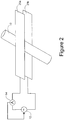
- each of the heating plates 6a, 6b includes a respective electrode 25a, 25b for causing dielectric heating of the hair 10 (reference numeral 10 in Figure 2 being used to denote a bundle of hair rather than a single strand).
- a variable frequency alternating current source 12 is provided to drive the electrodes 25a, 25b.
- the alternating current applied to the electrodes 25a, 25b causes an alternating electric field to be produced in the vicinity of (e.g. between) the electrodes 25a, 25b. Energy from the alternating electric field is coupled to the hair 10, thereby causing heating of the hair.
- Maximum energy coupling occurs when the frequency of the alternating electric field matches the peak absorption frequency of the hair, and when there is impedance matching between the drive circuitry (i.e. the circuitry that supplies electrical energy to the electrodes 25a, 25b) and the electrodes/hair.
- the drive circuitry i.e. the circuitry that supplies electrical energy to the electrodes 25a, 25b
- the inventors have found that the output impedance of the drive circuitry should be relatively low, of the order of 1-10 ohms and preferably about 2 ohms.
- Typical frequencies of operation of the alternating current source 12 are in the range of 10 MHz to 100 MHz, although our experimental tests have shown that frequencies in the range of 20 MHz to 40 MHz are ideal. These frequencies are well suited for consumer products since they have limited wave propagation (unlike microwaves) and hence do not present a risk to health or undesirable EMC (electromagnetic compatibility) effects.
- the electrodes 25a, 25b may themselves form the respective plates 6a, 6b, or they may be incorporated within the plates 6a, 6b.
- each of the plates 6a, 6b may be formed of a conductive material (e.g. aluminium), such that the plates 6a, 6b themselves act as the electrodes 25a, 25b.
- a conductive material e.g. aluminium
- the outer surface of each of the plates i.e. the opposing surfaces of the plates 6a, 6b, against which the hair comes into contact
- the non-conductive material may be a plastics material.
- aluminium is used to form the electrodes, then a non-conductive coating can be created on the aluminium by anodising.
- each of the plates 6a, 6b may be formed of a non-conductive material carrying a planar conductor as the respective electrode 25a, 25b.
- the plates 6a, 6b may be formed of a ceramic with a copper clad backing, or plastic with insert moulded metal. Again, to prevent a short circuit from occurring during use, the plates 6a, 6b are configured such that the electrodes 25a, 25b cannot come into direct contact with one another when the plates 6a, 6b are brought together.
- the opposing surfaces of the electrodes 25a, 25b may be coated in a plastics material.
- the arms 4a, 4b and/or plates 6a, 6b which support the electrodes 25a, 25b may also be formed from a plastics material, since high thermal resistance is not a requirement.
- the plates 6a, 6b typically only heat up to a temperature of about 70°C when heating hair.
- water is not evaporated when using the present method, and hence it is likely to require less energy than conventional styling techniques.
- the styler 1 can be made using lower temperature materials than those used to make conventional stylers that employ resistive heating.
- Such lower temperature materials e.g. plastics
- metals to obtain and form are typically less expensive than metals to obtain and form.
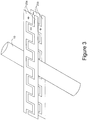
- each electrode 25a, 25b may include alternating interdigitated conductive regions of "positive” electrode and "negative” electrode, the interdigitated regions being arranged such that when the plates 6a, 6b are bought together, a "positive" electrode region of the first plate 6a opposes a "negative” electrode region of the second plate 6b, and a "negative” electrode region of the first plate 6a opposes a "positive” electrode region of the second plate 6b (as denoted by the "+” and "-” symbols in Figure 3 ).
- each electrode 25a, 25b is merely to enable the constituent regions of each electrode 25a, 25b to be distinguished from one another; in practice the constituent regions will both be subjected to an alternating current, with the constituent regions being driven out of phase with one another.
- the use of interdigitated electrodes in this manner helps to "focus" the electric field onto the hair, providing enhanced coupling of the energy into the hair, reducing stray field lines, and also reducing potential radiofrequency emissions.
- the interdigitated "fingers" of the "positive” and “negative” electrode regions may be much narrower than is illustrated, such that a plurality of interdigitated fingers span the width of a typical bundle of hair 10.
- the interdigitated fingers may be wider, e.g. as illustrated or wider still.
- the extent to which the interdigitated fingers pass alongside one another may be less than, or greater than, that as illustrated.
- the styler 1 is provided with electrical circuitry configured to provide feedback control to the variable frequency alternating current source 12, such that the frequency of the alternating current is tuned to the peak absorption frequency of the hair as it changes during the heating process.
- the feedback control provides means for varying the frequency of the alternating current supplied by the alternating current source 12, for determining which frequency of the supplied alternating current provides good coupling (preferably maximum coupling) of the alternating electric field (as produced in the vicinity of the electrodes 25a, 25b) to the hair, and for adjusting the frequency of the alternating current supplied by the alternating current source 12 so as to be at or around the determined frequency.
- the feedback control causes the frequency of the alternating current to be repeatedly tuned (or retuned) to the peak absorption frequency of the hair.
- the feedback control is performed by current sensing means 14 (e.g. an ammeter or other means for measuring current) arranged to sense the current being drawn from the drive circuitry by the electrodes 25a, 25b.
- a feedback signal from the current sensing means 14, representative of the magnitude of the current being drawn from the drive circuitry, is used to control the alternating current source 12.
- the feedback control operates on the principle that, when the frequency of the alternating current provided by the variable frequency alternating current source 12 is tuned to the peak absorption frequency of the hair 10, such that the alternating electric field (as produced in the vicinity of the electrodes 25a, 25b) couples well to the hair, the magnitude of the current drawn from the drive circuitry by the electrodes 25a, 25b will be significantly greater than when the frequency of the alternating current is not tuned to the peak absorption frequency of the hair and coupling is not occurring or is not occurring to the same extent.
- the magnitude of the current drawn from the drive circuitry during coupling may be around 2A whereas when the alternating current is not tuned to the peak absorption frequency of the hair, the current drawn may fall to around 20mA.
- the output from the current sensing means 14, as fed back to the current source 12, is used to control the frequency of the alternating current produced by the current source 12, and thereby tune the frequency of the alternating current to the peak absorption frequency of the hair 10.
- the frequency of the alternating current is tuned to the peak absorption frequency of the hair (as at that point in time) energy from the alternating electric field (as produced in the vicinity of the electrodes 25a, 25b) is coupled to the hair 10.
- circuitry shown in Figure 2 is somewhat simplified, in order to illustrate the principle of tuning the frequency of the alternating current that is applied to the electrodes, to achieve coupling of the alternating electric field with the hair.
- FIG. 4 illustrates in more detail electrical circuitry 20 suitable for use in the above embodiment of the styler 1.
- the electrical circuitry 20 includes a user interface 21, microprocessor 22, FET (field effect transistor) signal generator 23, drive circuitry 24, power supply 26, current sensing circuitry 27, and the above-described electrodes 25.
- microprocessor 22 includes a user interface 21, microprocessor 22, FET (field effect transistor) signal generator 23, drive circuitry 24, power supply 26, current sensing circuitry 27, and the above-described electrodes 25.
- FET field effect transistor
- the user interface 21 is as described above in relation to Figure 1 , and typically includes a switch 3 to enable the styler 1 to be turned on or off, and indicator means such as light 5 to indicate whether the power is on and whether the styler is ready to use.
- the microprocessor 22 is programmed and configured to control the operation of the styler 1, including the tuning of the frequency of the applied alternating current to the peak absorption frequency of the hair.
- the FET signal generator 23 is configured to receive electrical power from the power supply 26 and to provide an alternating voltage having a set frequency to the drive circuitry 24.
- the frequency of the alternating voltage provided by the FET signal generator 23 is controlled (or set) by the microprocessor 22.
- the power supply 26 is a mains power supply, in which case the FET signal generator 23 is configured to down-convert the mains AC electricity from around 230-240V to around 50V AC, e.g. using a switch mode system as will be familiar to those skilled in the art.
- the power supply 26 comprises one or more DC batteries or cells (which may be rechargeable, e.g. from the mains via a charging lead). This enables the styler 1 to be a cordless product.
- the FET signal generator 23 is configured to up-convert the DC voltage from the batteries/cells to around 50V AC.
- the drive circuitry 24 is configured to receive the alternating voltage from the FET signal generator 23 and to apply it across the electrodes 25 of the plates 6a, 6b. This causes a corresponding AC current to flow from the drive circuitry 24 into the electrodes 25.
- the drive circuitry 24 includes a switch that is activated (e.g. closed) when the arms 4a, 4b have been brought together and the plates 6a, 6b are closed.
- the drive circuitry 24 is configured to only apply energy to the electrodes 25 when the plates 6a, 6b are closed and the switch has been activated, thus providing a safety feature to the styler 1.
- other detection means may be used instead of a switch for this purpose, such as an optical interlock arrangement, or electrical contacts that come together when the plates 6a, 6b are closed.
- Current sensing circuitry 27 is coupled to the drive circuitry 24 (e.g. to an output of the drive circuitry 24), and is configured to sense the current output from the drive circuitry 24 and applied to the electrodes 25. An output signal from the current sensing circuitry 27, representative of the magnitude of this current, is fed back to the microprocessor 22. As discussed in relation to Figure 2 above, when the frequency of the alternating current is tuned to the peak absorption frequency of the hair, the magnitude of the current being drawn from the drive circuitry 24 by the electrodes 25 will be significantly greater than when the frequency of the alternating current is not tuned to the peak absorption frequency of the hair.
- the output from the current sensing means 14, as fed back to the microprocessor 22, is used by the microprocessor 22 to control the frequency of the alternating voltage produced by the FET signal generator 23, and thereby tune the frequency of the alternating current to the peak absorption frequency of the hair 10.
- the frequency and size of the absorption peak of the hair varies with the dampness of the hair, and also with the packing density of the hair.
- the absorption frequency is tracked throughout the styling process to ensure optimal coupling of energy into the hair during the styling process. This can be achieved in a number of ways:
- the current used to drive the electrodes, to cause an alternating electric field to be produced in the vicinity of the electrodes is supplied by a variable frequency alternating current source 12 or a variable frequency alternating voltage source such as FET signal generator 23.
- a DC source can be used, together with switching circuitry that repeatedly reverses the polarity of voltage/current applied to each of the electrodes, thereby causing an alternating electric field to be produced in the vicinity of the electrodes.
- Switches 34 and 35 are each reversibly switchable between a terminal A and a terminal B, under the control of switch controller 36, and in synchronicity with one another. Terminal A of switch 34 and terminal B of switch 35 are both connected to electrode 25a, whereas terminal B of switch 34 and terminal A of switch 35 are both connected to electrode 25b.
- electrode 25a is connected to the positive terminal of the DC voltage source 32
- electrode 25b is connected to the negative terminal of the DC voltage source.
- electrode 25a is connected to the negative terminal of the DC voltage source 32
- electrode 25b is connected to the positive terminal of the DC voltage source.
- the polarity of the voltage applied to each of the electrodes 25a, 25b can be repeatedly reversed, in order to cause an alternating electric field to be produced in the vicinity of the electrodes 25a, 25b.
- the timing of the switching events for the main drive signal is controlled by the microprocessor 22 as before.
- a wide band test signal is to be applied (for tracking the best drive frequency to use), then the timing of the switching events can be determined, for example, by a PN (pseudo noise) code generator 38, which is configured to supply a PN code to the switch controller 36.
- a PN pseudo noise
- an impulse generator 39 may be provided to control the position of the switches 34, 35. In this case, an impulse generated by the impulse generator 39 causes the switch controller 36 to quickly change the positions of the switches 34 and 35 to cause a short burst of alternating voltage to be applied to the electrodes 25. By analysing the current drawn by the electrodes 25 as a result of this short burst, the system can determine the optimum frequency at which to drive the electrodes for maximum energy coupling into the hair.
- the frequency of the supplied alternating current which causes the best energy coupling of the alternating electric field to the hair is determined.
- the analysis to make this determination can be performed in the time domain or in the frequency domain. In embodiments that sense the magnitude of multiple frequencies applied at the same time, this analysis is preferably done using frequency domain techniques (rather than trying to use time domain filtering techniques to separate the different frequency components).
- a frequency domain analyser may be provided, to analyse the frequencies present in the wideband current applied to the electrodes 25.
- the applied current may be analysed in the frequency domain by a frequency domain analyser (e.g. a processor running a Fast Fourier Transform (FFT) algorithm).
- the frequency domain analyser is configured to determine, via frequency analysis, the frequency of the current component that has the largest amplitude. That frequency (or a nearby frequency) is then identified as the frequency at which the electrodes 25 are then to be driven, and the drive frequency of the main drive signal is adjusted accordingly.
- sensing circuitry which comprises means for determining a frequency of the electrical energy at which better coupling of the alternating electric field to the hair takes place than with other frequencies; and the control circuitry is configured to control the drive circuitry to adjust the frequency of the electrical energy so as to be at or around the determined frequency.
- hair styling appliances including, but not limited to, a hair straightener, a hair crimping device, and a hair curler.
Landscapes
- Physics & Mathematics (AREA)
- Electromagnetism (AREA)
- Thermal Sciences (AREA)
- Control Of Resistance Heating (AREA)
- Hair Curling (AREA)
- Cleaning And Drying Hair (AREA)
Claims (15)
- Appareil de coiffure (1), comprenant :des premier et second bras (4a, 4b) qui peuvent se rapprocher et s'éloigner l'un de l'autre ;des première et seconde électrodes (25a, 25b) situées respectivement sur les premier et second bras (4a, 4b), de sorte que les électrodes (25a, 25b) soient opposées l'une à l'autre ;une circuiterie de commande (24) pour fournir de l'énergie électrique aux première et seconde électrodes (25a, 25b), pour provoquer la production d'un champ électrique alternatif au voisinage des électrodes (25a, 25b) lors de l'utilisation et provoquer ainsi un chauffage diélectrique des cheveux placés entre les électrodes (25a, 25b) lors de l'utilisation ;l'appareil de coiffure (1) étant caractérisé en ce qu'il comprend une circuiterie de détection (27) pour détecter une variation du couplage d'énergie du champ électrique alternatif aux cheveux pendant le chauffage des cheveux ; etune circuiterie de contrôle pour contrôler la circuiterie de commande (24) pour faire varier l'énergie électrique fournie aux première et seconde électrodes (25a, 25b) pendant le chauffage des cheveux en fonction de la variation de couplage détectée.
- Appareil selon la revendication 1, dans lequel la circuiterie de détection comprend en outre un moyen permettant de déterminer une fréquence de l'énergie électrique à laquelle un couplage qui se produit du champ électrique alternatif aux cheveux est meilleur qu'à d'autres fréquences ;
et dans lequel la circuiterie de contrôle est en outre configurée pour contrôler la circuiterie de commande pour régler la fréquence de l'énergie électrique afin qu'elle soit égale ou pratiquement égale à la fréquence déterminée. - Appareil selon la revendication 2, dans lequel le moyen de détermination comprend un moyen permettant de détecter le courant prélevé par les électrodes selon la fréquence de l'énergie électrique fournie et dans lequel la fréquence déterminée est la fréquence de l'énergie électrique fournie à laquelle la grandeur du courant détecté est sensiblement au niveau d'un pic.
- Appareil selon la revendication 3, dans lequel le moyen permettant de détecter le courant prélevé par les électrodes est configuré pour générer un signal de retour représentatif de la grandeur du courant prélevé par les électrodes ;
dans lequel la circuiterie de contrôle est configurée pour amener la circuiterie de commande à faire varier la fréquence de l'énergie électrique de manière à fournir des signaux de test aux électrodes à une pluralité de fréquences différentes sur une plage de fréquences ;
dans lequel la circuiterie de contrôle est configurée pour recevoir ledit signal de retour par rapport à chaque fréquence de la pluralité de fréquences et déterminer ainsi la fréquence de l'énergie électrique à laquelle un pic est obtenu dans le courant détecté ; et
dans lequel la circuiterie de contrôle est configurée pour amener la circuiterie de commande à fournir l'énergie électrique à une fréquence égale ou pratiquement égale à la fréquence déterminée pendant une période de temps ; et de préférence
dans lequel la circuiterie de contrôle est configurée pour amener la circuiterie de commande à générer le ou les signaux de test comprenant les différentes composantes de fréquence tout en fournissant sensiblement simultanément une énergie électrique aux électrodes à la fréquence déterminée pour provoquer le chauffage des cheveux ; et de préférence
dans lequel le ou les signaux de test sont à une faible amplitude par rapport à l'énergie électrique fournie à la fréquence déterminée. - Appareil selon la revendication 1, dans lequel la circuiterie de contrôle est configurée pour faire varier la fréquence de l'énergie électrique fournie aux première et seconde électrodes pendant le chauffage des cheveux.
- Appareil selon la revendication 5, dans lequel la circuiterie de contrôle est configurée pour faire varier la fréquence de l'énergie électrique au moyen d'une technique de saut de fréquence sur une plage de fréquences ou par balayage de fréquences sur une plage de fréquences ; ou en appliquant simultanément aux électrodes un signal de test comprenant une pluralité de fréquences.
- Appareil selon l'une quelconque des revendications précédentes, comprenant en outre un moyen permettant de détecter si les premier et second bras sont rapprochés et un moyen permettant de couper la fourniture d'énergie électrique aux électrodes si les premier et second bras ne sont pas détectés comme étant rapprochés.
- Appareil selon l'une quelconque des revendications précédentes, dans lequel :chacune des électrodes comprend une première région conductrice entrecroisée avec une seconde région conductrice ;la première région conductrice de la première électrode s'oppose à la première région conductrice de la seconde électrode ;la seconde région conductrice de la première électrode s'oppose à la seconde région conductrice de la seconde électrode ; etle circuit de commande est configuré pour commander les première et seconde régions conductrices de chaque électrode avec des signaux de commande qui sont sensiblement déphasés de 180 degrés entre eux.
- Procédé de coiffure au moyen d'un chauffage diélectrique, le procédé consistant à :placer des cheveux entre des première et seconde électrodes (25a, 25b) situées sur des premier et second bras (4a, 4b) respectifs d'un appareil de coiffure, les électrodes (25a, 25b) étant opposées l'une de l'autre et les premier et second bras (4a, 4b) pouvant se rapprocher et s'éloigner l'un de l'autre ;fournir de l'énergie électrique aux première et seconde électrodes (25a, 25b), pour provoquer la production d'un champ électrique alternatif au voisinage des électrodes (25a, 25b) et provoquer ainsi un chauffage diélectrique des cheveux ;le procédé étant caractérisé en ce qu'il consiste à détecter une variation du couplage d'énergie du champ électrique alternatif aux cheveux pendant le chauffage des cheveux ; etfaire varier l'énergie électrique fournie aux première et seconde électrodes (25a, 25b) pendant le chauffage des cheveux en fonction de la variation de couplage détectée.
- Procédé selon la revendication 9, consistant à faire varier la fréquence de l'énergie électrique fournie aux première et seconde électrodes pendant le chauffage des cheveux.
- Procédé selon la revendication 9, consistant en outre à :déterminer la fréquence de l'énergie électrique à laquelle un couplage se produit du champ électrique alternatif aux cheveux ; etrégler la fréquence de l'énergie électrique afin qu'elle soit égale à la fréquence déterminée.
- Procédé selon la revendication 11, dans lequel la détermination consiste à détecter le courant prélevé par les électrodes selon la fréquence de l'énergie électrique fournie et dans lequel la fréquence déterminée est la fréquence de l'énergie électrique fournie à laquelle la grandeur du courant détecté est sensiblement au niveau d'un pic ; et de préférence
dans lequel la détection du courant prélevé par les électrodes consiste à générer un signal de retour représentatif de la grandeur du courant prélevé par les électrodes ;
et le procédé consistant en outre à :faire varier la fréquence de l'énergie électrique de manière à fournir des signaux de test aux électrodes à une pluralité de fréquences différentes sur une plage de fréquences ;recevoir ledit signal de retour par rapport à chaque fréquence de la pluralité de fréquences et déterminer ainsi la fréquence du courant alternatif à laquelle un pic est obtenu dans le courant détecté ; puisfournir l'énergie électrique à la fréquence déterminée pendant une période de temps ; et de préférencedans lequel la fréquence de l'énergie électrique est variée au moyen d'un saut de fréquence sur la plage de fréquences ou dans lequel la fréquence de l'énergie électrique est variée par balayage de fréquences sur la plage de fréquences. - Procédé selon la revendication 12, le procédé consistant en outre à :déclencher un signal de test à large bande comprenant une pluralité simultanée de signaux constituants à différentes fréquences dans une plage de fréquences ;déterminer, par l'intermédiaire d'une analyse de fréquence, la fréquence d'un signal constituant qui a été soustrait du signal à large bande à la suite du couplage, provoqué par ce signal de fréquence, du champ électrique alternatif aux cheveux ; etfournir l'énergie électrique à la fréquence déterminée pendant une période de temps.
- Procédé de selon l'une quelconque des revendications 9 à 13, consistant en outre à détecter si les premier et second bras sont rapprochés et à couper la fourniture d'énergie électrique aux électrodes si les premier et second bras ne sont pas détectés comme étant rapprochés.
- Procédé selon l'une quelconque des revendications 9 à 14, dans lequel chacune des électrodes comprend une première région entrecroisée avec une seconde région ;
la première région de la première électrode s'oppose à la première région de la seconde électrode ;
la seconde région de la première électrode s'oppose à la seconde région de la seconde électrode ; et
les première et seconde régions de chaque électrode sont commandées en déphase entre elles.
Applications Claiming Priority (2)
| Application Number | Priority Date | Filing Date | Title |
|---|---|---|---|
| GB1423039.5A GB2533602B (en) | 2014-12-23 | 2014-12-23 | Method and apparatus for manipulating the shape of hair |
| PCT/GB2015/054154 WO2016102972A2 (fr) | 2014-12-23 | 2015-12-23 | Procédé et appareil de manipulation de la forme des cheveux |
Publications (2)
| Publication Number | Publication Date |
|---|---|
| EP3236797A2 EP3236797A2 (fr) | 2017-11-01 |
| EP3236797B1 true EP3236797B1 (fr) | 2020-12-16 |
Family
ID=55135450
Family Applications (1)
| Application Number | Title | Priority Date | Filing Date |
|---|---|---|---|
| EP15823741.2A Active EP3236797B1 (fr) | 2014-12-23 | 2015-12-23 | Procédé et appareil de manipulation de la forme des cheveux |
Country Status (7)
| Country | Link |
|---|---|
| US (2) | US10716381B2 (fr) |
| EP (1) | EP3236797B1 (fr) |
| CN (1) | CN107105850B (fr) |
| AU (1) | AU2015370686B2 (fr) |
| ES (1) | ES2843951T3 (fr) |
| GB (1) | GB2533602B (fr) |
| WO (1) | WO2016102972A2 (fr) |
Families Citing this family (29)
| Publication number | Priority date | Publication date | Assignee | Title |
|---|---|---|---|---|
| GB2533602B (en) | 2014-12-23 | 2020-11-11 | Jemella Ltd | Method and apparatus for manipulating the shape of hair |
| DE102016107550B4 (de) * | 2016-04-22 | 2021-09-16 | Helmholtz-Zentrum Für Umweltforschung Gmbh - Ufz | Verfahren und Vorrichtung zur thermischen Behandlung von Feststoffen |
| GB2569655B (en) | 2017-12-22 | 2022-05-11 | Jemella Ltd | Training system and device |
| EP3643196A1 (fr) * | 2018-10-25 | 2020-04-29 | Koninklijke Philips N.V. | Coiffage utilisant un chauffage diélectrique |
| USD921983S1 (en) * | 2019-03-19 | 2021-06-08 | Guangdong Huanengda Electrical Appliances Co., Ltd. | Hair styling tool |
| USD919177S1 (en) * | 2019-09-30 | 2021-05-11 | Dongguan Empress Technology Co., Ltd. | Hair wave curler |
| GB2597684B (en) * | 2020-07-29 | 2022-09-07 | Dyson Technology Ltd | Hairstyling device |
| GB2597683B (en) * | 2020-07-29 | 2022-11-23 | Dyson Technology Ltd | Hairstyling device |
| GB2597677A (en) * | 2020-07-29 | 2022-02-09 | Dyson Technology Ltd | Hairstyling device |
| GB2597679B (en) * | 2020-07-29 | 2022-09-07 | Dyson Technology Ltd | Hairstyling device |
| GB2597680B (en) | 2020-07-29 | 2022-12-28 | Dyson Technology Ltd | Hairstyling device |
| GB2597688B (en) | 2020-07-29 | 2022-09-21 | Dyson Technology Ltd | Hairstyling device |
| GB2597678B (en) * | 2020-07-29 | 2022-11-30 | Dyson Technology Ltd | Hairstyling device |
| GB2597681B (en) * | 2020-07-29 | 2022-11-30 | Dyson Technology Ltd | Hairstyling device |
| GB2607068B (en) * | 2021-05-27 | 2023-06-28 | Dyson Technology Ltd | A hair styling appliance |
| GB2607066B (en) * | 2021-05-27 | 2024-09-04 | Dyson Technology Ltd | A hair styling appliance |
| GB2607065B (en) * | 2021-05-27 | 2024-09-04 | Dyson Technology Ltd | A hair styling appliance |
| GB2607064B (en) * | 2021-05-27 | 2025-02-12 | Dyson Technology Ltd | A hair styling appliance |
| GB2607062B (en) * | 2021-05-27 | 2024-10-09 | Dyson Technology Ltd | A hair styling appliance |
| GB2607069B (en) * | 2021-05-27 | 2023-11-29 | Dyson Technology Ltd | A hair styling appliance |
| GB2607071B (en) * | 2021-05-27 | 2024-09-04 | Dyson Technology Ltd | A hair styling appliance |
| GB2607063B (en) | 2021-05-27 | 2023-09-06 | Dyson Technology Ltd | Power inverter |
| GB2607067B (en) * | 2021-05-27 | 2024-08-28 | Dyson Technology Ltd | A hair styling appliance |
| GB2619933B (en) * | 2022-06-21 | 2024-08-21 | Dyson Technology Ltd | A hair styling appliance |
| GB2619932B (en) * | 2022-06-21 | 2024-08-21 | Dyson Technology Ltd | A hair styling appliance |
| GB2624882A (en) * | 2022-11-29 | 2024-06-05 | Dyson Technology Ltd | A hair styling appliance |
| USD1006323S1 (en) * | 2023-03-09 | 2023-11-28 | Jinwang Liao | Hair straightener |
| USD1064406S1 (en) * | 2024-01-17 | 2025-02-25 | Gamma Piu' S.R.L. | Hair straightening iron |
| CN118748855A (zh) * | 2024-07-15 | 2024-10-08 | 东莞市乐美智能科技有限公司 | 一种新工艺mch发热器及控制电路 |
Family Cites Families (30)
| Publication number | Priority date | Publication date | Assignee | Title |
|---|---|---|---|---|
| GB589911A (en) * | 1945-08-14 | 1947-07-03 | Ace Electronics Ltd | Improvements in and relating to the electric treatment of hair |
| US2892915A (en) * | 1957-06-19 | 1959-06-30 | Armstrong Cork Co | Dielectric heater electrode systems |
| DE7800655U1 (de) | 1978-01-11 | 1979-11-15 | Dokoupil, Jiri, Dipl.-Ing., 6251 Gueckingen | Industriedampfbügeleisen mit elektrisch beheizter und geregelter Sohle |
| GB1601713A (en) * | 1978-02-07 | 1981-11-04 | Electronic Kilns Luzern Gmbh | Drying lumber |
| US4242567A (en) * | 1978-06-05 | 1980-12-30 | General Electric Company | Electrically heated hair straightener and PTC heater assembly therefor |
| DE3115569A1 (de) | 1981-04-16 | 1982-12-09 | Cooper Industries, Inc., 77210 Houston, Tex. | "elektrisch beheiztes loetwerkzeug" |
| US4531038A (en) * | 1984-06-11 | 1985-07-23 | Champion International Corporation | Radio frequency dielectric heater |
| GB2163574A (en) | 1984-08-24 | 1986-02-26 | Thorn Emi Domestic Appliances | Domestic electrical appliances |
| JPS63161902A (ja) * | 1986-12-26 | 1988-07-05 | 瀧前 豊作 | 縮毛矯正用アイロン |
| JP2554733B2 (ja) * | 1989-01-20 | 1996-11-13 | 積水化学工業株式会社 | 樹脂チューブの接合方法 |
| JPH06123062A (ja) * | 1992-10-13 | 1994-05-06 | Ii C Kagaku Kk | 獣毛の改質法 |
| GB9619579D0 (en) | 1996-09-19 | 1996-10-30 | Deveney John | Seaming iron |
| US6657173B2 (en) * | 1998-04-21 | 2003-12-02 | State Board Of Higher Education On Behalf Of Oregon State University | Variable frequency automated capacitive radio frequency (RF) dielectric heating system |
| KR200284378Y1 (ko) * | 2002-03-08 | 2002-08-10 | 박강수 | 가열된 유체를 열원으로 하는 고데기 |
| MXPA04012531A (es) | 2002-06-26 | 2005-11-04 | Procter & Gamble | Dispositivo que suaviza y alisa el cabello. |
| US7586066B2 (en) * | 2004-11-22 | 2009-09-08 | Chris Baldwin Bell | Hair styling device and method |
| BRPI0713515A2 (pt) * | 2006-06-30 | 2012-02-07 | Procter & Gamble | dispositivo para medição de umidade em substrato e saúde capilar |
| KR100966798B1 (ko) | 2008-05-15 | 2010-06-29 | (주)언일전자 | 헤어 아이론 |
| EP2467701B1 (fr) | 2009-08-17 | 2021-10-06 | Malvern Panalytical Limited | Microrhéologie basée sur la diffusion dynamique de la lumière de fluides complexes, avec détection en mode diffusion simple améliorée |
| DE102009045498B4 (de) * | 2009-10-08 | 2015-12-24 | Hochschule für angewandte Wissenschaft und Kunst Fachhochschule Hildesheim/Holzminden/Göttingen | Verfahren und Vorrichtung zum Abtöten von Parasiten und deren Vorformen an filamentösem Gut |
| KR101821837B1 (ko) * | 2010-04-08 | 2018-01-24 | 액세스 비지니스 그룹 인터내셔날 엘엘씨 | Pos 유도성 시스템 및 방법 |
| FR2959917B1 (fr) * | 2010-05-11 | 2012-07-27 | Oreal | Procede de traitement des cheveux |
| DE102011010273A1 (de) * | 2011-02-02 | 2012-08-02 | Cinogy Gmbh | Verfahren zur Behandlung von menschlichem oder tierischem Haar und Gerät zur Durchführung des Verfahrens |
| US20120312319A1 (en) * | 2011-06-09 | 2012-12-13 | Izumi Uwano | Vibrating Hair Iron With Noncontact Switch |
| JP2013244037A (ja) | 2012-05-23 | 2013-12-09 | Sharp Corp | アイロン及びアイロン台 |
| US9572412B2 (en) | 2012-06-07 | 2017-02-21 | L'oreal | Hair shaping process using fatty substances, non-silicone polymers or surfactants |
| GB2500733B (en) * | 2012-06-25 | 2014-05-21 | Jemella Ltd | Hair styling appliance |
| CN102917485A (zh) * | 2012-09-28 | 2013-02-06 | 深圳华路仕科技有限公司 | 一种卷发器加热装置 |
| GB201401146D0 (en) * | 2014-01-23 | 2014-03-12 | Linde Ag | Non-thermal plasma |
| GB2533602B (en) | 2014-12-23 | 2020-11-11 | Jemella Ltd | Method and apparatus for manipulating the shape of hair |
-
2014
- 2014-12-23 GB GB1423039.5A patent/GB2533602B/en active Active
-
2015
- 2015-12-23 ES ES15823741T patent/ES2843951T3/es active Active
- 2015-12-23 EP EP15823741.2A patent/EP3236797B1/fr active Active
- 2015-12-23 AU AU2015370686A patent/AU2015370686B2/en active Active
- 2015-12-23 US US15/539,616 patent/US10716381B2/en active Active
- 2015-12-23 WO PCT/GB2015/054154 patent/WO2016102972A2/fr not_active Ceased
- 2015-12-23 CN CN201580069699.XA patent/CN107105850B/zh active Active
-
2020
- 2020-06-10 US US16/897,773 patent/US11771192B2/en active Active
Non-Patent Citations (1)
| Title |
|---|
| None * |
Also Published As
| Publication number | Publication date |
|---|---|
| AU2015370686A1 (en) | 2017-06-22 |
| GB2533602A (en) | 2016-06-29 |
| AU2015370686B2 (en) | 2020-05-21 |
| WO2016102972A2 (fr) | 2016-06-30 |
| US20170360174A1 (en) | 2017-12-21 |
| US20200297091A1 (en) | 2020-09-24 |
| CN107105850A (zh) | 2017-08-29 |
| CN107105850B (zh) | 2021-03-16 |
| WO2016102972A3 (fr) | 2016-09-15 |
| US11771192B2 (en) | 2023-10-03 |
| EP3236797A2 (fr) | 2017-11-01 |
| US10716381B2 (en) | 2020-07-21 |
| GB2533602B (en) | 2020-11-11 |
| ES2843951T3 (es) | 2021-07-21 |
Similar Documents
| Publication | Publication Date | Title |
|---|---|---|
| US11771192B2 (en) | Method and apparatus for manipulating the shape of hair | |
| EP3416521B1 (fr) | Séchage et coiffure des cheveux par ultrasons | |
| CN102170834B (zh) | 电手术装置和高频处置装置 | |
| EP1511993A1 (fr) | Capteur a coupleur directionnel pour la mesure de l'humidite des cheveux | |
| US20170164974A1 (en) | Ultrasonic treatment apparatus | |
| US20250134227A1 (en) | Hair styling device | |
| US20250057580A1 (en) | Electrosurgical system for use with non-stick coated electrodes | |
| CN117397366A (zh) | 一种头发造型器具 | |
| CN111024254B (zh) | 加热装置以及用于加热装置处的温度检测的方法 | |
| CN117356168A (zh) | 一种头发造型器具 | |
| US11369427B2 (en) | System and method of manufacturing non-stick coated electrodes | |
| MXPA06012444A (es) | Sensor de humedad en circuito lc con factor q alto. | |
| RU2776747C1 (ru) | Укладка волос с использованием диэлектрического нагрева | |
| US20210393012A1 (en) | Hair styling using dielectric heating | |
| KR102134684B1 (ko) | 라디오파 가열 조리기기 | |
| WO2024099881A1 (fr) | Commande de dispositif de soins personnels basée sur le taux d'hydratation de la peau | |
| GB2644318A (en) | Heater apparatus for a hair styling appliance and methods of control | |
| US8721635B2 (en) | Bipolar chondroplasty device | |
| Li et al. | Monitoring of coagulation degree of soymilk by electrical impedance spectroscopy and ohmic heating |
Legal Events
| Date | Code | Title | Description |
|---|---|---|---|
| STAA | Information on the status of an ep patent application or granted ep patent |
Free format text: STATUS: THE INTERNATIONAL PUBLICATION HAS BEEN MADE |
|
| PUAI | Public reference made under article 153(3) epc to a published international application that has entered the european phase |
Free format text: ORIGINAL CODE: 0009012 |
|
| STAA | Information on the status of an ep patent application or granted ep patent |
Free format text: STATUS: REQUEST FOR EXAMINATION WAS MADE |
|
| 17P | Request for examination filed |
Effective date: 20170721 |
|
| AK | Designated contracting states |
Kind code of ref document: A2 Designated state(s): AL AT BE BG CH CY CZ DE DK EE ES FI FR GB GR HR HU IE IS IT LI LT LU LV MC MK MT NL NO PL PT RO RS SE SI SK SM TR |
|
| AX | Request for extension of the european patent |
Extension state: BA ME |
|
| DAV | Request for validation of the european patent (deleted) | ||
| DAX | Request for extension of the european patent (deleted) | ||
| STAA | Information on the status of an ep patent application or granted ep patent |
Free format text: STATUS: EXAMINATION IS IN PROGRESS |
|
| 17Q | First examination report despatched |
Effective date: 20191008 |
|
| GRAP | Despatch of communication of intention to grant a patent |
Free format text: ORIGINAL CODE: EPIDOSNIGR1 |
|
| STAA | Information on the status of an ep patent application or granted ep patent |
Free format text: STATUS: GRANT OF PATENT IS INTENDED |
|
| INTG | Intention to grant announced |
Effective date: 20200710 |
|
| GRAS | Grant fee paid |
Free format text: ORIGINAL CODE: EPIDOSNIGR3 |
|
| GRAA | (expected) grant |
Free format text: ORIGINAL CODE: 0009210 |
|
| STAA | Information on the status of an ep patent application or granted ep patent |
Free format text: STATUS: THE PATENT HAS BEEN GRANTED |
|
| AK | Designated contracting states |
Kind code of ref document: B1 Designated state(s): AL AT BE BG CH CY CZ DE DK EE ES FI FR GB GR HR HU IE IS IT LI LT LU LV MC MK MT NL NO PL PT RO RS SE SI SK SM TR |
|
| REG | Reference to a national code |
Ref country code: GB Ref legal event code: FG4D |
|
| RIN1 | Information on inventor provided before grant (corrected) |
Inventor name: MOORE, TIMOTHY DAVID Inventor name: WILLIAMSON, ROGER JAMES |
|
| REG | Reference to a national code |
Ref country code: DE Ref legal event code: R096 Ref document number: 602015063636 Country of ref document: DE |
|
| REG | Reference to a national code |
Ref country code: IE Ref legal event code: FG4D |
|
| REG | Reference to a national code |
Ref country code: AT Ref legal event code: REF Ref document number: 1344777 Country of ref document: AT Kind code of ref document: T Effective date: 20210115 |
|
| REG | Reference to a national code |
Ref country code: DE Ref legal event code: R082 Ref document number: 602015063636 Country of ref document: DE Representative=s name: MATHYS & SQUIRE EUROPE PATENTANWAELTE PARTNERS, DE Ref country code: DE Ref legal event code: R082 Ref document number: 602015063636 Country of ref document: DE Representative=s name: MATHYS & SQUIRE GBR, DE |
|
| PG25 | Lapsed in a contracting state [announced via postgrant information from national office to epo] |
Ref country code: NO Free format text: LAPSE BECAUSE OF FAILURE TO SUBMIT A TRANSLATION OF THE DESCRIPTION OR TO PAY THE FEE WITHIN THE PRESCRIBED TIME-LIMIT Effective date: 20210316 Ref country code: RS Free format text: LAPSE BECAUSE OF FAILURE TO SUBMIT A TRANSLATION OF THE DESCRIPTION OR TO PAY THE FEE WITHIN THE PRESCRIBED TIME-LIMIT Effective date: 20201216 Ref country code: FI Free format text: LAPSE BECAUSE OF FAILURE TO SUBMIT A TRANSLATION OF THE DESCRIPTION OR TO PAY THE FEE WITHIN THE PRESCRIBED TIME-LIMIT Effective date: 20201216 Ref country code: GR Free format text: LAPSE BECAUSE OF FAILURE TO SUBMIT A TRANSLATION OF THE DESCRIPTION OR TO PAY THE FEE WITHIN THE PRESCRIBED TIME-LIMIT Effective date: 20210317 |
|
| REG | Reference to a national code |
Ref country code: AT Ref legal event code: MK05 Ref document number: 1344777 Country of ref document: AT Kind code of ref document: T Effective date: 20201216 |
|
| REG | Reference to a national code |
Ref country code: NL Ref legal event code: MP Effective date: 20201216 |
|
| PG25 | Lapsed in a contracting state [announced via postgrant information from national office to epo] |
Ref country code: LV Free format text: LAPSE BECAUSE OF FAILURE TO SUBMIT A TRANSLATION OF THE DESCRIPTION OR TO PAY THE FEE WITHIN THE PRESCRIBED TIME-LIMIT Effective date: 20201216 Ref country code: SE Free format text: LAPSE BECAUSE OF FAILURE TO SUBMIT A TRANSLATION OF THE DESCRIPTION OR TO PAY THE FEE WITHIN THE PRESCRIBED TIME-LIMIT Effective date: 20201216 Ref country code: BG Free format text: LAPSE BECAUSE OF FAILURE TO SUBMIT A TRANSLATION OF THE DESCRIPTION OR TO PAY THE FEE WITHIN THE PRESCRIBED TIME-LIMIT Effective date: 20210316 |
|
| PG25 | Lapsed in a contracting state [announced via postgrant information from national office to epo] |
Ref country code: NL Free format text: LAPSE BECAUSE OF FAILURE TO SUBMIT A TRANSLATION OF THE DESCRIPTION OR TO PAY THE FEE WITHIN THE PRESCRIBED TIME-LIMIT Effective date: 20201216 Ref country code: HR Free format text: LAPSE BECAUSE OF FAILURE TO SUBMIT A TRANSLATION OF THE DESCRIPTION OR TO PAY THE FEE WITHIN THE PRESCRIBED TIME-LIMIT Effective date: 20201216 |
|
| REG | Reference to a national code |
Ref country code: LT Ref legal event code: MG9D |
|
| REG | Reference to a national code |
Ref country code: ES Ref legal event code: FG2A Ref document number: 2843951 Country of ref document: ES Kind code of ref document: T3 Effective date: 20210721 |
|
| PG25 | Lapsed in a contracting state [announced via postgrant information from national office to epo] |
Ref country code: SK Free format text: LAPSE BECAUSE OF FAILURE TO SUBMIT A TRANSLATION OF THE DESCRIPTION OR TO PAY THE FEE WITHIN THE PRESCRIBED TIME-LIMIT Effective date: 20201216 Ref country code: PT Free format text: LAPSE BECAUSE OF FAILURE TO SUBMIT A TRANSLATION OF THE DESCRIPTION OR TO PAY THE FEE WITHIN THE PRESCRIBED TIME-LIMIT Effective date: 20210416 Ref country code: RO Free format text: LAPSE BECAUSE OF FAILURE TO SUBMIT A TRANSLATION OF THE DESCRIPTION OR TO PAY THE FEE WITHIN THE PRESCRIBED TIME-LIMIT Effective date: 20201216 Ref country code: LT Free format text: LAPSE BECAUSE OF FAILURE TO SUBMIT A TRANSLATION OF THE DESCRIPTION OR TO PAY THE FEE WITHIN THE PRESCRIBED TIME-LIMIT Effective date: 20201216 Ref country code: SM Free format text: LAPSE BECAUSE OF FAILURE TO SUBMIT A TRANSLATION OF THE DESCRIPTION OR TO PAY THE FEE WITHIN THE PRESCRIBED TIME-LIMIT Effective date: 20201216 Ref country code: EE Free format text: LAPSE BECAUSE OF FAILURE TO SUBMIT A TRANSLATION OF THE DESCRIPTION OR TO PAY THE FEE WITHIN THE PRESCRIBED TIME-LIMIT Effective date: 20201216 Ref country code: CZ Free format text: LAPSE BECAUSE OF FAILURE TO SUBMIT A TRANSLATION OF THE DESCRIPTION OR TO PAY THE FEE WITHIN THE PRESCRIBED TIME-LIMIT Effective date: 20201216 |
|
| REG | Reference to a national code |
Ref country code: CH Ref legal event code: PL |
|
| PG25 | Lapsed in a contracting state [announced via postgrant information from national office to epo] |
Ref country code: AT Free format text: LAPSE BECAUSE OF FAILURE TO SUBMIT A TRANSLATION OF THE DESCRIPTION OR TO PAY THE FEE WITHIN THE PRESCRIBED TIME-LIMIT Effective date: 20201216 Ref country code: PL Free format text: LAPSE BECAUSE OF FAILURE TO SUBMIT A TRANSLATION OF THE DESCRIPTION OR TO PAY THE FEE WITHIN THE PRESCRIBED TIME-LIMIT Effective date: 20201216 |
|
| REG | Reference to a national code |
Ref country code: BE Ref legal event code: MM Effective date: 20201231 |
|
| REG | Reference to a national code |
Ref country code: DE Ref legal event code: R097 Ref document number: 602015063636 Country of ref document: DE |
|
| PG25 | Lapsed in a contracting state [announced via postgrant information from national office to epo] |
Ref country code: IS Free format text: LAPSE BECAUSE OF FAILURE TO SUBMIT A TRANSLATION OF THE DESCRIPTION OR TO PAY THE FEE WITHIN THE PRESCRIBED TIME-LIMIT Effective date: 20210416 Ref country code: MC Free format text: LAPSE BECAUSE OF FAILURE TO SUBMIT A TRANSLATION OF THE DESCRIPTION OR TO PAY THE FEE WITHIN THE PRESCRIBED TIME-LIMIT Effective date: 20201216 |
|
| PLBE | No opposition filed within time limit |
Free format text: ORIGINAL CODE: 0009261 |
|
| STAA | Information on the status of an ep patent application or granted ep patent |
Free format text: STATUS: NO OPPOSITION FILED WITHIN TIME LIMIT |
|
| PG25 | Lapsed in a contracting state [announced via postgrant information from national office to epo] |
Ref country code: LU Free format text: LAPSE BECAUSE OF NON-PAYMENT OF DUE FEES Effective date: 20201223 Ref country code: AL Free format text: LAPSE BECAUSE OF FAILURE TO SUBMIT A TRANSLATION OF THE DESCRIPTION OR TO PAY THE FEE WITHIN THE PRESCRIBED TIME-LIMIT Effective date: 20201216 Ref country code: IE Free format text: LAPSE BECAUSE OF NON-PAYMENT OF DUE FEES Effective date: 20201223 |
|
| 26N | No opposition filed |
Effective date: 20210917 |
|
| PG25 | Lapsed in a contracting state [announced via postgrant information from national office to epo] |
Ref country code: DK Free format text: LAPSE BECAUSE OF FAILURE TO SUBMIT A TRANSLATION OF THE DESCRIPTION OR TO PAY THE FEE WITHIN THE PRESCRIBED TIME-LIMIT Effective date: 20201216 Ref country code: CH Free format text: LAPSE BECAUSE OF NON-PAYMENT OF DUE FEES Effective date: 20201231 Ref country code: LI Free format text: LAPSE BECAUSE OF NON-PAYMENT OF DUE FEES Effective date: 20201231 |
|
| PG25 | Lapsed in a contracting state [announced via postgrant information from national office to epo] |
Ref country code: SI Free format text: LAPSE BECAUSE OF FAILURE TO SUBMIT A TRANSLATION OF THE DESCRIPTION OR TO PAY THE FEE WITHIN THE PRESCRIBED TIME-LIMIT Effective date: 20201216 |
|
| PG25 | Lapsed in a contracting state [announced via postgrant information from national office to epo] |
Ref country code: IS Free format text: LAPSE BECAUSE OF FAILURE TO SUBMIT A TRANSLATION OF THE DESCRIPTION OR TO PAY THE FEE WITHIN THE PRESCRIBED TIME-LIMIT Effective date: 20210416 Ref country code: TR Free format text: LAPSE BECAUSE OF FAILURE TO SUBMIT A TRANSLATION OF THE DESCRIPTION OR TO PAY THE FEE WITHIN THE PRESCRIBED TIME-LIMIT Effective date: 20201216 Ref country code: MT Free format text: LAPSE BECAUSE OF FAILURE TO SUBMIT A TRANSLATION OF THE DESCRIPTION OR TO PAY THE FEE WITHIN THE PRESCRIBED TIME-LIMIT Effective date: 20201216 Ref country code: CY Free format text: LAPSE BECAUSE OF FAILURE TO SUBMIT A TRANSLATION OF THE DESCRIPTION OR TO PAY THE FEE WITHIN THE PRESCRIBED TIME-LIMIT Effective date: 20201216 |
|
| PG25 | Lapsed in a contracting state [announced via postgrant information from national office to epo] |
Ref country code: MK Free format text: LAPSE BECAUSE OF FAILURE TO SUBMIT A TRANSLATION OF THE DESCRIPTION OR TO PAY THE FEE WITHIN THE PRESCRIBED TIME-LIMIT Effective date: 20201216 |
|
| PG25 | Lapsed in a contracting state [announced via postgrant information from national office to epo] |
Ref country code: BE Free format text: LAPSE BECAUSE OF NON-PAYMENT OF DUE FEES Effective date: 20201231 |
|
| P01 | Opt-out of the competence of the unified patent court (upc) registered |
Effective date: 20230525 |
|
| PGFP | Annual fee paid to national office [announced via postgrant information from national office to epo] |
Ref country code: ES Payment date: 20250114 Year of fee payment: 10 |
|
| PGFP | Annual fee paid to national office [announced via postgrant information from national office to epo] |
Ref country code: DE Payment date: 20251218 Year of fee payment: 11 |
|
| PGFP | Annual fee paid to national office [announced via postgrant information from national office to epo] |
Ref country code: GB Payment date: 20251223 Year of fee payment: 11 |
|
| PGFP | Annual fee paid to national office [announced via postgrant information from national office to epo] |
Ref country code: FR Payment date: 20251223 Year of fee payment: 11 |
|
| PGFP | Annual fee paid to national office [announced via postgrant information from national office to epo] |
Ref country code: IT Payment date: 20251218 Year of fee payment: 11 |