EP3236879B1 - Verwendung eines cbct-knochenscans zum entwurf einer zahnstütze - Google Patents
Verwendung eines cbct-knochenscans zum entwurf einer zahnstütze Download PDFInfo
- Publication number
- EP3236879B1 EP3236879B1 EP15813452.8A EP15813452A EP3236879B1 EP 3236879 B1 EP3236879 B1 EP 3236879B1 EP 15813452 A EP15813452 A EP 15813452A EP 3236879 B1 EP3236879 B1 EP 3236879B1
- Authority
- EP
- European Patent Office
- Prior art keywords
- abutment
- digital
- design
- scan
- jawbone
- Prior art date
- Legal status (The legal status is an assumption and is not a legal conclusion. Google has not performed a legal analysis and makes no representation as to the accuracy of the status listed.)
- Active
Links
Images


Classifications
-
- A—HUMAN NECESSITIES
- A61—MEDICAL OR VETERINARY SCIENCE; HYGIENE
- A61B—DIAGNOSIS; SURGERY; IDENTIFICATION
- A61B6/00—Apparatus or devices for radiation diagnosis; Apparatus or devices for radiation diagnosis combined with radiation therapy equipment
- A61B6/02—Arrangements for diagnosis sequentially in different planes; Stereoscopic radiation diagnosis
- A61B6/03—Computed tomography [CT]
- A61B6/032—Transmission computed tomography [CT]
-
- A—HUMAN NECESSITIES
- A61—MEDICAL OR VETERINARY SCIENCE; HYGIENE
- A61B—DIAGNOSIS; SURGERY; IDENTIFICATION
- A61B6/00—Apparatus or devices for radiation diagnosis; Apparatus or devices for radiation diagnosis combined with radiation therapy equipment
- A61B6/40—Arrangements for generating radiation specially adapted for radiation diagnosis
- A61B6/4064—Arrangements for generating radiation specially adapted for radiation diagnosis specially adapted for producing a particular type of beam
- A61B6/4085—Cone-beams
-
- A—HUMAN NECESSITIES
- A61—MEDICAL OR VETERINARY SCIENCE; HYGIENE
- A61B—DIAGNOSIS; SURGERY; IDENTIFICATION
- A61B6/00—Apparatus or devices for radiation diagnosis; Apparatus or devices for radiation diagnosis combined with radiation therapy equipment
- A61B6/50—Apparatus or devices for radiation diagnosis; Apparatus or devices for radiation diagnosis combined with radiation therapy equipment specially adapted for specific body parts; specially adapted for specific clinical applications
- A61B6/51—Apparatus or devices for radiation diagnosis; Apparatus or devices for radiation diagnosis combined with radiation therapy equipment specially adapted for specific body parts; specially adapted for specific clinical applications for dentistry
-
- A—HUMAN NECESSITIES
- A61—MEDICAL OR VETERINARY SCIENCE; HYGIENE
- A61C—DENTISTRY; APPARATUS OR METHODS FOR ORAL OR DENTAL HYGIENE
- A61C13/00—Dental prostheses; Making same
- A61C13/0003—Making bridge-work, inlays, implants or the like
- A61C13/0004—Computer-assisted sizing or machining of dental prostheses
-
- A—HUMAN NECESSITIES
- A61—MEDICAL OR VETERINARY SCIENCE; HYGIENE
- A61C—DENTISTRY; APPARATUS OR METHODS FOR ORAL OR DENTAL HYGIENE
- A61C8/00—Means to be fixed to the jaw-bone for consolidating natural teeth or for fixing dental prostheses thereon; Dental implants; Implanting tools
- A61C8/0048—Connecting the upper structure to the implant, e.g. bridging bars
- A61C8/005—Connecting devices for joining an upper structure with an implant member, e.g. spacers
-
- A—HUMAN NECESSITIES
- A61—MEDICAL OR VETERINARY SCIENCE; HYGIENE
- A61C—DENTISTRY; APPARATUS OR METHODS FOR ORAL OR DENTAL HYGIENE
- A61C8/00—Means to be fixed to the jaw-bone for consolidating natural teeth or for fixing dental prostheses thereon; Dental implants; Implanting tools
- A61C8/008—Healing caps or the like
-
- G—PHYSICS
- G06—COMPUTING OR CALCULATING; COUNTING
- G06F—ELECTRIC DIGITAL DATA PROCESSING
- G06F30/00—Computer-aided design [CAD]
- G06F30/20—Design optimisation, verification or simulation
Definitions
- This invention generally relates to designing an implant abutment. More particularly, the invention relates to using a bone scan of a patient's jaw to design an abutment based on predetermined design criteria. Using the bone scan to constrain the design of the abutment while having a predetermined set of design criteria, will make it possible to design an abutment that will better fit a patient's specific situation.
- a screw retained restoration has a screw access hole in the occlusal side, through which it is possible to fasten the restoration in the implant using a matching screw.
- this method of attaching the restoration invariably means that the screw access hole has to be lined up perfectly with the direction of the implant borehole. In some situations, especially for anterior teeth, this arrangement will mean that the screw access hole would become an aesthetic liability.
- One way to ameliorate this problem is to use an implant abutment and a cemented restoration. It is known in the field to use a CBCT scan to determine the position and shape of a dental implant.
- US2010/0105009 describes a systematic approach to planning and selection of a dental implant, wherein models of the patient's dentition, including the gingival and supporting bone structure are analysed in relation to a model of the dentition that will be replaced by the implant.
- the invention relates to a method of generating a digital abutment design of a customized dental abutment, wherein the method comprises:
- the invention also relates to a computer program product comprising program code means configured to cause a computer to execute the steps of the above method.
- the surface of the patient's jawbone is known from the bone scan, and this information can be used to optimize the design of the abutment, in order to achieve for example a functional and/or aesthetic final result.
- the bone scan may also show the placement of any dental implants in the jaw of the patient, and the abutment may be designed in order to fit this already existing implant.
- the bone scan may show the surface of the teeth surrounding the implant site, giving information about for example the emergence profile of the adjacent teeth.
- the bone scan can be any type of scan that is capable of showing the surface of the jawbone and any remaining teeth in the patient. This can for example be a dental x-ray, CT scan, PET scan or a cone beam CT (CBCT) scan. In some embodiments the bone scan is a CBCT scan.
- CBCT cone beam CT
- the CBCT scan will give a higher resolution in the final digital model of the patient's bone structure than a conventional x-ray.
- the relationship between the digital representation of the jawbone and the digital abutment design comprises the relationship between the surface of the digital representation of the jawbone and the outer surface of the digital abutment design.
- the surface of the jawbone is determined from the bone scan. It is therefore possible to define the relationship using for example a vector representation in the design environment.
- the voxel data of the CBCT scan is segmented to provide an image of the surface of the patient's jawbone. Segmentation can be done using a number of well-known techniques such as voxel based segmentation, region-based segmentation, edge-based segmentation, model based segmentation, deformable models, point distribution models, Markov random fields, Atlas-guidance, or any other segmentation technique.
- the original CBCT scan is a 3D voxel representation
- the segmented scan is a 3D surface representation, where the surface is for example a mesh representation.
- segmented surface image takes less computer hardware resources to manipulate.
- a number of different digital tools already exist which use surface representations obtained from surface scans, and these digital tools can then be adapted to work with the segmented surface representation from the CBCT scan.
- the surface image more closely resembles a classical x-ray image, which some dentists may prefer.
- the predetermined design criteria comprises the emergence profile of the digital abutment design.
- the emergence profile of the abutment is made to conform to the surrounding dentition. In some embodiments this is achieved by including data about the tooth or teeth adjacent to the implant site in the bone scan.
- the adjacent teeth may be either the patient's original teeth or any type of restoration including implant restorations.
- the ability of the abutment and corresponding restoration to conform to the anatomy and existing tissue volume enables the creation of the desired interproximal papilla and final gingival profile.
- the abutment can be designed to have a similar emergence profile, thereby conforming to the contours of the natural tooth, so that there can be a seamless transition to the restoration.
- the emergence profile of the digital abutment design may differ depending on the preferences of the user performing the design, but a good starting point is to use the emergence profile of the existing teeth.
- the subgingival emergence profile of the adjacent teeth in order to determine the subgingival emergence profile of the adjacent teeth, it is necessary to make use of a bone scan, since the subgingival emergence profile is not visible in a surface scan. It has not previously been possible to take the sub-gingival emergence profile of the adjacent teeth into account when creating the digital abutment design, because only a surface scan has been taken into consideration, or the abutment has been designed in a manual process using a physical model.
- the physical model has typically been a gypsum model, made from an impression taken of the patients teeth. Therefore, the physical model only has information about the surface structure of the teeth above the gingiva, and contains no information about the sub-gingival emergence profile of the teeth.
- the emergence profile of the adjacent teeth is determined.
- a digital representation of the emergence profile is generated, and this is then copied to the digital design of the abutment, to create a similar emergence profile for the abutment.
- the predetermined design criteria may comprise the prep length of the abutment. From the bone scan, the total length of the adjacent teeth can also be determined. For the proper retention and resistance form of the final restoration, it is important that the prep length of the abutment should be designed to have a minimum length of at least 3 or 4 mm. Once the emergence profile of the abutment has been designed, it is possible to test whether a prep length of at least 3 or 4 mm is possible, while keeping the final restoration having a substantially similar length as the adjacent teeth. If it is not possible to design the abutment with a prep length of at least 3 or 4 mm, the emergence profile should preferably be redesigned. Alternatively, the determination can be made that a screw retained restoration is the best option.
- the predetermined design criteria may comprise the position of the margin line.
- the thickness of the gingiva should be taken into account. This is due to the fact that the margin line of the abutment should not be too close to the gingiva surface.
- One way to accomplish this, is to set a design criterion to be the position of the margin line relative to both the gingiva surface and the jawbone surface.
- the relative distance could be set to be a fraction of the distance from the surface of the jawbone to the surface of the gingiva no more than 0.1, 0.2, 0.3, 0.4, 0.5, 0.6, 0.7, 0.8 or 0.9 times the distance from the surface of the jawbone to the surface of the gingiva.
- the predetermined design criteria may comprise the depth of the margin line below the surface of the gingiva.
- the margin line of the abutment/restoration interface should not be situated too deeply below the gingival surface level. Therefore, the margin line should be placed no deeper than 1.5mm below the gingival margin. More preferably, for a metal or titanium abutment, margin depths of 0.5 mm on the lingual, 1 mm on the mesial and distal region, and 1.5mm on the facial side provides adequate access to the margins for cleaning out any excess cement, and to hide the abutment/restoration junction.
- the inter-occlusal distance is determined by measuring the distance between the implant fixture surface and the opposing dentition in the bone scan. This can be done by standard methods in the design environment. In order to prevent the final restoration from dislodging from the abutment, this distance should be no less than 5mm, in order to give sufficient space for the abutment margin, adequate resistance form and thickness of the restoration. If the distance between the implant fixture surface and the opposing dentition is determined to be less than 5mm, then a screw retained restoration should be chosen instead of an abutment with cemented crown. In this case the screw retained restoration would be able to allow the proper thickness of ceramic on the restoration.
- the predetermined design criteria may comprise a facial tissue thickness of at least 2mm.
- the aesthetics of a final restoration is particularly important for the anterior teeth, as these are the most visible. If the tissue thickness on the facial side of the abutment is less than 2mm, a titanium or metal abutment may show through the gingival tissue. Therefore, if the bone scan shows that the implant position is facial to the adjacent teeth or the surface scan shows that the implant position is less than 3 mm below the gingival margin, a zirconia abutment should be considered. This is particularly important if the cervical of the patients teeth are visible when the patient smiles, in order to minimize shadowing apical to the gingival margin seen with titanium abutments.
- the software for designing the digital abutment design may be presented to the user as a design environment in a graphical user interface (GUI).
- GUI graphical user interface
- the GUI can be configured to display a bone scan image of at least a part of a patient's jaw including the surface of the jawbone, and have controls for manipulating the design of digital dental abutment.
- There may also be an indicator configured to indicate, or give a warning, when one or more of the predefined design criteria are not met.
- the predetermined design criteria may be set as threshold values, and when the threshold values are violated, a warning may be displayed.
- a method selecting a dental abutment from a digital library of stock dental abutments comprising:
- a dental laboratory often has access to one or more libraries of stock abutments. These are often available as digital models in the design environment. Applying one or more of the design criteria, the design environment can suggest one or more stock abutments available to the technician that fulfil the design criteria. If no stock abutments available to the technician fulfil all the design criteria, the design environment can suggest which stock abutment would provide the least problems, or suggest using a customized abutment instead. Determining the most appropriate stock abutment, can be done using a weighted algorithm of the design criteria.
- Some embodiments may comprise a computer program product comprising program code means configured to cause a computer to perform the steps of the method according to any of the embodiments of this specification when the computer executes said program code means.
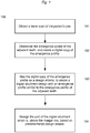
- FIG. 1 shows an example of a method 100 according to an embodiment of the invention.
- a bone scan of the patient's jaw is obtained.
- the scan may comprise a dental implant already fixed in the patient's jawbone.
- Obtaining the scan may involve the physical operation of a machine, and performing the scan on the patient.
- Obtaining may also mean loading a previously acquired scan into a computer.
- step 102 the emergence profile(s) of the tooth or teeth adjacent to the site of the wanted abutment are determined, and a digital data representation of this emergence profile is generated.
- the digital abutment design is created, using the digital data representation of the emergence profile of the adjacent teeth, so that the digital abutment design is designed with a substantially similar emergence profile.
- the emergence profile is the part of the digital abutment design that is above the level of the jawbone or implant, up to the margin line on the digital abutment design.
- the upper portion of the digital abutment design is designed.
- the upper portion should have a length of at least 3mm in order to facilitate retention of the final restoration on the abutment.
- the upper portion of the digital abutment design may also be angled relative to the surface of the jawbone. This is done in order to have a viable path of insertion of the final restoration, taking into account the shape and position of the neighbouring teeth.
- the shape and position of the neighbouring teeth is also determined from the bone scan.
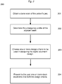
- FIG. 2 shows an example of the method 200 according to another embodiment of the invention.
- a bone scan of the patient's jaw is obtained.
- the scan may comprise a dental implant already fixed in the patient's jawbone.
- Obtaining the scan may involve the physical operation of a machine, and performing the scan on the patient.
- Obtaining may also mean loading a previously acquired scan into a computer.
- the emergence profile(s) of the tooth or teeth adjacent to the site of the wanted abutment are determined, and a digital data representation of the emergence profile is generated.
- the user may define a set of design criteria to be used in selecting a digital abutment design.
- the design software may already have default design criteria, that are used unless changed by the user.
- the design software checks one or more stock abutment libraries that are available in digital form. A check is performed for each available abutment, to see if all predetermined design criteria are fulfilled. If one or more stock abutments fulfil all the predetermined design criteria, these possible abutments are shown to the user, who may then select the abutment of his/her choice. Alternatively, if none of the stock abutments available to the user fulfil all criteria, an error message may be shown, and the user may be prompted to design a customized abutment instead, for example using the method described in Figure 1 . In another alternative, the stock abutment which most closely fulfils the design criteria may be presented to the user, possibly with a warning describing which of the design criteria are not fulfilled.
- Figure 3a shows a bone scan 300 as disclosed herein.
- the bone scan 300 shows the surface of the jawbone 301, a dental implant 302 where no abutment has yet been designed or chosen, and any remaining teeth 303 adjacent to the implant position.
- the emergence profile of the adjacent teeth can be determined from this image.
- Dental implants from different manufacturers may have different attachment profiles, and the digital abutment design should be designed to fit the dental implant 302 in the patient's jaw.
- Figure 3b shows the same view as Figure 3a , now comprising an abutment 304 designed according to predetermined design criteria.
- the abutment 304 is in this example designed to emulate the emergence profile of the adjacent teeth.
- the left side of the abutment 304 is designed to emulate the left side of the emergence profile of the tooth adjacent to the left of the abutment 304, and the right side of the abutment 304 is designed to emulate the emergence profile of the right side of the adjacent tooth to the right side of the abutment 304.
- the prep length 305 should be designed to be at is at least 3mm for proper retention and resistance of the final restoration.
- a surface scan showing the surface contour 306 of the gingiva is added.
- the surface scan may also comprise information about the surface of the teeth.
- the surface scan may be obtained by for example scanning a physical impression taken of the patient's teeth and gums or a gypsum model of the patient's teeth or gums using a desktop scanner, for example the D900 by 3Shape.
- the surface scan may also be obtained by using an intraoral scanner, such as the TRIOS by 3Shape.
- the surface scan gives information about the surface level of the gingiva 306.
- FIG. 3a-3c have shown an embodiment of the invention wherein the abutment to be designed is for a molar, the invention may equally be practiced on premolars, canines or incisors.
- the predetermined design criteria may also comprise a lingual margin depth of no more than 0.5 mm, a mesial and distal margin depth of no more than 1mm, and a facial margin depth of no more than 1.5mm. If the margin line is placed deeper than this with respect to the surface of the gingiva, it will become difficult to remove any excess cement from the patient's mouth once the restoration has been placed on the final abutment.
- the shape of the abutment can be used to define an appropriate path of insertion of the final restoration. Normally, this design parameter would be determined based on a surface scan. However, using the disclosure of this invention, it is possible to design the customized abutment to define an appropriate path of insertion of the final restoration using only the bone scan, since the surface of both the jawbone and the adjacent teeth is visible in the bone scan.
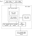
- Fig. 4 shows a schematic of a system according to an embodiment of the invention.
- the system 400 comprises a computer device 402 comprising a computer readable medium 404 and a microprocessor 403.
- the system further comprises a visual display unit 407, a computer keyboard 405 and a computer mouse 406 for entering data and activating virtual buttons visualized on the visual display unit 407.
- the visual display unit 407 may for example be a computer screen.
- the computer device 402 is capable of obtaining digital representations of at least a part of a patient's jaw including the surface of the jawbone from e.g. a CBCT scanner 401a.
- the obtained digital representations can be stored in the computer readable medium 404 and provided to the processor 403.
- the computer device 402 is further capable of receiving a digital 3D representation of the surfaces of the patient's set of teeth and gingiva from a image acquisition device 401b, for example a 3D scanning device, such as the TRIOS intra-oral scanner manufactured by 3shape TRIOS A/S, or capable of receiving scan data from such a 3D scanning device and forming a digital 3D representation of the patient's set of teeth and/or gingiva based on such scan data.
- the received or formed digital 3D representation can be stored in the computer readable medium 404 and provided to the microprocessor 403.
- the system 400 is configured for allowing an operator to design a customized dental abutment using information obtained from the bone scan and/or the surface scan, with limits being set based on pre-determined design criteria. This can be realized for example by displaying the digital representation of the patient's jaw on the visual display unit 407, and the operator can then visualize his/her abutment design on the visual display unit, with respect to the surface of the patient's jaw.
- the system comprises a unit 408 for transmitting the digital designs of the customized dental abutment to e.g. a computer aided manufacturing (CAM) device 409 for manufacturing the customized dental abutments or to another computer system e.g. located at a milling center where the customized dental abutments are manufactured.
- the unit for transmitting can be a wired or a wireless connection, and the transmission may be done for example using the internet or File Transfer Protocol (FTP).
- FTP File Transfer Protocol
- the 3D scanning of the patient's set of teeth and/or gingiva using the 3D scanning device 401 b, and/or the bone scan using the CBCT scanner 401b can be performed at a dentist while the designing of the customized dental abutment is performed at a dental laboratory.
- the digital 3D representation of the patient's set of teeth and/or the 3D representation of the patient's jaw acquired from the CBCT scanner can be provided via an internet connection between the dentist and the dental laboratory.
- the system 400 as shown is an illustrative example.
- the computer device 402 may comprise more than one micro processor 403 and/or more than one computer readable medium 404, the visual display unit 407 may be integrated in the computer device 402 or be separate from the computer device 402, etc.
- a claim may refer to any of the preceding claims, and "any” is understood to mean “any one or more” of the preceding claims.
- the features of the method described above and in the following may be implemented in software and carried out on a data processing system or other processing means caused by the execution of computer-executable instructions.
- the instructions may be program code means loaded in a memory, such as a RAM, from a storage medium or from another computer via a computer network.
- the described features may be implemented by hardwired circuitry instead of software or in combination with software.
Landscapes
- Health & Medical Sciences (AREA)
- Life Sciences & Earth Sciences (AREA)
- Engineering & Computer Science (AREA)
- Animal Behavior & Ethology (AREA)
- General Health & Medical Sciences (AREA)
- Public Health (AREA)
- Veterinary Medicine (AREA)
- Medical Informatics (AREA)
- Oral & Maxillofacial Surgery (AREA)
- Dentistry (AREA)
- Epidemiology (AREA)
- Physics & Mathematics (AREA)
- Biophysics (AREA)
- Biomedical Technology (AREA)
- Surgery (AREA)
- High Energy & Nuclear Physics (AREA)
- Orthopedic Medicine & Surgery (AREA)
- Nuclear Medicine, Radiotherapy & Molecular Imaging (AREA)
- Optics & Photonics (AREA)
- Pathology (AREA)
- Radiology & Medical Imaging (AREA)
- Molecular Biology (AREA)
- Heart & Thoracic Surgery (AREA)
- Theoretical Computer Science (AREA)
- Pulmonology (AREA)
- Computer Hardware Design (AREA)
- Evolutionary Computation (AREA)
- Geometry (AREA)
- General Engineering & Computer Science (AREA)
- General Physics & Mathematics (AREA)
- Dental Tools And Instruments Or Auxiliary Dental Instruments (AREA)
Claims (10)
- Verfahren zum Erzeugen eines digitalen Abutmentdesigns eines kundenspezifischen Zahnabutments, wobei das Verfahren umfasst:- Erhalten eines Knochenscans (300), der eine digitale Darstellung von mindestens einem Teil des Kiefers eines Patienten einschließlich der Oberfläche des Kieferknochens (301) umfasst; und- Erzeugen des digitalen Abutmentdesigns (304) des kundenspezifischen Zahnabutments; wobei das digitale Abutmentdesign (304) zumindest teilweise auf dem Erfüllen einer Reihe von vordefinierten Designkriterien basiert, die die Beziehung zwischen der digitalen Darstellung des Kieferknochens und dem digitalen Abutmentdesign umfassen;dadurch gekennzeichnet, dass das Verfahren weiter umfasst:- Segmentieren der Voxeldaten des Knochenscans, um zumindest eine digitale Knochenoberflächendarstellung (301) bereitzustellen; und- Verwenden der digitalen Knochenoberflächendarstellung (301), um das digitale Design des kundenspezifischen Zahnabutments (304) einzuschränken, um zu bestätigen, dass die vordefinierten Designkriterien erfüllt wurden.
- Verfahren nach einem der vorstehenden Ansprüche, wobei der Knochenscan einen CBCT-Scan umfasst.
- Verfahren nach einem der vorstehenden Ansprüche, wobei die Beziehung zwischen der digitalen Darstellung des Kieferknochens (301) und dem digitalen Abutmentdesign (304) die Beziehung zwischen der Oberfläche der digitalen Darstellung des Kieferknochens (301) und der Außenfläche des digitalen Abutmentdesigns (304) umfasst.
- Verfahren nach einem der vorstehenden Ansprüche, wobei der Knochenscan weiter Informationen über die Form und Position von zumindest einem Teil eines oder mehrerer Zähne (303) benachbart zu der gewünschten Abutmentposition umfasst.
- Verfahren nach einem der vorstehenden Ansprüche, wobei die vorbestimmten Designkriterien das Anpassen eines Entstehungsprofils des Abutments an ein Entstehungsprofil des subgingivalen Teils des zumindest einen benachbarten vorhandenen Zahnes (303) umfassen.
- Verfahren nach Anspruch 6, wobei das Entstehungsprofil des benachbarten Zahnes (303) bestimmt und digital kopiert wird, und die digitale Kopie verwendet wird, um das Entstehungsprofil des Abutments (304) zu designen.
- Verfahren nach einem der vorstehenden Ansprüche, wobei das Verfahren weiter umfasst:- Erhalten eines Oberflächenscans von zumindest einem Teil des Kiefers eines Patienten, der zumindest einen Teil der Oberfläche der umgebenden Gingiva (306) umfasst; und- Platzieren einer Randlinie des Abutments an einer vorbestimmten Position in Bezug auf die Oberfläche der Gingiva (306) und der Oberfläche des Kiefer-knochens (301).
- Verfahren nach einem der vorstehenden Ansprüche, wobei die vordefinierten Designkriterien Schwellenwerte umfassen, die bei einer Verletzung eine Warnung erzeugen.
- Verfahren nach einem der vorstehenden Ansprüche, wobei der Einbringungsweg einer finalen Restauration nur unter Verwendung des Knochenscans bestimmt wird.
- Computerprogrammprodukt, das Programmcodemittel umfasst, die konfiguriert sind, um einen Computer zu veranlassen, die Schritte des Verfahrens nach einem der Ansprüche 1-9 durchzuführen.
Applications Claiming Priority (2)
| Application Number | Priority Date | Filing Date | Title |
|---|---|---|---|
| DKPA201470816 | 2014-12-22 | ||
| PCT/EP2015/080773 WO2016102451A1 (en) | 2014-12-22 | 2015-12-21 | Using a cbct bone scan to design a dental abutment |
Publications (2)
| Publication Number | Publication Date |
|---|---|
| EP3236879A1 EP3236879A1 (de) | 2017-11-01 |
| EP3236879B1 true EP3236879B1 (de) | 2020-02-05 |
Family
ID=54937088
Family Applications (1)
| Application Number | Title | Priority Date | Filing Date |
|---|---|---|---|
| EP15813452.8A Active EP3236879B1 (de) | 2014-12-22 | 2015-12-21 | Verwendung eines cbct-knochenscans zum entwurf einer zahnstütze |
Country Status (3)
| Country | Link |
|---|---|
| US (1) | US10602992B2 (de) |
| EP (1) | EP3236879B1 (de) |
| WO (1) | WO2016102451A1 (de) |
Families Citing this family (6)
| Publication number | Priority date | Publication date | Assignee | Title |
|---|---|---|---|---|
| KR102425718B1 (ko) * | 2020-01-03 | 2022-07-27 | 주식회사 메디트 | 통합 라이브러리 사용 방법 |
| US11562547B2 (en) | 2020-02-28 | 2023-01-24 | James R. Glidewell Dental Ceramics, Inc. | Digital block out of digital preparation |
| CN111489445B (zh) * | 2020-03-12 | 2023-05-23 | 浙江工业大学 | 一种种植牙基台穿龈面生成方法 |
| CN112957147A (zh) * | 2021-03-23 | 2021-06-15 | 郝晋玲 | 利用生物解剖结构愈合扫描体制作牙冠或基台的方法 |
| KR102577343B1 (ko) * | 2021-07-30 | 2023-09-12 | 오스템임플란트 주식회사 | 서지컬 가이드를 디자인하기 위한 가상 어버트먼트의 추천 방법 및 장치 |
| WO2023085474A1 (ko) * | 2021-11-15 | 2023-05-19 | 주식회사 쿠보텍 | 3d 개인 맞춤형 치과용 골 표면 임플란트 제조방법 |
Citations (6)
| Publication number | Priority date | Publication date | Assignee | Title |
|---|---|---|---|---|
| US20090042167A1 (en) * | 2004-09-14 | 2009-02-12 | Oratio B.V. | Method of Manufacturing and Installing a Ceramic Dental Implant with an Aesthetic Implant Abutment |
| US20100105009A1 (en) * | 2008-10-29 | 2010-04-29 | Inpronto Inc. | System, Method And Apparatus For Tooth Implants |
| US20110086328A1 (en) * | 2009-10-09 | 2011-04-14 | Todd Wedeking | Method and apparatus for producing a dental implant |
| US20120072178A1 (en) * | 2010-09-17 | 2012-03-22 | Nobel Biocare Ab | Adjusting dental prostheses based on soft tissue |
| WO2013092744A1 (en) * | 2011-12-21 | 2013-06-27 | 3Shape A/S | Virtually designing a customized healing abutment |
| WO2014064165A1 (en) * | 2012-10-23 | 2014-05-01 | 3Shape A/S | Designing a dental restoration |
Family Cites Families (11)
| Publication number | Priority date | Publication date | Assignee | Title |
|---|---|---|---|---|
| US7708557B2 (en) | 2006-10-16 | 2010-05-04 | Natural Dental Implants Ag | Customized dental prosthesis for periodontal- or osseointegration, and related systems and methods |
| ES2739460T3 (es) | 2008-03-19 | 2020-01-31 | Nobel Biocare Services Ag | Reposicionamiento de componentes relacionados con procedimientos quirúrgicos craneales en un paciente |
| US20100105011A1 (en) * | 2008-10-29 | 2010-04-29 | Inpronto Inc. | System, Method And Apparatus For Tooth Implant Planning And Tooth Implant Kits |
| US8246870B2 (en) * | 2009-06-01 | 2012-08-21 | Layton Grant H | Dental implant system and method of use |
| WO2012003517A2 (en) * | 2010-07-02 | 2012-01-05 | Llop Daniel R | An apparatus and digital methodology for preparation of a dental implant surgical site for the promotion of a desired emergent sulcus |
| US20120070802A1 (en) | 2010-09-17 | 2012-03-22 | Woodward Iii Herbert S | Dental implant fabrication and insertion methods and personalized dental implant for use therein |
| EP2444028B1 (de) * | 2010-10-20 | 2014-01-08 | Dentsply IH AB | Verfahren zur Bereitstellung einer patientenspezifischen Zahnimplantatfixieranordnung |
| DK3679888T3 (da) * | 2011-02-23 | 2022-01-24 | 3Shape As | Fremgangsmåde til modificering af gingiva-delen af en virtuel model af et tandsæt |
| JP5834136B2 (ja) | 2011-05-16 | 2015-12-16 | バイオメット・3アイ・エルエルシー | 仮の補綴物アセンブリ |
| US9839496B2 (en) * | 2013-02-19 | 2017-12-12 | Biomet 3I, Llc | Patient-specific dental prosthesis and gingival contouring developed by predictive modeling |
| US9763757B2 (en) * | 2014-05-19 | 2017-09-19 | National Dentex, Llc | Method for creating a virtual oral-maxillofacial anatomical representation |
-
2015
- 2015-12-21 WO PCT/EP2015/080773 patent/WO2016102451A1/en not_active Ceased
- 2015-12-21 US US15/538,819 patent/US10602992B2/en active Active
- 2015-12-21 EP EP15813452.8A patent/EP3236879B1/de active Active
Patent Citations (6)
| Publication number | Priority date | Publication date | Assignee | Title |
|---|---|---|---|---|
| US20090042167A1 (en) * | 2004-09-14 | 2009-02-12 | Oratio B.V. | Method of Manufacturing and Installing a Ceramic Dental Implant with an Aesthetic Implant Abutment |
| US20100105009A1 (en) * | 2008-10-29 | 2010-04-29 | Inpronto Inc. | System, Method And Apparatus For Tooth Implants |
| US20110086328A1 (en) * | 2009-10-09 | 2011-04-14 | Todd Wedeking | Method and apparatus for producing a dental implant |
| US20120072178A1 (en) * | 2010-09-17 | 2012-03-22 | Nobel Biocare Ab | Adjusting dental prostheses based on soft tissue |
| WO2013092744A1 (en) * | 2011-12-21 | 2013-06-27 | 3Shape A/S | Virtually designing a customized healing abutment |
| WO2014064165A1 (en) * | 2012-10-23 | 2014-05-01 | 3Shape A/S | Designing a dental restoration |
Also Published As
| Publication number | Publication date |
|---|---|
| WO2016102451A1 (en) | 2016-06-30 |
| US20180000569A1 (en) | 2018-01-04 |
| US10602992B2 (en) | 2020-03-31 |
| EP3236879A1 (de) | 2017-11-01 |
Similar Documents
| Publication | Publication Date | Title |
|---|---|---|
| US20230293261A1 (en) | Dental preparation guide | |
| US10743968B2 (en) | Creating a digital restoration design | |
| JP5427778B2 (ja) | 歯科的プランニングのための方法およびシステム | |
| US10327873B2 (en) | Method, system and user interface for creating a digital design for use in manufacturing a molding-shell for a dental restoration | |
| EP3243482B1 (de) | Verfahren zur anleitung eines zahnimplantatplans, vorrichtung dafür und aufzeichnungsmedium dafür | |
| JP6334409B2 (ja) | カスタマイズド治療用支台歯の仮想設計 | |
| CN101257858B (zh) | (半)自动种植牙设计的方法 | |
| US9767223B2 (en) | Designing a virtual preparation and a virtual gingival | |
| US10602992B2 (en) | Using a CBCT bone scan to design a dental abutment | |
| JP6248109B2 (ja) | 改善された仮想スプリント | |
| US20200022790A1 (en) | Common Placement Support for Artificial Teeth | |
| EP2877118B1 (de) | Entwurf eines dentalen positioniergestells | |
| CN115666441B (zh) | 用于评估牙齿准备表面的方法和系统 | |
| EP3108850A2 (de) | Erzeugung eines designs für ein zahnrestauratives produkt aus zahnbildern | |
| JP2015531640A (ja) | デジタルスプリント | |
| CN118634032B (zh) | 用于生成用于患者的目标拔除对象的虚拟拔除过程的模型的方法和系统 | |
| KR102363904B1 (ko) | 치과용 어버트먼트를 제공하는 방법 | |
| BR102024004817A2 (pt) | Método e sistema para geração de um modelo para uso em um procedimento de extração virtual de um objeto de extração alvejado em um paciente |
Legal Events
| Date | Code | Title | Description |
|---|---|---|---|
| STAA | Information on the status of an ep patent application or granted ep patent |
Free format text: STATUS: THE INTERNATIONAL PUBLICATION HAS BEEN MADE |
|
| PUAI | Public reference made under article 153(3) epc to a published international application that has entered the european phase |
Free format text: ORIGINAL CODE: 0009012 |
|
| STAA | Information on the status of an ep patent application or granted ep patent |
Free format text: STATUS: REQUEST FOR EXAMINATION WAS MADE |
|
| 17P | Request for examination filed |
Effective date: 20170621 |
|
| AK | Designated contracting states |
Kind code of ref document: A1 Designated state(s): AL AT BE BG CH CY CZ DE DK EE ES FI FR GB GR HR HU IE IS IT LI LT LU LV MC MK MT NL NO PL PT RO RS SE SI SK SM TR |
|
| AX | Request for extension of the european patent |
Extension state: BA ME |
|
| DAV | Request for validation of the european patent (deleted) | ||
| DAX | Request for extension of the european patent (deleted) | ||
| PUAG | Search results despatched under rule 164(2) epc together with communication from examining division |
Free format text: ORIGINAL CODE: 0009017 |
|
| STAA | Information on the status of an ep patent application or granted ep patent |
Free format text: STATUS: EXAMINATION IS IN PROGRESS |
|
| 17Q | First examination report despatched |
Effective date: 20180719 |
|
| B565 | Issuance of search results under rule 164(2) epc |
Effective date: 20180719 |
|
| RIC1 | Information provided on ipc code assigned before grant |
Ipc: A61C 8/00 20060101ALI20180716BHEP Ipc: A61C 13/00 20060101AFI20180716BHEP |
|
| GRAP | Despatch of communication of intention to grant a patent |
Free format text: ORIGINAL CODE: EPIDOSNIGR1 |
|
| STAA | Information on the status of an ep patent application or granted ep patent |
Free format text: STATUS: GRANT OF PATENT IS INTENDED |
|
| INTG | Intention to grant announced |
Effective date: 20190710 |
|
| GRAS | Grant fee paid |
Free format text: ORIGINAL CODE: EPIDOSNIGR3 |
|
| GRAA | (expected) grant |
Free format text: ORIGINAL CODE: 0009210 |
|
| STAA | Information on the status of an ep patent application or granted ep patent |
Free format text: STATUS: THE PATENT HAS BEEN GRANTED |
|
| AK | Designated contracting states |
Kind code of ref document: B1 Designated state(s): AL AT BE BG CH CY CZ DE DK EE ES FI FR GB GR HR HU IE IS IT LI LT LU LV MC MK MT NL NO PL PT RO RS SE SI SK SM TR |
|
| REG | Reference to a national code |
Ref country code: GB Ref legal event code: FG4D |
|
| REG | Reference to a national code |
Ref country code: AT Ref legal event code: REF Ref document number: 1229400 Country of ref document: AT Kind code of ref document: T Effective date: 20200215 |
|
| REG | Reference to a national code |
Ref country code: DE Ref legal event code: R096 Ref document number: 602015046459 Country of ref document: DE |
|
| REG | Reference to a national code |
Ref country code: IE Ref legal event code: FG4D |
|
| REG | Reference to a national code |
Ref country code: CH Ref legal event code: EP |
|
| REG | Reference to a national code |
Ref country code: NL Ref legal event code: MP Effective date: 20200205 |
|
| PG25 | Lapsed in a contracting state [announced via postgrant information from national office to epo] |
Ref country code: PT Free format text: LAPSE BECAUSE OF FAILURE TO SUBMIT A TRANSLATION OF THE DESCRIPTION OR TO PAY THE FEE WITHIN THE PRESCRIBED TIME-LIMIT Effective date: 20200628 Ref country code: NO Free format text: LAPSE BECAUSE OF FAILURE TO SUBMIT A TRANSLATION OF THE DESCRIPTION OR TO PAY THE FEE WITHIN THE PRESCRIBED TIME-LIMIT Effective date: 20200505 Ref country code: RS Free format text: LAPSE BECAUSE OF FAILURE TO SUBMIT A TRANSLATION OF THE DESCRIPTION OR TO PAY THE FEE WITHIN THE PRESCRIBED TIME-LIMIT Effective date: 20200205 Ref country code: FI Free format text: LAPSE BECAUSE OF FAILURE TO SUBMIT A TRANSLATION OF THE DESCRIPTION OR TO PAY THE FEE WITHIN THE PRESCRIBED TIME-LIMIT Effective date: 20200205 |
|
| REG | Reference to a national code |
Ref country code: LT Ref legal event code: MG4D |
|
| PG25 | Lapsed in a contracting state [announced via postgrant information from national office to epo] |
Ref country code: GR Free format text: LAPSE BECAUSE OF FAILURE TO SUBMIT A TRANSLATION OF THE DESCRIPTION OR TO PAY THE FEE WITHIN THE PRESCRIBED TIME-LIMIT Effective date: 20200506 Ref country code: SE Free format text: LAPSE BECAUSE OF FAILURE TO SUBMIT A TRANSLATION OF THE DESCRIPTION OR TO PAY THE FEE WITHIN THE PRESCRIBED TIME-LIMIT Effective date: 20200205 Ref country code: LV Free format text: LAPSE BECAUSE OF FAILURE TO SUBMIT A TRANSLATION OF THE DESCRIPTION OR TO PAY THE FEE WITHIN THE PRESCRIBED TIME-LIMIT Effective date: 20200205 Ref country code: HR Free format text: LAPSE BECAUSE OF FAILURE TO SUBMIT A TRANSLATION OF THE DESCRIPTION OR TO PAY THE FEE WITHIN THE PRESCRIBED TIME-LIMIT Effective date: 20200205 Ref country code: BG Free format text: LAPSE BECAUSE OF FAILURE TO SUBMIT A TRANSLATION OF THE DESCRIPTION OR TO PAY THE FEE WITHIN THE PRESCRIBED TIME-LIMIT Effective date: 20200505 Ref country code: IS Free format text: LAPSE BECAUSE OF FAILURE TO SUBMIT A TRANSLATION OF THE DESCRIPTION OR TO PAY THE FEE WITHIN THE PRESCRIBED TIME-LIMIT Effective date: 20200605 |
|
| PG25 | Lapsed in a contracting state [announced via postgrant information from national office to epo] |
Ref country code: NL Free format text: LAPSE BECAUSE OF FAILURE TO SUBMIT A TRANSLATION OF THE DESCRIPTION OR TO PAY THE FEE WITHIN THE PRESCRIBED TIME-LIMIT Effective date: 20200205 |
|
| PG25 | Lapsed in a contracting state [announced via postgrant information from national office to epo] |
Ref country code: EE Free format text: LAPSE BECAUSE OF FAILURE TO SUBMIT A TRANSLATION OF THE DESCRIPTION OR TO PAY THE FEE WITHIN THE PRESCRIBED TIME-LIMIT Effective date: 20200205 Ref country code: SM Free format text: LAPSE BECAUSE OF FAILURE TO SUBMIT A TRANSLATION OF THE DESCRIPTION OR TO PAY THE FEE WITHIN THE PRESCRIBED TIME-LIMIT Effective date: 20200205 Ref country code: CZ Free format text: LAPSE BECAUSE OF FAILURE TO SUBMIT A TRANSLATION OF THE DESCRIPTION OR TO PAY THE FEE WITHIN THE PRESCRIBED TIME-LIMIT Effective date: 20200205 Ref country code: RO Free format text: LAPSE BECAUSE OF FAILURE TO SUBMIT A TRANSLATION OF THE DESCRIPTION OR TO PAY THE FEE WITHIN THE PRESCRIBED TIME-LIMIT Effective date: 20200205 Ref country code: SK Free format text: LAPSE BECAUSE OF FAILURE TO SUBMIT A TRANSLATION OF THE DESCRIPTION OR TO PAY THE FEE WITHIN THE PRESCRIBED TIME-LIMIT Effective date: 20200205 Ref country code: DK Free format text: LAPSE BECAUSE OF FAILURE TO SUBMIT A TRANSLATION OF THE DESCRIPTION OR TO PAY THE FEE WITHIN THE PRESCRIBED TIME-LIMIT Effective date: 20200205 Ref country code: ES Free format text: LAPSE BECAUSE OF FAILURE TO SUBMIT A TRANSLATION OF THE DESCRIPTION OR TO PAY THE FEE WITHIN THE PRESCRIBED TIME-LIMIT Effective date: 20200205 Ref country code: LT Free format text: LAPSE BECAUSE OF FAILURE TO SUBMIT A TRANSLATION OF THE DESCRIPTION OR TO PAY THE FEE WITHIN THE PRESCRIBED TIME-LIMIT Effective date: 20200205 |
|
| REG | Reference to a national code |
Ref country code: DE Ref legal event code: R097 Ref document number: 602015046459 Country of ref document: DE |
|
| REG | Reference to a national code |
Ref country code: AT Ref legal event code: MK05 Ref document number: 1229400 Country of ref document: AT Kind code of ref document: T Effective date: 20200205 |
|
| PLBE | No opposition filed within time limit |
Free format text: ORIGINAL CODE: 0009261 |
|
| STAA | Information on the status of an ep patent application or granted ep patent |
Free format text: STATUS: NO OPPOSITION FILED WITHIN TIME LIMIT |
|
| 26N | No opposition filed |
Effective date: 20201106 |
|
| PG25 | Lapsed in a contracting state [announced via postgrant information from national office to epo] |
Ref country code: AT Free format text: LAPSE BECAUSE OF FAILURE TO SUBMIT A TRANSLATION OF THE DESCRIPTION OR TO PAY THE FEE WITHIN THE PRESCRIBED TIME-LIMIT Effective date: 20200205 Ref country code: IT Free format text: LAPSE BECAUSE OF FAILURE TO SUBMIT A TRANSLATION OF THE DESCRIPTION OR TO PAY THE FEE WITHIN THE PRESCRIBED TIME-LIMIT Effective date: 20200205 |
|
| PG25 | Lapsed in a contracting state [announced via postgrant information from national office to epo] |
Ref country code: SI Free format text: LAPSE BECAUSE OF FAILURE TO SUBMIT A TRANSLATION OF THE DESCRIPTION OR TO PAY THE FEE WITHIN THE PRESCRIBED TIME-LIMIT Effective date: 20200205 Ref country code: PL Free format text: LAPSE BECAUSE OF FAILURE TO SUBMIT A TRANSLATION OF THE DESCRIPTION OR TO PAY THE FEE WITHIN THE PRESCRIBED TIME-LIMIT Effective date: 20200205 |
|
| REG | Reference to a national code |
Ref country code: CH Ref legal event code: PL |
|
| PG25 | Lapsed in a contracting state [announced via postgrant information from national office to epo] |
Ref country code: MC Free format text: LAPSE BECAUSE OF FAILURE TO SUBMIT A TRANSLATION OF THE DESCRIPTION OR TO PAY THE FEE WITHIN THE PRESCRIBED TIME-LIMIT Effective date: 20200205 |
|
| REG | Reference to a national code |
Ref country code: BE Ref legal event code: MM Effective date: 20201231 |
|
| PG25 | Lapsed in a contracting state [announced via postgrant information from national office to epo] |
Ref country code: IE Free format text: LAPSE BECAUSE OF NON-PAYMENT OF DUE FEES Effective date: 20201221 Ref country code: LU Free format text: LAPSE BECAUSE OF NON-PAYMENT OF DUE FEES Effective date: 20201221 |
|
| PG25 | Lapsed in a contracting state [announced via postgrant information from national office to epo] |
Ref country code: CH Free format text: LAPSE BECAUSE OF NON-PAYMENT OF DUE FEES Effective date: 20201231 Ref country code: LI Free format text: LAPSE BECAUSE OF NON-PAYMENT OF DUE FEES Effective date: 20201231 |
|
| PG25 | Lapsed in a contracting state [announced via postgrant information from national office to epo] |
Ref country code: TR Free format text: LAPSE BECAUSE OF FAILURE TO SUBMIT A TRANSLATION OF THE DESCRIPTION OR TO PAY THE FEE WITHIN THE PRESCRIBED TIME-LIMIT Effective date: 20200205 Ref country code: MT Free format text: LAPSE BECAUSE OF FAILURE TO SUBMIT A TRANSLATION OF THE DESCRIPTION OR TO PAY THE FEE WITHIN THE PRESCRIBED TIME-LIMIT Effective date: 20200205 Ref country code: CY Free format text: LAPSE BECAUSE OF FAILURE TO SUBMIT A TRANSLATION OF THE DESCRIPTION OR TO PAY THE FEE WITHIN THE PRESCRIBED TIME-LIMIT Effective date: 20200205 |
|
| PG25 | Lapsed in a contracting state [announced via postgrant information from national office to epo] |
Ref country code: MK Free format text: LAPSE BECAUSE OF FAILURE TO SUBMIT A TRANSLATION OF THE DESCRIPTION OR TO PAY THE FEE WITHIN THE PRESCRIBED TIME-LIMIT Effective date: 20200205 Ref country code: AL Free format text: LAPSE BECAUSE OF FAILURE TO SUBMIT A TRANSLATION OF THE DESCRIPTION OR TO PAY THE FEE WITHIN THE PRESCRIBED TIME-LIMIT Effective date: 20200205 |
|
| PG25 | Lapsed in a contracting state [announced via postgrant information from national office to epo] |
Ref country code: BE Free format text: LAPSE BECAUSE OF NON-PAYMENT OF DUE FEES Effective date: 20201231 |
|
| P01 | Opt-out of the competence of the unified patent court (upc) registered |
Effective date: 20230529 |
|
| PGFP | Annual fee paid to national office [announced via postgrant information from national office to epo] |
Ref country code: DE Payment date: 20251211 Year of fee payment: 11 |
|
| PGFP | Annual fee paid to national office [announced via postgrant information from national office to epo] |
Ref country code: GB Payment date: 20251219 Year of fee payment: 11 |
|
| PGFP | Annual fee paid to national office [announced via postgrant information from national office to epo] |
Ref country code: FR Payment date: 20251229 Year of fee payment: 11 |