EP3237117B1 - Passage tournant d'un bloc de vanne d'encollage - Google Patents
Passage tournant d'un bloc de vanne d'encollage Download PDFInfo
- Publication number
- EP3237117B1 EP3237117B1 EP15805394.2A EP15805394A EP3237117B1 EP 3237117 B1 EP3237117 B1 EP 3237117B1 EP 15805394 A EP15805394 A EP 15805394A EP 3237117 B1 EP3237117 B1 EP 3237117B1
- Authority
- EP
- European Patent Office
- Prior art keywords
- glue
- receiving part
- valve arrangement
- filter
- filter receiving
- Prior art date
- Legal status (The legal status is an assumption and is not a legal conclusion. Google has not performed a legal analysis and makes no representation as to the accuracy of the status listed.)
- Active
Links
Images
Classifications
-
- B—PERFORMING OPERATIONS; TRANSPORTING
- B05—SPRAYING OR ATOMISING IN GENERAL; APPLYING FLUENT MATERIALS TO SURFACES, IN GENERAL
- B05C—APPARATUS FOR APPLYING FLUENT MATERIALS TO SURFACES, IN GENERAL
- B05C11/00—Component parts, details or accessories not specifically provided for in groups B05C1/00 - B05C9/00
- B05C11/10—Storage, supply or control of liquid or other fluent material; Recovery of excess liquid or other fluent material
-
- B—PERFORMING OPERATIONS; TRANSPORTING
- B05—SPRAYING OR ATOMISING IN GENERAL; APPLYING FLUENT MATERIALS TO SURFACES, IN GENERAL
- B05B—SPRAYING APPARATUS; ATOMISING APPARATUS; NOZZLES
- B05B15/00—Details of spraying plant or spraying apparatus not otherwise provided for; Accessories
- B05B15/40—Filters located upstream of the spraying outlets
-
- B—PERFORMING OPERATIONS; TRANSPORTING
- B05—SPRAYING OR ATOMISING IN GENERAL; APPLYING FLUENT MATERIALS TO SURFACES, IN GENERAL
- B05C—APPARATUS FOR APPLYING FLUENT MATERIALS TO SURFACES, IN GENERAL
- B05C11/00—Component parts, details or accessories not specifically provided for in groups B05C1/00 - B05C9/00
- B05C11/10—Storage, supply or control of liquid or other fluent material; Recovery of excess liquid or other fluent material
- B05C11/1002—Means for controlling supply, i.e. flow or pressure, of liquid or other fluent material to the applying apparatus, e.g. valves
- B05C11/1026—Valves
-
- B—PERFORMING OPERATIONS; TRANSPORTING
- B05—SPRAYING OR ATOMISING IN GENERAL; APPLYING FLUENT MATERIALS TO SURFACES, IN GENERAL
- B05C—APPARATUS FOR APPLYING FLUENT MATERIALS TO SURFACES, IN GENERAL
- B05C11/00—Component parts, details or accessories not specifically provided for in groups B05C1/00 - B05C9/00
- B05C11/10—Storage, supply or control of liquid or other fluent material; Recovery of excess liquid or other fluent material
- B05C11/1002—Means for controlling supply, i.e. flow or pressure, of liquid or other fluent material to the applying apparatus, e.g. valves
- B05C11/1034—Means for controlling supply, i.e. flow or pressure, of liquid or other fluent material to the applying apparatus, e.g. valves specially designed for conducting intermittent application of small quantities, e.g. drops, of coating material
-
- B—PERFORMING OPERATIONS; TRANSPORTING
- B05—SPRAYING OR ATOMISING IN GENERAL; APPLYING FLUENT MATERIALS TO SURFACES, IN GENERAL
- B05C—APPARATUS FOR APPLYING FLUENT MATERIALS TO SURFACES, IN GENERAL
- B05C5/00—Apparatus in which liquid or other fluent material is projected, poured or allowed to flow on to the surface of the work
- B05C5/02—Apparatus in which liquid or other fluent material is projected, poured or allowed to flow on to the surface of the work the liquid or other fluent material being discharged through an outlet orifice by pressure, e.g. from an outlet device in contact or almost in contact, with the work
- B05C5/027—Coating heads with several outlets, e.g. aligned transversally to the moving direction of a web to be coated
- B05C5/0275—Coating heads with several outlets, e.g. aligned transversally to the moving direction of a web to be coated flow controlled, e.g. by a valve
- B05C5/0279—Coating heads with several outlets, e.g. aligned transversally to the moving direction of a web to be coated flow controlled, e.g. by a valve independently, e.g. individually, flow controlled
-
- F—MECHANICAL ENGINEERING; LIGHTING; HEATING; WEAPONS; BLASTING
- F16—ENGINEERING ELEMENTS AND UNITS; GENERAL MEASURES FOR PRODUCING AND MAINTAINING EFFECTIVE FUNCTIONING OF MACHINES OR INSTALLATIONS; THERMAL INSULATION IN GENERAL
- F16L—PIPES; JOINTS OR FITTINGS FOR PIPES; SUPPORTS FOR PIPES, CABLES OR PROTECTIVE TUBING; MEANS FOR THERMAL INSULATION IN GENERAL
- F16L27/00—Adjustable joints; Joints allowing movement
- F16L27/08—Adjustable joints; Joints allowing movement allowing adjustment or movement only about the axis of one pipe
- F16L27/0804—Adjustable joints; Joints allowing movement allowing adjustment or movement only about the axis of one pipe the fluid passing axially from one joint element to another
- F16L27/0808—Adjustable joints; Joints allowing movement allowing adjustment or movement only about the axis of one pipe the fluid passing axially from one joint element to another the joint elements extending coaxially for some distance from their point of separation
- F16L27/0824—Adjustable joints; Joints allowing movement allowing adjustment or movement only about the axis of one pipe the fluid passing axially from one joint element to another the joint elements extending coaxially for some distance from their point of separation with ball or roller bearings
- F16L27/0828—Adjustable joints; Joints allowing movement allowing adjustment or movement only about the axis of one pipe the fluid passing axially from one joint element to another the joint elements extending coaxially for some distance from their point of separation with ball or roller bearings having radial bearings
Definitions
- the entire filter holder can simply be replaced with a new filter holder with a new filter.
- the filter of the rotary feedthrough can be held in the glue channel by means of a press ring that is seated in a central bore in the filter receiving part.
- the central bore preferably forms the glue channel or is part of it.
- the second connection part of the rotary joint part is detachably connected to the hose-like glue line, in particular by a screw connection with a glue line connection part of the hose-like glue line.
- the first and second connection parts can therefore be rotated relative to one another, which enables the relative movement between the hose-like glue line on the one hand and the base body of the valve arrangement on the other.
- the rotatable mounting of the second connection part on the first connection part is then part of the rotary joint of the rotary joint part.
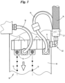
- the dosing or closing element is moved back and forth, in particular in cycles, between an open position in which glue can escape from the glue valve 14 and a closed position in which the glue cannot escape.
- Each of the individual modules 11 has a substantially solid base body 15.
- a base body can also be designed in the manner of a housing, for example.
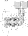
- the glue channel section 22.1 runs within a rotary joint part 23 of the rotary union 20.
- the radial inner side of the first connecting part 24 and the radial outer side of the second connecting part 25, specifically the second end piece 27 of the second connecting part 25, form the outer ring and the inner ring of the ball bearing 29, respectively. More precisely, corresponding annular recesses are incorporated into the corresponding surfaces of the first connecting part 24 and the second connecting part 25, respectively.
- the filter receiving part 32 is connected to the base body 15 by means of a screw connection on the side facing the base body 15. In the present case, an end piece 41 of the filter receiving part 32 is screwed into a suitable threaded hole in the base body 15.
- the shown design of the rotary feedthrough 20 with detachably connected components offers, among other things, the particular advantage of being able to easily replace the filter 34 if necessary.
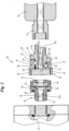
- Both alternatives of the swivel joint part 23 of the Fig.3 optically separated from each other by a dash-dotted double line, differ from the swivel part 23 of the Fig.2 firstly, because the swivel joint part 23 of the Fig.3 the second connecting part 25 is not designed as an angle piece, but as a straight component, in particular symmetrical to a longitudinal central axis.
- first and second end pieces 26, 27 of the second connection part 25 are arranged one behind the other along a common straight axis. For this reason, the axis of rotation about which the hose-like glue line 16 can be rotated by the rotatable mounting of the second connection part 25 on the first connection part 24 coincides with the axis of rotation about which the end piece 27 of the second connection part 25 can be rotated.
- the first connecting part 24 and consequently also the second connecting part 25 can be made shorter while maintaining the required absorption of the bending moments, since the pivot bearing using only a single four-point ball bearing takes up less space than the pivot bearing using a combination of a normal single-row ball bearing and a plain bearing.
Landscapes
- Engineering & Computer Science (AREA)
- General Engineering & Computer Science (AREA)
- Mechanical Engineering (AREA)
- Multiple-Way Valves (AREA)
- Coating Apparatus (AREA)
Claims (12)
- Ensemble formant soupape à colle, ledit ensemble comprenant un élément de dosage commandable, en particulier à fonctionnement électromagnétique, destiné à distribuer de la colle, un corps de base (15) pourvu d'un conduit de colle menant à l'élément de dosage, une conduite de colle (16) de type tuyau qui permet d'amener la colle, provenant d'une source de colle séparée, au conduit de colle, un passage rotatif (20) fixé de manière amovible au corps de base (15) et destiné à relier de manière articulée la conduite de colle (16) de type tuyau au corps de base (15), et un filtre (34) destiné à filtrer la colle, caractérisé en ce que le filtre (34) est associé à une partie de réception de filtre (32) du passage rotatif (20) qui est reliée de manière amovible au corps de base (15), en particulier vissée dans un alésage de celui-ci, et qui est reliée de manière amovible à une partie à articulation rotative (23) du passage rotatif (20), laquelle comprend une articulation rotative (31), notamment par le biais d'une liaison à vis.
- Ensemble formant soupape à colle selon la revendication 1, caractérisé en ce que la partie de réception de filtre (32), dans laquelle siège le filtre (34), comporte un conduit de colle (22.2), notamment central, destiné à l'écoulement de la colle.
- Ensemble formant soupape à colle selon la revendication 1 ou 2, caractérisé en ce que le filtre (34) est maintenu dans le conduit de colle (22.2) au moyen d'une bague de pression (36) siégeant dans un alésage (33), notamment central, de la partie de réception de filtre (32).
- Ensemble formant soupape à colle selon une ou plusieurs des revendications 1 à 3, caractérisé en ce que la partie de réception de filtre (32) comporte un filetage extérieur qui est vissé dans un filetage intérieur correspondant de la partie à articulation rotative (23).
- Ensemble formant soupape à colle selon une ou plusieurs des revendications 1 à 4, caractérisé en ce que la partie à articulation rotative (23) du passage rotatif (20) comporte une première partie de raccordement (24) qui est reliée de manière amovible à la partie de réception de filtre (32) et une deuxième partie de raccordement (25) qui est montée de manière rotative sur la première partie de raccordement (24).
- Ensemble formant soupape à colle selon une ou plusieurs des revendications 1 à 5, caractérisé en ce que la deuxième partie de raccordement (25) de la partie à articulation rotative (23) du passage rotatif (20) est reliée de manière amovible à la conduite de colle (16) de type tuyau, notamment par une liaison à vis avec une partie de raccordement de conduite de colle (21) de la conduite de colle (16) de type tuyau.
- Ensemble formant soupape à colle selon une ou plusieurs des revendications 1 à 6, caractérisé en ce que l'articulation rotative (31) de la partie à articulation rotative (23) ne comporte qu'un seul roulement à billes (à une rangée) (29), en particulier un roulement à billes à quatre points à une rangée (39) .
- Ensemble formant soupape à colle selon une ou plusieurs des revendications 1 à 7, caractérisé en ce que l'articulation rotative (31) comporte en plus du roulement à billes (à une rangée) (29) un palier lisse (30) .
- Ensemble formant soupape à colle selon une ou plusieurs des revendications 1 à 8, caractérisé en ce que la bague extérieure du roulement à billes (29, 39) est formée par la première partie de raccordement (24) de la partie à articulation rotative (23) qui est reliée à la partie de réception de filtre (32) et la bague intérieure dudit roulement à billes est formée par la deuxième partie de raccordement (25) de la partie à articulation rotative (23).
- Ensemble formant soupape à colle selon une ou plusieurs des revendications 1 à 9, caractérisé en ce que la deuxième partie de raccordement (25) de la partie à articulation rotative (23) est coudée et comporte un conduit de colle (22.1), notamment central, qui s'étend jusqu'à l'embout (27) de la deuxième partie de raccordement (25) qui est dirigé vers l'extrémité libre d'une partie de réception de filtre (32) et qui est monté de manière rotative dans un alésage central (40) de la première partie de raccordement (24).
- Ensemble formant soupape à colle selon une ou plusieurs des revendications 1 à 10, caractérisé en ce que le conduit de colle (22.1) de la deuxième partie de raccordement (25) débouche dans le conduit de colle (22.1) de la partie de réception de filtre (32), l'étanchéité (radiale) étant obtenue en ce que l'embout (27) de la deuxième partie de raccordement (25), lequel comprend l'extrémité de conduit de colle correspondante, vient en appui de manière étanche sur un côté d'un joint élastique (annulaire) (37), et la partie de réception de filtre (32), en particulier la bague de pression (36) de la partie de réception de filtre (32), vient en appui de manière étanche sur l'autre côté du joint élastique (37).
- Ensemble formant soupape à colle selon une ou plusieurs des revendications 1 à 11, caractérisé en ce qu'un joint élastique (annulaire) (37) est fixé à la partie de réception de filtre (32) et assure une étanchéité entre le corps de base (15) et la partie de réception de filtre (32) vis-à-vis de la colle lorsque la partie de réception de filtre (32) est fixée au corps de base (15).
Applications Claiming Priority (2)
| Application Number | Priority Date | Filing Date | Title |
|---|---|---|---|
| DE102014018969.4A DE102014018969A1 (de) | 2014-12-22 | 2014-12-22 | Drehdurchführung für eine Leimventileinheit |
| PCT/EP2015/002458 WO2016102043A1 (fr) | 2014-12-22 | 2015-12-07 | Passage tournant d'un bloc de vanne d'encollage |
Publications (2)
| Publication Number | Publication Date |
|---|---|
| EP3237117A1 EP3237117A1 (fr) | 2017-11-01 |
| EP3237117B1 true EP3237117B1 (fr) | 2024-07-03 |
Family
ID=54834784
Family Applications (1)
| Application Number | Title | Priority Date | Filing Date |
|---|---|---|---|
| EP15805394.2A Active EP3237117B1 (fr) | 2014-12-22 | 2015-12-07 | Passage tournant d'un bloc de vanne d'encollage |
Country Status (5)
| Country | Link |
|---|---|
| US (1) | US10919067B2 (fr) |
| EP (1) | EP3237117B1 (fr) |
| CN (1) | CN107107092B (fr) |
| DE (1) | DE102014018969A1 (fr) |
| WO (1) | WO2016102043A1 (fr) |
Families Citing this family (3)
| Publication number | Priority date | Publication date | Assignee | Title |
|---|---|---|---|---|
| CN110732463B (zh) * | 2019-11-17 | 2024-12-20 | 江苏一控真空注胶技术有限公司 | 一种双组份旋转阀 |
| CN112570204B (zh) * | 2020-12-01 | 2022-06-07 | 深圳市轴心自控技术有限公司 | 一种基于胶水流量检测的点胶补偿方法 |
| EP4424427A1 (fr) | 2023-03-03 | 2024-09-04 | Robatech AG | Système d'application comprenant une pièce de raccordement avec cartouche filtrante disposée à l'intérieur, et tuyau chauffant doté d'une telle pièce de raccordement |
Citations (2)
| Publication number | Priority date | Publication date | Assignee | Title |
|---|---|---|---|---|
| US2655391A (en) * | 1950-05-08 | 1953-10-13 | Earle R Atkins | High-temperature and pressure packing gland |
| US4524887A (en) * | 1982-12-22 | 1985-06-25 | Spraymation, Inc. | Filter for adhesive applicator |
Family Cites Families (19)
| Publication number | Priority date | Publication date | Assignee | Title |
|---|---|---|---|---|
| GB1050559A (fr) * | 1964-12-08 | |||
| US3960187A (en) * | 1974-07-23 | 1976-06-01 | Usm Corporation | Method and device for metering and dispersing fluid materials |
| US3967783A (en) * | 1975-07-14 | 1976-07-06 | Chicago Specialty Manufacturing Company | Shower spray apparatus |
| US4263140A (en) * | 1979-04-05 | 1981-04-21 | Nupro Company | In-line fluid filter |
| US4962871A (en) * | 1989-07-24 | 1990-10-16 | Valco Cincinnati, Inc. | Applicator utilizing high speed non-contact extrusion valve |
| DE69730500T2 (de) * | 1996-06-25 | 2005-01-20 | Crafco Inc., Chandler | Verfahren und auftragevorrichtung für heissschmelzgemisch mit beheiztem rohr und auftragestab |
| CN2369776Y (zh) * | 1999-05-07 | 2000-03-22 | 崔宁平 | 涂敷用喷胶机 |
| SE0103737D0 (sv) * | 2001-11-12 | 2001-11-12 | Mydata Automation Ab | Device for jetting droplets of a particle filled viscous medium |
| JP4108353B2 (ja) * | 2002-03-29 | 2008-06-25 | ノードソン コーポレーション | 液体吐出方法及び装置 |
| US7264717B2 (en) | 2004-04-22 | 2007-09-04 | Nordson Corporation | Liquid dispensing apparatus and a filter assembly for a liquid dispensing apparatus |
| US7052548B2 (en) * | 2004-04-22 | 2006-05-30 | Nordson Corporation | Angled manifold and dispensing apparatus |
| ATE434091T1 (de) * | 2005-01-27 | 2009-07-15 | Kwc Ag | Sanitärarmatur mit schwenkbarem wasserauslass |
| US20080217360A1 (en) | 2007-03-05 | 2008-09-11 | Illinois Tool Works Inc. | Hot melt adhesive dispensing valve or module assembly having a module filter disposed therewithin |
| US7723647B2 (en) * | 2007-09-28 | 2010-05-25 | Illinois Tool Works Inc. | Information communication systems between components of a hot melt adhesive material dispensing system |
| TWM342446U (en) * | 2008-03-28 | 2008-10-11 | Zhong-Zhi Wei | Hydraulic and pneumatic quick connector |
| DE102011082811A1 (de) * | 2011-09-16 | 2013-03-21 | Aktiebolaget Skf | Lager und Windkraftanlage |
| US8851332B2 (en) * | 2012-05-18 | 2014-10-07 | Jeff L. Mercer | Adhesive filtration system |
| DE102012016833A1 (de) * | 2012-08-27 | 2014-05-15 | Focke & Co. (Gmbh & Co. Kg) | Ventil für fließfähige Medien, insbesondere Leimventil, sowie Verfahren zur Herstellung des Ventils |
| DE102014001897A1 (de) | 2014-02-14 | 2015-08-20 | Focke & Co. (Gmbh & Co. Kg) | Ventilanordnung zum Auftragen von fließfähigen Medien auf Oberflächen |
-
2014
- 2014-12-22 DE DE102014018969.4A patent/DE102014018969A1/de not_active Withdrawn
-
2015
- 2015-12-07 US US15/523,097 patent/US10919067B2/en not_active Expired - Fee Related
- 2015-12-07 WO PCT/EP2015/002458 patent/WO2016102043A1/fr not_active Ceased
- 2015-12-07 CN CN201580067816.9A patent/CN107107092B/zh not_active Expired - Fee Related
- 2015-12-07 EP EP15805394.2A patent/EP3237117B1/fr active Active
Patent Citations (2)
| Publication number | Priority date | Publication date | Assignee | Title |
|---|---|---|---|---|
| US2655391A (en) * | 1950-05-08 | 1953-10-13 | Earle R Atkins | High-temperature and pressure packing gland |
| US4524887A (en) * | 1982-12-22 | 1985-06-25 | Spraymation, Inc. | Filter for adhesive applicator |
Also Published As
| Publication number | Publication date |
|---|---|
| US20170361347A1 (en) | 2017-12-21 |
| DE102014018969A1 (de) | 2016-06-23 |
| WO2016102043A1 (fr) | 2016-06-30 |
| CN107107092B (zh) | 2020-03-20 |
| EP3237117A1 (fr) | 2017-11-01 |
| US10919067B2 (en) | 2021-02-16 |
| CN107107092A (zh) | 2017-08-29 |
Similar Documents
| Publication | Publication Date | Title |
|---|---|---|
| EP3104981B1 (fr) | Ensemble de vannes de dépôt de milieux fluides sur des surfaces | |
| EP3237117B1 (fr) | Passage tournant d'un bloc de vanne d'encollage | |
| DE102009060785B4 (de) | Koaxialventil mit Dichtelement | |
| EP3271078A1 (fr) | Nettoyeur rotatif | |
| DE102011100707B4 (de) | Elektrisch betätigbarer Linearantrieb | |
| EP2428340A1 (fr) | Cinématique de culbute de dosage | |
| EP2921062B1 (fr) | Dispositif de réception d'articles de l'industrie de traitement du tabac | |
| DE20115470U1 (de) | Druckreduziervorrichtung | |
| DE3015671A1 (de) | Duesenanordnung | |
| EP0444523A2 (fr) | Pistolet à valve pour un appareil de nettoyage à haute pression ainsi qu'un raccord de tuyau, en particulier pour un tel pistolet à valve | |
| WO2012031835A1 (fr) | Dispositif d'alimentation en huile lubrifiante pour palier à roulement | |
| AT518782B1 (de) | Schaumaufbereitungsvorrichtung | |
| DE4133973C2 (de) | Vorrichtung zum Versprühen eines Flüssigkeitsstrahls mit rotierender Achse auf einer konischen Fläche | |
| DE102005004532A1 (de) | Klappe zum Verschließen und Öffnen eines Kanals | |
| DE2821808C2 (de) | Ventil mit Schließverzögerung | |
| EP1631434A1 (fr) | Dispositif pour preparer des substances | |
| DE102014217448B3 (de) | Aufnahmevorrichtung zur Aufnahme von Artikeln der Tabak verarbeitenden Industrie | |
| DE10213109B4 (de) | Druckmaschinen-Sprühvorrichtung | |
| DE102009061109B3 (de) | Koaxialventil mit Dichtelement | |
| EP3714991A1 (fr) | Dispositif destiné à la pulvérisation des fluides | |
| DE10219989B3 (de) | Rohrweiche für pneumatisch zu fördernde Schüttgüter und Dichtungsanordnungen | |
| DE102004061225B3 (de) | Sanitäre Wasserauslaufarmatur mit wenigstens einem Wasserauslaufrohr | |
| EP3020485B1 (fr) | Systeme racleur | |
| DE20105654U1 (de) | Kugelhahn-Schalteinrichtung für Doppel- oder Mehrkammerfilter | |
| DE19823669C1 (de) | Kompensator-Dreheinführung |
Legal Events
| Date | Code | Title | Description |
|---|---|---|---|
| STAA | Information on the status of an ep patent application or granted ep patent |
Free format text: STATUS: THE INTERNATIONAL PUBLICATION HAS BEEN MADE |
|
| PUAI | Public reference made under article 153(3) epc to a published international application that has entered the european phase |
Free format text: ORIGINAL CODE: 0009012 |
|
| STAA | Information on the status of an ep patent application or granted ep patent |
Free format text: STATUS: REQUEST FOR EXAMINATION WAS MADE |
|
| 17P | Request for examination filed |
Effective date: 20170406 |
|
| AK | Designated contracting states |
Kind code of ref document: A1 Designated state(s): AL AT BE BG CH CY CZ DE DK EE ES FI FR GB GR HR HU IE IS IT LI LT LU LV MC MK MT NL NO PL PT RO RS SE SI SK SM TR |
|
| AX | Request for extension of the european patent |
Extension state: BA ME |
|
| DAV | Request for validation of the european patent (deleted) | ||
| DAX | Request for extension of the european patent (deleted) | ||
| STAA | Information on the status of an ep patent application or granted ep patent |
Free format text: STATUS: EXAMINATION IS IN PROGRESS |
|
| 17Q | First examination report despatched |
Effective date: 20190611 |
|
| GRAP | Despatch of communication of intention to grant a patent |
Free format text: ORIGINAL CODE: EPIDOSNIGR1 |
|
| STAA | Information on the status of an ep patent application or granted ep patent |
Free format text: STATUS: GRANT OF PATENT IS INTENDED |
|
| INTG | Intention to grant announced |
Effective date: 20240214 |
|
| GRAS | Grant fee paid |
Free format text: ORIGINAL CODE: EPIDOSNIGR3 |
|
| RIN1 | Information on inventor provided before grant (corrected) |
Inventor name: NEUHAUS, NILS Inventor name: WALTER, JAN-CHRISTIAN |
|
| GRAA | (expected) grant |
Free format text: ORIGINAL CODE: 0009210 |
|
| STAA | Information on the status of an ep patent application or granted ep patent |
Free format text: STATUS: THE PATENT HAS BEEN GRANTED |
|
| AK | Designated contracting states |
Kind code of ref document: B1 Designated state(s): AL AT BE BG CH CY CZ DE DK EE ES FI FR GB GR HR HU IE IS IT LI LT LU LV MC MK MT NL NO PL PT RO RS SE SI SK SM TR |
|
| REG | Reference to a national code |
Ref country code: CH Ref legal event code: EP |
|
| REG | Reference to a national code |
Ref country code: DE Ref legal event code: R096 Ref document number: 502015016891 Country of ref document: DE |
|
| P01 | Opt-out of the competence of the unified patent court (upc) registered |
Free format text: CASE NUMBER: APP_37002/2024 Effective date: 20240620 |
|
| REG | Reference to a national code |
Ref country code: LT Ref legal event code: MG9D |
|
| REG | Reference to a national code |
Ref country code: NL Ref legal event code: MP Effective date: 20240703 |
|
| PG25 | Lapsed in a contracting state [announced via postgrant information from national office to epo] |
Ref country code: PT Free format text: LAPSE BECAUSE OF FAILURE TO SUBMIT A TRANSLATION OF THE DESCRIPTION OR TO PAY THE FEE WITHIN THE PRESCRIBED TIME-LIMIT Effective date: 20241104 |
|
| PG25 | Lapsed in a contracting state [announced via postgrant information from national office to epo] |
Ref country code: NL Free format text: LAPSE BECAUSE OF FAILURE TO SUBMIT A TRANSLATION OF THE DESCRIPTION OR TO PAY THE FEE WITHIN THE PRESCRIBED TIME-LIMIT Effective date: 20240703 |
|
| PG25 | Lapsed in a contracting state [announced via postgrant information from national office to epo] |
Ref country code: PT Free format text: LAPSE BECAUSE OF FAILURE TO SUBMIT A TRANSLATION OF THE DESCRIPTION OR TO PAY THE FEE WITHIN THE PRESCRIBED TIME-LIMIT Effective date: 20241104 Ref country code: NL Free format text: LAPSE BECAUSE OF FAILURE TO SUBMIT A TRANSLATION OF THE DESCRIPTION OR TO PAY THE FEE WITHIN THE PRESCRIBED TIME-LIMIT Effective date: 20240703 |
|
| PG25 | Lapsed in a contracting state [announced via postgrant information from national office to epo] |
Ref country code: NO Free format text: LAPSE BECAUSE OF FAILURE TO SUBMIT A TRANSLATION OF THE DESCRIPTION OR TO PAY THE FEE WITHIN THE PRESCRIBED TIME-LIMIT Effective date: 20241003 |
|
| PG25 | Lapsed in a contracting state [announced via postgrant information from national office to epo] |
Ref country code: FI Free format text: LAPSE BECAUSE OF FAILURE TO SUBMIT A TRANSLATION OF THE DESCRIPTION OR TO PAY THE FEE WITHIN THE PRESCRIBED TIME-LIMIT Effective date: 20240703 Ref country code: GR Free format text: LAPSE BECAUSE OF FAILURE TO SUBMIT A TRANSLATION OF THE DESCRIPTION OR TO PAY THE FEE WITHIN THE PRESCRIBED TIME-LIMIT Effective date: 20241004 Ref country code: PL Free format text: LAPSE BECAUSE OF FAILURE TO SUBMIT A TRANSLATION OF THE DESCRIPTION OR TO PAY THE FEE WITHIN THE PRESCRIBED TIME-LIMIT Effective date: 20240703 |
|
| PG25 | Lapsed in a contracting state [announced via postgrant information from national office to epo] |
Ref country code: BG Free format text: LAPSE BECAUSE OF FAILURE TO SUBMIT A TRANSLATION OF THE DESCRIPTION OR TO PAY THE FEE WITHIN THE PRESCRIBED TIME-LIMIT Effective date: 20240703 |
|
| PG25 | Lapsed in a contracting state [announced via postgrant information from national office to epo] |
Ref country code: LV Free format text: LAPSE BECAUSE OF FAILURE TO SUBMIT A TRANSLATION OF THE DESCRIPTION OR TO PAY THE FEE WITHIN THE PRESCRIBED TIME-LIMIT Effective date: 20240703 |
|
| PG25 | Lapsed in a contracting state [announced via postgrant information from national office to epo] |
Ref country code: IS Free format text: LAPSE BECAUSE OF FAILURE TO SUBMIT A TRANSLATION OF THE DESCRIPTION OR TO PAY THE FEE WITHIN THE PRESCRIBED TIME-LIMIT Effective date: 20241103 |
|
| PG25 | Lapsed in a contracting state [announced via postgrant information from national office to epo] |
Ref country code: CZ Free format text: LAPSE BECAUSE OF FAILURE TO SUBMIT A TRANSLATION OF THE DESCRIPTION OR TO PAY THE FEE WITHIN THE PRESCRIBED TIME-LIMIT Effective date: 20240703 Ref country code: HR Free format text: LAPSE BECAUSE OF FAILURE TO SUBMIT A TRANSLATION OF THE DESCRIPTION OR TO PAY THE FEE WITHIN THE PRESCRIBED TIME-LIMIT Effective date: 20240703 |
|
| PG25 | Lapsed in a contracting state [announced via postgrant information from national office to epo] |
Ref country code: ES Free format text: LAPSE BECAUSE OF FAILURE TO SUBMIT A TRANSLATION OF THE DESCRIPTION OR TO PAY THE FEE WITHIN THE PRESCRIBED TIME-LIMIT Effective date: 20240703 Ref country code: RS Free format text: LAPSE BECAUSE OF FAILURE TO SUBMIT A TRANSLATION OF THE DESCRIPTION OR TO PAY THE FEE WITHIN THE PRESCRIBED TIME-LIMIT Effective date: 20241003 |
|
| PG25 | Lapsed in a contracting state [announced via postgrant information from national office to epo] |
Ref country code: RS Free format text: LAPSE BECAUSE OF FAILURE TO SUBMIT A TRANSLATION OF THE DESCRIPTION OR TO PAY THE FEE WITHIN THE PRESCRIBED TIME-LIMIT Effective date: 20241003 Ref country code: PL Free format text: LAPSE BECAUSE OF FAILURE TO SUBMIT A TRANSLATION OF THE DESCRIPTION OR TO PAY THE FEE WITHIN THE PRESCRIBED TIME-LIMIT Effective date: 20240703 Ref country code: NO Free format text: LAPSE BECAUSE OF FAILURE TO SUBMIT A TRANSLATION OF THE DESCRIPTION OR TO PAY THE FEE WITHIN THE PRESCRIBED TIME-LIMIT Effective date: 20241003 Ref country code: LV Free format text: LAPSE BECAUSE OF FAILURE TO SUBMIT A TRANSLATION OF THE DESCRIPTION OR TO PAY THE FEE WITHIN THE PRESCRIBED TIME-LIMIT Effective date: 20240703 Ref country code: IS Free format text: LAPSE BECAUSE OF FAILURE TO SUBMIT A TRANSLATION OF THE DESCRIPTION OR TO PAY THE FEE WITHIN THE PRESCRIBED TIME-LIMIT Effective date: 20241103 Ref country code: HR Free format text: LAPSE BECAUSE OF FAILURE TO SUBMIT A TRANSLATION OF THE DESCRIPTION OR TO PAY THE FEE WITHIN THE PRESCRIBED TIME-LIMIT Effective date: 20240703 Ref country code: GR Free format text: LAPSE BECAUSE OF FAILURE TO SUBMIT A TRANSLATION OF THE DESCRIPTION OR TO PAY THE FEE WITHIN THE PRESCRIBED TIME-LIMIT Effective date: 20241004 Ref country code: FI Free format text: LAPSE BECAUSE OF FAILURE TO SUBMIT A TRANSLATION OF THE DESCRIPTION OR TO PAY THE FEE WITHIN THE PRESCRIBED TIME-LIMIT Effective date: 20240703 Ref country code: ES Free format text: LAPSE BECAUSE OF FAILURE TO SUBMIT A TRANSLATION OF THE DESCRIPTION OR TO PAY THE FEE WITHIN THE PRESCRIBED TIME-LIMIT Effective date: 20240703 Ref country code: CZ Free format text: LAPSE BECAUSE OF FAILURE TO SUBMIT A TRANSLATION OF THE DESCRIPTION OR TO PAY THE FEE WITHIN THE PRESCRIBED TIME-LIMIT Effective date: 20240703 Ref country code: BG Free format text: LAPSE BECAUSE OF FAILURE TO SUBMIT A TRANSLATION OF THE DESCRIPTION OR TO PAY THE FEE WITHIN THE PRESCRIBED TIME-LIMIT Effective date: 20240703 |
|
| REG | Reference to a national code |
Ref country code: DE Ref legal event code: R097 Ref document number: 502015016891 Country of ref document: DE |
|
| PG25 | Lapsed in a contracting state [announced via postgrant information from national office to epo] |
Ref country code: DK Free format text: LAPSE BECAUSE OF FAILURE TO SUBMIT A TRANSLATION OF THE DESCRIPTION OR TO PAY THE FEE WITHIN THE PRESCRIBED TIME-LIMIT Effective date: 20240703 Ref country code: RO Free format text: LAPSE BECAUSE OF FAILURE TO SUBMIT A TRANSLATION OF THE DESCRIPTION OR TO PAY THE FEE WITHIN THE PRESCRIBED TIME-LIMIT Effective date: 20240703 Ref country code: SM Free format text: LAPSE BECAUSE OF FAILURE TO SUBMIT A TRANSLATION OF THE DESCRIPTION OR TO PAY THE FEE WITHIN THE PRESCRIBED TIME-LIMIT Effective date: 20240703 |
|
| PG25 | Lapsed in a contracting state [announced via postgrant information from national office to epo] |
Ref country code: EE Free format text: LAPSE BECAUSE OF FAILURE TO SUBMIT A TRANSLATION OF THE DESCRIPTION OR TO PAY THE FEE WITHIN THE PRESCRIBED TIME-LIMIT Effective date: 20240703 |
|
| PG25 | Lapsed in a contracting state [announced via postgrant information from national office to epo] |
Ref country code: IT Free format text: LAPSE BECAUSE OF FAILURE TO SUBMIT A TRANSLATION OF THE DESCRIPTION OR TO PAY THE FEE WITHIN THE PRESCRIBED TIME-LIMIT Effective date: 20240703 Ref country code: SK Free format text: LAPSE BECAUSE OF FAILURE TO SUBMIT A TRANSLATION OF THE DESCRIPTION OR TO PAY THE FEE WITHIN THE PRESCRIBED TIME-LIMIT Effective date: 20240703 |
|
| PLBE | No opposition filed within time limit |
Free format text: ORIGINAL CODE: 0009261 |
|
| STAA | Information on the status of an ep patent application or granted ep patent |
Free format text: STATUS: NO OPPOSITION FILED WITHIN TIME LIMIT |
|
| 26N | No opposition filed |
Effective date: 20250404 |
|
| PG25 | Lapsed in a contracting state [announced via postgrant information from national office to epo] |
Ref country code: MC Free format text: LAPSE BECAUSE OF FAILURE TO SUBMIT A TRANSLATION OF THE DESCRIPTION OR TO PAY THE FEE WITHIN THE PRESCRIBED TIME-LIMIT Effective date: 20240703 |
|
| REG | Reference to a national code |
Ref country code: CH Ref legal event code: PL |
|
| PG25 | Lapsed in a contracting state [announced via postgrant information from national office to epo] |
Ref country code: LU Free format text: LAPSE BECAUSE OF NON-PAYMENT OF DUE FEES Effective date: 20241207 |
|
| GBPC | Gb: european patent ceased through non-payment of renewal fee |
Effective date: 20241207 |
|
| PG25 | Lapsed in a contracting state [announced via postgrant information from national office to epo] |
Ref country code: SE Free format text: LAPSE BECAUSE OF FAILURE TO SUBMIT A TRANSLATION OF THE DESCRIPTION OR TO PAY THE FEE WITHIN THE PRESCRIBED TIME-LIMIT Effective date: 20240703 |
|
| REG | Reference to a national code |
Ref country code: BE Ref legal event code: MM Effective date: 20241231 |
|
| PG25 | Lapsed in a contracting state [announced via postgrant information from national office to epo] |
Ref country code: GB Free format text: LAPSE BECAUSE OF NON-PAYMENT OF DUE FEES Effective date: 20241207 Ref country code: BE Free format text: LAPSE BECAUSE OF NON-PAYMENT OF DUE FEES Effective date: 20241231 |
|
| PG25 | Lapsed in a contracting state [announced via postgrant information from national office to epo] |
Ref country code: FR Free format text: LAPSE BECAUSE OF NON-PAYMENT OF DUE FEES Effective date: 20241231 |
|
| PG25 | Lapsed in a contracting state [announced via postgrant information from national office to epo] |
Ref country code: CH Free format text: LAPSE BECAUSE OF NON-PAYMENT OF DUE FEES Effective date: 20241231 |
|
| PG25 | Lapsed in a contracting state [announced via postgrant information from national office to epo] |
Ref country code: IE Free format text: LAPSE BECAUSE OF NON-PAYMENT OF DUE FEES Effective date: 20241207 |
|
| PGFP | Annual fee paid to national office [announced via postgrant information from national office to epo] |
Ref country code: DE Payment date: 20251127 Year of fee payment: 11 |
|
| REG | Reference to a national code |
Ref country code: AT Ref legal event code: MM01 Ref document number: 1699283 Country of ref document: AT Kind code of ref document: T Effective date: 20241207 |
|
| PG25 | Lapsed in a contracting state [announced via postgrant information from national office to epo] |
Ref country code: CY Free format text: LAPSE BECAUSE OF FAILURE TO SUBMIT A TRANSLATION OF THE DESCRIPTION OR TO PAY THE FEE WITHIN THE PRESCRIBED TIME-LIMIT; INVALID AB INITIO Effective date: 20151207 |
|
| PG25 | Lapsed in a contracting state [announced via postgrant information from national office to epo] |
Ref country code: AT Free format text: LAPSE BECAUSE OF NON-PAYMENT OF DUE FEES Effective date: 20241207 |