EP3237655B1 - Cellule d'électrolyse modifiée et procédé permettant de modifier cette dernière - Google Patents
Cellule d'électrolyse modifiée et procédé permettant de modifier cette dernière Download PDFInfo
- Publication number
- EP3237655B1 EP3237655B1 EP15873710.6A EP15873710A EP3237655B1 EP 3237655 B1 EP3237655 B1 EP 3237655B1 EP 15873710 A EP15873710 A EP 15873710A EP 3237655 B1 EP3237655 B1 EP 3237655B1
- Authority
- EP
- European Patent Office
- Prior art keywords
- cathode
- cathode block
- electrical conductivity
- cell
- modified
- Prior art date
- Legal status (The legal status is an assumption and is not a legal conclusion. Google has not performed a legal analysis and makes no representation as to the accuracy of the status listed.)
- Active
Links
Images



Classifications
-
- C—CHEMISTRY; METALLURGY
- C25—ELECTROLYTIC OR ELECTROPHORETIC PROCESSES; APPARATUS THEREFOR
- C25C—PROCESSES FOR THE ELECTROLYTIC PRODUCTION, RECOVERY OR REFINING OF METALS; APPARATUS THEREFOR
- C25C3/00—Electrolytic production, recovery or refining of metals by electrolysis of melts
- C25C3/06—Electrolytic production, recovery or refining of metals by electrolysis of melts of aluminium
- C25C3/20—Automatic control or regulation of cells
-
- C—CHEMISTRY; METALLURGY
- C25—ELECTROLYTIC OR ELECTROPHORETIC PROCESSES; APPARATUS THEREFOR
- C25C—PROCESSES FOR THE ELECTROLYTIC PRODUCTION, RECOVERY OR REFINING OF METALS; APPARATUS THEREFOR
- C25C3/00—Electrolytic production, recovery or refining of metals by electrolysis of melts
- C25C3/06—Electrolytic production, recovery or refining of metals by electrolysis of melts of aluminium
- C25C3/08—Cell construction, e.g. bottoms, walls, cathodes
-
- C—CHEMISTRY; METALLURGY
- C25—ELECTROLYTIC OR ELECTROPHORETIC PROCESSES; APPARATUS THEREFOR
- C25C—PROCESSES FOR THE ELECTROLYTIC PRODUCTION, RECOVERY OR REFINING OF METALS; APPARATUS THEREFOR
- C25C3/00—Electrolytic production, recovery or refining of metals by electrolysis of melts
- C25C3/06—Electrolytic production, recovery or refining of metals by electrolysis of melts of aluminium
- C25C3/08—Cell construction, e.g. bottoms, walls, cathodes
- C25C3/10—External supporting frames or structures
-
- C—CHEMISTRY; METALLURGY
- C25—ELECTROLYTIC OR ELECTROPHORETIC PROCESSES; APPARATUS THEREFOR
- C25C—PROCESSES FOR THE ELECTROLYTIC PRODUCTION, RECOVERY OR REFINING OF METALS; APPARATUS THEREFOR
- C25C3/00—Electrolytic production, recovery or refining of metals by electrolysis of melts
- C25C3/06—Electrolytic production, recovery or refining of metals by electrolysis of melts of aluminium
- C25C3/08—Cell construction, e.g. bottoms, walls, cathodes
- C25C3/12—Anodes
- C25C3/125—Anodes based on carbon
-
- C—CHEMISTRY; METALLURGY
- C25—ELECTROLYTIC OR ELECTROPHORETIC PROCESSES; APPARATUS THEREFOR
- C25C—PROCESSES FOR THE ELECTROLYTIC PRODUCTION, RECOVERY OR REFINING OF METALS; APPARATUS THEREFOR
- C25C3/00—Electrolytic production, recovery or refining of metals by electrolysis of melts
- C25C3/06—Electrolytic production, recovery or refining of metals by electrolysis of melts of aluminium
- C25C3/16—Electric current supply devices, e.g. bus bars
Definitions
- the present invention relates to a method for reducing the metal pad unevenness and optimizing the MHD (magnet hydrodynamic) stability in an electrolysis cell of the Hall-Héroult type for aluminium production. A correspondingly modified cell is also described.
- the balance of the magnetic fields that influences the conducting liquid will be more critical.
- MHD instability is among other factors influenced by velocity fields and also metal heaving.
- EP0371653B1 discloses an asymmetric arrangement of busbars beneath one transversally arranged cell to improve the B z - field in the cell.
- the uneven busbar system sets up forces in the metal that predominantly pushes the metal away from the neighbouring rows and results in an uneven distribution of metal in the cell, and an increased metal pad curvature that also can be asymmetric where metal tends to allocate at one end of the cell.
- An asymmetric distribution of metal might also result in uneven heat loss, due to possible difference in heat transfer coefficients between bath and metal and the side ledge.
- the modification can relate to the conductivity of the cathode block material, the collector bar or the electrical connection between the cathode block and the collector bar i.e. the assembly of cathode block and collector bar.
- WO2008/062318 discloses the use of a bar complementary to a collector bar, where said complementary bar, preferably of copper, has an electrical conductivity greater than that of the ferrous collector bar. Said collector bar and complementary bar are preferably electrically insulated from the cathode block in the end regions of the block.
- US 6,231,745 discloses the use of copper inserts in collector bars, and how this can be applied to redirect current in a Hall-Héroult cell to reduce or eliminate inefficiencies attributable to non-uniform and/or horizontal currents. The modifications are done in a symmetrical manner along a central long-axis of the cell.
- US 2014/076723 relates to an electrolysis cell, in particular for the production of aluminum, as well as a cathode which is suitable for use in such an electrolysis cell.
- cathode block assemblies at certain selected positions in the cathode panel are modified by a merely trial and fail method in full scale, this would be associated with the risk of having more frequent relining and the corresponding costs.
- each cathode block assembly or cathode block section assembly is represented.
- the modelling program is able to identify which cathode block assembly or cathode block section assembly that preferably should be modified. At least one of the modifications is implemented in the cell by changing selectively the current distribution in individual cathode block assemblies or in cathode block section assemblies, so that the local current paths and correspondingly the local forces in the metal above the cathode panel are modified to enhance the unevenness of the metal pad and the overall MHD stability of the cell.
- cathode block assembly a carbon based cathode block having one or more collector bar.
- the block may consist of two cathode block sections where each section includes the cathode bars.
- Each section, including the cathode bar(s), is here defined as a cathode block section assembly.
- a cathode block assembly or cathode block section assembly is connected to the corresponding bus bar system of the potline via its cathode bar connections.
- the cathode bar connections can have either increased or decreased electrical conductivity.
- Such cathode bar connections comprise commonly flexibles made of copper.
- the flexibles can have less electrical conductivity (higher electrical resistance).
- the cathode bar connections including the outer part of the cathode bar has improved electrical conductivity, for instance the outer part of it being provided with an additional element of a material with good electrical conductivity, such as a copper based extension.
- Fig. 1 there is disclosed a schematic top view of an electrolysis cell, with two long sides and two short sides and where I-I indicates a central axis.
- the cathode panel may consist of several cathode blocs. In this simplified figure there is shown eight cathode blocks, extending between the long sides of the cell. Further, a cathode block assembly commonly comprises at least one carbon based block or body with one or more metallic collector bars embedded therein.
- the individual cathode blocks may be divided in two cathode block sections along the central axis I-I, as slightly indicated in the figure at positions 1', 1"; 2', 2"; 3', 3"; 4', 4"; 5', 5"; 6', 6"; 7', 7"; and 8', 8".
- the cathode block sections from 1', 1" and up to 8', 8" may be symmetrical in the sense of electrical conductivity with regard to the central axis I-I, indicated by the dashed and broken line in Fig. 1 .
- the central axis I-I will represent an axis of symmetry with regard to the electrical conductivity of all cathode blocks.
- the striped blocks are unmodified cathode block assemblies with a characteristic current path as in Fig. 2
- the white blocks are modified cathode block assemblies with a characteristic current path (less horizontal currents) as shown in Fig. 3.
- Figure 1 there is shown the direction of the x-axis and y-axis in a coordinate system.
- the z-axis is not disclosed, but is pointing out of the paper plane, which is standard in this type of visualization.
- FIG. 2 there is disclosed typical current paths of a normal, un-modified cathode block section assembly, as seen at cathode block section assembly 2" and cross-section B-B in Fig. 1 .
- Fig. 3 there is disclosed current paths in a modified cathode block section assembly, as disclosed at cathode block section assembly 6" and cross-section A-A in Fig. 1 .
- the current paths are steeper in the vertical direction and thereby the horizontal current components are reduced.
- similar mirror-symmetric current paths may be present in cathode block section assembly 6', given this have a similar modification as that of cathode block section assembly 6".
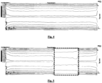
- Fig. 4 there is disclosed an example of a normal current distribution in a state of the art cell.
- Fig. 5 discloses the current distribution after individual cathodes in the cathode panel has been selectively modified, according to Fig. 1 .
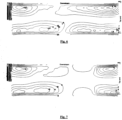
- Fig. 7 the corresponding force components are disclosed for a selectively modified cell according to Fig. 1 . It can clearly be seen that the force components are lower in the region of which the cathode current distribution is modified by the reduction of horizontal current components.
- modelled metal heights are disclosed for a normal cell.
- Fig 9 discloses the modelled metal heights for a modified cell according to that of Fig. 1 .
- the variation of metal height is considerably higher for the unmodified cell with its lowest height at the at the right hand side, being considerably lower than at the left hand side.
- the total metal heaving is lower and the metal is more evenly distributed between left and right side of the cell.
- measured metal heights for normal cells are disclosed.
- the y-position of the upstream measurement points are given by the midplane between the lower end of the cell and the cell centre (I-I) in Fig. 1 , as indicated by the thin dotted line marked US (Upstream).
- the y-position of the downstream measurement points are given by the midplane between the lower end of the cell and the cell centre (I-I) in Fig. 1 , as indicated by the thin dotted line marked DS (Downstream).
- the x-position for all measurement point increases monotonically from measurement point 1 to 5 starting from the left side of the cell to the right side of the cell.
- the actual cell measured on has not the same cathode block assembly as shown in Fig. 1 .
- the electrical conductivity of the modified cathode block assembly and its corresponding cathode bar connection to the bus bar system is kept unmodified as a whole.
- the electrical conductivity of the cathode bar connection can be reduced by:
- the electrical conductivity of the cathode bar connection can be increased by: b) Adding a copper extension or the similar
- the cathode block assembly When implementing the modifications in the cell, it is preferred to keep the total resistivity of the cathode block assembly together with its collector bar connection(s) constant.
- One alternative is to modify the collector bar connections at the unmodified positions to have the same resistance in all positions of the cathode panel.
- a reduced cathode collector bar resistivity in selected blocks will result in reduced horizontal current components (i y ) in the metal zone.
- the reduction in cathode collector bar resistivity can be compensated by increased resistivity of the corresponding cathode bar connection by increasing the resistivity of the flexibles (reduced cross section) connecting the bus bar system.
- the cathode bar connections for the rest of cathode block assemblies can be modified with better electrical conductivity, corresponding to that of the modified one.
- FIG. 13 there is disclosed a schematic top view of an electrolysis cell similar to that of Fig. 1 where the electrical conductivity of the cathode block section assemblies in position 1", 2" and 3" is increased according to method I, ii and iii respectively and where the flexibles have reduced electrical conductivity according to method a for modification of the cathode bar connection. The rest of the positions are unmodified.
- FIG. 15 there is disclosed a schematic top view of an electrolysis cell similar to that of Fig. 1 where the electrical conductivity of the cathode block section assemblies in pos 4" and 5" is decreased according to method iv and v respectively and where the cathode bar connection is modified according to method b. The rest of the positions are unmodified.
- a reduction in cathode flexible's cross section is adjusted to keep the resistivity in the cathode assembly constant.
- An alternative method for achieving the same is to increase the length of the electrical insulation between the cathode collector bar and the cathode block.
- the metal heaving and MHD stability for all possible modifications is calculated, but with only one modification for each calculation.
- the calculations are assisted by establishing a model of the actual electrolysis cell in computer based modelling program where each cathode block assembly or cathode block section assembly is represented.
- the modelling program is able to identify which cathode block assembly or cathode block section assembly that preferably should be modified.
- the most promising modification(-s) should be implemented in the cell.
- the cell can be built greenfield with the modification(-s) or brownfield as a part of ordinary re-lining maintenance. The most important steps are:
- cathode bars to be modified can also in an alternative be based on studying the force components and calculate the resulting metal heaving and MHD stability for several selected cases (trial and error).
- the method can be applied for cathode block assemblies or cathode block section assemblies comprising one, two or more cathode bars.
- collector bar insulation at selected cathodes clearly improves metal heaving and instability rate (IR) by reducing the forces that pushes excessive metal into one side of the cell. Improvements in cell operation are expected.
Landscapes
- Chemical & Material Sciences (AREA)
- Engineering & Computer Science (AREA)
- Chemical Kinetics & Catalysis (AREA)
- Electrochemistry (AREA)
- Materials Engineering (AREA)
- Metallurgy (AREA)
- Organic Chemistry (AREA)
- Electrolytic Production Of Metals (AREA)
Claims (15)
- Procédé permettant de réduire l'inégalité de patin métallique et d'optimiser la stabilité hydrodynamique de l'aimant (MHD) dans une cellule d'électrolyse du type Hall-Héroult destinée à la production d'aluminium, la cellule comportant des anodes en carbone précuites en suspension et un panneau cathodique comprenant plusieurs blocs cathodiques à base de carbone ayant une ou plusieurs barres de collecteur formant ainsi un ensemble de bloc cathodique, dans lequel ledit ensemble de bloc cathodique peut être constitué de plusieurs sections de bloc cathodique individuelles qui ensemble avec ses barres de collecteur cathodique forment des ensembles de section de bloc cathodique, lesdits ensembles de bloc cathodique ou ensembles de section de bloc cathodique étant reliés à un système de barres omnibus d'une ligne de cuves par l'intermédiaire de ses connexions de barres cathodiques, la cellule comportant en outre un patin métallique qui repose sur le panneau cathodique et un bain électrolytique situé entre ledit patin métallique et les anodes, dans lequel l'inégalité du patin métallique détecté par des mesures ou des calculs,
caractérisé en ce que
un modèle de la cellule d'électrolyse est établi dans un programme de modélisation informatisé dans lequel chaque ensemble de bloc cathodique ou chaque ensemble de section de bloc cathodique est représenté, le programme de modélisation étant capable de calculer le soulèvement du métal et la stabilité MHD pour toutes les modifications possibles pour chaque ensemble de bloc cathodiques ou chaque ensemble de section de bloc cathodique, les modifications possibles étant au moins l'une parmi : l'augmentation de la conductivité électrique dans l'ensemble de bloc cathodique, la diminution de la conductivité électrique dans l'ensemble de bloc cathodique, l'augmentation de la conductivité électrique de la collection de barre cathodique, et la réduction de la conductivité électrique de la connexion de barre cathodique, pour identifier quel ensemble de bloc cathodique ou quel ensemble de section de bloc cathodique devrait être préférablement modifié, dans lequel au moins l'une des modifications est mise en œuvre dans la cellule par changement de manière sélective de la distribution de courant électrique dans les ensembles de bloc cathodique individuels ou dans les ensembles de section de bloc cathodique de telle sorte que les canaux de courant électrique locaux et de manière correspondante les forces locales dans le patin métallique situé au-dessus du panneau cathodique sont modifiés afin de réduire l'inégalité du patin métallique et pour optimiser la stabilité MHD générale de la cellule. - Procédé selon la revendication 1, caractérisé en ce que la quantité totale de courant électrique extrait par chaque ensemble de bloc cathodique ou par chaque ensemble de section de bloc cathodique est maintenue constante au moyen de ladite modification.
- Procédé selon la revendication 1, caractérisé en ce que la quantité totale de courant électrique extrait par chaque ensemble de blocs cathodiques ou chaque ensemble de section de bloc cathodique est maintenue constante au moyen de ladite modification, dans lequel les connexions de barre cathodique (a, b) au système de barres omnibus sont modifiées.
- Procédé selon la revendication 1, caractérisé en ce que la qualité du bloc cathodique ou de la section de bloc cathodique est modifiée en ce que la conductivité électrique du bloc à base de carbone augmente en direction du centre de la cellule.
- Procédé selon la revendication 1, caractérisé en ce que la conductivité électrique des barres de collecteur cathodique est augmentée, par exemple au moyen de l'utilisation sélective d'inserts de Cu.
- Procédé selon la revendication 1, caractérisé en ce que la dimension des barres de collecteur cathodique est augmentée pour réduire la chute de tension.
- Procédé selon la revendication 1, caractérisé en ce que la conductivité électrique du bloc à base de carbone de la section de bloc est réduite en isolant partiellement de manière électrique les barres de collecteur cathodique du bloc à base de carbone.
- Procédé selon la revendication 1, caractérisé en ce que la conductivité électrique du bloc de carbone dans un ensemble de bloc de cathode modifié est réduite.
- Procédé selon l'une quelconque des revendications 4 à 6, caractérisé en ce que dans un ensemble de bloc de cathode modifié, la conductivité électrique de la connexion de barre cathodique est réduite.
- Procédé selon l'une quelconque des revendications 4 à 6, caractérisé en ce que dans un ensemble de bloc cathodique non modifié, la conductivité électrique de la connexion de barre cathodique est augmentée.
- Procédé selon l'une quelconque des revendications 7 à 8, caractérisé en ce que dans l'ensemble de bloc cathodique modifié, la conductivité électrique de la connexion de barre cathodique est augmentée.
- Procédé selon l'une quelconque des revendications 7 à 8, caractérisé en ce que dans un ensemble de bloc cathodique non modifié, la conductivité électrique de la connexion de barre cathodique est réduite.
- Procédé selon la revendication 1, caractérisé en ce que la résistance du panneau cathodique est maintenue inchangée dans son ensemble en appliquant des combinaisons d'un ou de plusieurs procédés dans les revendications 4 à 8 et à la fois en a et b, dans lequela) la réduction de la conductivité électrique de la connexion de barre cathodique par réduction de la section transversale d'un flexible en cuivre ou similaire ;b) l'augmentation de la conductivité électrique de la connexion de barre cathodique par l'ajout d'une extension de cuivre ou similaire.
- Procédé selon la revendication 1, dans lequel la sélection des barres cathodiques à modifier dans l'opération de modélisation informatisée est effectuée selon les étapes suivantes consistant à :• commencer avec une conception de cathode normale pour toutes les positions de cathode allant de 1 à n, le nombre n étant le nombre de blocs cathodiques ou de sections de bloc cathodique,• la conception correspondante de barres de cathode doit être définie, par exemple étant constituée de deux barres pour un bloc de cathode typique,• modifier la barre cathodique 1 en position 1 avec une résistivité de barre cathodique réduite et éventuellement une augmentation correspondante en terme de résistivité flexible cathodique pour obtenir la même résistivité globale qu'un bloc cathodique normal ou qu'une section de bloc cathodique, calculer le soulèvement du métal et la stabilité MHD et stocker les résultats,• recommencer avec une conception de cathodique normale pour toutes les positions cathodiques restantes allant de 2 à n,• modifier la barre cathodique 2 en position 1 avec une résistivité de barre cathodique réduite et éventuellement une augmentation correspondante en terme de résistivité flexible cathodique pour atteindre la même résistivité globale qu'un bloc cathodique normal ou qu'une section de bloc cathodique, calculer le soulèvement du métal et la stabilité MHD et stocker les résultats,• répétez les étapes ci-dessus pour toutes les barres et les positions cathodiques,• les résultats obtenus sont alors utilisés pour trouver les combinaisons prometteuses de blocs cathodiques modifiés et non modifiés,• les combinaisons prometteuses sont ensuite testées en calculant le soulèvement du métal et la stabilité MHD,• après quoi au moins une modification est mise en œuvre dans la cellule de production.
- Procédé selon la revendication 10, caractérisé en ce qu'un modèle simplifié de la cellule comprend de nombreux ensembles de bloc cathodique représentant une position.
Applications Claiming Priority (2)
| Application Number | Priority Date | Filing Date | Title |
|---|---|---|---|
| NO20141572A NO20141572A1 (no) | 2014-12-23 | 2014-12-23 | En modifisert elektrolysecelle og en fremgangsmåte for modifisering av samme |
| PCT/NO2015/000030 WO2016105204A1 (fr) | 2014-12-23 | 2015-12-22 | Cellule d'électrolyse modifiée et procédé permettant de modifier cette dernière |
Publications (3)
| Publication Number | Publication Date |
|---|---|
| EP3237655A1 EP3237655A1 (fr) | 2017-11-01 |
| EP3237655A4 EP3237655A4 (fr) | 2018-09-05 |
| EP3237655B1 true EP3237655B1 (fr) | 2023-02-08 |
Family
ID=56151095
Family Applications (1)
| Application Number | Title | Priority Date | Filing Date |
|---|---|---|---|
| EP15873710.6A Active EP3237655B1 (fr) | 2014-12-23 | 2015-12-22 | Cellule d'électrolyse modifiée et procédé permettant de modifier cette dernière |
Country Status (10)
| Country | Link |
|---|---|
| US (1) | US10689770B2 (fr) |
| EP (1) | EP3237655B1 (fr) |
| CN (1) | CN107109675B (fr) |
| AU (1) | AU2015367913B2 (fr) |
| BR (1) | BR112017013384B1 (fr) |
| CA (1) | CA2970605C (fr) |
| EA (1) | EA037336B1 (fr) |
| NO (1) | NO20141572A1 (fr) |
| NZ (1) | NZ732578A (fr) |
| WO (1) | WO2016105204A1 (fr) |
Families Citing this family (4)
| Publication number | Priority date | Publication date | Assignee | Title |
|---|---|---|---|---|
| EP3491175A1 (fr) * | 2016-07-26 | 2019-06-05 | COBEX GmbH | Ensemble cathode pour la production d'aluminium |
| US11286574B2 (en) | 2016-07-26 | 2022-03-29 | Tokai Cobex Gmbh | Cathode current collector/connector for a Hall-Heroult cell |
| NO20180369A1 (en) * | 2018-03-14 | 2019-09-16 | Norsk Hydro As | Cathode elements for a Hall-Héroult cell for aluminium production and a cell of this type having such elements installed |
| CN116820155B (zh) * | 2023-06-02 | 2025-11-28 | 桂林电子科技大学 | 一种基于大数据的稀土电解槽温测控方法 |
Family Cites Families (13)
| Publication number | Priority date | Publication date | Assignee | Title |
|---|---|---|---|---|
| US3385778A (en) * | 1964-10-21 | 1968-05-28 | Aluminum Co Of America | Current collecting method and apparatus for aluminum reduction cells |
| CA968744A (en) * | 1970-12-12 | 1975-06-03 | Kurt Lauer | Cathode for the winning of aluminum |
| NO139829C (no) | 1977-10-19 | 1979-05-16 | Ardal Og Sunndal Verk | Anordning for kompensering av skadelig magnetisk paavirkning mellom to eller flere rekker av tverrstilte elektrolyseovner for smelteelektrolytisk fremstilling av aluminium |
| NO140602C (no) | 1978-01-11 | 1979-10-03 | Ardal Og Sunndal Verk | Anordning for kompensering av skadelig magnetisk paavirkning paa tverrstilte ovner i en ovnsrekke fra en eller flere naborekker, i anlegg for smelte-elektrolytisk fremstilling av aluminium |
| EP0016728A1 (fr) * | 1979-03-23 | 1980-10-01 | Schweizerische Aluminium AG | Cellule électrolytique pour la production d'aluminium par électrolyse ignée de sels d'aluminium |
| NO166657C (no) | 1988-11-28 | 1991-08-21 | Norsk Hydro As | Skinnearrangement for store tverrstilte elektrolyseovner. |
| US6231745B1 (en) * | 1999-10-13 | 2001-05-15 | Alcoa Inc. | Cathode collector bar |
| EP1927679B1 (fr) | 2006-11-22 | 2017-01-11 | Rio Tinto Alcan International Limited | Cellule d'électrolyse destinée à la production d'aluminium avec un moyen pour la diminution de la chute de tension |
| CN201162052Y (zh) * | 2008-03-04 | 2008-12-10 | 东北大学设计研究院(有限公司) | 一种组合型铝电解槽阴极 |
| EA021620B1 (ru) * | 2009-09-07 | 2015-07-30 | Норск Хюдро Аса | Конструкция катодного кожуха |
| DE102011076302A1 (de) * | 2011-05-23 | 2013-01-03 | Sgl Carbon Se | Elektrolysezelle und Kathode mit unregelmäßiger Oberflächenprofilierung |
| CN102234820B (zh) * | 2011-08-04 | 2013-03-20 | 中国铝业股份有限公司 | 一种减少铝电解槽铝液水平电流的方法 |
| US8795507B2 (en) * | 2011-08-05 | 2014-08-05 | Alcoa Inc. | Apparatus and method for improving magneto-hydrodynamics stability and reducing energy consumption for aluminum reduction cells |
-
2014
- 2014-12-23 NO NO20141572A patent/NO20141572A1/no unknown
-
2015
- 2015-12-22 AU AU2015367913A patent/AU2015367913B2/en active Active
- 2015-12-22 WO PCT/NO2015/000030 patent/WO2016105204A1/fr not_active Ceased
- 2015-12-22 US US15/537,957 patent/US10689770B2/en active Active
- 2015-12-22 CN CN201580070551.8A patent/CN107109675B/zh active Active
- 2015-12-22 BR BR112017013384-9A patent/BR112017013384B1/pt active IP Right Grant
- 2015-12-22 EA EA201791438A patent/EA037336B1/ru unknown
- 2015-12-22 EP EP15873710.6A patent/EP3237655B1/fr active Active
- 2015-12-22 CA CA2970605A patent/CA2970605C/fr active Active
- 2015-12-22 NZ NZ732578A patent/NZ732578A/en unknown
Also Published As
| Publication number | Publication date |
|---|---|
| NO20141572A1 (no) | 2016-06-24 |
| AU2015367913A1 (en) | 2017-06-29 |
| EA201791438A1 (ru) | 2017-11-30 |
| EP3237655A1 (fr) | 2017-11-01 |
| CA2970605C (fr) | 2022-05-10 |
| CN107109675B (zh) | 2022-11-22 |
| WO2016105204A1 (fr) | 2016-06-30 |
| EA037336B1 (ru) | 2021-03-15 |
| BR112017013384A2 (pt) | 2018-03-06 |
| US20170350028A1 (en) | 2017-12-07 |
| BR112017013384B1 (pt) | 2022-02-01 |
| NZ732578A (en) | 2018-02-23 |
| CN107109675A (zh) | 2017-08-29 |
| US10689770B2 (en) | 2020-06-23 |
| AU2015367913B2 (en) | 2020-04-16 |
| EP3237655A4 (fr) | 2018-09-05 |
| CA2970605A1 (fr) | 2016-06-30 |
Similar Documents
| Publication | Publication Date | Title |
|---|---|---|
| EP3237655B1 (fr) | Cellule d'électrolyse modifiée et procédé permettant de modifier cette dernière | |
| RU2449058C2 (ru) | Электролизер для производства алюминия, содержащий средства для уменьшения падения напряжения | |
| AU2008318268B2 (en) | Composite collector bar | |
| RU2723867C1 (ru) | Катодный токоотвод/соединитель для электролизера холла-эру | |
| EP1812626B1 (fr) | Procede de connexion electrique et de compensation magnetique de cuves d'electrolyse d'aluminium, et systeme associe | |
| CN105603457B (zh) | 一种超大型铝电解槽的阴极母线配置方法 | |
| RU2548352C2 (ru) | Ошиновка алюминиевых электролизеров продольного расположения | |
| CN110392750B (zh) | 用于铝电解槽系列的模块化母线系统 | |
| EP2150639B1 (fr) | Cellules d'électrolyse branchées en série et leur procédé d'exploitation | |
| WO2018234946A1 (fr) | Installation d'électrolyse utilisant le procédé hall-héroult, à compensation du champ magnétique vertical | |
| EP2650404B1 (fr) | Cellule d'électrolyse, en particulier pour la production d'aluminium | |
| CA2869983C (fr) | Cellule d'electrolyse, en particulier pour la production d'aluminium |
Legal Events
| Date | Code | Title | Description |
|---|---|---|---|
| STAA | Information on the status of an ep patent application or granted ep patent |
Free format text: STATUS: THE INTERNATIONAL PUBLICATION HAS BEEN MADE |
|
| PUAI | Public reference made under article 153(3) epc to a published international application that has entered the european phase |
Free format text: ORIGINAL CODE: 0009012 |
|
| STAA | Information on the status of an ep patent application or granted ep patent |
Free format text: STATUS: REQUEST FOR EXAMINATION WAS MADE |
|
| 17P | Request for examination filed |
Effective date: 20170724 |
|
| AK | Designated contracting states |
Kind code of ref document: A1 Designated state(s): AL AT BE BG CH CY CZ DE DK EE ES FI FR GB GR HR HU IE IS IT LI LT LU LV MC MK MT NL NO PL PT RO RS SE SI SK SM TR |
|
| AX | Request for extension of the european patent |
Extension state: BA ME |
|
| DAV | Request for validation of the european patent (deleted) | ||
| DAX | Request for extension of the european patent (deleted) | ||
| A4 | Supplementary search report drawn up and despatched |
Effective date: 20180806 |
|
| RIC1 | Information provided on ipc code assigned before grant |
Ipc: C25C 3/12 20060101ALI20180731BHEP Ipc: C25C 3/16 20060101ALI20180731BHEP Ipc: C25C 3/08 20060101AFI20180731BHEP Ipc: C25C 3/10 20060101ALI20180731BHEP Ipc: C25C 3/20 20060101ALI20180731BHEP |
|
| STAA | Information on the status of an ep patent application or granted ep patent |
Free format text: STATUS: EXAMINATION IS IN PROGRESS |
|
| 17Q | First examination report despatched |
Effective date: 20200108 |
|
| GRAP | Despatch of communication of intention to grant a patent |
Free format text: ORIGINAL CODE: EPIDOSNIGR1 |
|
| STAA | Information on the status of an ep patent application or granted ep patent |
Free format text: STATUS: GRANT OF PATENT IS INTENDED |
|
| INTG | Intention to grant announced |
Effective date: 20221017 |
|
| GRAS | Grant fee paid |
Free format text: ORIGINAL CODE: EPIDOSNIGR3 |
|
| GRAA | (expected) grant |
Free format text: ORIGINAL CODE: 0009210 |
|
| STAA | Information on the status of an ep patent application or granted ep patent |
Free format text: STATUS: THE PATENT HAS BEEN GRANTED |
|
| AK | Designated contracting states |
Kind code of ref document: B1 Designated state(s): AL AT BE BG CH CY CZ DE DK EE ES FI FR GB GR HR HU IE IS IT LI LT LU LV MC MK MT NL NO PL PT RO RS SE SI SK SM TR |
|
| REG | Reference to a national code |
Ref country code: GB Ref legal event code: FG4D |
|
| REG | Reference to a national code |
Ref country code: CH Ref legal event code: EP Ref country code: AT Ref legal event code: REF Ref document number: 1547498 Country of ref document: AT Kind code of ref document: T Effective date: 20230215 |
|
| REG | Reference to a national code |
Ref country code: IE Ref legal event code: FG4D |
|
| REG | Reference to a national code |
Ref country code: DE Ref legal event code: R096 Ref document number: 602015082486 Country of ref document: DE |
|
| REG | Reference to a national code |
Ref country code: SK Ref legal event code: T3 Ref document number: E 41440 Country of ref document: SK |
|
| REG | Reference to a national code |
Ref country code: NO Ref legal event code: T2 Effective date: 20230208 |
|
| REG | Reference to a national code |
Ref country code: LT Ref legal event code: MG9D |
|
| REG | Reference to a national code |
Ref country code: NL Ref legal event code: MP Effective date: 20230208 |
|
| P01 | Opt-out of the competence of the unified patent court (upc) registered |
Effective date: 20230607 |
|
| REG | Reference to a national code |
Ref country code: AT Ref legal event code: MK05 Ref document number: 1547498 Country of ref document: AT Kind code of ref document: T Effective date: 20230208 |
|
| PG25 | Lapsed in a contracting state [announced via postgrant information from national office to epo] |
Ref country code: RS Free format text: LAPSE BECAUSE OF FAILURE TO SUBMIT A TRANSLATION OF THE DESCRIPTION OR TO PAY THE FEE WITHIN THE PRESCRIBED TIME-LIMIT Effective date: 20230208 Ref country code: PT Free format text: LAPSE BECAUSE OF FAILURE TO SUBMIT A TRANSLATION OF THE DESCRIPTION OR TO PAY THE FEE WITHIN THE PRESCRIBED TIME-LIMIT Effective date: 20230609 Ref country code: NL Free format text: LAPSE BECAUSE OF FAILURE TO SUBMIT A TRANSLATION OF THE DESCRIPTION OR TO PAY THE FEE WITHIN THE PRESCRIBED TIME-LIMIT Effective date: 20230208 Ref country code: LV Free format text: LAPSE BECAUSE OF FAILURE TO SUBMIT A TRANSLATION OF THE DESCRIPTION OR TO PAY THE FEE WITHIN THE PRESCRIBED TIME-LIMIT Effective date: 20230208 Ref country code: LT Free format text: LAPSE BECAUSE OF FAILURE TO SUBMIT A TRANSLATION OF THE DESCRIPTION OR TO PAY THE FEE WITHIN THE PRESCRIBED TIME-LIMIT Effective date: 20230208 Ref country code: HR Free format text: LAPSE BECAUSE OF FAILURE TO SUBMIT A TRANSLATION OF THE DESCRIPTION OR TO PAY THE FEE WITHIN THE PRESCRIBED TIME-LIMIT Effective date: 20230208 Ref country code: ES Free format text: LAPSE BECAUSE OF FAILURE TO SUBMIT A TRANSLATION OF THE DESCRIPTION OR TO PAY THE FEE WITHIN THE PRESCRIBED TIME-LIMIT Effective date: 20230208 Ref country code: AT Free format text: LAPSE BECAUSE OF FAILURE TO SUBMIT A TRANSLATION OF THE DESCRIPTION OR TO PAY THE FEE WITHIN THE PRESCRIBED TIME-LIMIT Effective date: 20230208 |
|
| PG25 | Lapsed in a contracting state [announced via postgrant information from national office to epo] |
Ref country code: SE Free format text: LAPSE BECAUSE OF FAILURE TO SUBMIT A TRANSLATION OF THE DESCRIPTION OR TO PAY THE FEE WITHIN THE PRESCRIBED TIME-LIMIT Effective date: 20230208 Ref country code: PL Free format text: LAPSE BECAUSE OF FAILURE TO SUBMIT A TRANSLATION OF THE DESCRIPTION OR TO PAY THE FEE WITHIN THE PRESCRIBED TIME-LIMIT Effective date: 20230208 Ref country code: GR Free format text: LAPSE BECAUSE OF FAILURE TO SUBMIT A TRANSLATION OF THE DESCRIPTION OR TO PAY THE FEE WITHIN THE PRESCRIBED TIME-LIMIT Effective date: 20230509 Ref country code: FI Free format text: LAPSE BECAUSE OF FAILURE TO SUBMIT A TRANSLATION OF THE DESCRIPTION OR TO PAY THE FEE WITHIN THE PRESCRIBED TIME-LIMIT Effective date: 20230208 |
|
| PG25 | Lapsed in a contracting state [announced via postgrant information from national office to epo] |
Ref country code: SM Free format text: LAPSE BECAUSE OF FAILURE TO SUBMIT A TRANSLATION OF THE DESCRIPTION OR TO PAY THE FEE WITHIN THE PRESCRIBED TIME-LIMIT Effective date: 20230208 Ref country code: RO Free format text: LAPSE BECAUSE OF FAILURE TO SUBMIT A TRANSLATION OF THE DESCRIPTION OR TO PAY THE FEE WITHIN THE PRESCRIBED TIME-LIMIT Effective date: 20230208 Ref country code: EE Free format text: LAPSE BECAUSE OF FAILURE TO SUBMIT A TRANSLATION OF THE DESCRIPTION OR TO PAY THE FEE WITHIN THE PRESCRIBED TIME-LIMIT Effective date: 20230208 Ref country code: DK Free format text: LAPSE BECAUSE OF FAILURE TO SUBMIT A TRANSLATION OF THE DESCRIPTION OR TO PAY THE FEE WITHIN THE PRESCRIBED TIME-LIMIT Effective date: 20230208 Ref country code: CZ Free format text: LAPSE BECAUSE OF FAILURE TO SUBMIT A TRANSLATION OF THE DESCRIPTION OR TO PAY THE FEE WITHIN THE PRESCRIBED TIME-LIMIT Effective date: 20230208 |
|
| REG | Reference to a national code |
Ref country code: DE Ref legal event code: R097 Ref document number: 602015082486 Country of ref document: DE |
|
| PLBE | No opposition filed within time limit |
Free format text: ORIGINAL CODE: 0009261 |
|
| STAA | Information on the status of an ep patent application or granted ep patent |
Free format text: STATUS: NO OPPOSITION FILED WITHIN TIME LIMIT |
|
| 26N | No opposition filed |
Effective date: 20231109 |
|
| PG25 | Lapsed in a contracting state [announced via postgrant information from national office to epo] |
Ref country code: SI Free format text: LAPSE BECAUSE OF FAILURE TO SUBMIT A TRANSLATION OF THE DESCRIPTION OR TO PAY THE FEE WITHIN THE PRESCRIBED TIME-LIMIT Effective date: 20230208 |
|
| PG25 | Lapsed in a contracting state [announced via postgrant information from national office to epo] |
Ref country code: IT Free format text: LAPSE BECAUSE OF FAILURE TO SUBMIT A TRANSLATION OF THE DESCRIPTION OR TO PAY THE FEE WITHIN THE PRESCRIBED TIME-LIMIT Effective date: 20230208 |
|
| REG | Reference to a national code |
Ref country code: CH Ref legal event code: PL |
|
| PG25 | Lapsed in a contracting state [announced via postgrant information from national office to epo] |
Ref country code: LU Free format text: LAPSE BECAUSE OF NON-PAYMENT OF DUE FEES Effective date: 20231222 |
|
| PG25 | Lapsed in a contracting state [announced via postgrant information from national office to epo] |
Ref country code: MC Free format text: LAPSE BECAUSE OF FAILURE TO SUBMIT A TRANSLATION OF THE DESCRIPTION OR TO PAY THE FEE WITHIN THE PRESCRIBED TIME-LIMIT Effective date: 20230208 |
|
| GBPC | Gb: european patent ceased through non-payment of renewal fee |
Effective date: 20231222 |
|
| REG | Reference to a national code |
Ref country code: BE Ref legal event code: MM Effective date: 20231231 |
|
| PG25 | Lapsed in a contracting state [announced via postgrant information from national office to epo] |
Ref country code: MC Free format text: LAPSE BECAUSE OF FAILURE TO SUBMIT A TRANSLATION OF THE DESCRIPTION OR TO PAY THE FEE WITHIN THE PRESCRIBED TIME-LIMIT Effective date: 20230208 Ref country code: LU Free format text: LAPSE BECAUSE OF NON-PAYMENT OF DUE FEES Effective date: 20231222 |
|
| REG | Reference to a national code |
Ref country code: IE Ref legal event code: MM4A |
|
| PG25 | Lapsed in a contracting state [announced via postgrant information from national office to epo] |
Ref country code: IE Free format text: LAPSE BECAUSE OF NON-PAYMENT OF DUE FEES Effective date: 20231222 |
|
| PG25 | Lapsed in a contracting state [announced via postgrant information from national office to epo] |
Ref country code: GB Free format text: LAPSE BECAUSE OF NON-PAYMENT OF DUE FEES Effective date: 20231222 |
|
| PG25 | Lapsed in a contracting state [announced via postgrant information from national office to epo] |
Ref country code: BE Free format text: LAPSE BECAUSE OF NON-PAYMENT OF DUE FEES Effective date: 20231231 |
|
| PG25 | Lapsed in a contracting state [announced via postgrant information from national office to epo] |
Ref country code: CH Free format text: LAPSE BECAUSE OF NON-PAYMENT OF DUE FEES Effective date: 20231231 |
|
| PG25 | Lapsed in a contracting state [announced via postgrant information from national office to epo] |
Ref country code: IE Free format text: LAPSE BECAUSE OF NON-PAYMENT OF DUE FEES Effective date: 20231222 Ref country code: GB Free format text: LAPSE BECAUSE OF NON-PAYMENT OF DUE FEES Effective date: 20231222 Ref country code: CH Free format text: LAPSE BECAUSE OF NON-PAYMENT OF DUE FEES Effective date: 20231231 Ref country code: BE Free format text: LAPSE BECAUSE OF NON-PAYMENT OF DUE FEES Effective date: 20231231 |
|
| PG25 | Lapsed in a contracting state [announced via postgrant information from national office to epo] |
Ref country code: BG Free format text: LAPSE BECAUSE OF FAILURE TO SUBMIT A TRANSLATION OF THE DESCRIPTION OR TO PAY THE FEE WITHIN THE PRESCRIBED TIME-LIMIT Effective date: 20230208 |
|
| PG25 | Lapsed in a contracting state [announced via postgrant information from national office to epo] |
Ref country code: BG Free format text: LAPSE BECAUSE OF FAILURE TO SUBMIT A TRANSLATION OF THE DESCRIPTION OR TO PAY THE FEE WITHIN THE PRESCRIBED TIME-LIMIT Effective date: 20230208 |
|
| PG25 | Lapsed in a contracting state [announced via postgrant information from national office to epo] |
Ref country code: CY Free format text: LAPSE BECAUSE OF FAILURE TO SUBMIT A TRANSLATION OF THE DESCRIPTION OR TO PAY THE FEE WITHIN THE PRESCRIBED TIME-LIMIT; INVALID AB INITIO Effective date: 20151222 |
|
| PG25 | Lapsed in a contracting state [announced via postgrant information from national office to epo] |
Ref country code: HU Free format text: LAPSE BECAUSE OF FAILURE TO SUBMIT A TRANSLATION OF THE DESCRIPTION OR TO PAY THE FEE WITHIN THE PRESCRIBED TIME-LIMIT; INVALID AB INITIO Effective date: 20151222 |
|
| PG25 | Lapsed in a contracting state [announced via postgrant information from national office to epo] |
Ref country code: TR Free format text: LAPSE BECAUSE OF FAILURE TO SUBMIT A TRANSLATION OF THE DESCRIPTION OR TO PAY THE FEE WITHIN THE PRESCRIBED TIME-LIMIT Effective date: 20230208 |
|
| PGFP | Annual fee paid to national office [announced via postgrant information from national office to epo] |
Ref country code: IS Payment date: 20251211 Year of fee payment: 11 Ref country code: DE Payment date: 20251211 Year of fee payment: 11 |
|
| PGFP | Annual fee paid to national office [announced via postgrant information from national office to epo] |
Ref country code: FR Payment date: 20251229 Year of fee payment: 11 |
|
| PGFP | Annual fee paid to national office [announced via postgrant information from national office to epo] |
Ref country code: SK Payment date: 20251218 Year of fee payment: 11 |
|
| PGFP | Annual fee paid to national office [announced via postgrant information from national office to epo] |
Ref country code: NO Payment date: 20251230 Year of fee payment: 11 |