EP3237806B1 - Dispositif de remplissage pour un circuit de chauffage préssurisé - Google Patents
Dispositif de remplissage pour un circuit de chauffage préssurisé Download PDFInfo
- Publication number
- EP3237806B1 EP3237806B1 EP15817508.3A EP15817508A EP3237806B1 EP 3237806 B1 EP3237806 B1 EP 3237806B1 EP 15817508 A EP15817508 A EP 15817508A EP 3237806 B1 EP3237806 B1 EP 3237806B1
- Authority
- EP
- European Patent Office
- Prior art keywords
- valve
- spool
- fluid
- heating circuit
- port
- Prior art date
- Legal status (The legal status is an assumption and is not a legal conclusion. Google has not performed a legal analysis and makes no representation as to the accuracy of the status listed.)
- Active
Links
Images




Classifications
-
- F—MECHANICAL ENGINEERING; LIGHTING; HEATING; WEAPONS; BLASTING
- F24—HEATING; RANGES; VENTILATING
- F24D—DOMESTIC- OR SPACE-HEATING SYSTEMS, e.g. CENTRAL HEATING SYSTEMS; DOMESTIC HOT-WATER SUPPLY SYSTEMS; ELEMENTS OR COMPONENTS THEREFOR
- F24D3/00—Hot-water central heating systems
- F24D3/10—Feed-line arrangements, e.g. providing for heat-accumulator tanks, expansion tanks ; Hydraulic components of a central heating system
- F24D3/1083—Filling valves or arrangements for filling
-
- E—FIXED CONSTRUCTIONS
- E03—WATER SUPPLY; SEWERAGE
- E03C—DOMESTIC PLUMBING INSTALLATIONS FOR FRESH WATER OR WASTE WATER; SINKS
- E03C1/00—Domestic plumbing installations for fresh water or waste water; Sinks
- E03C1/02—Plumbing installations for fresh water
- E03C1/10—Devices for preventing contamination of drinking-water pipes, e.g. means for aerating self-closing flushing valves
-
- F—MECHANICAL ENGINEERING; LIGHTING; HEATING; WEAPONS; BLASTING
- F16—ENGINEERING ELEMENTS AND UNITS; GENERAL MEASURES FOR PRODUCING AND MAINTAINING EFFECTIVE FUNCTIONING OF MACHINES OR INSTALLATIONS; THERMAL INSULATION IN GENERAL
- F16L—PIPES; JOINTS OR FITTINGS FOR PIPES; SUPPORTS FOR PIPES, CABLES OR PROTECTIVE TUBING; MEANS FOR THERMAL INSULATION IN GENERAL
- F16L55/00—Devices or appurtenances for use in, or in connection with, pipes or pipe systems
- F16L55/10—Means for stopping flow in pipes or hoses
- F16L55/105—Closing devices introduced radially into the pipe or hose
-
- F—MECHANICAL ENGINEERING; LIGHTING; HEATING; WEAPONS; BLASTING
- F24—HEATING; RANGES; VENTILATING
- F24D—DOMESTIC- OR SPACE-HEATING SYSTEMS, e.g. CENTRAL HEATING SYSTEMS; DOMESTIC HOT-WATER SUPPLY SYSTEMS; ELEMENTS OR COMPONENTS THEREFOR
- F24D19/00—Details
- F24D19/08—Arrangements for drainage, venting or aerating
- F24D19/082—Arrangements for drainage, venting or aerating for water heating systems
- F24D19/088—Draining arrangements
-
- F—MECHANICAL ENGINEERING; LIGHTING; HEATING; WEAPONS; BLASTING
- F24—HEATING; RANGES; VENTILATING
- F24D—DOMESTIC- OR SPACE-HEATING SYSTEMS, e.g. CENTRAL HEATING SYSTEMS; DOMESTIC HOT-WATER SUPPLY SYSTEMS; ELEMENTS OR COMPONENTS THEREFOR
- F24D19/00—Details
- F24D19/10—Arrangement or mounting of control or safety devices
- F24D19/1006—Arrangement or mounting of control or safety devices for water heating systems
- F24D19/1009—Arrangement or mounting of control or safety devices for water heating systems for central heating
- F24D19/1015—Arrangement or mounting of control or safety devices for water heating systems for central heating using a valve or valves
-
- E—FIXED CONSTRUCTIONS
- E03—WATER SUPPLY; SEWERAGE
- E03C—DOMESTIC PLUMBING INSTALLATIONS FOR FRESH WATER OR WASTE WATER; SINKS
- E03C1/00—Domestic plumbing installations for fresh water or waste water; Sinks
- E03C1/02—Plumbing installations for fresh water
- E03C1/10—Devices for preventing contamination of drinking-water pipes, e.g. means for aerating self-closing flushing valves
- E03C1/104—Devices for preventing contamination of drinking-water pipes, e.g. means for aerating self-closing flushing valves using a single check valve
-
- E—FIXED CONSTRUCTIONS
- E03—WATER SUPPLY; SEWERAGE
- E03C—DOMESTIC PLUMBING INSTALLATIONS FOR FRESH WATER OR WASTE WATER; SINKS
- E03C1/00—Domestic plumbing installations for fresh water or waste water; Sinks
- E03C1/02—Plumbing installations for fresh water
- E03C1/10—Devices for preventing contamination of drinking-water pipes, e.g. means for aerating self-closing flushing valves
- E03C1/106—Devices for preventing contamination of drinking-water pipes, e.g. means for aerating self-closing flushing valves using two or more check valves
-
- F—MECHANICAL ENGINEERING; LIGHTING; HEATING; WEAPONS; BLASTING
- F24—HEATING; RANGES; VENTILATING
- F24D—DOMESTIC- OR SPACE-HEATING SYSTEMS, e.g. CENTRAL HEATING SYSTEMS; DOMESTIC HOT-WATER SUPPLY SYSTEMS; ELEMENTS OR COMPONENTS THEREFOR
- F24D2220/00—Components of central heating installations excluding heat sources
- F24D2220/02—Fluid distribution means
- F24D2220/0271—Valves
Definitions
- the present invention relates to a filling loop device for pressurised sealed central heating systems.
- a conventional pressurised heating systems includes a boiler or furnace 1 in line with heating circuit pipe 2.
- the boiler needs to be filled from a pressurised water source such as a mains water supply pipe 3.
- the mains water supply pipe 3 may be provided with an inlet valve 4 attached by a compression fitting.
- the inlet valve may be a stop or isolation valve.
- One inlet end of a plain hose 5 is connected by means of a BSP threaded coupling to the inlet valve 4.
- the heating circuit pipe 2 is provided with a spur on to which an outlet valve 6 is mounted by a compression coupling.
- the outlet valve is preferably a stop or isolation valve.
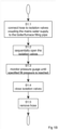
- the outlet end of the hose 5 is then connected to the outlet valve 6 by a threaded coupling (step S1 in figure 1B ).
- valves 4 and 6 are then opened (step S1.2) and water is allowed to flow into the heating circuit until a pressure gauge 7 indicates a specified circuit pressure is reached (S1.3).
- a check valve may be provided, preferably in one or more of the isolation valves, to prevent leakage of water back out of the pressurised circuit.
- valves 4 and 6 When the circuit is charged according to the system specifications the valves 4 and 6 should be closed (S1.4) and the hose 5 removed (S1.5) to ensure that there is no connection between the heating circuit 2 and mains supply pipe 3.
- the filling hose 5 should be left in close proximity to the boiler 1 to provide for subsequent system charging.
- boilers are damaged by an inexperienced or careless user leaving the filling device (filling loop) in place and the valves 4, 6 open, so over pressurising the system or allowing mains water to circulate within the heating circuit.
- Water in the heating circuit in accordance with good practice should be treated with anti-oxidising and anti-scaling agents. If the filling device is left in place untreated water circulates in the heating system accelerating corrosion and causing rapid and severe scaling with consequent premature failure of the boiler. Experience shows that the boiler failures can be sufficiently severe to require total replacement of the boiler.
- the prior art devices to prevent this situation are complex devices which admit water into the heating circuit on a periodic basis to maintain the pressure.
- GB2450086 discloses an apparatus for controlling the pressure of a heating fluid within a central heating system or for controlling the flow of heating fluid into a central heating system.
- the apparatus comprises an inlet, for connection to a supply of heating fluid, and an outlet, for connection to a heating system.
- a pressure sensor is arranged to sense the heating fluid pressure within the central heating system.
- a flow sensor is arranged to sense the volume of heating fluid flowing between the inlet and the outlet.
- a flow control valve controls the flow of heating fluid from the inlet to the outlet.
- the flow control valve is operatively connected to the pressure sensor and is arranged to open when the sensed pressure falls below a first predetermined pressure and close when the sensed pressure rises above a second predetermined pressure.
- the flow control valve is operatively connected to the flow sensor and is arranged to close once a predetermined volume of heating fluid has flowed.
- a self-bleeding radiator valve comprising a filter arranged to inhibit particulate matter from interfering with the operation of the valve is disclosed.
- a filtration device for a central heating system preferably comprising a magnetic particle filter, is also disclosed.
- This prior art device of GB2450086 provides a complex solution to the problem, comprising a pressure and/or flow sensor to control filling of the heating system by electronic means. As such it is over-complicated and costly for standard domestic use.
- US20060124078 discloses a water feed controller which can provide for the addition of a preset fixed amount of water to be added after a low water condition is removed.
- This system provides for a preset fixed amount of water to be added to a boiler above the amount which triggers the low water condition. This generally inhibits excess cycling from the boiler operating at its minimum safe water level as well as inhibiting overfilling of the boiler.
- a water feed controller which can measure the amount of water added over a prior predetermined period (such as 30 days) which serves as a floating window of time so that a leak or other condition resulting in overly frequent filling can be detected quickly.
- a water feed controller for a boiler comprising: electronics for monitoring the signal from a low water cut-off (LWCO); electronics for opening and closing a water path; and a processor; wherein when said electronics for monitoring detect a low water signal from said LWCO, said processor initiates opening of said water path to allow water to flow into said boiler; wherein said water path remains open until said LWCO ceases signalling a low water condition; and wherein said processor allows said water path to remain open after said LWCO ceases signalling said low water condition, so a preset fixed amount of water is added into said boiler after said LWCO ceases signalling said low water condition.
- LWCO low water cut-off
- a fluid source e.g. a mains water supply is connected to a fluid user system such as a combination boiler by means including a non-return valve unit, a flow regulator and pipework for connecting the valve unit and flow regulator.
- the non-return valve allows fluid flow to the fluid user system but prevents reverse fluid flow from the user system to the fluid source.
- the check valve unit may have an outlet portion permanently connected to the boiler and a conical inlet passage in which a flexible pipe may be held manually during top-up of the boiler.
- the unit may include two identical valve stems. This device is a standard filling loop device, without a fail-safe mechanism.
- WO9606308 discloses a filling loop device for a pressurized heating system comprising: means defining a fluid passage having an inlet port connectable to a fluid supply and an outlet port connectable to a heating system fluid circuit; and a dead man valve interposed in the passage between the inlet port and the outlet port, said dead man valve biased to a normally closed condition to shut off fluid flow through the channel in either direction when unattended, and manually operable to an open condition to permit fluid to flow from the inlet port to the outlet port.
- a filling device for a pressurised heating system as defined in claim 1.
- the fluid passage may be provided by a length of pipe, flexible hose or via a channel in a mono-block.
- the inlet and outlet ports may be provided by any conventional coupling including at least: threaded BSP and compression couplings.
- a push button valve may be vulnerable to jamming open by abusive users, for example by wrapping with tape, consequently actuators such as a spring biased twist grip or other less easily jammed configurations may be preferred.
- a one way or check valve is connected such that flow from the inlet to the outlet connector is allowed while the reverse flow is prevented.
- Single check valves may be vulnerable to reverse flow leakage to prevent which a double check valve may be provided.
- a second isolation valve may be connected to the check valve.
- a check valve and an isolation valve may be provided in the same housing.
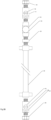
- the device comprises, connected in order along the flow pathway: a 15mm inlet compression to 8mm ball valve, an 8mm push button water valve, a 15mm to 8mm adapter, a 15mm flexible filling link comprising a metal braided hose and a 15mm double check ball valve.
- the device provides a means to fill a pressurised heating circuit from a pressurised water source such as a mains water supply, the device being connectable in place of a standard filling loop as known in the art.
- a pressurised water source such as a mains water supply
- the use of the push button valve in the fluid pathway means that it is impossible to leave the filling loop in place and open, so avoiding accidental damage to the heating boiler.
- the device can also include a pressure regulator pre-set to deliver fluid to the outlet at a pressure compatible with the operation of the boiler. This facilitates use by non-technical untrained or sight disabled users who may misread the pressure gauge and charge the heating system to excessive or inadequate pressure.
- An inlet valve 4 is coupled to a terminus of the mains water pipe 3 by means of an inlet connector 10.
- the inlet connector 10 is a conventional compression coupling; however other known forms of coupling including press fit, cement or solder may be employed.
- the coupling 10 couples an isolation valve 12 to the end of the mains water pipe 3.
- the second embodiment of the fill loop device is generally similar to the first and corresponding components are identified with similar numerals. Accordingly, only the differences will be described.
- the filling loop device includes a governor or pressure regulating valve 25 in series with the press button valve 14.
- the pressure regulating valve 25 is set to limit the maximum water supply pressure at the outlet 6 of the filling loop device to correspond to the specified maximum pressure for the boiler 1.
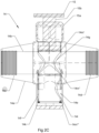
- a hollow nipple 14o may be formed on the spool chamber base in communication with the bore 14m to which a hose may be attached. This allows water flowing back into the press valve (from the right in figure 3C ), to flow through a drain port 14k formed in a bottom portion of the spool 14f and to drain out through the drain port 14j.
Landscapes
- Engineering & Computer Science (AREA)
- General Engineering & Computer Science (AREA)
- Mechanical Engineering (AREA)
- Chemical & Material Sciences (AREA)
- Thermal Sciences (AREA)
- Combustion & Propulsion (AREA)
- Physics & Mathematics (AREA)
- Health & Medical Sciences (AREA)
- Life Sciences & Earth Sciences (AREA)
- Hydrology & Water Resources (AREA)
- Public Health (AREA)
- Water Supply & Treatment (AREA)
- Safety Valves (AREA)
- Check Valves (AREA)
Claims (12)
- Dispositif de boucle de remplissage pour un système de chauffage sous pression comprenant :moyens comprenant une soupape à homme mort (14) définissant un passage de fluide (14b) ayant un orifice d'entrée (14c) pouvant être connecté à une alimentation en fluide et un orifice de sortie (14d) pouvant être connecté à un circuit de fluide de système de chauffage ; ladite vanne homme mort (14) polarisée vers un état normalement fermé pour couper l'écoulement de fluide à travers le passage de fluide (14b) dans les deux sens lorsqu'elle n'est pas surveillée, et pouvant être actionnée manuellement vers un état ouvert pour permettre au fluide de s'écouler de l'orifice d'entrée vers l'orifice de sortie ;ladite vanne homme mort (14) ayant :un boîtier (14a) fournissant le passage de fluide (14b) avec l'orifice d'entrée, l'orifice de sortie et une chambre de bobine (14e);une bobine (14f) logée de manière coulissante dans la chambre de bobine (14e), ladite bobine comprenant un passage traversant (14g) capable de faire communiquer l'orifice d'entrée (14c) et l'orifice de sortie (14d) pour un écoulement de fluide entre eux lorsqu'elle est actionnée manuellement, et des moyens de polarisation (14k) pour pousser la bobine (14f) vers l'état fermé de sorte qu'une partie inférieure (141) de la bobine (14f) obstrue le passage de fluide (14b) pour arrêter l'écoulement de fluide à travers l'orifice d'entrée (14c), etcaractérisé en ce qu'un passage de drainage est formé dans la partie inférieure de la bobine (14f) isolée du passage de fluide pour communiquer entre l'orifice de sortie et un orifice de drainage (14j) formé dans la partie inférieure de la chambre de bobine (14e) lorsque le moyen de polarisation (14k) déplace la bobine (14f) vers l'état fermé.
- Dispositif selon la revendication 1 comprenant une vanne régulatrice de pression (25) préréglée pour empêcher une surpression d'un système de chauffage.
- Dispositif selon la revendication 1 ou la revendication 2, dans lequel les moyens de sollicitation comprennent un ressort (14e) pour solliciter par ressort la bobine afin de fermer un passage de fluide à travers la vanne et un actionneur manuel pouvant être actionné pour déplacer la bobine en opposition à la force du ressort tout en étant actionné manuellement.
- Dispositif selon la revendication 3 dans lequel l'actionneur comprend un bouton-poussoir (15).
- Dispositif selon l'une quelconque des revendications 1 à 4, dans lequel l'orifice de drainage (14j) est formé dans une base de la chambre de bobine 14e.
- Dispositif selon l'une quelconque des revendications 1 à 5, dans lequel l'orifice de vidange (14j) est pourvu d'un raccord de tuyau.
- Dispositif selon la revendication 6, dans lequel le raccord de tuyau est un mamelon (14o).
- Dispositif selon l'une quelconque des revendications précédentes en combinaison avec une chaudière.
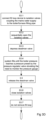
- Procédé de chargement d'une chaudière sous pression et d'un circuit de chauffage utilisant un dispositif de boucle de remplissage selon l'une quelconque des revendications 1 à 8 comprenant les étapes consistant à :fournir le canal de fluide entre une alimentation en eau du réseau et le circuit de chauffage sous pression, ledit canal de fluide comprenant une vanne d'arrêt à homme mort (14) ayant un actionneur à commande manuelle configuré pour fermer le canal lorsqu'il n'est pas actionné manuellement ;actionner manuellement la vanne homme mort pour permettre à l'eau de s'écouler du réseau d'alimentation vers le circuit de chauffage jusqu'à ce que le circuit de chauffage atteigne une pression de service spécifiée ;relâchement de l'actionneur de soupape d'homme mort pour fermer le canal caractérisé par l'étape du moyen de polarisation (14k) poussant la bobine (14f) de sorte que la partie inférieure de la bobine obstrue le passage de fluide (14b) pour fermer l'écoulement de fluide à travers l'orifice d'entrée (14c), et le passage de vidange communique entre l'orifice de sortie (14d) et l'orifice de vidange (14j).
- Procédé selon la revendication 9 comprenant le fait de laisser le canal de fluide en place après le chargement de la chaudière sous pression et du circuit de chauffage.
- Procédé selon l'une des revendications 9 ou 10, comprenant la fourniture d'un clapet anti-retour unidirectionnel dans le canal pour empêcher le reflux du circuit de chauffage vers l'alimentation secteur.
- Procédé selon l'une quelconque des revendications 9 à 11, comprenant la fourniture d'une vanne de régulation de pression dans le canal préréglée pour réguler la pression maximale de l'eau pouvant être délivrée au circuit de chauffage afin d'empêcher de charger le circuit de chauffage à une pression excessive dommageable.
Applications Claiming Priority (3)
| Application Number | Priority Date | Filing Date | Title |
|---|---|---|---|
| GBGB1411255.1A GB201411255D0 (en) | 2014-06-25 | 2014-06-25 | A filling device for a pressurised heating circuit |
| GB1421737.6A GB2527621B (en) | 2014-06-25 | 2014-12-08 | A filling loop device for a pressurised heating circuit |
| PCT/GB2015/053739 WO2016092279A1 (fr) | 2014-12-08 | 2015-12-07 | Dispositif de remplissage pour circuit de chauffage sous pression |
Publications (3)
| Publication Number | Publication Date |
|---|---|
| EP3237806A1 EP3237806A1 (fr) | 2017-11-01 |
| EP3237806B1 true EP3237806B1 (fr) | 2025-04-16 |
| EP3237806C0 EP3237806C0 (fr) | 2025-04-16 |
Family
ID=51410069
Family Applications (1)
| Application Number | Title | Priority Date | Filing Date |
|---|---|---|---|
| EP15817508.3A Active EP3237806B1 (fr) | 2014-06-25 | 2015-12-07 | Dispositif de remplissage pour un circuit de chauffage préssurisé |
Country Status (3)
| Country | Link |
|---|---|
| EP (1) | EP3237806B1 (fr) |
| CA (1) | CA2970198C (fr) |
| GB (2) | GB201411255D0 (fr) |
Families Citing this family (2)
| Publication number | Priority date | Publication date | Assignee | Title |
|---|---|---|---|---|
| TR202013269A1 (tr) * | 2020-08-21 | 2022-03-21 | Serdar Plastik Sanayi Ve Ticaret Anonim Sirketi | Disconnector (Geri Akış Önleyici) |
| EP4244538A1 (fr) * | 2020-10-12 | 2023-09-20 | Christopher Jepp | Injecteur d'inhibiteur et appareil à boucle de remplissage à fonctionnement à distance pour un système de chauffage |
Family Cites Families (4)
| Publication number | Priority date | Publication date | Assignee | Title |
|---|---|---|---|---|
| AU3263595A (en) * | 1994-08-23 | 1996-03-14 | Euro Innovations Limited | A valve |
| EP0801272A3 (fr) * | 1996-04-12 | 1998-10-14 | Joh. Vaillant GmbH u. Co. | Dispositif de remplissage pour chauffe-eau |
| AU2967397A (en) * | 1996-05-25 | 1998-01-05 | Euro Innovations Limited | Improvements in and relating to a valve |
| ES2404981B1 (es) * | 2011-11-15 | 2014-09-26 | Orkli, S.Coop. | Conjunto valvular adaptado para conectar una red de suministro de agua con un circuito primario |
-
2014
- 2014-06-25 GB GBGB1411255.1A patent/GB201411255D0/en not_active Ceased
- 2014-12-08 GB GB1421737.6A patent/GB2527621B/en active Active
-
2015
- 2015-12-07 CA CA2970198A patent/CA2970198C/fr active Active
- 2015-12-07 EP EP15817508.3A patent/EP3237806B1/fr active Active
Also Published As
| Publication number | Publication date |
|---|---|
| EP3237806C0 (fr) | 2025-04-16 |
| GB201411255D0 (en) | 2014-08-06 |
| GB2527621B (en) | 2017-04-19 |
| CA2970198C (fr) | 2023-08-08 |
| EP3237806A1 (fr) | 2017-11-01 |
| CA2970198A1 (fr) | 2016-06-16 |
| GB201421737D0 (en) | 2015-01-21 |
| GB2527621A (en) | 2015-12-30 |
Similar Documents
| Publication | Publication Date | Title |
|---|---|---|
| US20210071798A1 (en) | Filling Device for a Pressurized Heating Circuit | |
| CN103982686B (zh) | 具有简单泵启动的背压调节器 | |
| US20110073189A1 (en) | Water shut off with flow sensor emergency shut down | |
| CN104321492A (zh) | 限压阀和用于使用该限压阀测试回流防止器的替代方法 | |
| EP3309305B1 (fr) | Appareil antigel | |
| WO2015159040A1 (fr) | Dispositif de détection et de prévention de fuites d'eau | |
| CN103968117A (zh) | 具有集成的快速加压旁路阀的流体调节器 | |
| US8678025B2 (en) | Method and apparatus for controlling fluid pressure | |
| CA2970198C (fr) | Dispositif de remplissage pour circuit de chauffage sous pression | |
| US2635629A (en) | Excess flow cutoff valve | |
| US9964222B1 (en) | Failsafe hose | |
| US3746047A (en) | High or low pressure cutoff control valve | |
| US7434595B2 (en) | Safety valve assembly having set and reset mechanisms | |
| US3709241A (en) | Fill limiter, check and safety valve | |
| EP2980462B1 (fr) | Système de gestion de pression | |
| US2958219A (en) | Adapter for portable gage tester | |
| US6363963B1 (en) | Excess flow shutoff valve | |
| US7219688B2 (en) | Fluid control valve | |
| KR101590085B1 (ko) | 압력 계측기용 압력 누설 자동 차단 밸브 | |
| WO1989011611A1 (fr) | Clapet antirefouleur | |
| EP3693671B1 (fr) | Système de remplissage doté d'un dispositif d'actionnement thermique | |
| EP2975485B1 (fr) | Ensemble de vannes adapté pour réaliser la connexion automatique d'un réseau d'alimentation en eau à un circuit primaire | |
| RU2450191C2 (ru) | Спускной и предохранительный клапан | |
| GB2179425A (en) | A valve | |
| CA3078314C (fr) | Ensemble conduite de distribution de fluide avec ensemble clapet d'arret |
Legal Events
| Date | Code | Title | Description |
|---|---|---|---|
| STAA | Information on the status of an ep patent application or granted ep patent |
Free format text: STATUS: THE INTERNATIONAL PUBLICATION HAS BEEN MADE |
|
| PUAI | Public reference made under article 153(3) epc to a published international application that has entered the european phase |
Free format text: ORIGINAL CODE: 0009012 |
|
| STAA | Information on the status of an ep patent application or granted ep patent |
Free format text: STATUS: REQUEST FOR EXAMINATION WAS MADE |
|
| 17P | Request for examination filed |
Effective date: 20170704 |
|
| AK | Designated contracting states |
Kind code of ref document: A1 Designated state(s): AL AT BE BG CH CY CZ DE DK EE ES FI FR GB GR HR HU IE IS IT LI LT LU LV MC MK MT NL NO PL PT RO RS SE SI SK SM TR |
|
| AX | Request for extension of the european patent |
Extension state: BA ME |
|
| DAV | Request for validation of the european patent (deleted) | ||
| DAX | Request for extension of the european patent (deleted) | ||
| STAA | Information on the status of an ep patent application or granted ep patent |
Free format text: STATUS: EXAMINATION IS IN PROGRESS |
|
| 17Q | First examination report despatched |
Effective date: 20190708 |
|
| REG | Reference to a national code |
Ref country code: DE Ref legal event code: R079 Free format text: PREVIOUS MAIN CLASS: F24D0003100000 Ipc: F24D0019100000 Ref document number: 602015091458 Country of ref document: DE |
|
| GRAP | Despatch of communication of intention to grant a patent |
Free format text: ORIGINAL CODE: EPIDOSNIGR1 |
|
| STAA | Information on the status of an ep patent application or granted ep patent |
Free format text: STATUS: GRANT OF PATENT IS INTENDED |
|
| RIC1 | Information provided on ipc code assigned before grant |
Ipc: E03C 1/10 20060101ALI20241021BHEP Ipc: F24D 19/08 20060101ALI20241021BHEP Ipc: F24D 3/10 20060101ALI20241021BHEP Ipc: F16L 55/105 20060101ALI20241021BHEP Ipc: F24D 19/10 20060101AFI20241021BHEP |
|
| INTG | Intention to grant announced |
Effective date: 20241114 |
|
| GRAS | Grant fee paid |
Free format text: ORIGINAL CODE: EPIDOSNIGR3 |
|
| GRAA | (expected) grant |
Free format text: ORIGINAL CODE: 0009210 |
|
| STAA | Information on the status of an ep patent application or granted ep patent |
Free format text: STATUS: THE PATENT HAS BEEN GRANTED |
|
| AK | Designated contracting states |
Kind code of ref document: B1 Designated state(s): AL AT BE BG CH CY CZ DE DK EE ES FI FR GB GR HR HU IE IS IT LI LT LU LV MC MK MT NL NO PL PT RO RS SE SI SK SM TR |
|
| REG | Reference to a national code |
Ref country code: GB Ref legal event code: FG4D |
|
| REG | Reference to a national code |
Ref country code: CH Ref legal event code: EP Ref country code: DE Ref legal event code: R096 Ref document number: 602015091458 Country of ref document: DE |
|
| REG | Reference to a national code |
Ref country code: IE Ref legal event code: FG4D |
|
| U01 | Request for unitary effect filed |
Effective date: 20250515 |
|
| U07 | Unitary effect registered |
Designated state(s): AT BE BG DE DK EE FI FR IT LT LU LV MT NL PT RO SE SI Effective date: 20250521 |
|
| PG25 | Lapsed in a contracting state [announced via postgrant information from national office to epo] |
Ref country code: ES Free format text: LAPSE BECAUSE OF FAILURE TO SUBMIT A TRANSLATION OF THE DESCRIPTION OR TO PAY THE FEE WITHIN THE PRESCRIBED TIME-LIMIT Effective date: 20250416 |
|
| PG25 | Lapsed in a contracting state [announced via postgrant information from national office to epo] |
Ref country code: NO Free format text: LAPSE BECAUSE OF FAILURE TO SUBMIT A TRANSLATION OF THE DESCRIPTION OR TO PAY THE FEE WITHIN THE PRESCRIBED TIME-LIMIT Effective date: 20250716 Ref country code: GR Free format text: LAPSE BECAUSE OF FAILURE TO SUBMIT A TRANSLATION OF THE DESCRIPTION OR TO PAY THE FEE WITHIN THE PRESCRIBED TIME-LIMIT Effective date: 20250717 |
|
| PG25 | Lapsed in a contracting state [announced via postgrant information from national office to epo] |
Ref country code: PL Free format text: LAPSE BECAUSE OF FAILURE TO SUBMIT A TRANSLATION OF THE DESCRIPTION OR TO PAY THE FEE WITHIN THE PRESCRIBED TIME-LIMIT Effective date: 20250416 |
|
| PG25 | Lapsed in a contracting state [announced via postgrant information from national office to epo] |
Ref country code: HR Free format text: LAPSE BECAUSE OF FAILURE TO SUBMIT A TRANSLATION OF THE DESCRIPTION OR TO PAY THE FEE WITHIN THE PRESCRIBED TIME-LIMIT Effective date: 20250416 |
|
| PG25 | Lapsed in a contracting state [announced via postgrant information from national office to epo] |
Ref country code: RS Free format text: LAPSE BECAUSE OF FAILURE TO SUBMIT A TRANSLATION OF THE DESCRIPTION OR TO PAY THE FEE WITHIN THE PRESCRIBED TIME-LIMIT Effective date: 20250716 |
|
| PG25 | Lapsed in a contracting state [announced via postgrant information from national office to epo] |
Ref country code: IS Free format text: LAPSE BECAUSE OF FAILURE TO SUBMIT A TRANSLATION OF THE DESCRIPTION OR TO PAY THE FEE WITHIN THE PRESCRIBED TIME-LIMIT Effective date: 20250816 |
|
| PGFP | Annual fee paid to national office [announced via postgrant information from national office to epo] |
Ref country code: GB Payment date: 20251215 Year of fee payment: 11 |
|
| PG25 | Lapsed in a contracting state [announced via postgrant information from national office to epo] |
Ref country code: SM Free format text: LAPSE BECAUSE OF FAILURE TO SUBMIT A TRANSLATION OF THE DESCRIPTION OR TO PAY THE FEE WITHIN THE PRESCRIBED TIME-LIMIT Effective date: 20250416 |
|
| PG25 | Lapsed in a contracting state [announced via postgrant information from national office to epo] |
Ref country code: CZ Free format text: LAPSE BECAUSE OF FAILURE TO SUBMIT A TRANSLATION OF THE DESCRIPTION OR TO PAY THE FEE WITHIN THE PRESCRIBED TIME-LIMIT Effective date: 20250416 |
|
| U20 | Renewal fee for the european patent with unitary effect paid |
Year of fee payment: 11 Effective date: 20251215 |
|
| PG25 | Lapsed in a contracting state [announced via postgrant information from national office to epo] |
Ref country code: SK Free format text: LAPSE BECAUSE OF FAILURE TO SUBMIT A TRANSLATION OF THE DESCRIPTION OR TO PAY THE FEE WITHIN THE PRESCRIBED TIME-LIMIT Effective date: 20250416 |
|
| PLBE | No opposition filed within time limit |
Free format text: ORIGINAL CODE: 0009261 |
|
| STAA | Information on the status of an ep patent application or granted ep patent |
Free format text: STATUS: NO OPPOSITION FILED WITHIN TIME LIMIT |
|
| REG | Reference to a national code |
Ref country code: CH Ref legal event code: L10 Free format text: ST27 STATUS EVENT CODE: U-0-0-L10-L00 (AS PROVIDED BY THE NATIONAL OFFICE) Effective date: 20260225 |
|
| 26N | No opposition filed |
Effective date: 20260119 |