EP3237933B1 - Dispositif de detection de neutrons comprenant une feuille de conversion de neutron - Google Patents
Dispositif de detection de neutrons comprenant une feuille de conversion de neutron Download PDFInfo
- Publication number
- EP3237933B1 EP3237933B1 EP15816471.5A EP15816471A EP3237933B1 EP 3237933 B1 EP3237933 B1 EP 3237933B1 EP 15816471 A EP15816471 A EP 15816471A EP 3237933 B1 EP3237933 B1 EP 3237933B1
- Authority
- EP
- European Patent Office
- Prior art keywords
- neutron
- detecting device
- light
- detector
- conversion
- Prior art date
- Legal status (The legal status is an assumption and is not a legal conclusion. Google has not performed a legal analysis and makes no representation as to the accuracy of the status listed.)
- Active
Links
Images




Classifications
-
- G—PHYSICS
- G01—MEASURING; TESTING
- G01T—MEASUREMENT OF NUCLEAR OR X-RADIATION
- G01T3/00—Measuring neutron radiation
- G01T3/06—Measuring neutron radiation with scintillation detectors
-
- G—PHYSICS
- G01—MEASURING; TESTING
- G01T—MEASUREMENT OF NUCLEAR OR X-RADIATION
- G01T3/00—Measuring neutron radiation
- G01T3/06—Measuring neutron radiation with scintillation detectors
- G01T3/065—Spectrometry
-
- G—PHYSICS
- G21—NUCLEAR PHYSICS; NUCLEAR ENGINEERING
- G21K—HANDLING OF PARTICLES OR IONISING RADIATION NOT OTHERWISE PROVIDED FOR; IRRADIATION DEVICES; GAMMA RAY OR X-RAY MICROSCOPES
- G21K4/00—Conversion screens for the conversion of the spatial distribution of X-rays or particle radiation into visible images, e.g. fluoroscopic screens
- G21K2004/02—Conversion screens for the conversion of the spatial distribution of X-rays or particle radiation into visible images, e.g. fluoroscopic screens characterised by the external panel structure
-
- G—PHYSICS
- G21—NUCLEAR PHYSICS; NUCLEAR ENGINEERING
- G21K—HANDLING OF PARTICLES OR IONISING RADIATION NOT OTHERWISE PROVIDED FOR; IRRADIATION DEVICES; GAMMA RAY OR X-RAY MICROSCOPES
- G21K4/00—Conversion screens for the conversion of the spatial distribution of X-rays or particle radiation into visible images, e.g. fluoroscopic screens
- G21K2004/04—Conversion screens for the conversion of the spatial distribution of X-rays or particle radiation into visible images, e.g. fluoroscopic screens with an intermediate layer
-
- G—PHYSICS
- G21—NUCLEAR PHYSICS; NUCLEAR ENGINEERING
- G21K—HANDLING OF PARTICLES OR IONISING RADIATION NOT OTHERWISE PROVIDED FOR; IRRADIATION DEVICES; GAMMA RAY OR X-RAY MICROSCOPES
- G21K4/00—Conversion screens for the conversion of the spatial distribution of X-rays or particle radiation into visible images, e.g. fluoroscopic screens
- G21K2004/10—Conversion screens for the conversion of the spatial distribution of X-rays or particle radiation into visible images, e.g. fluoroscopic screens with a protective film
-
- G—PHYSICS
- G21—NUCLEAR PHYSICS; NUCLEAR ENGINEERING
- G21K—HANDLING OF PARTICLES OR IONISING RADIATION NOT OTHERWISE PROVIDED FOR; IRRADIATION DEVICES; GAMMA RAY OR X-RAY MICROSCOPES
- G21K4/00—Conversion screens for the conversion of the spatial distribution of X-rays or particle radiation into visible images, e.g. fluoroscopic screens
- G21K2004/12—Conversion screens for the conversion of the spatial distribution of X-rays or particle radiation into visible images, e.g. fluoroscopic screens with a support
Definitions
- the present invention relates to the technology of detecting neutrons.
- Document WO 2012/007734 A2 describes a radiation detector for neutrons and gamma rays with a conversion layer comprising a neutron capturing material and a phosphor, such that neutrons are converted into light signals. These light signals are then allowed to enter into a light guide, the light guide contains a wavelength shifter that absorbs the light and reemits at a longer wavelength. Reemission is isotropic, such that a fraction of the reemitted light can be transported via total internal reflection inside the light guide, until detected via a photoelectric converter, e.g. photomultiplier or similar device.
- the light guide may be a scintillator.
- Document CA 2 312 593 A1 describes a scintillator surrounded by a neutron conversion layer within a gamma radiation shield.
- the scintillator detects gamma rays of characteristic energy emitted by said conversion layer upon neutron capture.
- Document US 20050258373 A1 discloses a neutron detector technology based on ⁇ 10>B thin film conversion of neutrons and detection of neutron capture reaction products in a counter gas within a thin straw tube detector body is described.
- This neutron detector is based on gas-filled thin wall straw tubes, modified for the conversion of neutrons in a very thin coating, or layer, of ⁇ 10>B, applied for example as a sputter-coated film of ⁇ 10>B4C, that lines the interior, or inside of the straw tube surface; and the subsequent detection of the neutron reaction products in the counter gas.
- Document US 8,519,350 discloses surfaces or surface portions incorporated into gas-filled neutron detectors, which are coated with and/or composed of at least partially, neutron reactive material.
- the surfaces may be flat or curved fins or plates, foils, porous or filamentary material, or semi-solid material or aerogel.
- the incorporation of the extended surfaces coated with or composed of neutron reactive material increases the neutron detection efficiency of the gas-filled detectors over conventional coated designs.
- These surfaces or surface portions increase the amount of neutron reactive material present in the detector over conventional coated designs and, as a result, increase the neutron detection efficiency.
- the surfaces can be made of conductive, semiconductive or insulative materials. The surfaces are arranged such that they do not detrimentally detract from the main function of a gas-filled detector with particular attention to gas-filled proportional detectors.
- Document US2009/0078851 A1 describes a light sensitive type radiation detector, comprising a light emitting layer made of high-purity hexagonal boron nitride monocrystalline powder having a property of emitting far-UV light showing an emission peak at wavelength between 224 nm and 233 nm, especially at 227 nm, of the far-UV region and a photodetector for detecting light from the light emitting layer.
- a light sensitive type radiation detector comprising a light emitting layer made of high-purity hexagonal boron nitride monocrystalline powder having a property of emitting far-UV light showing an emission peak at wavelength between 224 nm and 233 nm, especially at 227 nm, of the far-UV region and a photodetector for detecting light from the light emitting layer.
- the light emitting layer is excited to emit light by the radiation and the photodetector detects the emitted light.
- Document EP2770342 A1 describes a neutron detector, the neutron detector comprising: a conversion layer comprising a mixture of a neutron absorbing material and a scintillation material; a light-guide arranged to receive photons emitted from the scintillation material; and a photodetector optically coupled to the light-guide and arranged to detect photons generated as a result of neutron absorption events in the conversion layer.
- the light-guide is a wavelength shifting light-guide arranged to receive photons emitted from the scintillation material of the conversion screen and generate wavelength-shifted photons therefrom.
- Document GB2499391 A describes a neutron detector comprising a conversion layer provided on an outer surface of a spherical core of neutron moderating material.
- the conversion layer comprises a neutron absorbing material, for example including lithium, and a phosphor material such as ZnS.
- the spherical core receives photons emitted from the phosphor material of the conversion layer by the use of a reflecting layer.
- the neutron detector further comprises a photodetector optically coupled to the spherical core, which is formed of a wavelength shifting light guide material.
- each neutron detector module comprising a neutron moderating block having a plurality of neutron detector blades embedded therein, wherein each neutron detector blade comprises: a conversion layer comprising a mixture of a neutron absorbing material and a scintillation material; a light-guide arranged to receive photons emitted from the scintillation material; and a photodetector optically coupled to the light-guide and arranged to detect photons generated as a result of neutron absorption events in the conversion layer.
- the detector includes a conversion screen comprising a mixture of a neutron absorbing material, e.g. containing 6Li, and a phosphorescent material, e.g. ZnS(Ag) and a wavelength-shifting light-guide arranged to receive photons emitted from the phosphorescent material and generate wavelength-shifted photons therefrom.
- the wavelength-shifting light-guide is doped so as to form a gamma-ray scintillator material operable to generate scintillation photons in response to a gamma-ray detection event therein.
- a photo detector is optically coupled to the wavelength-shifting light-guide and arranged to detect the wavelength-shifted photons and the scintillation photons. Signals from the photo detector are processed to distinguish neutron detection events from gamma ray detection events.
- Document US5672465 describes a radiation sensitive film for imaging and monitoring high energy ultraviolet, electrons, X-rays, and neutrons utilizing as the radiation sensitive element; a radiation polymerizable diacetylenic composition, which can be fixed during processing by heating after exposure. Convertor-complexed polymeric binder compositions useful in the film for converting high energy incident radiation into lower energy radiation to enhance image formation are also described.
- a self-developing, dry fixing film device for monitoring, recording and imaging with radiation can be made by the use of at least one heat fixable conjugated diacetylene, a binder, such as polyethyleneimine, complexed with a converter material, capable upon radiation with high energy electrons, x-rays, gamma rays, neutrons, of generating secondary radiation which is capable of inducing polymerization of the heat fixable diacetylene to form a colored image.
- the convertor can be mixed with the diacetylene in the radiation sensitive layer and/or with the undercoat and the topcoat. Diacetylene particles can be coated on the convertor or vice versa.
- a neutron conversion foil comprises a substrate having a first and second side, whereby said neutron conversion foil is transparent to light such that light originating from the conversion of neutrons can pass through one or several of said neutron conversion foils and thereafter be collected and detected by a light sensing device.
- Said substrate is covered on said first and second sides with a neutron conversion layer made of a neutron reactive material and being capable of capturing neutrons to thereafter emit light and/or charged particles.
- said neutron conversion layer contains Li-6 or B-10.
- said neutron conversion layer contains LiF and a suitable binder in a weight ratio between 1:1 and 15:1, and that appropriate measures such as LiF nanosizing or refractive index matching are performed to ensure high transparency.
- said neutron conversion layer has a layer thickness of between 1 ⁇ m and 40 ⁇ m, especially between 3 ⁇ m and 20 ⁇ m.
- said substrate is a transparent PET foil.
- said transparent PET foil has a thickness of between 2 ⁇ m and 19 ⁇ m.
- each of said neutron conversion layers is overcoated with a wavelength shifting layer being capable of shifting short wavelength light impinging upon it and reemitting light with a wavelength to which said neutron conversion foil is transparent,
- said wavelength shifting layer contains Tetra Phenyl Butadiene (TPB), an organic wavelength shifter, or an organo silicate compound.
- TPB Tetra Phenyl Butadiene
- organic wavelength shifter organic wavelength shifter
- organo silicate compound organo silicate compound
- said wavelength shifting layer has a layer thickness of between 0.05 ⁇ m and 1 ⁇ m, especially between 0.05 ⁇ m and 0.2 ⁇ m.
- the scintillating medium emits light of a wavelength that does not require any further wavelength shifting on the converter foil. This may be achieved by doping noble gas appropriately, for example with nitrogen.
- said substrate is a mesh.
- the neutron detecting device comprises a scintillation volume filled with a scintillating material such as a noble gas, whereby one or more neutron conversion foils according to the disclosure are provided in said neutron detecting device to be in optical contact with said scintillating material such that charged conversion products arising from said neutron capture in said neutron conversion foil(s) escape into said scintillation volume and produce light, to which (if necessary after being shifted to the correct wavelength by a wavelength shifter) said neutron conversion foil(s) is (are) transparent.
- a scintillating material such as a noble gas
- the neutron-detecting device according to the invention is characterized in that at least one light-sensing device is provided in optical contact with said scintillation volume.
- Said at least one light sensing device is a solid state light sensor, especially one of a silicon photomultiplier (SiPM) or pixelated Geiger mode avalanche photodiode.
- SiPM silicon photomultiplier
- pixelated Geiger mode avalanche photodiode especially one of a silicon photomultiplier (SiPM) or pixelated Geiger mode avalanche photodiode.
- said scintillation volume is composed primarily of a noble gas such as helium, argon or xenon or a mixture of noble gases, such as helium doped with xenon.
- a noble gas such as helium, argon or xenon or a mixture of noble gases, such as helium doped with xenon.
- said scintillation volume is predominantly filled with helium, thereby allowing the simultaneous measurement and distinction of fast neutrons, thermal neutrons, and/or photons and electrons produced by the interaction of photons with a detector wall.
- said scintillation volume may be predominantly filled with xenon, thereby allowing gamma spectrometry to be performed while also measuring neutrons.
- said scintillation volume contains predominantly PVT or a liquid scintillator, thereby allowing the simultaneous measurement of gammas and neutrons.
- said at least one solid state light sensor is arranged within said scintillation volume.
- an in-situ gas purification device such as a getter may be immersed in the gas of said scintillation volume, thereby assuring a stable gas composition.
- Another embodiment of the neutron detecting device according to the invention is characterized in that said scintillation volume is surrounded by a highly reflective material in the area of which a plurality of light sensing devices can be interspersed.
- the scintillation volume (in which the neutron converter foil(s) are immersed) is surrounded by highly reflective material in order to efficiently reflect light directly or indirectly to one or more light sensors.
- a further embodiment of the neutron-detecting device according to the invention is characterized in that plural neutron conversion foils are arranged in parallel in said scintillation volume.
- neutron detecting device is part of a detector system, wherein a plurality of detector subunits are connected with a control center for evaluating detector data via a wireless network.
- said neutron detecting device may be part of at least one of said detector subunits.
- said neutron detecting device may be connected within said detector subunit to a single board computer, which itself is connected to a network unit and comprises detector software and a data aggregation software/network protocol.
- a GPS unit for determining the actual position of said detector subunit may be connected to said single board computer.
- the intensity and/or the type of gamma radiation interacting with the scintillating volume may be determined by analyzing the distribution of the energy spectrum of the interaction events accumulated during a predetermined period of time of operation, especially in a range from 1 to 100 seconds.
- Two overlapping spectral distributions resulting from the simultaneous interaction of gamma radiation and neutron radiation with the scintillating volume and/or the converter foil and being accumulated during a predetermined period of time of operation, especially in a range from 1 to 100 seconds , may be analyzed employing statistical methods, whereby a net neutron count rate is determined by subtracting the spectral response obtained by the gamma radiation from the total spectrum.
- signals arising from a neutron conversion in said one or more neutron conversion foils may be discerned from signals arising from said scintillation volume by pulse shape discrimination, whereby the signals involving light emitted by said one or more neutron conversion foils typically have a different time structure than the signals from said scintillation volume.
- This invention bears similarity with US 20130228696 A1 (see Fig 20 ) in that several thin converters are stacked in order to achieve high neutron detection efficiency. Similar to US 20130228696 A1 , the converters are thin enough so as to allow escape of neutron conversion products into the gas. Unlike US 20130228696 A1 , the present invention collects light to detect an optical signal, thus there is no need for one or more electrodes to generate an electric field for charge signal collection across the cavity. In the present invention, the converters are optically transparent, allowing optical signals to pass through converters as they get collected onto the surface of a light-sensing device such as a silicon photomultiplier (SiPM).
- SiPM silicon photomultiplier
- a key element of the present invention is an optically transparent neutron converter foil.
- Transparent in this case means that the foil absorbs only a few % (preferably not more than 1%) of the visible light (especially with a wavelength around 420 nm +/- 30 nm).
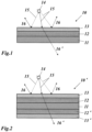
- Fig. 1 shows in a longitudinal cross section the structure and function of a single-sided neutron converter foil according to an example useful for understanding but not forming part of the presently claimed invention.
- the neutron converter foil 10 comprises an optically transparent substrate 11, which is on one side (upper side in Fig. 1 ) covered or coated with an optically transparent neutron converter layer 12 and an optically transparent wavelength shifting layer 13.
- Substrate 11 is in this case a transparent PET foil with a thickness of between 2 ⁇ m and 19 ⁇ m.
- Neutron converter layer 12 contains Li-6 or B-10. Preferably, it contains 95% or higher enriched 6 LiF and a suitable binder in a weight ratio between 1:1 and 15:1. It has a layer thickness of between 1 ⁇ m and 40 ⁇ m, preferably between 3 ⁇ m and 20 ⁇ m.
- the coating of substrate 11 with neutron converter layer 12 is performed in such a way that the coating is highly transparent and adheres well to substrate 11. Furthermore, appropriate measures such as nanosizing LiF crystals or refractive index matching are performed to ensure high transparency.
- Thin wavelength shifting layer 13 is capable of shifting short wavelength light 15 impinging upon it and reemitting (visible) light 16 with a wavelength to which neutron conversion foil 10 is highly transparent (light 16' in Fig. 1 ).
- Wavelength shifting layer 13 contains Tetra Phenyl Butadiene (TPB), an organic wavelength shifter, or an organo silicate compound, and has a layer thickness of between 0.05 ⁇ m and 1 ⁇ m, especially between 0.05 ⁇ m and 0.2 ⁇ m.
- TPB Tetra Phenyl Butadiene
- wavelength shifting layer 13 As said before, if short wavelength light 15, such as light emanating from a neighboring noble gas scintillation incident 14, falls upon wavelength shifting layer 13, it gets shifted to visible light 15.
- the converter membrane is highly transparent to visible light, so that light 16' may cross the foil without notable absorption.
- Neutron converter foil 10 of Fig. 1 is a single-sided foil, i.e. substrate 11 is coated with layers 12 and 13 only on one side.
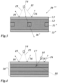
- a double-sided neutron converter foil 10' as per the invention and as shown in Fig. 2 .
- both sides of substrate 11 are coated with neutron conversion layers 12, 12' and wavelength shifting layers 13, 13'.
- neutron converter foil 10' is highly transparent to visible light 16', which for example has been shifted by one of the wavelength shifting layers 13 and 13'. Thicknesses and layer materials of the various layers are the same as for neutron converter foil 10 of Fig. 1 .
- the substrate 11' is a mesh of polystyrene, polyamide, or other suitable material.
- Neutron converter foil 10" in this case has the advantage that more neutron conversion material in mesh-embedding neutron conversion layer 12 is ready to convert a neutron into respective decay products, thereby achieving higher efficiency with thinner coatings while minimizing the energy loss of decay products in the substrate.
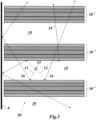
- Fig. 5 shows an embodiment of the neutron detecting device (detector) 20, where several such double-sided membranes or foils 10' are suspended in a scintillation volume 19, which is for example filled with a noble gas.
- the surrounding walls are covered with a highly reflective material A such as a dielectric mirror or diffuse reflector with one or more apertures (not shown in Fig. 5 ), through which photons can impinge on one or more light sensitive devices (B in Fig. 6 ), such as Silicon Photomultipliers (SiPMs) (41 in Fig. 8 ).
- Visible light 16, 16' emanating from the various wavelength shifting layers crosses the foils 10' nearly without attenuation, is reflected reflecting walls (A) and can be collected by light sensitive devices.
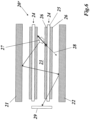
- Fig 6 shows another embodiment of the invention, where in neutron detecting device 20' converter membranes 24 are placed in a scintillation volume 23 between opposite reflectors 21 and 22.
- a transparent LiF coating is applied to both sides of a substrate 25 made of quartz, polyvinyltoluene or other transparent material.
- care must be taken to keep the transparent layers sufficiently thin, such that gamma radiation does not deposit large amounts of energy by scintillation.
- decay products (triton 28) of a captured neutron cause a scintillation incident 27, the light of which reaches light sensitive device 29 after crossing the foils 24 several times.
- Fig. 7 shows a possible low cost signal-processing scheme 30 for an array of several detectors 31 according to this invention.
- the signal-processing unit is composed of a fast multi-channel analogue front-end with 32 channel ASICs units 32 that amplify the signals generated by the SIPMs with detectors 31 and apply a threshold.
- the discriminated signal is fed into a field programmable gate array (FPGA) 33 that measures the pulse width of the signal. Particle to particle and particle to noise discrimination is achieved by applying time coincidence as well as pulse width requirements by means of the FPGA 33.
- the various sub-units are supplied with power by power supply 34.
- a microcontroller 35 is used to read-out the FPGA 33, regulate the power voltage on the power supply 34 and manage the device communication with external interfaces.
- Fig. 8 shows an embodiment of the invention, where in a cascading scheme 36 the number of channels 38, 39 of the signal processing electronics (coincidence unit 37) is kept low by cascading several SiPMs 41 of unit cells 40 for cost reasons.
- Figs. 9 to 14 show a preferred embodiment of a neutron detecting device or detector 42 according to the invention, where a double-sided neutron converter membrane 47 of the kind shown in Figs. 2 to 4 has a total area of about 5 m 2 , arranged in a meandering or accordion style manner in a longitudinal tube 43 (preferably of steel), which is closed by a closure head 44 and contains a scintillation volume 43a filled with noble gas, or the like, through a valve 45 or pinch-off provided on said closure head 44.
- Neutron converter membrane 47 is kept in place by a series of parallel moderating plates 46 oriented perpendicular to the longitudinal tube axis, and being assembled from two separate plate elements 46a and 46b with intertwining fingers (see Fig. 12 ) that subdivide the gas scintillator volume.
- the scintillating noble gas is slightly pressurized and contained by tube 43, which may have a diameter of 10 cm.
- the inside of tube 43 is lined with a highly efficient reflector.
- Printed circuit boards 50 ( Fig. 11 ) with surface mounted SiPMs run down the center of the detector tube 43 and are connected with outside by means of a connecting cable 48.
- FIGs.13 and 14 show a possible assembly method of detector 42 according to Figs. 9 and 10 .
- a foil reel of a (double-sided) converter membrane or foil 47 is used to supply one foil of a width comparable to the length of tube 43.
- the stack of moderating plates 46 is kept in place, whereby the upper plate elements 46a or 46b have been removed to get access to the open finger structure of the remaining plate elements 46b or 46a.
- a sufficient length of foil 47 is unrolled from reel 51 and pushed into the slots 53 of the finger structure by means of a parallel arrangement of guide or pushing rods 52.
- Fig 15 shows, in a top view, a diagonal two-detector arrangement 54 with detectors 42 according to Fig. 9 and 10 in a container 55 with square cross section.
- Fig. 16 shows linear multi-detector arrangement 56 with detectors 42 according to Fig. 9 and 10 in a serial arrangement in a flat rectangular container 57, whereby a common connecting cable 58 is used to connect the internal SiPMs to the external signal processing means (not shown).
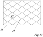
- Fig. 17 shows an embodiment in which the foil or converter membrane 47 can be self suspended by gluing or welding several foils together in defined points such as to form a multidimensional structure that maximizes converter area while keeping foils sufficiently separated to allow neutron capture products to deposit maximal energy in the scintillating gas in scintillation volume 19 without colliding with an obstacle.
- such structure may be achieved by cleverly packing self-supporting geometrical shapes - such as small cylinders and cones - made of converter foil.
- Radioisotope smuggling and black market sales of radioactive material has increased substantially in the past years.
- the neutron detecting device is a valuable tool for being part of a detector network that enables authorities to detect actual locations and moving profiles of such radioactive material.
- Document US 2014/224964 A1 discloses a system including at least one imager having a pixelated chip that is capable of relaying information regarding the interaction of the high energy particle with the pixel while simultaneously obtaining an image, a central command center with a processor for receiving and interpreting said information from the imager, and for issuing operating instructions to remotely control the imager, and means for communication between the imager and the central command center.
- the system may also include at least one processor that is in communication with the imager, which is able to determine that a pixel or pixels have interacted with one or more high energy particle.
- Document US 2009/012745 A1 discloses a radiation detection system including many receivers to continuously receive radiation emission data from at least some of a sufficient density of dispersed detectors capable of communicating geo-positions and photon emission counts over a network; the data includes gamma intensities, time stamps, and geo-positions.
- a processor builds digital image data of the received radiation data for a geographic area by treating gamma-ray proton data from each dispersed detector as a pixel in a low-light image.
- the processor continuously executes a plurality of statistical computational analyses on the digital image data to separate detected radiation signals from random, undesired signal noise, and known signal noise or sources.
- the statistical computational analyses include match-filter and/or other convolution techniques.;
- An interface reports to a user when the computational analyses result in detection of a radiation signal and reports a location of one or more of the dispersed detectors that contribute to the detection.
- Document US 8,502,158 A shows a detection unit for detecting ionizing radiation including a crystal that interacts with incoming radiation; a processing module that analyzes the incoming radiation detected by the crystal; a positioning module that determines position of the detection unit; and a network interface module that receives and transmits time stamped radiation data and position information from/to a plurality of other detection units.
- the detection unit automatically identifies other detection units that are located close to form a cluster.
- the detection unit also includes radiation data integration logic that integrates the incoming radiation data from all detectors in cluster, the position of the detection unit, the received radiation data from other detection units and the received position information from other detection units in real time, and process it simultaneously, that allows significantly improve performance and reliability.
- a neutron detecting device 61 may be part of a (e.g. wide area) detector system 60, wherein a plurality of detector subunits 59 are connected with a control center 68 for evaluating detector data, which have been sent to control center 68 via a wireless network 67.
- a control center 68 for evaluating detector data, which have been sent to control center 68 via a wireless network 67.
- the neutron detecting device 61 may be part of at least one of said detector subunits 59.
- the subunits 59 may be stationary and/or mobile, i.e. mounted in a car or carried by a person.
- neutron detecting device 61 is connected to a computer, especially a single board computer 62.
- Single board computer 62 is connected to a network unit 66, which is able to establish a wireless data transmission between subunit 59 and control center 68 via network 67.
- Single board computer 62 comprises a detector software 63, which is used to monitor detector health and is responsible for neutron counting.
- Single board computer 62 further comprises a data aggregation software/network protocol 64.
- a GPS unit 65 may be provided, which is connected to said single board computer 62.
- the neutron detecting device With the neutron detecting device according to the invention it is possible to evaluate the presence, the intensity and/or the type of gamma radiation interacting with the scintillating volume.
- a certain period of time preferably between 1 and 100 seconds
- overlapping energy spectra of Gamma radiation and neutrons, and the accompanying noise are obtained as shown in Fig. 20 , where 69 denotes the Gamma energy spectrum and 70 denotes the neutron energy spectrum.
- a spectral distribution as shown in Fig. 20 may be done following a scheme according to Fig. 21 .
- the two overlapping spectral distributions 69 and 70 resulting from the simultaneous interaction of Gamma radiation and neutron radiation with the scintillating volume and/or the converter foil are analyzed employing statistical methods.
- the Gamma/neutron count rate ratio 71 is determined and results in a certain value k. Then, k is compared to a predetermined reference value ⁇ (comparisons 72, 73). If k ⁇ , count rates R II (for Gamma radiation) and Rm (for neutrons) are simply added to give the neutron count rate R n (74). If k> ⁇ , a weighted term F(k) x R II is subtracted from the sum R II + R III to give the neutron count rate R n (75). Thus, in this case, the net neutron count rate 75 can be determined by subtracting the spectral response 69 obtained by the gamma radiation from the total spectrum.
Landscapes
- Physics & Mathematics (AREA)
- Spectroscopy & Molecular Physics (AREA)
- Health & Medical Sciences (AREA)
- Life Sciences & Earth Sciences (AREA)
- General Physics & Mathematics (AREA)
- High Energy & Nuclear Physics (AREA)
- Molecular Biology (AREA)
- Measurement Of Radiation (AREA)
- Toxicology (AREA)
- Chemical & Material Sciences (AREA)
- Analytical Chemistry (AREA)
- Biochemistry (AREA)
- General Health & Medical Sciences (AREA)
- Immunology (AREA)
- Pathology (AREA)
Claims (18)
- Dispositif de détection de neutrons (20, 20' ; 42) comprenant un volume de scintillation (19, 23 ; 43a) rempli d'un matériau scintillant tel qu'un gaz noble, une ou plusieurs feuilles de conversion de neutrons (10, 10', 10" ; 47) comprenant un substrat (11, 11') ayant un premier et un second côté, dans lequel ladite ou lesdites une ou plusieurs feuilles de conversion de neutrons (10, 10', 10" ; 47) sont transparentes à la lumière provenant de la conversion des neutrons de sorte que la lumière (16, 16') provenant de la conversion des neutrons peut passer à travers une ou plusieurs desdites feuilles de conversion des neutrons (10, 10', 10" ; 47) et être ensuite recueillie et détectée par un dispositif de détection de lumière (29), dans lequel ledit substrat (11, 1 1') est recouvert sur lesdits premier et second côtés d'une couche de conversion neutronique (12, 12') fabriqué à partir d'un matériau réactif aux neutrons et capable de capturer des neutrons (18) pour ensuite émettre de la lumière et/ou des particules chargées, dans lequel la ou les une ou plusieurs feuilles de conversion de neutrons (10, 10', 10" ; 47) sont prévues dans ledit dispositif de détection de neutrons (20, 20' ; 42) pour être en contact optique avec ledit matériau scintillant de sorte que les produits de conversion chargés (17, 28) résultant de ladite capture de neutrons dans ladite ou lesdites feuilles de conversion de neutrons (10, 10', 10" ; 47) s'échappent dans ledit volume de scintillation (19, 23 ; 43a) et produisent de la lumière, à laquelle ladite ou lesdites feuilles de conversion de neutrons (10, 10', 10" ; 47) est (sont) transparente(s), dans lequel le dispositif de détection de neutrons (20, 20' ; 42) comprend au moins un dispositif de détection de lumière (29) en contact optique avec ledit volume de scintillation (19, 23 ; 43a), caractérisé en ce que ledit au moins un dispositif de détection de lumière (29) est un capteur de lumière solide, en particulier un photomultiplicateur au silicium (SiPM) ou une photodiode à avalanche en mode Geiger pixel-lisée.
- Dispositif de détection de neutrons selon la revendication 1, caractérisé en ce que le volume de scintillation (19, 23 ; 43a) est composé principalement d'un gaz noble tel que l'hélium, l'argon ou le xénon ou d'un mélange de gaz nobles, tel que l'hélium dopé au xénon.
- Dispositif de détection de neutrons selon la revendication 2, caractérisé en ce que ledit volume de scintillation (19, 23 ; 43a) est principalement rempli d'hélium, ce qui permet de mesurer et de distinguer simultanément les neutrons rapides, les neutrons thermiques et/ou les photons et les électrons produits par l'interaction des photons avec une paroi du détecteur, ou en ce que ledit volume de scintillation (19, 23 ; 43a) est principalement rempli de xénon, ce qui permet d'effectuer une spectrométrie gamma tout en mesurant les neutrons.
- Dispositif de détection de neutrons selon la revendication 1, caractérisé en ce que le volume de scintillation (19, 23 ; 43a) contient principalement du PVT ou un scintillateur liquide, ce qui permet la mesure simultanée des gammas et des neutrons.
- Dispositif de détection de neutrons selon la revendication 1, caractérisé en ce que ledit au moins un capteur de lumière solide (29) est disposé à l'intérieur dudit volume de scintillation (19, 23 ; 43a).
- Dispositif de détection de neutrons selon la revendication 2, caractérisé en ce qu'un dispositif de purification de gaz in situ, tel qu'un getter, est immergé dans le gaz dudit volume de scintillation (19, 23 ; 43a), assurant ainsi une composition de gaz stable.
- Dispositif de détection de neutrons selon la revendication 1, caractérisé en ce que le volume de scintillation (19, 23 ; 43a) est entouré d'un matériau hautement réfléchissant (A, 21, 22) dans la zone duquel plusieurs dispositifs de détection de lumière (29) peuvent être intercalés.
- Dispositif de détection de neutrons selon la revendication 1, caractérisé en ce que plusieurs feuilles de conversion de neutrons (10, 10', 10" ; 47) sont disposées en parallèle dans ledit volume de scintillation (19, 23 ; 43a).
- Dispositif de détection de neutrons selon la revendication 1, caractérisé en ce que ledit dispositif de détection de neutrons (61) fait partie d'un système de détection (60), dans lequel plusieurs sous-unités de détection (59) sont connectées à un centre de contrôle (68) pour évaluer les données des détecteurs via un réseau sans fil (67), ledit dispositif de détection de neutrons (61) faisant de préférence partie d'au moins une de ces sous-unités de détection (59).
- Dispositif de détection de neutrons selon la revendication 9, caractérisé en ce que ledit dispositif de détection de neutrons (61) est connecté dans ladite sous-unité de détection (59) à un ordinateur monocarte (62), qui est lui-même connecté à une unité de réseau (66) et comprend un logiciel de détection (63) et un logiciel d'agrégation de données/protocole de réseau (64).
- Dispositif de détection de neutrons selon la revendication 9, caractérisé en ce qu'une unité GPS (65) pour déterminer la position actuelle de ladite sous-unité de détection (59) est connectée à l'ordinateur monocarte (62).
- Dispositif de détection de neutrons selon la revendication 1, caractérisé en ce que la couche de conversion neutronique (12, 12') contient du Li-6 ou du B-10.
- Dispositif de détection de neutrons selon la revendication 12, caractérisé en ce que ladite couche de conversion neutronique (12, 12') contient du LiF et un liant dans un rapport pondéral compris entre 1:1 et 15:1, et que des mesures telles que la nanostructuration du LiF ou l'adaptation de l'indice de réfraction sont effectuées.
- Dispositif de détection de neutrons selon la revendication 12, caractérisé en ce que ladite couche de conversion neutronique (12, 12') a une épaisseur comprise entre 1 µm et 40 µm, en particulier entre 3 µm et 20 µm.
- Dispositif de détection de neutrons selon la revendication 1, caractérisé en ce que ledit substrat (11) est une feuille de PET transparente, ladite feuille de PET transparente ayant de préférence une épaisseur comprise entre 2 µm et 19 µm.
- Dispositif de détection de neutrons selon la revendication 1, caractérisé en ce que ladite couche de conversion neutronique (12, 12') est recouverte d'une couche de décalage de longueur d'onde (13, 13') capable de décaler la lumière de courte longueur d'onde (15) qui lui parvient et de réé-mettre une lumière d'une longueur d'onde à laquelle ladite feuille de conversion de neutrons (10, 10', 10" ; 47) est transparente.
- Dispositif de détection de neutrons selon la revendication 16, caractérisé en ce que ladite couche de décalage de longueur d'onde (13, 13') contient du Tétra Phényl Butadiène (TPB), un décalage de longueur d'onde organique, ou un composé organo-silicaté, ladite couche de décalage de longueur d'onde (13, 13') ayant de préférence une épaisseur de couche comprise entre 0,05 µm et 1 µm, en particulier entre 0,05 µm et 0,2 µm.
- Dispositif de détection de neutrons selon la revendication 1, caractérisé en ce que le substrat (1 1 ') est un treillis.
Applications Claiming Priority (2)
| Application Number | Priority Date | Filing Date | Title |
|---|---|---|---|
| CH20242014 | 2014-12-22 | ||
| PCT/EP2015/080822 WO2016102484A1 (fr) | 2014-12-22 | 2015-12-21 | Feuille de conversion de neutrons, dispositif de détection de neutrons ayant une telle feuille, et procédé de fonctionnement d'un tel dispositif de détection de neutrons |
Publications (3)
| Publication Number | Publication Date |
|---|---|
| EP3237933A1 EP3237933A1 (fr) | 2017-11-01 |
| EP3237933C0 EP3237933C0 (fr) | 2024-08-28 |
| EP3237933B1 true EP3237933B1 (fr) | 2024-08-28 |
Family
ID=53476615
Family Applications (1)
| Application Number | Title | Priority Date | Filing Date |
|---|---|---|---|
| EP15816471.5A Active EP3237933B1 (fr) | 2014-12-22 | 2015-12-21 | Dispositif de detection de neutrons comprenant une feuille de conversion de neutron |
Country Status (4)
| Country | Link |
|---|---|
| US (1) | US10274619B2 (fr) |
| EP (1) | EP3237933B1 (fr) |
| HK (1) | HK1246399A1 (fr) |
| WO (1) | WO2016102484A1 (fr) |
Families Citing this family (5)
| Publication number | Priority date | Publication date | Assignee | Title |
|---|---|---|---|---|
| US10996353B1 (en) * | 2017-10-10 | 2021-05-04 | The United States Of America, As Represented By The Secretary Of The Navy | N-type gallium nitride scintillation for fast-neutron detection |
| US11175417B1 (en) * | 2019-09-30 | 2021-11-16 | National Technology & Engineering Solutions Of Sandia, Llc | Mutli-layered neutron detector |
| CN113063808B (zh) * | 2021-03-29 | 2024-09-03 | 卡尔蔡司工业测量技术有限公司 | 用于检验至少一个测试物体的检验系统和方法 |
| WO2024068397A1 (fr) * | 2022-09-27 | 2024-04-04 | Thermo Fisher Scientific Messtechnik Gmbh | Détecteur de rayonnement et procédé de formation d'un détecteur de rayonnement |
| CN119916430B (zh) * | 2025-02-25 | 2025-10-21 | 南华大学 | 双cmos传感器与转换材料组合的中子测量系统 |
Citations (17)
| Publication number | Priority date | Publication date | Assignee | Title |
|---|---|---|---|---|
| US3891852A (en) * | 1972-11-03 | 1975-06-24 | Agfa Gevaert Nv | Neutron detection and radiography |
| US5672465A (en) * | 1990-04-09 | 1997-09-30 | Jp Laboratories, Inc. | Polyethyleneimine binder complex films |
| US20070102647A1 (en) * | 2005-11-04 | 2007-05-10 | The University Of Chicago | Multi-radiation large area detector |
| WO2007121876A2 (fr) * | 2006-04-18 | 2007-11-01 | ETH Zürich | Procédé d'examen d'un récipient inconnu ou du contenu de volumes, et système et détecteurs de rayonnement associés |
| US20090078851A1 (en) * | 2005-07-01 | 2009-03-26 | National Institute For Materials Science | Far Ultraviolet With High Luminance Emitting High-Purity Hexagonal Boron Nitride Monocrystalline Powder And Method Of Manufacturing The Same |
| US20090166549A1 (en) * | 2008-01-02 | 2009-07-02 | Czirr J Bart | Heterogeneous capture-gated neutron spectrometer |
| WO2010087844A1 (fr) * | 2009-01-30 | 2010-08-05 | Alliance For Sustainable Energy, Llc | Détecteur de neutrons « état solide » à haute sensibilité |
| US20100276602A1 (en) * | 2008-02-07 | 2010-11-04 | General Electric Company | Radiation detector with optical waveguide and neutron scintillating material |
| US20100294943A1 (en) * | 2005-12-01 | 2010-11-25 | Innovative American Technology Inc. | High performance neutron detector with near zero gamma cross talk |
| WO2010144227A2 (fr) * | 2009-06-12 | 2010-12-16 | Saint-Gobain Ceramics & Plastics, Inc. | Détecteur à scintillateur à grand rapport d'aspect, pour la détection de neutrons |
| GB2474720A (en) * | 2009-10-26 | 2011-04-27 | Finphys Oy | Neutron Detector |
| US20120292519A1 (en) * | 2011-05-17 | 2012-11-22 | Saint-Gobain Ceramics & Plastics, Inc. | Optical fiber having a coating, a radiation sensor and a radiation detection apparatus including the optical fiber and a method of making using the same |
| US20130034198A1 (en) * | 2011-08-02 | 2013-02-07 | Chandrasekharan Rico S | Noble gas detector for fissile content determination |
| GB2499391A (en) * | 2012-02-14 | 2013-08-21 | Symetrica Ltd | Neutron detector |
| EP2770342A1 (fr) * | 2013-02-25 | 2014-08-27 | Symetrica Limited | Détecteur de neutrons et procédé permettant de détecter des neutrons |
| WO2015131124A1 (fr) * | 2014-02-27 | 2015-09-03 | Saint-Gobain Ceramics & Plastics, Inc. | Empilement de scintillateur, dispositif comportant l'empilement de scintillateur et procédé de fabrication de l'empilement de scintillateur |
| WO2015173540A1 (fr) * | 2014-05-14 | 2015-11-19 | Symetrica Limited | Détection de neutrons |
Family Cites Families (11)
| Publication number | Priority date | Publication date | Assignee | Title |
|---|---|---|---|---|
| JPH08338876A (ja) * | 1995-06-13 | 1996-12-24 | Mitsubishi Electric Corp | 粒子計量器、粒子計量方法および原子力プラント |
| US6373066B1 (en) | 1999-08-20 | 2002-04-16 | Saint-Gobain Industrial Ceramics, Inc. | Thermal neutron detector using a scintillator with background gamma ray shielding |
| WO2004043372A2 (fr) | 2002-11-13 | 2004-05-27 | Proportional Technologies, Inc. | Detecteur de neutrons par tubes pailles enduits de bore |
| US6867444B1 (en) * | 2003-10-20 | 2005-03-15 | The United States Of America As Represented By The Secretary Of The Navy | Semiconductor substrate incorporating a neutron conversion layer |
| US20090302226A1 (en) * | 2005-02-08 | 2009-12-10 | Yissum Research Development Company Of The Hebrew University Of Jerusalem | Solid-state neutron and alpha particles detector and methods for manufacturing and use thereof |
| US7994926B2 (en) | 2007-07-05 | 2011-08-09 | Purdue Research Foundation | Nuclear detection via a system of widely distributed low cost detectors having data including gamma intensities, time stamps and geo-positions |
| WO2011025853A1 (fr) | 2009-08-27 | 2011-03-03 | Mcgregor Douglas S | Détecteurs de neutrons à gaz dont lefficacité de détection est améliorée |
| US9817138B2 (en) | 2009-08-27 | 2017-11-14 | Douglas S. McGregor | Gas-filled neutron detectors and imaging system and array of such detectors |
| US8502158B1 (en) | 2010-04-07 | 2013-08-06 | Polimaster IP Solutions LLC | Distributed system for radiation detection utilizing multiple clustered detectors |
| GB2482024A (en) * | 2010-07-16 | 2012-01-18 | Symetrica Ltd | Radiation Detector |
| WO2014124359A1 (fr) | 2013-02-08 | 2014-08-14 | Image Insight Inc. | Appareil et procédé de détection de rayonnement |
-
2015
- 2015-12-21 EP EP15816471.5A patent/EP3237933B1/fr active Active
- 2015-12-21 US US15/538,389 patent/US10274619B2/en active Active
- 2015-12-21 HK HK18105604.7A patent/HK1246399A1/zh unknown
- 2015-12-21 WO PCT/EP2015/080822 patent/WO2016102484A1/fr not_active Ceased
Patent Citations (17)
| Publication number | Priority date | Publication date | Assignee | Title |
|---|---|---|---|---|
| US3891852A (en) * | 1972-11-03 | 1975-06-24 | Agfa Gevaert Nv | Neutron detection and radiography |
| US5672465A (en) * | 1990-04-09 | 1997-09-30 | Jp Laboratories, Inc. | Polyethyleneimine binder complex films |
| US20090078851A1 (en) * | 2005-07-01 | 2009-03-26 | National Institute For Materials Science | Far Ultraviolet With High Luminance Emitting High-Purity Hexagonal Boron Nitride Monocrystalline Powder And Method Of Manufacturing The Same |
| US20070102647A1 (en) * | 2005-11-04 | 2007-05-10 | The University Of Chicago | Multi-radiation large area detector |
| US20100294943A1 (en) * | 2005-12-01 | 2010-11-25 | Innovative American Technology Inc. | High performance neutron detector with near zero gamma cross talk |
| WO2007121876A2 (fr) * | 2006-04-18 | 2007-11-01 | ETH Zürich | Procédé d'examen d'un récipient inconnu ou du contenu de volumes, et système et détecteurs de rayonnement associés |
| US20090166549A1 (en) * | 2008-01-02 | 2009-07-02 | Czirr J Bart | Heterogeneous capture-gated neutron spectrometer |
| US20100276602A1 (en) * | 2008-02-07 | 2010-11-04 | General Electric Company | Radiation detector with optical waveguide and neutron scintillating material |
| WO2010087844A1 (fr) * | 2009-01-30 | 2010-08-05 | Alliance For Sustainable Energy, Llc | Détecteur de neutrons « état solide » à haute sensibilité |
| WO2010144227A2 (fr) * | 2009-06-12 | 2010-12-16 | Saint-Gobain Ceramics & Plastics, Inc. | Détecteur à scintillateur à grand rapport d'aspect, pour la détection de neutrons |
| GB2474720A (en) * | 2009-10-26 | 2011-04-27 | Finphys Oy | Neutron Detector |
| US20120292519A1 (en) * | 2011-05-17 | 2012-11-22 | Saint-Gobain Ceramics & Plastics, Inc. | Optical fiber having a coating, a radiation sensor and a radiation detection apparatus including the optical fiber and a method of making using the same |
| US20130034198A1 (en) * | 2011-08-02 | 2013-02-07 | Chandrasekharan Rico S | Noble gas detector for fissile content determination |
| GB2499391A (en) * | 2012-02-14 | 2013-08-21 | Symetrica Ltd | Neutron detector |
| EP2770342A1 (fr) * | 2013-02-25 | 2014-08-27 | Symetrica Limited | Détecteur de neutrons et procédé permettant de détecter des neutrons |
| WO2015131124A1 (fr) * | 2014-02-27 | 2015-09-03 | Saint-Gobain Ceramics & Plastics, Inc. | Empilement de scintillateur, dispositif comportant l'empilement de scintillateur et procédé de fabrication de l'empilement de scintillateur |
| WO2015173540A1 (fr) * | 2014-05-14 | 2015-11-19 | Symetrica Limited | Détection de neutrons |
Also Published As
| Publication number | Publication date |
|---|---|
| WO2016102484A1 (fr) | 2016-06-30 |
| EP3237933C0 (fr) | 2024-08-28 |
| US20180024256A1 (en) | 2018-01-25 |
| EP3237933A1 (fr) | 2017-11-01 |
| HK1246399A1 (zh) | 2018-09-07 |
| US10274619B2 (en) | 2019-04-30 |
Similar Documents
| Publication | Publication Date | Title |
|---|---|---|
| RU2411543C2 (ru) | Детектор гамма- и нейтронного излучения | |
| US6924487B2 (en) | Neutron detector | |
| US7582880B2 (en) | Neutron detector using lithiated glass-scintillating particle composite | |
| US8710449B2 (en) | Plasma panel based radiation detector | |
| US7741612B2 (en) | Integrated neutron-gamma radiation detector with optical waveguide and neutron scintillating material | |
| US10274619B2 (en) | Neutron conversion foil, neutron detecting device with such a foil, and method for operating such a neutron-detecting device | |
| US8101919B2 (en) | Isotopic response with small scintillator based gamma-ray spectrometers | |
| US20100276602A1 (en) | Radiation detector with optical waveguide and neutron scintillating material | |
| US9651689B2 (en) | Detector arrangement for the detection of ionizing radiation and method for operating such a detector arrangement | |
| Stowell et al. | Scintillating thermal neutron detectors for cosmic ray soil moisture monitoring | |
| EP3441793B1 (fr) | Réseau de scintillateurs | |
| RU2297015C1 (ru) | Сцинтилляционный детектор | |
| RU2142147C1 (ru) | Сцинтилляционный детектор | |
| JP2001013254A (ja) | 平板状中性子線検出器及びこれを用いた中性子源計測装置 | |
| RU105474U1 (ru) | Детектор для регистрации ионизирующих излучений | |
| RU2814061C1 (ru) | Сцинтилляционный детектор нейтронного и гамма-излучения | |
| CN110988964A (zh) | 复合型光纤辐射探测器 | |
| RU54438U1 (ru) | Преобразователь ионизирующего излучения | |
| Barbagallo et al. | Development of a thermal neutron detector based on scintillating fibers and silicon photomultipliers | |
| RU100297U1 (ru) | Двухкоординатный детектор | |
| Vanier et al. | Applications of Noble Gas Radiation Detectors to Counter‐terrorism | |
| Atkins et al. | Instrumented water tanks can improve air shower detector sensitivity |
Legal Events
| Date | Code | Title | Description |
|---|---|---|---|
| STAA | Information on the status of an ep patent application or granted ep patent |
Free format text: STATUS: THE INTERNATIONAL PUBLICATION HAS BEEN MADE |
|
| PUAI | Public reference made under article 153(3) epc to a published international application that has entered the european phase |
Free format text: ORIGINAL CODE: 0009012 |
|
| STAA | Information on the status of an ep patent application or granted ep patent |
Free format text: STATUS: REQUEST FOR EXAMINATION WAS MADE |
|
| 17P | Request for examination filed |
Effective date: 20170721 |
|
| AK | Designated contracting states |
Kind code of ref document: A1 Designated state(s): AL AT BE BG CH CY CZ DE DK EE ES FI FR GB GR HR HU IE IS IT LI LT LU LV MC MK MT NL NO PL PT RO RS SE SI SK SM TR |
|
| AX | Request for extension of the european patent |
Extension state: BA ME |
|
| RIN1 | Information on inventor provided before grant (corrected) |
Inventor name: CHANDRASEKHARAN, RICO Inventor name: GENDOTTI, ULISSE |
|
| DAV | Request for validation of the european patent (deleted) | ||
| DAX | Request for extension of the european patent (deleted) | ||
| REG | Reference to a national code |
Ref country code: HK Ref legal event code: DE Ref document number: 1246399 Country of ref document: HK |
|
| STAA | Information on the status of an ep patent application or granted ep patent |
Free format text: STATUS: EXAMINATION IS IN PROGRESS |
|
| 17Q | First examination report despatched |
Effective date: 20190614 |
|
| GRAP | Despatch of communication of intention to grant a patent |
Free format text: ORIGINAL CODE: EPIDOSNIGR1 |
|
| STAA | Information on the status of an ep patent application or granted ep patent |
Free format text: STATUS: GRANT OF PATENT IS INTENDED |
|
| INTG | Intention to grant announced |
Effective date: 20230623 |
|
| RIN1 | Information on inventor provided before grant (corrected) |
Inventor name: CHANDRASEKHARAN, RICO Inventor name: GENDOTTI, ULISSE |
|
| GRAJ | Information related to disapproval of communication of intention to grant by the applicant or resumption of examination proceedings by the epo deleted |
Free format text: ORIGINAL CODE: EPIDOSDIGR1 |
|
| STAA | Information on the status of an ep patent application or granted ep patent |
Free format text: STATUS: EXAMINATION IS IN PROGRESS |
|
| GRAP | Despatch of communication of intention to grant a patent |
Free format text: ORIGINAL CODE: EPIDOSNIGR1 |
|
| STAA | Information on the status of an ep patent application or granted ep patent |
Free format text: STATUS: GRANT OF PATENT IS INTENDED |
|
| INTC | Intention to grant announced (deleted) | ||
| INTG | Intention to grant announced |
Effective date: 20231113 |
|
| GRAJ | Information related to disapproval of communication of intention to grant by the applicant or resumption of examination proceedings by the epo deleted |
Free format text: ORIGINAL CODE: EPIDOSDIGR1 |
|
| STAA | Information on the status of an ep patent application or granted ep patent |
Free format text: STATUS: EXAMINATION IS IN PROGRESS |
|
| GRAP | Despatch of communication of intention to grant a patent |
Free format text: ORIGINAL CODE: EPIDOSNIGR1 |
|
| STAA | Information on the status of an ep patent application or granted ep patent |
Free format text: STATUS: GRANT OF PATENT IS INTENDED |
|
| INTC | Intention to grant announced (deleted) | ||
| INTG | Intention to grant announced |
Effective date: 20240322 |
|
| REG | Reference to a national code |
Ref country code: HK Ref legal event code: WD Ref document number: 1246399 Country of ref document: HK |
|
| GRAS | Grant fee paid |
Free format text: ORIGINAL CODE: EPIDOSNIGR3 |
|
| GRAA | (expected) grant |
Free format text: ORIGINAL CODE: 0009210 |
|
| STAA | Information on the status of an ep patent application or granted ep patent |
Free format text: STATUS: THE PATENT HAS BEEN GRANTED |
|
| AK | Designated contracting states |
Kind code of ref document: B1 Designated state(s): AL AT BE BG CH CY CZ DE DK EE ES FI FR GB GR HR HU IE IS IT LI LT LU LV MC MK MT NL NO PL PT RO RS SE SI SK SM TR |
|
| REG | Reference to a national code |
Ref country code: GB Ref legal event code: FG4D |
|
| REG | Reference to a national code |
Ref country code: CH Ref legal event code: EP |
|
| REG | Reference to a national code |
Ref country code: DE Ref legal event code: R096 Ref document number: 602015089701 Country of ref document: DE |
|
| REG | Reference to a national code |
Ref country code: IE Ref legal event code: FG4D |
|
| U01 | Request for unitary effect filed |
Effective date: 20240927 |
|
| U07 | Unitary effect registered |
Designated state(s): AT BE BG DE DK EE FI FR IT LT LU LV MT NL PT RO SE SI Effective date: 20241106 |
|
| PG25 | Lapsed in a contracting state [announced via postgrant information from national office to epo] |
Ref country code: NO Free format text: LAPSE BECAUSE OF FAILURE TO SUBMIT A TRANSLATION OF THE DESCRIPTION OR TO PAY THE FEE WITHIN THE PRESCRIBED TIME-LIMIT Effective date: 20241128 |
|
| U20 | Renewal fee for the european patent with unitary effect paid |
Year of fee payment: 10 Effective date: 20241210 |
|
| PG25 | Lapsed in a contracting state [announced via postgrant information from national office to epo] |
Ref country code: GR Free format text: LAPSE BECAUSE OF FAILURE TO SUBMIT A TRANSLATION OF THE DESCRIPTION OR TO PAY THE FEE WITHIN THE PRESCRIBED TIME-LIMIT Effective date: 20241129 Ref country code: PL Free format text: LAPSE BECAUSE OF FAILURE TO SUBMIT A TRANSLATION OF THE DESCRIPTION OR TO PAY THE FEE WITHIN THE PRESCRIBED TIME-LIMIT Effective date: 20240828 |
|
| PG25 | Lapsed in a contracting state [announced via postgrant information from national office to epo] |
Ref country code: IS Free format text: LAPSE BECAUSE OF FAILURE TO SUBMIT A TRANSLATION OF THE DESCRIPTION OR TO PAY THE FEE WITHIN THE PRESCRIBED TIME-LIMIT Effective date: 20241228 |
|
| PG25 | Lapsed in a contracting state [announced via postgrant information from national office to epo] |
Ref country code: HR Free format text: LAPSE BECAUSE OF FAILURE TO SUBMIT A TRANSLATION OF THE DESCRIPTION OR TO PAY THE FEE WITHIN THE PRESCRIBED TIME-LIMIT Effective date: 20240828 |
|
| PG25 | Lapsed in a contracting state [announced via postgrant information from national office to epo] |
Ref country code: RS Free format text: LAPSE BECAUSE OF FAILURE TO SUBMIT A TRANSLATION OF THE DESCRIPTION OR TO PAY THE FEE WITHIN THE PRESCRIBED TIME-LIMIT Effective date: 20241128 Ref country code: ES Free format text: LAPSE BECAUSE OF FAILURE TO SUBMIT A TRANSLATION OF THE DESCRIPTION OR TO PAY THE FEE WITHIN THE PRESCRIBED TIME-LIMIT Effective date: 20240828 |
|
| PG25 | Lapsed in a contracting state [announced via postgrant information from national office to epo] |
Ref country code: RS Free format text: LAPSE BECAUSE OF FAILURE TO SUBMIT A TRANSLATION OF THE DESCRIPTION OR TO PAY THE FEE WITHIN THE PRESCRIBED TIME-LIMIT Effective date: 20241128 Ref country code: PL Free format text: LAPSE BECAUSE OF FAILURE TO SUBMIT A TRANSLATION OF THE DESCRIPTION OR TO PAY THE FEE WITHIN THE PRESCRIBED TIME-LIMIT Effective date: 20240828 Ref country code: NO Free format text: LAPSE BECAUSE OF FAILURE TO SUBMIT A TRANSLATION OF THE DESCRIPTION OR TO PAY THE FEE WITHIN THE PRESCRIBED TIME-LIMIT Effective date: 20241128 Ref country code: IS Free format text: LAPSE BECAUSE OF FAILURE TO SUBMIT A TRANSLATION OF THE DESCRIPTION OR TO PAY THE FEE WITHIN THE PRESCRIBED TIME-LIMIT Effective date: 20241228 Ref country code: HR Free format text: LAPSE BECAUSE OF FAILURE TO SUBMIT A TRANSLATION OF THE DESCRIPTION OR TO PAY THE FEE WITHIN THE PRESCRIBED TIME-LIMIT Effective date: 20240828 Ref country code: GR Free format text: LAPSE BECAUSE OF FAILURE TO SUBMIT A TRANSLATION OF THE DESCRIPTION OR TO PAY THE FEE WITHIN THE PRESCRIBED TIME-LIMIT Effective date: 20241129 Ref country code: ES Free format text: LAPSE BECAUSE OF FAILURE TO SUBMIT A TRANSLATION OF THE DESCRIPTION OR TO PAY THE FEE WITHIN THE PRESCRIBED TIME-LIMIT Effective date: 20240828 |
|
| PG25 | Lapsed in a contracting state [announced via postgrant information from national office to epo] |
Ref country code: SM Free format text: LAPSE BECAUSE OF FAILURE TO SUBMIT A TRANSLATION OF THE DESCRIPTION OR TO PAY THE FEE WITHIN THE PRESCRIBED TIME-LIMIT Effective date: 20240828 |
|
| PG25 | Lapsed in a contracting state [announced via postgrant information from national office to epo] |
Ref country code: CZ Free format text: LAPSE BECAUSE OF FAILURE TO SUBMIT A TRANSLATION OF THE DESCRIPTION OR TO PAY THE FEE WITHIN THE PRESCRIBED TIME-LIMIT Effective date: 20240828 |
|
| PG25 | Lapsed in a contracting state [announced via postgrant information from national office to epo] |
Ref country code: SK Free format text: LAPSE BECAUSE OF FAILURE TO SUBMIT A TRANSLATION OF THE DESCRIPTION OR TO PAY THE FEE WITHIN THE PRESCRIBED TIME-LIMIT Effective date: 20240828 |
|
| PLBE | No opposition filed within time limit |
Free format text: ORIGINAL CODE: 0009261 |
|
| STAA | Information on the status of an ep patent application or granted ep patent |
Free format text: STATUS: NO OPPOSITION FILED WITHIN TIME LIMIT |
|
| PG25 | Lapsed in a contracting state [announced via postgrant information from national office to epo] |
Ref country code: MC Free format text: LAPSE BECAUSE OF FAILURE TO SUBMIT A TRANSLATION OF THE DESCRIPTION OR TO PAY THE FEE WITHIN THE PRESCRIBED TIME-LIMIT Effective date: 20240828 |
|
| 26N | No opposition filed |
Effective date: 20250530 |
|
| PG25 | Lapsed in a contracting state [announced via postgrant information from national office to epo] |
Ref country code: IE Free format text: LAPSE BECAUSE OF NON-PAYMENT OF DUE FEES Effective date: 20241221 |
|
| REG | Reference to a national code |
Ref country code: CH Ref legal event code: U11 Free format text: ST27 STATUS EVENT CODE: U-0-0-U10-U11 (AS PROVIDED BY THE NATIONAL OFFICE) Effective date: 20260101 |
|
| PGFP | Annual fee paid to national office [announced via postgrant information from national office to epo] |
Ref country code: GB Payment date: 20251219 Year of fee payment: 11 |
|
| U20 | Renewal fee for the european patent with unitary effect paid |
Year of fee payment: 11 Effective date: 20251210 |
|
| PGFP | Annual fee paid to national office [announced via postgrant information from national office to epo] |
Ref country code: CH Payment date: 20260101 Year of fee payment: 11 |