EP3238440B1 - Afficheurs électroniques à grande échelle - Google Patents
Afficheurs électroniques à grande échelle Download PDFInfo
- Publication number
- EP3238440B1 EP3238440B1 EP15828838.1A EP15828838A EP3238440B1 EP 3238440 B1 EP3238440 B1 EP 3238440B1 EP 15828838 A EP15828838 A EP 15828838A EP 3238440 B1 EP3238440 B1 EP 3238440B1
- Authority
- EP
- European Patent Office
- Prior art keywords
- door
- display
- scale electronic
- sub
- electronic display
- Prior art date
- Legal status (The legal status is an assumption and is not a legal conclusion. Google has not performed a legal analysis and makes no representation as to the accuracy of the status listed.)
- Active
Links
Images


















Classifications
-
- H—ELECTRICITY
- H04—ELECTRIC COMMUNICATION TECHNIQUE
- H04N—PICTORIAL COMMUNICATION, e.g. TELEVISION
- H04N5/00—Details of television systems
- H04N5/64—Constructional details of receivers, e.g. cabinets or dust covers
-
- B—PERFORMING OPERATIONS; TRANSPORTING
- B65—CONVEYING; PACKING; STORING; HANDLING THIN OR FILAMENTARY MATERIAL
- B65G—TRANSPORT OR STORAGE DEVICES, e.g. CONVEYORS FOR LOADING OR TIPPING, SHOP CONVEYOR SYSTEMS OR PNEUMATIC TUBE CONVEYORS
- B65G49/00—Conveying systems characterised by their application for specified purposes not otherwise provided for
-
- B—PERFORMING OPERATIONS; TRANSPORTING
- B65—CONVEYING; PACKING; STORING; HANDLING THIN OR FILAMENTARY MATERIAL
- B65G—TRANSPORT OR STORAGE DEVICES, e.g. CONVEYORS FOR LOADING OR TIPPING, SHOP CONVEYOR SYSTEMS OR PNEUMATIC TUBE CONVEYORS
- B65G7/00—Devices for assisting manual moving or tilting heavy loads
- B65G7/02—Devices adapted to be interposed between loads and the ground or floor, e.g. crowbars with means for assisting conveyance of loads
- B65G7/04—Rollers
-
- B—PERFORMING OPERATIONS; TRANSPORTING
- B66—HOISTING; LIFTING; HAULING
- B66C—CRANES; LOAD-ENGAGING ELEMENTS OR DEVICES FOR CRANES, CAPSTANS, WINCHES, OR TACKLES
- B66C1/00—Load-engaging elements or devices attached to lifting or lowering gear of cranes or adapted for connection therewith for transmitting lifting forces to articles or groups of articles
- B66C1/10—Load-engaging elements or devices attached to lifting or lowering gear of cranes or adapted for connection therewith for transmitting lifting forces to articles or groups of articles by mechanical means
- B66C1/62—Load-engaging elements or devices attached to lifting or lowering gear of cranes or adapted for connection therewith for transmitting lifting forces to articles or groups of articles by mechanical means comprising article-engaging members of a shape complementary to that of the articles to be handled
- B66C1/66—Load-engaging elements or devices attached to lifting or lowering gear of cranes or adapted for connection therewith for transmitting lifting forces to articles or groups of articles by mechanical means comprising article-engaging members of a shape complementary to that of the articles to be handled for engaging holes, recesses, or abutments on articles specially provided for facilitating handling thereof
-
- F—MECHANICAL ENGINEERING; LIGHTING; HEATING; WEAPONS; BLASTING
- F16—ENGINEERING ELEMENTS AND UNITS; GENERAL MEASURES FOR PRODUCING AND MAINTAINING EFFECTIVE FUNCTIONING OF MACHINES OR INSTALLATIONS; THERMAL INSULATION IN GENERAL
- F16M—FRAMES, CASINGS OR BEDS OF ENGINES, MACHINES OR APPARATUS, NOT SPECIFIC TO ENGINES, MACHINES OR APPARATUS PROVIDED FOR ELSEWHERE; STANDS; SUPPORTS
- F16M11/00—Stands or trestles as supports for apparatus or articles placed thereon ; Stands for scientific apparatus such as gravitational force meters
- F16M11/20—Undercarriages with or without wheels
- F16M11/24—Undercarriages with or without wheels changeable in height or length of legs, also for transport only, e.g. by means of tubes screwed into each other
-
- G—PHYSICS
- G02—OPTICS
- G02F—OPTICAL DEVICES OR ARRANGEMENTS FOR THE CONTROL OF LIGHT BY MODIFICATION OF THE OPTICAL PROPERTIES OF THE MEDIA OF THE ELEMENTS INVOLVED THEREIN; NON-LINEAR OPTICS; FREQUENCY-CHANGING OF LIGHT; OPTICAL LOGIC ELEMENTS; OPTICAL ANALOGUE/DIGITAL CONVERTERS
- G02F1/00—Devices or arrangements for the control of the intensity, colour, phase, polarisation or direction of light arriving from an independent light source, e.g. switching, gating or modulating; Non-linear optics
- G02F1/01—Devices or arrangements for the control of the intensity, colour, phase, polarisation or direction of light arriving from an independent light source, e.g. switching, gating or modulating; Non-linear optics for the control of the intensity, phase, polarisation or colour
- G02F1/13—Devices or arrangements for the control of the intensity, colour, phase, polarisation or direction of light arriving from an independent light source, e.g. switching, gating or modulating; Non-linear optics for the control of the intensity, phase, polarisation or colour based on liquid crystals, e.g. single liquid crystal display cells
- G02F1/133—Constructional arrangements; Operation of liquid crystal cells; Circuit arrangements
- G02F1/1333—Constructional arrangements; Manufacturing methods
-
- G—PHYSICS
- G02—OPTICS
- G02F—OPTICAL DEVICES OR ARRANGEMENTS FOR THE CONTROL OF LIGHT BY MODIFICATION OF THE OPTICAL PROPERTIES OF THE MEDIA OF THE ELEMENTS INVOLVED THEREIN; NON-LINEAR OPTICS; FREQUENCY-CHANGING OF LIGHT; OPTICAL LOGIC ELEMENTS; OPTICAL ANALOGUE/DIGITAL CONVERTERS
- G02F1/00—Devices or arrangements for the control of the intensity, colour, phase, polarisation or direction of light arriving from an independent light source, e.g. switching, gating or modulating; Non-linear optics
- G02F1/01—Devices or arrangements for the control of the intensity, colour, phase, polarisation or direction of light arriving from an independent light source, e.g. switching, gating or modulating; Non-linear optics for the control of the intensity, phase, polarisation or colour
- G02F1/13—Devices or arrangements for the control of the intensity, colour, phase, polarisation or direction of light arriving from an independent light source, e.g. switching, gating or modulating; Non-linear optics for the control of the intensity, phase, polarisation or colour based on liquid crystals, e.g. single liquid crystal display cells
- G02F1/133—Constructional arrangements; Operation of liquid crystal cells; Circuit arrangements
- G02F1/1333—Constructional arrangements; Manufacturing methods
- G02F1/133382—Heating or cooling of liquid crystal cells other than for activation, e.g. circuits or arrangements for temperature control, stabilisation or uniform distribution over the cell
- G02F1/133385—Heating or cooling of liquid crystal cells other than for activation, e.g. circuits or arrangements for temperature control, stabilisation or uniform distribution over the cell with cooling means, e.g. fans
-
- G—PHYSICS
- G09—EDUCATION; CRYPTOGRAPHY; DISPLAY; ADVERTISING; SEALS
- G09F—DISPLAYING; ADVERTISING; SIGNS; LABELS OR NAME-PLATES; SEALS
- G09F13/00—Illuminated signs; Luminous advertising
- G09F13/04—Signs, boards or panels, illuminated from behind the insignia
- G09F13/0413—Frames or casing structures therefor
-
- G—PHYSICS
- G09—EDUCATION; CRYPTOGRAPHY; DISPLAY; ADVERTISING; SEALS
- G09F—DISPLAYING; ADVERTISING; SIGNS; LABELS OR NAME-PLATES; SEALS
- G09F13/00—Illuminated signs; Luminous advertising
- G09F13/04—Signs, boards or panels, illuminated from behind the insignia
- G09F13/0418—Constructional details
- G09F13/045—Signs, boards or panels specially adapted for doors
-
- G—PHYSICS
- G09—EDUCATION; CRYPTOGRAPHY; DISPLAY; ADVERTISING; SEALS
- G09F—DISPLAYING; ADVERTISING; SIGNS; LABELS OR NAME-PLATES; SEALS
- G09F9/00—Indicating arrangements for variable information in which the information is built-up on a support by selection or combination of individual elements
- G09F9/30—Indicating arrangements for variable information in which the information is built-up on a support by selection or combination of individual elements in which the desired character or characters are formed by combining individual elements
- G09F9/33—Indicating arrangements for variable information in which the information is built-up on a support by selection or combination of individual elements in which the desired character or characters are formed by combining individual elements being semiconductor devices, e.g. diodes
-
- G—PHYSICS
- G09—EDUCATION; CRYPTOGRAPHY; DISPLAY; ADVERTISING; SEALS
- G09F—DISPLAYING; ADVERTISING; SIGNS; LABELS OR NAME-PLATES; SEALS
- G09F9/00—Indicating arrangements for variable information in which the information is built-up on a support by selection or combination of individual elements
- G09F9/30—Indicating arrangements for variable information in which the information is built-up on a support by selection or combination of individual elements in which the desired character or characters are formed by combining individual elements
- G09F9/35—Indicating arrangements for variable information in which the information is built-up on a support by selection or combination of individual elements in which the desired character or characters are formed by combining individual elements being liquid crystals
-
- E—FIXED CONSTRUCTIONS
- E05—LOCKS; KEYS; WINDOW OR DOOR FITTINGS; SAFES
- E05D—HINGES OR SUSPENSION DEVICES FOR DOORS, WINDOWS OR WINGS
- E05D15/00—Suspension arrangements for wings
- E05D15/40—Suspension arrangements for wings supported on arms movable in vertical planes
- E05D15/44—Suspension arrangements for wings supported on arms movable in vertical planes with pivoted arms and vertically-sliding guides
-
- E—FIXED CONSTRUCTIONS
- E05—LOCKS; KEYS; WINDOW OR DOOR FITTINGS; SAFES
- E05F—DEVICES FOR MOVING WINGS INTO OPEN OR CLOSED POSITION; CHECKS FOR WINGS; WING FITTINGS NOT OTHERWISE PROVIDED FOR, CONCERNED WITH THE FUNCTIONING OF THE WING
- E05F1/00—Closers or openers for wings, not otherwise provided for in this subclass
- E05F1/08—Closers or openers for wings, not otherwise provided for in this subclass spring-actuated, e.g. for horizontally sliding wings
- E05F1/10—Closers or openers for wings, not otherwise provided for in this subclass spring-actuated, e.g. for horizontally sliding wings for swinging wings, e.g. counterbalance
- E05F1/1091—Closers or openers for wings, not otherwise provided for in this subclass spring-actuated, e.g. for horizontally sliding wings for swinging wings, e.g. counterbalance with a gas spring
-
- E—FIXED CONSTRUCTIONS
- E05—LOCKS; KEYS; WINDOW OR DOOR FITTINGS; SAFES
- E05Y—INDEXING SCHEME ASSOCIATED WITH SUBCLASSES E05D AND E05F, RELATING TO CONSTRUCTION ELEMENTS, ELECTRIC CONTROL, POWER SUPPLY, POWER SIGNAL OR TRANSMISSION, USER INTERFACES, MOUNTING OR COUPLING, DETAILS, ACCESSORIES, AUXILIARY OPERATIONS NOT OTHERWISE PROVIDED FOR, APPLICATION THEREOF
- E05Y2999/00—Subject-matter not otherwise provided for in this subclass
Definitions
- the present invention relates to large-scale electronic displays and methods of manufacturing the same.
- large-scale means a minimum visible screen size of approximately 50 inches (127 cm), measured diagonally across the screen.
- Electronic advertising displays are being used increasingly at the present time. They are now being used in outdoor as well as indoor venues; in locations such as traditional roadside and city centre billboard locations, travel environments (e.g. rail platforms, airports, bus stops, trams, underground rail), retail environments (e.g. shopping malls, supermarkets, petrol stations), entertainment venues (e.g. stadiums, arenas, cinemas, restaurants, bars) and typically any location where advertisers can reach large audiences as they go about their day to day business.
- travel environments e.g. rail platforms, airports, bus stops, trams, underground rail
- retail environments e.g. shopping malls, supermarkets, petrol stations
- entertainment venues e.g. stadiums, arenas, cinemas, restaurants, bars
- Such displays typically use LCD or LED technology and are designed to cater for outdoor environmental conditionals such a weather, temperature, water, wind loading etc and designed to withstand robust environments e.g. vandalism and accidental impacts e.g. from vehicles, shopping trolleys, people, etc.
- Such displays are typically large - e.g. high brightness 70 inches (178 cm) or more visible screens that can be viewed by a mass audience from a distance and require varied fixing mechanisms to suite the varied application needs - e.g. ground fixed (with suitable foundations), wall mounted, integrated with structures e.g. bus-stops - and often with some creative or branded design to suit the marketing needs of brand, retailer or display owner.
- screens are often extremely heavy, bulky, expensive and difficult to store, transport and install - especially where there are obstacles on-site (e.g. kerbs, pavements, retail canopies, bollards, bins, bus-stops, etc) that need to be navigated or avoided.
- obstacles on-site e.g. kerbs, pavements, retail canopies, bollards, bins, bus-stops, etc.
- screens are often manufactured to suit a specific project, often generated as a result of a tender process from a retailer or council, detailing specific requirements.
- screens will be designed/created in a bespoke way, to meet the client's needs, often taking time to build from scratch or through a systems integration process using available building blocks; based on modifications to an existing design in order to reduce the design process; or by some level of modular development, in order to help tailor mass produced display housings to client needs e.g. video module, power supply module or display cassette fitted to mass produced housings.
- a large advertising screen project is often considered complete when the screen network has been installed and where separate maintenance contracts are established by screen suppliers, who charge for ongoing maintenance.
- screens are often not designed with ongoing maintenance in mind, particularly with the time pressures to meet tender deadlines, and where the maintenance contracts are valuable to the supplier, who often charge for callouts and repairs etc.
- Typical components and sub-assemblies include display housings, enclosures, glass assemblies, LCD panels, backlit LCD panels, PC boards, media players, power supplies, cooling systems, communication devices, routers, etc.
- Typical implementations include (as separate assemblies or integrated in some form) foundations or levelled base to provide a level / solid surface to mount the screen; base unit containing critical control electronics e.g. PC, video control boards, power supplies, communications etc., LCD unit containing LCD panel, backlights, heat sinks, cooling fan arrangements, cladding for side, top front etc.
- critical control electronics e.g. PC, video control boards, power supplies, communications etc.
- LCD unit containing LCD panel, backlights, heat sinks, cooling fan arrangements, cladding for side, top front etc.
- LCD cassettes have been used with mass produced housings, containing the LCD panel, cooling assemblies, control electronics (PC, Video etc), communication component, protective front glass etc. This is installed into the aperture of a mass produced housing that aligns with air flow provision, feeds power (e.g. via base), and the rear of the mass produced housing provides alternate advertising medium such as static or dynamic (scrolling posters).
- the mass housing is often installed on site first, and then the "LCD Cassette" fitted at a different time, using contractors of different skill sets, including the need for a qualified electrician to connect power through to the LCD Cassette, resulting in multiple sites visits and additional installation costs.
- Access to the control electronics within the cassette is via the rear of the unit; such that if the display is against a wall or other structure (i.e. no rear poster unit), then a mechanism is required to move the housing so that the rear is accessible e.g. housing mounted on a "Single Leg” that allows the screen to pivot/rotate to gain rear access.
- Any rear static/dynamic poster has to be opened and key related components associate with it removed (e.g. poster back lights) in order to gain access to the rear panel of the "LCD Cassette". This approach leads to a more complex, time consuming and expensive maintenance and installation processes.
- the front glass of the LCD Cassette is heavily secured, required many bolts to be undone if there is a requirement to change the glass on-site e.g. vandalism. Again, this is made difficult due to the weight of the assembly and need for specialised suction equipment.
- One common mass produced housing may not easily meet varied mounting needs (free standing, wall mount, integrated structure etc) without over engineering to have a one-size fits all; however this approach leads to additional weight, cost and complexity.
- Preferred embodiments of the present invention aim to provide improved large-scale electronic displays and methods of manufacturing such displays.
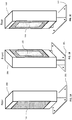
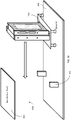
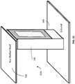
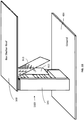
- Figures 1A to 1C show a display 100 with a forward-facing electronic display panel 102 and a choice of rear-facing display panels 103, 104, mounted on an optional plinth 101 that provides structural support to ground.
- the plinth 101 and associated fixings may be of variable structural qualities to meet the needs of the application e.g. to cater for high wind loading (horizontal forces) or high structural loading (vertical forces) for applications such as bus shelters loaded with snow.
- the plinth 101 may sit fully beneath ground or directly on top if there is sufficient strength in the ground construction.
- the rear-facing display panel 103 may be, for example, a static backlit poster panel or a scrolling backlit poster panel.
- the alternative rear-facing display panel 104 is an electronic display panel similar to the forward-facing electronic display panel 102.
- the electronic display panels 102, 104 are large-scale electronic display panels with a minimum visible screen size of approximately 50 inches (127 cm) and preferably 70 inches (178 cm) or more, measured diagonally across the screen.
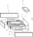
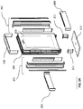
- a display may be formed from a front digital screen module 203 and a rear module 204 that may take various optional forms such as a blanking plate, a static backlit poster module or a scrolling backlit poster module.
- the front and rear modules 203, 204 are secured together by fixings 205 which in turn are fixed to plinth 101 by fixings 206.
- Customisable top, side and front claddings 200, 201 and 202 afford a desired external appearance to the display, with air filters 207 (for a cooling system) fitted prior to adding the side cladding 201; or accessible from the front when the glass door is opened.
- the outer cladding for the display may be standard, custom, branded, creative designed, cosmetic and of any type of material such as metal, wood, Corian, plastics, etc. It may be of varied height and shapes. It may be an extension of the environment that it is integrated with.
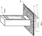
- Figure 4 illustrates a free-standing configuration of display 100, in which it is secured to plinth 101 that sits on solid foundations 401, such as concrete or a secure structure, established below ground level 400.
- Figure 5 illustrates an "integrated" configuration of display 100 in which the top of the display 100 is secured by a “dropper” 502 to the roof 500 of a bus stop that has a side 501 to provide structural support to the roof 500, which is also supported by the display 100.
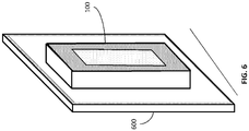
- FIG. 6 A wall-mounted configuration of display 100 is shown in Figure 6 , where the display is mounted in a structurally supported wall 600.
- Figures 7A to 7C show various styles of cladding 220 around display panel 102, which is disposed at differing heights above ground level 400, thereby giving different appearances to the display 100.
- the components of the claddings 220 are affixed around the display 100 by fixings at modular spacings, so that they may readily be interchanged with components of different looks and feel.
- Figure 8A shows a combined advertising display 800 constructed from a front digital electronic display module 203 and a rear display module 203 that may be, for example, a static backlit poster panel or a scrolling backlit poster panel.
- Figure 8B is a similar view of a double-sided (back-to-back) digital advertising display 801 constructed from two single digital screen modules 203 and 802.
- the rear display module 802 may be of generally the same configuration as the front display module 203.
- a heat-exchanger unit within the rear display module 802 for cooling purposes is oppositely handed, as compared to the front display module 203, such that air intakes 212 for the heat exchanger units of both of the modules 203, 802 are all at one common side of the display 801.
- Corresponding air outlets (not shown in Figure 8B ) for the heat exchanger units of both of the modules 203, 802 are located at a common, opposite side of the display 801. This ensures that 'dirty' air output from one of the display modules 203, 802 does not contaminate the 'clean' air input of the other of the display modules.
- Fan modules at the side of the display 800 may pump external air from external vents through the heat-exchangers, such that the hot air expels at the opposite side to the inlet side.
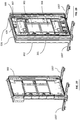
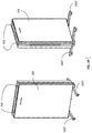
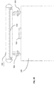
- Figure 9A is a front view showing internal components of digital display module 920 with a toughened glass door and LCD panel removed and Figure 9B is a side view of the display module 203 with the glass door 913 open and the LCD panel 915 brought forward.
- Typical components within the display module 920 without glass door are mounted within a metal chassis 900 and include a top environmental control unit 901, a top heat exchanger 902 and a top pair of circulating fans (919) made up of two top external fans 903.
- a top environmental control unit 901 At the lower end of the chassis 900 and provided a bottom heat exchanger 904, a bottom pair of circulating fans 918 made up of two bottom external fans 905 and a bottom environmental control unit 906.
- a router for controlling the display module 203 and providing data to and from it there are provided a router, an optional Ethernet switch, PC (Personal Computer or other processing device) 909, monitoring and control board 910 and Solid State Drive 911.
- PC Personal Computer or other processing device
- the PC or equivalent (909) may be mounted on a fold-out panel such that, in normal use, it is substantially flush with the surface of the heat-exchangers 902, 904 or other parts, but is folded out to access the PC for programming or service.
- Other components may be mounted in a similar manner.
- a bottom pair of circulating fans 918 and a top pair of circulating fans 919 are provided.
- the chassis 900 houses power supply assemblies 923. Such circulating fan modules and associated power supplies top and bottom of the unit circulate cool air across the front and rear of the LCD panel 915.
- An antenna 924 and a camera 925 are provided at the top of the chassis 900, along with a pair of external lifting and fixing ears 926.
- a respective gas strut 914 is provided at each side of the glass door 913, which is mounted on the chassis 900 by a hinge 931.
- a boss 930 on glass door 913 allows a strap with a bracket to slot over the boss 930 to assist lifting and securing of the LCD panel 915 to the glass door 913.
- the LCD panel 915 is supported on a bracket 917 that carries a video scaler, upscale and timing control 916 for the panel 915.
- the chassis 900 is mounted on a pair of C-brackets that are secured to a foundation plate 210 or other supporting surface that may be above or below ground level and may bridge utility pipe works, etc.
- Front and rear claddings 208, 209 cover the C-brackets 211.
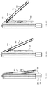
- FIGS 10A to 10C show sequential steps in the opening of the glass door 913, which pivots upwardly about the front door hinge 931.
- the hinge 931 is such as to move the glass door 913 forward, away from the chassis 900, as it pivots upwardly.
- the LCD panel 915 is brought forward with the glass door 913 as it pivots upwardly.
- the panel 915 is carried on the hinge 931 or other component such that it hangs down from the glass door 913, for ease of access for service or replacement. It will be appreciated that, in large-scale electronic displays, an LCD panel or the equivalent will generally be very heavy. Thus, affording ready access to the LCD panel 915 as illustrated in Figures 10A to 10C is very advantageous.
- Figures 10D and 10E are similar to Figures 10B and 10C but, in this case, the LCD panel 915 is secured to the glass door 913 by means of a bracket and strap 922 that engages with the boss 930 on the glass door 913. Therefore, as the glass door 913 opens by pivoting upwardly, the LCD panel 915 pivots upwardly with it, thus affording ready access to the interior of the chassis 900 to enable ready servicing of the components within it.
- the components of the display module are arranged in a modular fashion such that modules of various different functions can readily be accessed from the front of the chassis 900 and readily swapped for service or repair.
- a boss 930 and bracket and strap 922 may be provided on each side of the glass door 913, to secure the LCD panel 915 to the door 913.
- the glass door 913 may be open to an angle of about 45°, to afford access to the LCD panel 915 and/or to the inside of the chassis 900.
- the LCD panel 915 may be connected to components within the chassis 900 by one or more cables 921 that may readily be disconnected and reconnected, to allow the LCD panel 915 to pivot upwardly and/or to gain access behind the panel 915 to components or sub-assemblies within the chassis 900. Examples of such cables are as follows.
- the top environmental control sub-assembly 901 controls and monitors the top portion of the LCD backlight within the LCD display panel 915
- the bottom environmental control sub-assembly 906 controls and monitors the bottom portion of the LCD backlight within the display panel 915; using cabling such as ribbon cables and connectors such as D-type connectors, for example, which can be easily disconnected to allow the LCD panel 915 to be moved away from replaceable sub-assemblies located behind the LCD panel 915.
- the PC board 909 on board control sub-assembly 927 provides a video connection to the LCD display panel 915 using typical means such as an HDMI interface and associated cables and connectors, which can be easily disconnected to allow the LCD panel 915 to be moved away from replaceable sub-assemblies located behind the LCD panel 915.
- the monitoring and control board 910 on board the control sub-assembly 927 provides a communication connection to sensors on the display panel 915 using typical serial communication means such as I2C, CAN BUS etc and using associated cables such as ribbon cables and connectors such as IDC or D-Type connectors, which can be easily disconnected to allow the LCD panel 915 to be moved away from replaceable sub-assemblies located behind the display panel 915.
- typical serial communication means such as I2C, CAN BUS etc
- associated cables such as ribbon cables and connectors such as IDC or D-Type connectors
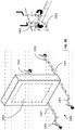
- FIG 11 a shows a transport jig 1100 that is formed on its upper surface with a recess adapted to receive a display module 1105 for transport.
- the transport jig 1100 is provided with wheels (which term includes rollers or casters) 1103 such that it can readily be rolled over a surface. It is also provided with a set of removable outriggers 1101, 1102 that are adapted to interengage with the transport jig 1100 and are provided with multidirectional casters, the heights of which may be adjusted in the manner of jockey wheels.
- the wheels 1103 on the transport jig 1100 itself may be of fixed or adjustable height.
- FIG 11B shows the display module 1105 and the outriggers 1101, 1102 engaged with the transport jig 1100.
- the heavy display module 1105 can readily be transported across a surface.
- item 1105 is initially a chassis with structural strength, for a display module to be assembled on the chassis.
- the chassis may conveniently be transported on the transport jig 1100, with or without the outriggers 1101, 1102 from a chassis supplier to a display manufacturing plant. In the manufacturing plant, the chassis is wheeled along a production line, with or without the outriggers 1101, 1102, where components (already in sub-assemblies where appropriate) are progressively fitted to the chassis, in order to form the display module.
- a completed display module 1105 may continue to be transported on the transport jig 1100, with or without the outriggers 1101, 1102, for both warehouse storage and subsequent transport and on-site installation.
- Figure 12A shows a set 1106 of display modules 1105 on respective outriggers 1100 and Figure 12B shows the transport jigs 1100 without the display modules 1105.
- the transport jigs 1100 taper from back to front and are adapted to nest with one another and/or interlock in order to minimise floor space and to enable more efficient storage of display modules 1105 in transport and in warehouse.
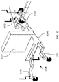
- a loaded transport jig 1104 with outriggers 1101, 1102 is shown navigating a raised kerb.
- the casters on the leading outriggers 1102 are respectively lowered and raised in order that a leading caster can mount the kerb, following which the adjacent caster is then raised, so that it too can mount the kerb.
- Figure 14 shows an end-to-end scalable digital display process 1400 from supply, through manufacture, storage and transportation to site, installation maintenance and ultimately de-installation.
- Figures 15 , 16A and 16B show steps of the process to a larger scale.
- step 1401 metalwork is supplied as chassis 900 mounted on a wheeled transport jig 1500 suitable for a manufacturing environment where there are no obstacles.
- step 1402 a number of chassis 900 mounted on respective transport jigs 1500 are transported in an upright position - e.g. on flatbed trucks, where they can be lifted on and off by simple lifting and passed directly to a production line. Shipping the chassis 900 from a supplier, already fitted to the transport jig 1500, can facilitate transportation from the outset.
- each chassis 900 on its respective jig 1500 is wheeled down the production line and populated with components / subassemblies from the front (i.e. accessed from the front of the chassis), starting with the rear components / assemblies etc and building up the assembly, working with successive components / assemblies from rear to front.
- each unit may progress on its transport jig 1500 from chassis 900 to assembled display module 920, without glass door, to completed display module 203 with glass door, to combined front and rear display modules 800.
- the components fitted to the chassis 900 may comprise heat exchange assemblies (top and bottom); fan assemblies (top, bottom, external) and associated ducting; environmental control assemblies (top, bottom); internal network; video circuits; main PC board; power monitoring & control board; battery; main power assemblies distributed (e.g. to provide local power for fans, LED backlighting strips etc); LCD panel; Glass door, etc., all supplied as modular replaceable sub-assemblies.
- step 1404 assembled display modules are transported to warehouse 1405 or directly to site in a way that maximise storage on the truck (or other transport means) and minimises handling of the display modules.
- the display modules can continue to be transported vertically on their jigs 1500 from initial supply at step 1401 to eventual installation at step 1406, obviating any reorientation of the heavy display modules.
- step 1405 assembled display modules are readily stacked on their transport jigs 1500 in such a way as to maximise floor space and storage capacity - for example, with nesting of the transport jigs as described above.
- Step 1406 indicates an on-site installation process, still using the same transport jig 1500 to position the display module in situ. Positioning of the display module is indicated at 1501. 1502 indicates a display module that has been installed at, for example, a bus stop shelter, with a display panel facing outwardly.
- Step 1407 indicates simple on-site maintenance by opening the glass door of the display module such that it brings an LCD panel forward in order to access and swap components and/or sub-assemblies within the chassis.
- 1503 indicates the front glass door opened.
- Step 1408 indicates a de-installation process, where a display module may be removed from site and, using a transport jig as before, returned to the warehouse for disposal or refurbishment.
- Figures 17 to 22 illustrate how a large-scale electronic display is installed as part of a bus stop or shelter, having a roof 500.
- a plinth 101 with upstanding support struts is fixed to foundations 401 (e.g. concrete) and the ground 400 is made good above the foundations 401.
- the plinth 101 may alternatively protrude or be bolted to a foundation laid above ground 400 - e.g. where there is a camber in the ground.
- a display 1105 is lifted off its transport (e.g. flatbed truck) using lifting ears 926 and lowered onto ground 400, still fixed to its wheeled transport jig 1100.
- the loaded transport jig 1104 is pushed towards the bus shelter roof 500 and the upstanding struts of the plinth 101.
- the transport jig may be tapered as described above, in order that it may fit between the struts of the plinth 101.
- Figure 19 corresponds to item 1501 in Figure 14 .
- Figure 20 shows a double-sided digital display 800 secured to the upstanding struts of the plinth 101 by fixings 206, with the transport jig then removed, after which it may be returned for re-use as part of the manufacturing flow, eliminating the need for specialist installation equipment - e.g. suction equipment such as Gekos.
- specialist installation equipment e.g. suction equipment such as Gekos.
- the display can be directly lifted and fixed to the struts of the plinth 101 using standard lifting gear (e.g. HIAB), without the need for the transport jig once the display has been unloaded.
- standard lifting gear e.g. HIAB
- FIG 21 which corresponds to item 1502 of Figure 14 , top, side and front cladding is fitted for cosmetic appearance.
- easily changed and cleanable air filters are located between the cladding and the cooling system of the display, which filters can be cleaned by low-skilled operatives as part of a cleaning process, without opening the glass door of the display.
- the display is secured to the bus shelter roof via a 'dropper', such that the display 100 provides structural support for the bus shelter.
- any cladding for any creative "look and feel" can be fitted to the display, using a modular fixing system.
- any rear display module can be supported, including a configuration of two back-to-back digital screens, which may be fitted together on-site or as part of the manufacturing process.
- digital LCD panel 915 faces inwardly with respect to the bus shelter.
- a rear advertising poster may be changed as required - e.g. typically on a two-week cycle.
- Glass door 913 of display 100 may be opened upwardly to bring the LCD panel 915 forward, either connected to the glass door 913 to facilitate access within the chassis of the display for servicing and swapping components and modules within; or left to hang from the glass door 913 or its hinge, to facilitate access to the LCD panel 915 for service or exchange.
- digital LCD panel 915 may face outwardly with respect to the bus shelter.
- FIGS 23 to 41 illustrate alternative design features of large-scale electronic displays.
- Display 100 in Figure 23 is mounted on C-brackets 211 to support the display 100 on foundation plate 210.
- Front and rear plinth cladding is 208, 209 cover the C-brackets 211.
- Lifting and fixing ears 926 are provided on the top of the display 100, along with an antenna 924.
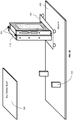
- Figure 24 shows the display 100 in exploded view, similar to Figure 3 , with customisable top cladding 200 and side cladding 201.
- the display comprises a front digital panel module 203 and rear module 204 that can be of any desired configuration.
- Figure 25 shows display chassis 900 above a pair of skids 1007 that carry wheels, rollers or casters.
- the chassis 900 is secured to the skids 1007 by C-brackets or other fixing means.
- the wheeled skids 1007 thus provide a wheeled transport jig (1000) for transport of the chassis 900 and subsequently assembled display.
- Figure 26 is a view similar to Figure 15 , like reference numerals indicating like or corresponding parts, illustrating stages of manufacture, during which chassis 900 is populated with components and/or sub-assemblies as it is wheeled along a production line on the wheeled skids.
- 927 indicates a control assembly - for example including a PC or equivalent (909), monitoring and control board (910) and solid-state memory device (911). Also shown is a battery assembly 928.
- Figures 27 and 28 are perspective views from Figure 26 , to a larger scale.
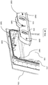
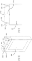
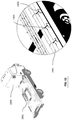
- FIG. 29 shows a curved slot 932 formed in the surround of glass door 913.
- the slot 932 is open at its left side and closed at its right side, as seen.
- the slot 932 receives a stud (not shown) on support bracket (917) of LCD panel 915 such that the LCD panel 915 may be freely suspended from the door 913.
- the stud is firstly introduced into the left side of the slot 932 as seen, raised slightly and then dropped down the right side of the slot 932 as seen, where the weight of the LCD panel 915 retains the stud in the slot 932.
- a slot 932 is provided at each side of the door 913, with respective studs provided on the support bracket of the LCD panel 915 or other associated part.
- the studs allow the LCD panel 915 to pivot with respect to the door 913, so that the LCD panel may hang freely (as in Figures 10B and 10C , for example) or pivot upwardly with the door 913 (as in Figures 10D and 10E , for example).
- Figure 30 shows the glass door hinge 931 in a closed position (at the left side as seen) and in successive stages of opening. In the interests of clarity, the door itself is not shown.
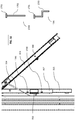
- the hinge 931 comprises a parallel linkage in which the outer end of a main support arm 935, which is connected to the door surround or an associated part, is arranged to pivot upwardly as the hinge opens and come forward as it does so.
- a secondary support arm 936 is pivotally connected at one end to the main support arm 935 and its other end is constrained to move vertically in a slideway 938.
- Three pivotal links 937 each have one end constrained to move vertically in the slideway 938, one of the pivotal links 937 having its opposite end pivotally connected to the main support arm 935 and the other two pivotal links 937 having their opposite ends pivotally connected to the secondary support arm 936.
- the inner end of the main support arm 935 moved downwardly a little, as the outer end of the main support arm 935 pivots upwardly and moves outwardly.
- FIG 31 shows further detail of the opening glass door 913 with LCD panel 915 hanging from it.
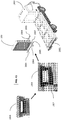
- the LCD support bracket 917 at each side of the LCD panel 915 is formed with a pair of keyhole slots 1700 with which the heads 1701 of handles 1704 or 1705 are removably engaged, the handles having respective shanks 1702, 1703 of alternative configurations.
- four handles 1704, 1705 may be used to lift the LCD panel 915 into and out of position without needing to touch or mark the front of the LCD panel 915.
- this facilitates engaging the LCD panel 915 with the door 913, hanging the panel 915 in its operative position, removing it from that position, or latching the panel 915 to the door 913 for access within the display chassis.
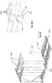
- FIG 32 illustrates a novel arrangement for mounting one of more cooling fan.
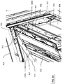
- an upper pair of circulating fans 919 are housed in a fan box 1800 that has a pair of apertures to engage with two pillars 1801 that are mounted on the front door 913 or an associated part.
- the fan box 1800 is secured in place by a pair of clips 1802 that engage with end portions of the pillars 1801.
- a third clip 1802 engages with a corresponding fastening on the front door 1803, between the two fans 919.
- the fan box 1800 forms a sub- assembly that is readily secured to the front door 913 assembly, in a space above the LCD panel 915.
- the fan box 1800 pivots upwardly with it, thereby affording improved access to components or sub- assemblies within the display chassis - e.g. router 907 - for maintenance or replacement. It will be appreciated that the fan box 1800 itself may readily be removed from the front door 913 assembly, for maintenance or replacement.
- Figure 33 is a perspective view looking upwards into the display with the front door 913 open, showing the fan box 1800 above the LCD panel 915.
- a door seal 1803 is shown in Figure 32 .
- the door 913 is subjected to a degree of translational movement, forwardly away from the display chassis, as it is pivoted upwardly to open.
- the door 913 is pivoted downwardly to close, it is also subjected to a degree of translational movement, backwards towards the chassis, thereby applying a relatively uniform pressure to the door seal 1803 to ensure a good seal to the interior of the display.
- Figure 34 shows display 100 carried on a pair of wheeled skids 1007 and provided with a pair of fixing and lifting ears or lugs 926.
- Figure 35 is a view similar to Figure 13 , showing a loaded transport jig 1004 with a display 1005 under transportation, the wheeled skids 1007 affording the transport jig in this case, provided with outriggers 1001, 1002 with casters of adjustable height, which can be engaged with and detached from the wheeled skids 1007.
- Figure 36 illustrates a novel device for lifting a display 100 and installing it under an obstacle such as a bus shelter roof 500.
- the device as a C-lift frame 1650 as it is generally of C-shape. It comprises a generally upright frame 1651 that supports a telescopic upper arm 1652 and a pair of telescopic lower forks 1655 that are joined by a brace 1656.
- a counterbalance weight 1654 is mounted at an end of the upper arm 1652.
- a lifting point 1653 is provided on the upper arm 1652 and may take the form of a lifting eye, U-bolt and/or loop for attachment to lifting equipment - for example a HIAB, small crane or any other suitable means.
- the lifting forks 1655 are attached to the lifting ears 926 on the display 100 and lifting equipment lifts the display 100 via the C-lift frame 1650, the weight and position of the counterbalance 1654 being suitably adjusted to ensure that the forks 1655 remain substantially horizontal and the display 100 remains substantially upright.
- the C-lift frame 1650 can then be manoeuvred via the lifting equipment until the display 100 is in a required position beneath the bus shelter roof 500, which is accommodated in the space between the upper arm 1652 and the lower forks 1655 of the C-lift frame 1650.
- the display 100 is lowered gently until it is supported on its skids 1007, which in turn are supported by means appropriate to the particular installation, an example of which follows.
- the C-lift frame 1650 can then be disconnected from the display 100 and removed out of position by the lifting equipment.
- FIG 37 illustrates a display 100 mounted on skids 1007 to which jacks 1008 are removably attached. It may be assumed that the display 100 has just be manoeuvred under a bus shelter roof with the aid of the C-lift frame 1650.
- the display 100 is supported on the skids 1007 that in turn are supported by jacks 1008 that in turn are supported on ground surrounding an excavation in which foundation plate 210 with C-brackets 211 attached has been laid.
- the display 100 is lowered onto and fixed to the top of the C-brackets 211 using fixing bolts or other means, which are in turn fixed to the foundation plate 210.
- the dropper 502 is fixed to the fixing ears 926 using fixing bolts.
- the jacks 1008 raise the height of the display 100, C-Brackets 211 and foundation plate 210, allowing the dropper 502 to be fixed to the bus shelter roof 500, where the entire structure is supported on the jacks 1008.
- Concrete is poured into the foundations to fill the gaps and secure the foundation plate 210 and C-brackets 211 into the foundations.
- the skids 1007 and jacks 1008 can be removed and returned to the factory or warehouse for re-use. Where necessary the skids 1007 can be extended to bridge the foundation hole, allowing the jacks to safely support the structure until the concrete has set.
- This method allows the display, foundations and associated C-brackets and foundations plates to be perfectly aligned with the fixed bus shelter fixing points whilst the concrete sets, eliminating any misalignment between foundations and bus shelter roof.
- the bus shelter can be temporarily supported e.g. using an Acrow prop, the dropper 502 removed, the display 100 fixed to and supported by the C-lift frame 1650, the display unfixed from the C-brackets 211 and then lifted from beneath the bus shelter.
- the skids 1007 can then be refit to the display 100 ready for transportation back to the factory or warehouse using a transport means such as a flatbed truck.
- a replacement display 100 can be lifted and positioned under the bus shelter roof 500 using a C-lift frame 1650 and fixed to both the stable C-brackets 211 and bus shelter rood 500 using the dropper 502 in the knowledge that the foundation fixings are perfectly aligned with bus shelter fixings as a result of previous methods.
- the steps outlined above with reference to Figures 37 and 38 are not confined to use for installation of displays 100 under obstructions such as bus shelter roof is 500. If there is no such obstruction, the C-lift frame 1650 does not have to be employed and the display 100 can be positioned over an excavated foundation, utilising lifting ears 926 and/or skids 1007 and/or jacks 1008.
- the skids 1007 and jacks 1008 may also be used where the foundation is not excavated, for convenient positioning of the display 100 with respect to its various fixings.
- the display 100 may conveniently be raised to meet a bus shelter roof 500 or other structure above it, to which it may be secured.
- Skids 1007 may be of different lengths for different installations. However, they may conveniently be of a standard length suitable for most purposes, with optional extension pieces to extend the distance between the skids 1007 and jacks 1008 and/or outriggers 1001, 1002.
- Figure 39 illustrates fixings between a display 100 and a bus shelter roof 500.
- a 'dropper' 502 is secured to the fixing ears 926 at the top of the display 100 by nuts and bolts or other suitable means and also to the bus shelter roof 500 by nuts and bolts or other suitable means.
- FIGS 40 and 41 illustrate a 'top box' that may provide a top cladding to a screen 100 of freestanding configuration, without a structure such as a bus shelter roof above it.
- the top box 1600 has fixing ears 1601 that are located adjacent the fixing ears 926 at the top of the display 100, the ears 926 passing through slots in the base of the top box 1600.
- the fixing ears 1601 and 96 are secured together by nuts and bolts or other securing means.
- An antenna extension cable 1602 passes through a sealing grommet at the top of the display 100 and connects to antenna 924 on top of the top box 1600 via a hole in the bottom of the top box 1600.
- the top box 1600 has front and rear panels that can be opened to gain access to components or fixings inside.
- FIG. 42 to 48 A novel transport system for displays is illustrated in Figures 42 to 48 .
- Figure 42 shows a transport frame base (module) 1901 that is secured to a flat load bed of a lorry (truck) 1900.
- the transport frame base 1901 may be used as a single item - for example, on a small flatbed lorry - or cascaded with other similar modules - for example, three modules can be used on an articulated lorry.
- the transport system can also be used on other transport vehicles, vessels or devices.
- the load bed of the truck 1900 is provided with a series of anchor points 1902 - typically along the edges of the load bed.
- the transport frame base 1901 is secured to the anchor points 1902 by fixings 1903 - for example, turnbuckles, chains, straps, etc.
- a display 100 to be transported is mounted on skids 1007, to each of which is fitted a fork bracket 1904 at or adjacent a respective end of the skid 1007.
- Each of the fork brackets 1904 is formed with an aperture to receive a fork 1905 of a forklift truck.
- each of a pair of lifting forks 1905 engages with two fork brackets, one on each of the skids 1007, so that the forklift truck can readily lift and transport the display 100, mounted on the skids 1007.
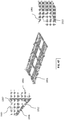
- the transport frame base 1901 comprises a plurality of parallel rails 1906 that are secured to the frame base 1901 in pairs.
- the rails 1906 are of open channel or U-section, as seen.
- the rails 1906 are arranged in two spaced sets of three, one set on the left side and the other set on the right side of the frame base 1901, as seen.
- the figure shows a single display 100 mounted on its skids 1007, which are secured respectively to the right most rail 1906 of each set of three, as seen.
- each rail 1906 is formed with pairs of opposite holes at modular intervals, to receive fixing pins 1911 (e.g. clevis pins) that secure the bottom part of a skid bracket 1909.
- the upper part of the skid bracket 1909 is secured to an end of a respective skid 1007, by means of another fixing pin 1911 that passes through a pair of opposite holes at the respective end of the skid 1007, as shown in Figure 44A .
- An upright frame 1907 is secured at one end of the frame base 1901 and held by cross braces 1910. Further braces 1908 are secured between the top of the upright frame 1907 and the fixing ears 926 at the top of the display 100.
- the display 100 as shown in Figure 44 , is secured firmly on the transport frame base 1901 and by the upright frame 1907, the transport frame base 1901 being secured firmly in turn on the load bed of the respective transport vehicle or device.
- the remaining pairs of rails 1906 may then be used to mount and secure additional displays.
- the skids 1007 of a second display 100 may be mounted on the centre rails 1906 of each set of 3, such that the second display is disposed slightly behind and to the left (as seen) of the first display 100. This effectively nests the skids 1007 under the displays 100, to minimise the footprint required to load multiple displays 100 and maximise packing density on the transport.
- a further display 100 may then be mounted in a similar way behind the second display, slightly behind and to the left of it, with the respective skids 1007 being mounted on the leftmost rails 1906 (as seen) of the sets of three.
- a fourth display 100 may then be mounted behind the third display, again using the right most rails 1906 (as seen) of each set of three, so that the fourth display is lined up behind the first display - and so on.
- Figure 45 illustrates such an arrangement, with 4 displays 100 mounted on the transport frame base 1901, one behind the other, with each two successive displays laterally offset.
- Braces 1908 secure the tops of the displays 100 to the top of the upright frame 1907. Where two displays 100 are in alignment, as with the first and fourth displays, successive braces 1908 may be joined at fixing ears 926, as shown in Figure 45 , where a fixing pin 1911 secures the respective ends of two successive braces 1908 at a fixing ear 926 of the first display 100.
- an additional upright frame 1907 is secured part way along the frame base 1901, with braces 1910 to secure the upright frame 1907 and with upper braces 1908 secured to the top of the upright frame 1907.
- the displays 100 are formed into a secure block that cannot fall via a "domino effect" during transportation.
- the load of displays 100 can move only as a whole rather than as individual elements.
- the frame base 1901 is preferably of modular design such that it can be cascaded with other similar units.
- male connectors 1912 and female connectors 1913 are provided at the ends of the frame base 1901 and are adapted to interconnect in order to secure adjacent frame bases 1901 together.
- Figure 48 shows an arrangement in which 3 transport frame bases 1901 have been interconnected and to end and secured to the load bed of an articulated lorry 1900.
- Displays 100 are secured to the frame bases 1901 and upright frames 1907 as described above, to form an integrated load for transport.
- space is provided for a pallet to transport supplementary fixings - e.g. C-brackets, plinths, cladding, etc.
- one or more displays 100 may be detached from the frame base 1901 and upright frame(s) 1907 and lifted down from the load bed for installation at the respective site.
- the fork brackets 1904 may be removed from the skids 1007 and, if they have previously been removed or retracted, wheels, rollers, casters, etc may be redeployed on the skids 1007 - and/or wheeled outriggers may be attached to the skids 1007, to assist as may be required in the respective installation process.
- Improved access is provided to electronics components and assemblies behind an LCD panel to facilitate easy swap out; without having to provide mechanisms to rotate the screen away from obstacles (e.g. wall) and gain entry from rear panels that require removal of rear advertising assemblies e.g. lighting strips.
- obstacles e.g. wall
- rear advertising assemblies e.g. lighting strips.
- Flexibility of design is afforded, with mechanisms to quickly tailor mass produced assemblies into customer and application specific screens quickly, with the ability to mount freestanding, wall mounted or as part of existing structures without creating fully bespoke designs.
- a scalable electronic display apparatus combined with a scalable mass process is key for reducing the total cost of ownership for both the advertising screen operator and the screen supplier (who may wrap up the maintenance service into a rental model).
- large outdoor screens e.g. 60 inch (152 cm) or more are extremely large, bulky and heavy and as a minimum they exceed 100kg in weight and typically greater than 250Kg. This is as a result of the structure, weather-proofing, temperature extremes for the environment, and also to ensure audience viewability from long distances in direct sunlight.
- Examples of the invention may provide a large outdoor advertising screen module that can be quickly and easily tailored to meet varying client and market needs that change on an ongoing basis, by enabling the module to be mounted, clad and integrated in different ways through attached modular accessories; in a way that can be mass produced for low cost and high volume. Furthermore they adopt features that ease serviceability and maintenance such that the cost of ownership is reduced over the lifetime of the product.
- the modular end products created are mass produced through a method that spans the life cycle of the module / end products including component supply, manufacture, warehouse, transportation, on-site installation, maintenance and de-installation.
- Illustrated in the example of Figure 14 is a method or process of manufacturing a large-scale electronic display having a given orientation, comprising the steps of constructing a chassis to provide structural strength for the display; mounting the chassis on a transport jig; conveying the chassis on the transport jig to an assembly line; moving the chassis on the transport jig along the assembly line; and fitting components for the display to the chassis as it is moved along the assembly line: wherein the chassis is maintained in an orientation corresponding to the given orientation of the display from the time that is mounted on the transport jig until the time that assembly of the display is completed on the assembly line.
- the desired electronic display end goods are manufactured by successively assembling components, sub-assemblies and modules down a production line; where the process can be extended to simplify the complete product life cycle from supply of key components through to installation and ongoing maintenance.
- key large source assemblies may be prepared and transported with sub-systems and components in a suitable way and using jigs/bogies that minimise handling and dovetail with manufacturing process to simplify and reduce costs.
- the product is transported and handled using the re-useable jigs / bogies with suitable "accessories / attachments" that simplify the on-site installation.
- the unit is transported along the production line upright, as it remains throughout storage, shipment and final installation.
- the display in manufacture is successively wheeled on the bogie down the production line for assembly, then test, then to a transportation area; where wheels maybe optionally removed from the bogie and the entire screen assembly (including stable base) lifted onto vehicle for transport to a warehouse.
- the screen assembly will be lifted, placed on the ground and wheeled jigs attached to the base plates to aid moving the screen assembly into positioned on the plinth, where there is sufficient movement in the jig to traverse and manoeuvre around obstacles such as kerbs, pavements, slopes, bollards, bins ... or under canopies providing restricted head height e.g. forecourt or shop canopies.
- the transport jigs may provide additional stability for transporting more than one unit.
- the transport jigs may allow one or two displays to be built upon the jigs by moving the jig between two parallel manufacturing lines.
- Handling can be simplified at each stage since there is no need to change the orientation of the display throughout the whole process, e.g. by simply moving the screen on its "bogie” or jig with supplementary aid from relatively simple, traditional lifting equipment such as a crane (within manufacturing plant) or HIAB (at the point of installation); eliminating the multiple site visits of heavy assemblies as associated with previously proposed approaches.
- a crane within manufacturing plant
- HIAB at the point of installation
- Two parallel manufacturing lines allow two screen assemblies to be bolted to a common plate/bogie/transport jig and assembled together as they pass between the two process lines - resulting in the two screens being fixed together at bottom and top, to add improved stability for subsequent transport.
- Air flow is arranged horizontally across the unit such that air intake filters can be easily cleaned or replaced by non-skilled workers without opening the main unit or having to work at heights in busy locations (as is the case for previously proposed vertical cooling arrangements where air intake is located at the top of the unit).
- Serviceability of the display may be facilitated through a front glass door that comprises glass bonded directly to a frame (not replaceable glass) such that the entire glass door can be replaced, rather than just the glass.
- Prior art has glass door assemblies (replaceable glass) opening hinged from the top using a fixed hinge; or by bolting the glass door assembly evenly around the seals e.g. as with a 'LCD Cartridge' approach.
- Bolted glass assemblies require many bolts to be opened making it time consuming; furthermore, once re-attached care has to be taken to apply even pressure to ensure the seals are not damaged
- opening mechanism utilises a cantilever hinge, which brings the glass door assembly forward and away from the frame as it opens, due to the parallelogram action of the hinge.
- prior art shows glass assemblies being using for advertising screens; where the glass is separate and replaceable to the door frame; for use where the glass breaks and can be replaced easily. It also shows glass bolted with many bolts in order to provide a secure seal which is difficult and time consuming to open.
- Glass can be bonded directly to the frame such that it is not replaceable, where the frequency / probability of it getting damaged makes it worthwhile bonding as one unit such that the glass door can be opened easily. However, where the glass is broken then the cost of replacing the glass door is expensive.
- Hammerglass a polycarbonate material with a silicon oxide (glass) surface (developed by www.hammerglass.com) is a durable abrasion-resistant polycarbonate sheet, 300 times stronger than glass and virtually unbreakable. It is 40% lighter than glass, making it easier to handle.
- the frame to which the glass (or alternative) is bonded to does not need to be metal.
- it could be Glass Re-enforced Plastic (GRP), fibreglass etc in order to reduce the weight of overall weight of the door.
- GRP Glass Re-enforced Plastic
- the layers of toughened plastics sheet and attached film could be arranged to be replaced and fixed into a glass assembly as per prior art, or could be bolted to a frame through holes in the toughened plastics sheet where seals are made as the bolts are tightened.
- this provides a cost effective, light weight, easy to work with solution that helps reduce cost an aid mass scalability of large outdoor advertising screens.
- the figures illustrate two displays back-to-back to provide a digital advertising screen on both front and rear. Appropriate cladding will give the appearance that this is just one unit.
- Heat exchangers can be placed to force air flow to go either left-to-right or right-to-left within each module. This enables two front display modules to be positioned back-to-back as a single combined module, and arranged such that the external air intake on both modules is on the same (common) side; as well as the exhaust outlets also being on the same but opposite side. This ensures that the dirty air output from one display does not contaminate the clean air input of the displays.
- the LCD panel and the box formed by the chassis are typically rectangular, but could be other shapes.
- LCD panels are mentioned primarily, the invention applies equally to display panels utilising other technology, e.g. LED or plasma.
Landscapes
- Physics & Mathematics (AREA)
- Engineering & Computer Science (AREA)
- General Physics & Mathematics (AREA)
- Theoretical Computer Science (AREA)
- Nonlinear Science (AREA)
- Chemical & Material Sciences (AREA)
- Crystallography & Structural Chemistry (AREA)
- Optics & Photonics (AREA)
- Mathematical Physics (AREA)
- Multimedia (AREA)
- Signal Processing (AREA)
- General Engineering & Computer Science (AREA)
- Mechanical Engineering (AREA)
- Devices For Indicating Variable Information By Combining Individual Elements (AREA)
Claims (15)
- Dispositif d'affichage électronique à grande échelle possédant un boîtier, une porte transparente à l'avant du boîtier et un panneau d'affichage derrière la porte, ladite porte étant raccordée au boîtier par un mécanisme de charnière qui assure le pivotement de la porte vers le haut pour ouvrir et vers le bas pour fermer et aussi un mouvement de translation de la porte en l'écartant du boîtier tandis que la porte est ouverte et vers le boîtier tandis que la porte est fermée, pour appliquer une pression de fermeture autour de la porte lorsqu'elle est fermée et le panneau d'affichage étant raccordé à la porte, au mécanisme de charnière ou à une partie raccordée à la porte ou au mécanisme de charnière, de sorte que le panneau d'affichage soit aussi déplacé en s'écartant du boîtier avec la porte à mesure qu'elle s'ouvre et de sorte que le panneau d'affichage soit suspendu à la porte, au mécanisme de charnière ou à une partie raccordée à la porte ou au mécanisme de charnière lorsque la porte est ouverte.
- Dispositif d'affichage électronique à grande échelle selon la revendication 1, ledit panneau d'affichage étant raccordé à la porte en se mettant en prise mutuellement avec des fentes et des goujons, de sorte que le panneau d'affichage puisse pivoter par rapport à la porte.
- Dispositif d'affichage électronique à grande échelle selon l'une quelconque des revendication 1 ou 2, comprenant en outre un élément de fixation libérable pour fixer le panneau d'affichage à la porte afin qu'il pivote avec la porte à mesure qu'elle est ouverte et fermée ou, lors de la libération de l'élément de fixation, la porte est suspendue à la porte, au mécanisme de charnière ou à une partie raccordée à la porte ou au mécanisme de charnière lorsque la porte est ouverte.
- Dispositif d'affichage électronique à grande échelle selon la revendication 1, 2 ou 3, ledit panneau d'affichage étant raccordé de manière libérable à la porte, au mécanisme de charnière ou à une partie raccordée à la porte ou au mécanisme de charnière, de sorte que le panneau d'affichage puisse être enlevé et remplacé.
- Dispositif d'affichage électronique à grande échelle selon l'une quelconque des revendications précédentes, comprenant en outre au moins un vérin à gaz pour supporter la porte à mesure qu'elle est ouverte.
- Dispositif d'affichage électronique à grande échelle selon l'une quelconque des revendications précédentes, comprenant en outre un ou plusieurs raccords détachables qui fournissent des raccords électriques entre le panneau d'affichage et des composants dans le boîtier, de sorte que le désengagement du ou de chaque raccord assure un mouvement d'ouverture suffisant de la porte et du panneau pour assurer un accès aux composant dans le boîtier permettant la maintenance.
- Dispositif d'affichage électronique à grande échelle selon l'une quelconque des revendications précédentes, comprenant en outre des poignées qui peuvent être fixées de manière détachables aux côtés du panneau d'affichage afin de supporter le panneau d'affichage tandis qu'il est déplacé dans sa position de fonctionnement ou hors de celle-ci.
- Dispositif d'affichage électronique à grande échelle selon l'une quelconque des revendications précédentes, ledit boîtier comprenant une boîte ouverte à l'avant conférant une résistance structurelle au dispositif d'affichage ; des composants étant montés dans la boîte pour la fourniture d'une alimentation électrique et de signaux au panneau d'affichage, de sorte que tous lesdits composants soient accessibles depuis l'avant de la boîte lorsque la porte est ouverte ; et ladite boîte possédant des points de fixation pour des éléments de chemisage autour de la périphérie de la boîte.
- Dispositif d'affichage électronique à grande échelle selon l'une quelconque des revendications précédentes, un second dispositif d'affichage faisant face vers l'arrière étant monté au niveau de l'arrière du boîtier.
- Dispositif d'affichage électronique à grande échelle selon la revendication 9, ledit second dispositif d'affichage comprenant une affiche statique ou de défilement.
- Dispositif d'affichage électronique à grande échelle selon la revendication 9, ledit second dispositif d'affichage comprenant un dispositif d'affichage électronique à grande échelle supplémentaire.
- Dispositif d'affichage électronique à grande échelle selon l'une quelconque des revendications précédentes, des sous-ensembles modulaires remplaçables étant accessibles depuis l'avant du boîtier lorsque la porte a été ouverte, lesdits sous-ensembles comprenant l'un ou plusieurs d'un sous-ensemble de commande de dispositif d'affichage ; d'un sous-ensemble de régulation de conditions ambiantes ; d'un sous-ensemble de batterie ; d'un sous-ensemble de routeur ; d'un sous-ensemble de ventilateur ; d'un sous-ensemble d'alimentation ; d'un sous-ensemble de boîte de ventilateur ; d'un sous-ensemble de caméra ; d'un sous-ensemble de panneau d'affichage ; d'un sous-ensemble vidéo.
- Dispositif d'affichage électronique à grande échelle selon l'une quelconque des revendications précédentes, ladite porte transparente comprenant une feuille de matériau polycarbonate avec un revêtement externe d'oxyde de silicium, ladite feuille étant liée au cadre externe.
- Dispositif d'affichage électronique à grande échelle selon la revendication 13, comprenant en outre au moins un film externe qui fournit des caractéristiques de gain anti reflet, anti-graffiti et/ou anti-solaire sur ledit revêtement externe.
- Dispositif d'affichage électronique à grande échelle selon la revendication 14, ledit film externe étant amovible et remplaçable.
Applications Claiming Priority (2)
| Application Number | Priority Date | Filing Date | Title |
|---|---|---|---|
| GB201423233 | 2014-12-24 | ||
| PCT/GB2015/054168 WO2016102981A1 (fr) | 2014-12-24 | 2015-12-24 | Afficheurs électroniques à grande échelle et procédés pour leur fabrication |
Publications (2)
| Publication Number | Publication Date |
|---|---|
| EP3238440A1 EP3238440A1 (fr) | 2017-11-01 |
| EP3238440B1 true EP3238440B1 (fr) | 2018-11-28 |
Family
ID=55237677
Family Applications (2)
| Application Number | Title | Priority Date | Filing Date |
|---|---|---|---|
| EP15828838.1A Active EP3238440B1 (fr) | 2014-12-24 | 2015-12-24 | Afficheurs électroniques à grande échelle |
| EP15828837.3A Active EP3238439B1 (fr) | 2014-12-24 | 2015-12-24 | Procédés de fabrication d'afficheurs électroniques à grande échelle |
Family Applications After (1)
| Application Number | Title | Priority Date | Filing Date |
|---|---|---|---|
| EP15828837.3A Active EP3238439B1 (fr) | 2014-12-24 | 2015-12-24 | Procédés de fabrication d'afficheurs électroniques à grande échelle |
Country Status (3)
| Country | Link |
|---|---|
| EP (2) | EP3238440B1 (fr) |
| GB (3) | GB2535841B (fr) |
| WO (3) | WO2016102981A1 (fr) |
Cited By (1)
| Publication number | Priority date | Publication date | Assignee | Title |
|---|---|---|---|---|
| RU194625U1 (ru) * | 2019-09-17 | 2019-12-17 | Андрей Борисович Чегуров | Устройство индивидуального назначения участника массового общественного мероприятия |
Families Citing this family (67)
| Publication number | Priority date | Publication date | Assignee | Title |
|---|---|---|---|---|
| US8854595B2 (en) | 2008-03-03 | 2014-10-07 | Manufacturing Resources International, Inc. | Constricted convection cooling system for an electronic display |
| US12185512B2 (en) | 2007-11-16 | 2024-12-31 | Manufacturing Resources International, Inc. | Electronic display assembly with thermal management |
| US8773633B2 (en) | 2008-03-03 | 2014-07-08 | Manufacturing Resources International, Inc. | Expanded heat sink for electronic displays |
| US8654302B2 (en) | 2008-03-03 | 2014-02-18 | Manufacturing Resources International, Inc. | Heat exchanger for an electronic display |
| US8497972B2 (en) | 2009-11-13 | 2013-07-30 | Manufacturing Resources International, Inc. | Thermal plate with optional cooling loop in electronic display |
| US10827656B2 (en) | 2008-12-18 | 2020-11-03 | Manufacturing Resources International, Inc. | System for cooling an electronic image assembly with circulating gas and ambient gas |
| US8749749B2 (en) | 2008-12-18 | 2014-06-10 | Manufacturing Resources International, Inc. | System for cooling an electronic image assembly with manifolds and ambient gas |
| KR101868077B1 (ko) | 2012-10-16 | 2018-06-18 | 매뉴팩처링 리소시스 인터내셔널 인코포레이티드 | 전자 디스플레이용 후방 팬 냉각 어셈블리 |
| WO2014150036A1 (fr) | 2013-03-15 | 2014-09-25 | Manufacturing Resources International, Inc. | Système de refroidissement pour un dispositif d'affichage électronique |
| WO2015006335A2 (fr) | 2013-07-08 | 2015-01-15 | Manufacturing Resources International, Inc. | Système de refroidissement en boucle fermée formant le chiffre huit pour un affichage électronique |
| EP3138372B1 (fr) | 2014-04-30 | 2019-05-08 | Manufacturing Resources International, INC. | Ensemble d'affichage électronique dos à dos |
| US9723765B2 (en) | 2015-02-17 | 2017-08-01 | Manufacturing Resources International, Inc. | Perimeter ventilation system for electronic display |
| US10820445B2 (en) | 2016-03-04 | 2020-10-27 | Manufacturing Resources International, Inc. | Cooling system for double sided display assembly |
| CN106847138A (zh) * | 2017-03-07 | 2017-06-13 | 刘峰 | 一种可清理雾霾的广告牌 |
| WO2018200905A1 (fr) | 2017-04-27 | 2018-11-01 | Manufacturing Resources International, Inc. | Système et procédé permettant d'empêcher un gauchissement de dispositif d'affichage |
| US10485113B2 (en) * | 2017-04-27 | 2019-11-19 | Manufacturing Resources International, Inc. | Field serviceable and replaceable display |
| GB2561894B (en) * | 2017-04-28 | 2019-10-16 | Amscreen Group Ltd | Environment control in electronic displays |
| GB201706770D0 (en) * | 2017-04-28 | 2017-06-14 | Amscreen Group Ltd | Control of electronic displays |
| GB2561893B (en) | 2017-04-28 | 2020-04-15 | Amscreen Group Ltd | Environment control in electronic apparatus |
| GB2561895B (en) * | 2017-04-28 | 2019-10-16 | Amscreen Group Ltd | Cooling of electronic displays |
| CN107231516A (zh) * | 2017-07-27 | 2017-10-03 | 重庆万建电子工程有限责任公司重庆第分公司 | 带刮灰结构的半球型摄像机 |
| US10559965B2 (en) | 2017-09-21 | 2020-02-11 | Manufacturing Resources International, Inc. | Display assembly having multiple charging ports |
| US10602626B2 (en) | 2018-07-30 | 2020-03-24 | Manufacturing Resources International, Inc. | Housing assembly for an integrated display unit |
| US10466749B1 (en) * | 2018-09-26 | 2019-11-05 | Apple Inc. | Peripheral housing for a computing device |
| US11096317B2 (en) | 2019-02-26 | 2021-08-17 | Manufacturing Resources International, Inc. | Display assembly with loopback cooling |
| US10795413B1 (en) | 2019-04-03 | 2020-10-06 | Manufacturing Resources International, Inc. | Electronic display assembly with a channel for ambient air in an access panel |
| CN110031603B (zh) * | 2019-05-10 | 2023-10-03 | 四川省科源工程技术测试中心有限责任公司 | 页岩解吸气实时监控装置 |
| US10665138B1 (en) | 2019-07-09 | 2020-05-26 | Retail Solution Center | Cosmetic display assembly |
| US11496091B2 (en) | 2019-08-27 | 2022-11-08 | Manufacturing Resources International, Inc. | Electronic display assemblies with solar panels |
| US11285895B2 (en) | 2019-08-27 | 2022-03-29 | Manufacturing Resources International, Inc. | Solar powered vehicle mounted display |
| CN110675759B (zh) * | 2019-09-25 | 2021-11-02 | 武汉华星光电半导体显示技术有限公司 | 可立式oled显示设备 |
| USD957317S1 (en) | 2019-10-29 | 2022-07-12 | Manufacturing Resources International, Inc. | Solar powered electronic display kiosk |
| USD1010858S1 (en) | 2019-10-29 | 2024-01-09 | Manufacturing Resources International, Inc. | Bus shelter with solar powered electronic displays |
| USD958059S1 (en) | 2019-10-29 | 2022-07-19 | Manufacturing Resources International, Inc. | Solar powered electronic display assembly with pole mount |
| USD934159S1 (en) | 2019-10-29 | 2021-10-26 | Manufacturing Resources International, Inc. | Canopy with solar powered electronic menu board |
| US11477923B2 (en) | 2020-10-02 | 2022-10-18 | Manufacturing Resources International, Inc. | Field customizable airflow system for a communications box |
| US11778757B2 (en) | 2020-10-23 | 2023-10-03 | Manufacturing Resources International, Inc. | Display assemblies incorporating electric vehicle charging equipment |
| US11470749B2 (en) | 2020-10-23 | 2022-10-11 | Manufacturing Resources International, Inc. | Forced air cooling for display assemblies using centrifugal fans |
| CN112885251B (zh) * | 2021-02-08 | 2022-10-25 | 中山市诚睿广告制品有限公司 | 一种led广告灯牌 |
| USD964920S1 (en) | 2021-06-04 | 2022-09-27 | Manufacturing Resources International, Inc. | Solar powered electronic display assembly |
| USD993906S1 (en) | 2021-06-04 | 2023-08-01 | Manufacturing Resources International, Inc. | Combined solar powered electronic display assembly with charging station |
| CN113470534A (zh) * | 2021-07-14 | 2021-10-01 | 绍兴文理学院元培学院 | 一种绍剧多元化传播平台 |
| US12408312B2 (en) | 2021-07-28 | 2025-09-02 | Manufacturing Resources International, Inc. | Display assemblies with vents |
| US11966263B2 (en) | 2021-07-28 | 2024-04-23 | Manufacturing Resources International, Inc. | Display assemblies for providing compressive forces at electronic display layers |
| US11744054B2 (en) | 2021-08-23 | 2023-08-29 | Manufacturing Resources International, Inc. | Fan unit for providing improved airflow within display assemblies |
| US11919393B2 (en) | 2021-08-23 | 2024-03-05 | Manufacturing Resources International, Inc. | Display assemblies inducing relatively turbulent flow and integrating electric vehicle charging equipment |
| US11762231B2 (en) | 2021-08-23 | 2023-09-19 | Manufacturing Resources International, Inc. | Display assemblies inducing turbulent flow |
| US11968813B2 (en) | 2021-11-23 | 2024-04-23 | Manufacturing Resources International, Inc. | Display assembly with divided interior space |
| US12010813B2 (en) | 2022-07-22 | 2024-06-11 | Manufacturing Resources International, Inc. | Self-contained electronic display assembly, mounting structure and methods for the same |
| US12072561B2 (en) | 2022-07-22 | 2024-08-27 | Manufacturing Resources International, Inc. | Self-contained electronic display assembly, mounting structure and methods for the same |
| US12035486B1 (en) | 2022-07-25 | 2024-07-09 | Manufacturing Resources International, Inc. | Electronic display assembly with fabric panel communications box |
| US12039894B2 (en) | 2022-08-31 | 2024-07-16 | Manufacturing Resources International, Inc. | Display assembly with unobstructed zone |
| US11997808B2 (en) | 2022-08-31 | 2024-05-28 | Manufacturing Resources International, Inc. | Display assembly with unobstructed zone |
| USD1029939S1 (en) | 2022-08-31 | 2024-06-04 | Manufacturing Resources International, Inc. | Electronic display unit |
| US12106687B2 (en) | 2022-08-31 | 2024-10-01 | Manufacturing Resources International, Inc. | Display assembly with unobstructed zone |
| USD1113905S1 (en) | 2022-10-28 | 2026-02-17 | Manufacturing Resources International, Inc. | Outdoor electronic display assembly |
| CN116182028B (zh) * | 2022-12-16 | 2026-04-24 | 工业互联网创新中心(上海)有限公司 | 基于工业互联网的物流产品溯源系统 |
| USD1030873S1 (en) | 2023-03-02 | 2024-06-11 | Manufacturing Resources International, Inc. | Electronic display unit |
| USD1030691S1 (en) | 2023-06-02 | 2024-06-11 | Manufacturing Resources International, Inc. | Electronic display assembly structure |
| USD1029778S1 (en) | 2023-06-02 | 2024-06-04 | Manufacturing Resources International, Inc. | Electronic display assembly structure |
| USD1070843S1 (en) | 2023-07-17 | 2025-04-15 | Manufacturing Resources International, Inc. | Electronic display assembly |
| US12493206B1 (en) | 2024-12-09 | 2025-12-09 | Manufacturing Resources International, Inc. | Display assembly with replaceable cover |
| US12492039B1 (en) | 2023-12-18 | 2025-12-09 | Manufacturing Resources International, Inc. | Display assemblies with incorporated lift boxes |
| CN117699310B (zh) * | 2024-01-02 | 2024-12-06 | 宁波聚臻智能科技有限公司 | 组合式祭祀福牌的自动仓储装置和自动仓储方法 |
| US12598727B2 (en) | 2024-01-09 | 2026-04-07 | Manufacturing Resources International, Inc. | Double sided display assembly with bi-directional flow through a common, partitioned heat exchanger |
| USD1076846S1 (en) | 2024-09-12 | 2025-05-27 | Manufacturing Resources International, Inc. | Electronic display assembly |
| USD1066280S1 (en) | 2024-09-12 | 2025-03-11 | Manufacturing Resources International, Inc. | Electronic display assembly |
Family Cites Families (17)
| Publication number | Priority date | Publication date | Assignee | Title |
|---|---|---|---|---|
| SG41960A1 (en) * | 1994-07-01 | 1997-08-15 | Adshel Ltd | A light box |
| JP2001282127A (ja) * | 2000-04-03 | 2001-10-12 | Sony Corp | 大型表示装置の製造方法及び梱包方法 |
| JP4735909B2 (ja) * | 2000-04-28 | 2011-07-27 | 株式会社指月電機製作所 | 情報表示器 |
| KR100638047B1 (ko) * | 2004-10-15 | 2006-10-23 | 엘지전자 주식회사 | 백라이트 유닛을 갖는 액정 디스플레이 |
| US7545341B2 (en) * | 2005-02-18 | 2009-06-09 | Gfx International Inc. | Double-sided electronic display |
| DE102005023842B4 (de) * | 2005-05-24 | 2011-08-18 | Logatec GmbH, 99625 | Verfahren zur Montage von Geräten sowie Montagesystem mit Montageinseln zur Montage von Geräten in diversen Montageschritten |
| KR100693516B1 (ko) * | 2005-11-04 | 2007-03-14 | 엘지전자 주식회사 | 평면 디스플레이 기기 및 평면 디스플레이 기기의 설치장치 |
| US20080003091A1 (en) * | 2006-06-22 | 2008-01-03 | Bonora Anthony C | Method and apparatus for transporting, queuing, and loading of large area substrates in multi-tool processing operations |
| US8373841B2 (en) * | 2007-11-16 | 2013-02-12 | Manufacturing Resources International, Inc. | Shared isolated gas cooling system for oppositely facing electronic displays |
| US8310824B2 (en) * | 2009-11-13 | 2012-11-13 | Manufacturing Resources International, Inc. | Field serviceable electronic display |
| US8418387B2 (en) * | 2009-11-13 | 2013-04-16 | Manufacturing Resources International, Inc. | Isolated access assembly for back-to-back electronic display and static display |
| US8482906B2 (en) * | 2009-12-10 | 2013-07-09 | Ccs-Inc. | Harsh environment liquid crystal display (LCD) enclosure |
| JP2011193196A (ja) * | 2010-03-15 | 2011-09-29 | Panasonic Corp | ディスプレイ装置 |
| DE202010007120U1 (de) * | 2010-05-21 | 2011-09-07 | Novomatic Ag | Kühlluftreiniger eines Elektronikgeräts |
| US20140360552A1 (en) * | 2012-07-19 | 2014-12-11 | Brittmore Group LLC | Solar Panel Field Array Support System and Apparatus and Method for Construction Use |
| KR200465321Y1 (ko) * | 2012-05-02 | 2013-02-15 | 도경화 | 지게차에 설치되는 방파제 구조물 이송용 지그 |
| CN104217646B (zh) * | 2013-06-05 | 2017-08-22 | 苏州昆拓热控系统股份有限公司 | 具有温度调节装置的显示装置 |
-
2015
- 2015-12-24 GB GB1522931.3A patent/GB2535841B/en active Active
- 2015-12-24 GB GB1522932.1A patent/GB2535842B/en active Active
- 2015-12-24 EP EP15828838.1A patent/EP3238440B1/fr active Active
- 2015-12-24 WO PCT/GB2015/054168 patent/WO2016102981A1/fr not_active Ceased
- 2015-12-24 GB GB1522933.9A patent/GB2535843B/en active Active
- 2015-12-24 WO PCT/GB2015/054167 patent/WO2016102980A1/fr not_active Ceased
- 2015-12-24 WO PCT/GB2015/054169 patent/WO2016102982A1/fr not_active Ceased
- 2015-12-24 EP EP15828837.3A patent/EP3238439B1/fr active Active
Cited By (1)
| Publication number | Priority date | Publication date | Assignee | Title |
|---|---|---|---|---|
| RU194625U1 (ru) * | 2019-09-17 | 2019-12-17 | Андрей Борисович Чегуров | Устройство индивидуального назначения участника массового общественного мероприятия |
Also Published As
| Publication number | Publication date |
|---|---|
| WO2016102981A1 (fr) | 2016-06-30 |
| WO2016102982A1 (fr) | 2016-06-30 |
| GB201522932D0 (en) | 2016-02-10 |
| GB2535841A (en) | 2016-08-31 |
| GB201522931D0 (en) | 2016-02-10 |
| GB2535843B (en) | 2017-02-08 |
| GB2535843A (en) | 2016-08-31 |
| EP3238440A1 (fr) | 2017-11-01 |
| GB2535842A (en) | 2016-08-31 |
| WO2016102980A1 (fr) | 2016-06-30 |
| EP3238439A1 (fr) | 2017-11-01 |
| EP3238439B1 (fr) | 2018-11-28 |
| GB201522933D0 (en) | 2016-02-10 |
| GB2535841B (en) | 2017-02-08 |
| GB2535842B (en) | 2017-05-10 |
Similar Documents
| Publication | Publication Date | Title |
|---|---|---|
| EP3238440B1 (fr) | Afficheurs électroniques à grande échelle | |
| US9924603B2 (en) | Display system and method of use | |
| US9703320B2 (en) | Techniques and apparatus for mounting a housing on a personal communication structure (PCS) | |
| US9528283B2 (en) | Method of performing an installation of a display unit | |
| US9761157B2 (en) | Customized sectional sign assembly kit and method of using kit for construction and installation of same | |
| US20170147992A1 (en) | Systems and methods for field replacement of serviceable units | |
| US20170083062A1 (en) | Techniques and apparatus for controlling the temperature of a personal communication structure (pcs) | |
| US10210778B2 (en) | Sign construction with sectional sign assemblies and installation kit and method of using same | |
| US20120224116A1 (en) | Menu display cabinet | |
| KR20200006547A (ko) | 현장 서비스 가능하며 교체 가능한 조립체 | |
| US20240345429A1 (en) | Self-contained electronic display assembly, mounting structure and methods for the same | |
| EP3113154A1 (fr) | Ensemble de signe en sections, kit d'installation et son procédé d'utilisation | |
| JP2016512901A (ja) | セクション式のサインアッセンブリおよび設置キットならびにそれを使用する方法 | |
| JP2015179261A (ja) | セクション式のサインアッセンブリおよび設置キットを有するサイン構造およびそれを使用する方法 | |
| CN221348506U (zh) | 一种led拼接屏显示器 | |
| WO2014096099A2 (fr) | Procédé d'ajout d'un module de bâtiment de centre de données à un bâtiment de centre de données | |
| CN104153610A (zh) | 燃气电厂用模块化箱式整体集成型电控设备及其安装方法 | |
| JP2019116728A (ja) | 仮設通行路とその施工方法 | |
| CN204060065U (zh) | 燃气电厂用模块化箱式整体集成型电控设备 | |
| JPH0754510A (ja) | 移動式開閉店舗及び展示装置 | |
| KR102216928B1 (ko) | Led 전광판 프레임 구조체 | |
| US12453036B2 (en) | Integrated equipment platform and method of use | |
| CN218970809U (zh) | 一种路侧智能感知立杆装置 | |
| CN222632927U (zh) | 模块化展台 | |
| CN210168306U (zh) | 一种适用于小间距模组屏箱 |
Legal Events
| Date | Code | Title | Description |
|---|---|---|---|
| PUAI | Public reference made under article 153(3) epc to a published international application that has entered the european phase |
Free format text: ORIGINAL CODE: 0009012 |
|
| 17P | Request for examination filed |
Effective date: 20170724 |
|
| AK | Designated contracting states |
Kind code of ref document: A1 Designated state(s): AL AT BE BG CH CY CZ DE DK EE ES FI FR GB GR HR HU IE IS IT LI LT LU LV MC MK MT NL NO PL PT RO RS SE SI SK SM TR |
|
| AX | Request for extension of the european patent |
Extension state: BA ME |
|
| DAV | Request for validation of the european patent (deleted) | ||
| DAX | Request for extension of the european patent (deleted) | ||
| GRAP | Despatch of communication of intention to grant a patent |
Free format text: ORIGINAL CODE: EPIDOSNIGR1 |
|
| RIC1 | Information provided on ipc code assigned before grant |
Ipc: B66C 1/66 20060101ALI20180423BHEP Ipc: G09F 27/00 20060101ALI20180423BHEP Ipc: H04N 5/64 20060101AFI20180423BHEP Ipc: E05F 1/10 20060101ALI20180423BHEP Ipc: E05D 15/44 20060101ALI20180423BHEP |
|
| INTG | Intention to grant announced |
Effective date: 20180531 |
|
| RIN1 | Information on inventor provided before grant (corrected) |
Inventor name: WHITEHEAD, STEPHEN Inventor name: GREENWOOD, GARY Inventor name: SHIRES, JONATHAN |
|
| GRAS | Grant fee paid |
Free format text: ORIGINAL CODE: EPIDOSNIGR3 |
|
| GRAA | (expected) grant |
Free format text: ORIGINAL CODE: 0009210 |
|
| RBV | Designated contracting states (corrected) |
Designated state(s): AL AT BE BG CH CY CZ DE DK EE ES FI FR GR HR HU IE IS IT LI LT LU LV MC MK MT NL NO PL PT RO RS SE SI SK SM TR |
|
| AK | Designated contracting states |
Kind code of ref document: B1 Designated state(s): AL AT BE BG CH CY CZ DE DK EE ES FI FR GR HR HU IE IS IT LI LT LU LV MC MK MT NL NO PL PT RO RS SE SI SK SM TR |
|
| REG | Reference to a national code |
Ref country code: CH Ref legal event code: EP |
|
| REG | Reference to a national code |
Ref country code: AT Ref legal event code: REF Ref document number: 1071656 Country of ref document: AT Kind code of ref document: T Effective date: 20181215 |
|
| REG | Reference to a national code |
Ref country code: DE Ref legal event code: R096 Ref document number: 602015020629 Country of ref document: DE |
|
| REG | Reference to a national code |
Ref country code: IE Ref legal event code: FG4D |
|
| REG | Reference to a national code |
Ref country code: SE Ref legal event code: TRGR |
|
| REG | Reference to a national code |
Ref country code: NL Ref legal event code: MP Effective date: 20181128 |
|
| REG | Reference to a national code |
Ref country code: LT Ref legal event code: MG4D |
|
| REG | Reference to a national code |
Ref country code: AT Ref legal event code: MK05 Ref document number: 1071656 Country of ref document: AT Kind code of ref document: T Effective date: 20181128 |
|
| PG25 | Lapsed in a contracting state [announced via postgrant information from national office to epo] |
Ref country code: AT Free format text: LAPSE BECAUSE OF FAILURE TO SUBMIT A TRANSLATION OF THE DESCRIPTION OR TO PAY THE FEE WITHIN THE PRESCRIBED TIME-LIMIT Effective date: 20181128 Ref country code: LT Free format text: LAPSE BECAUSE OF FAILURE TO SUBMIT A TRANSLATION OF THE DESCRIPTION OR TO PAY THE FEE WITHIN THE PRESCRIBED TIME-LIMIT Effective date: 20181128 Ref country code: HR Free format text: LAPSE BECAUSE OF FAILURE TO SUBMIT A TRANSLATION OF THE DESCRIPTION OR TO PAY THE FEE WITHIN THE PRESCRIBED TIME-LIMIT Effective date: 20181128 Ref country code: BG Free format text: LAPSE BECAUSE OF FAILURE TO SUBMIT A TRANSLATION OF THE DESCRIPTION OR TO PAY THE FEE WITHIN THE PRESCRIBED TIME-LIMIT Effective date: 20190228 Ref country code: IS Free format text: LAPSE BECAUSE OF FAILURE TO SUBMIT A TRANSLATION OF THE DESCRIPTION OR TO PAY THE FEE WITHIN THE PRESCRIBED TIME-LIMIT Effective date: 20190328 Ref country code: NO Free format text: LAPSE BECAUSE OF FAILURE TO SUBMIT A TRANSLATION OF THE DESCRIPTION OR TO PAY THE FEE WITHIN THE PRESCRIBED TIME-LIMIT Effective date: 20190228 Ref country code: FI Free format text: LAPSE BECAUSE OF FAILURE TO SUBMIT A TRANSLATION OF THE DESCRIPTION OR TO PAY THE FEE WITHIN THE PRESCRIBED TIME-LIMIT Effective date: 20181128 Ref country code: LV Free format text: LAPSE BECAUSE OF FAILURE TO SUBMIT A TRANSLATION OF THE DESCRIPTION OR TO PAY THE FEE WITHIN THE PRESCRIBED TIME-LIMIT Effective date: 20181128 |
|
| PG25 | Lapsed in a contracting state [announced via postgrant information from national office to epo] |
Ref country code: GR Free format text: LAPSE BECAUSE OF FAILURE TO SUBMIT A TRANSLATION OF THE DESCRIPTION OR TO PAY THE FEE WITHIN THE PRESCRIBED TIME-LIMIT Effective date: 20190301 Ref country code: RS Free format text: LAPSE BECAUSE OF FAILURE TO SUBMIT A TRANSLATION OF THE DESCRIPTION OR TO PAY THE FEE WITHIN THE PRESCRIBED TIME-LIMIT Effective date: 20181128 Ref country code: AL Free format text: LAPSE BECAUSE OF FAILURE TO SUBMIT A TRANSLATION OF THE DESCRIPTION OR TO PAY THE FEE WITHIN THE PRESCRIBED TIME-LIMIT Effective date: 20181128 Ref country code: PT Free format text: LAPSE BECAUSE OF FAILURE TO SUBMIT A TRANSLATION OF THE DESCRIPTION OR TO PAY THE FEE WITHIN THE PRESCRIBED TIME-LIMIT Effective date: 20190328 |
|
| PG25 | Lapsed in a contracting state [announced via postgrant information from national office to epo] |
Ref country code: NL Free format text: LAPSE BECAUSE OF FAILURE TO SUBMIT A TRANSLATION OF THE DESCRIPTION OR TO PAY THE FEE WITHIN THE PRESCRIBED TIME-LIMIT Effective date: 20181128 |
|
| PG25 | Lapsed in a contracting state [announced via postgrant information from national office to epo] |
Ref country code: PL Free format text: LAPSE BECAUSE OF FAILURE TO SUBMIT A TRANSLATION OF THE DESCRIPTION OR TO PAY THE FEE WITHIN THE PRESCRIBED TIME-LIMIT Effective date: 20181128 Ref country code: DK Free format text: LAPSE BECAUSE OF FAILURE TO SUBMIT A TRANSLATION OF THE DESCRIPTION OR TO PAY THE FEE WITHIN THE PRESCRIBED TIME-LIMIT Effective date: 20181128 Ref country code: CZ Free format text: LAPSE BECAUSE OF FAILURE TO SUBMIT A TRANSLATION OF THE DESCRIPTION OR TO PAY THE FEE WITHIN THE PRESCRIBED TIME-LIMIT Effective date: 20181128 Ref country code: IT Free format text: LAPSE BECAUSE OF FAILURE TO SUBMIT A TRANSLATION OF THE DESCRIPTION OR TO PAY THE FEE WITHIN THE PRESCRIBED TIME-LIMIT Effective date: 20181128 Ref country code: ES Free format text: LAPSE BECAUSE OF FAILURE TO SUBMIT A TRANSLATION OF THE DESCRIPTION OR TO PAY THE FEE WITHIN THE PRESCRIBED TIME-LIMIT Effective date: 20181128 |
|
| REG | Reference to a national code |
Ref country code: CH Ref legal event code: PL |
|
| REG | Reference to a national code |
Ref country code: DE Ref legal event code: R097 Ref document number: 602015020629 Country of ref document: DE |
|
| PG25 | Lapsed in a contracting state [announced via postgrant information from national office to epo] |
Ref country code: LU Free format text: LAPSE BECAUSE OF NON-PAYMENT OF DUE FEES Effective date: 20181224 Ref country code: RO Free format text: LAPSE BECAUSE OF FAILURE TO SUBMIT A TRANSLATION OF THE DESCRIPTION OR TO PAY THE FEE WITHIN THE PRESCRIBED TIME-LIMIT Effective date: 20181128 Ref country code: SM Free format text: LAPSE BECAUSE OF FAILURE TO SUBMIT A TRANSLATION OF THE DESCRIPTION OR TO PAY THE FEE WITHIN THE PRESCRIBED TIME-LIMIT Effective date: 20181128 Ref country code: EE Free format text: LAPSE BECAUSE OF FAILURE TO SUBMIT A TRANSLATION OF THE DESCRIPTION OR TO PAY THE FEE WITHIN THE PRESCRIBED TIME-LIMIT Effective date: 20181128 Ref country code: SK Free format text: LAPSE BECAUSE OF FAILURE TO SUBMIT A TRANSLATION OF THE DESCRIPTION OR TO PAY THE FEE WITHIN THE PRESCRIBED TIME-LIMIT Effective date: 20181128 Ref country code: MC Free format text: LAPSE BECAUSE OF FAILURE TO SUBMIT A TRANSLATION OF THE DESCRIPTION OR TO PAY THE FEE WITHIN THE PRESCRIBED TIME-LIMIT Effective date: 20181128 |
|
| REG | Reference to a national code |
Ref country code: IE Ref legal event code: MM4A |
|
| PLBE | No opposition filed within time limit |
Free format text: ORIGINAL CODE: 0009261 |
|
| STAA | Information on the status of an ep patent application or granted ep patent |
Free format text: STATUS: NO OPPOSITION FILED WITHIN TIME LIMIT |
|
| PG25 | Lapsed in a contracting state [announced via postgrant information from national office to epo] |
Ref country code: SI Free format text: LAPSE BECAUSE OF FAILURE TO SUBMIT A TRANSLATION OF THE DESCRIPTION OR TO PAY THE FEE WITHIN THE PRESCRIBED TIME-LIMIT Effective date: 20181128 Ref country code: IE Free format text: LAPSE BECAUSE OF NON-PAYMENT OF DUE FEES Effective date: 20181224 |
|
| 26N | No opposition filed |
Effective date: 20190829 |
|
| PG25 | Lapsed in a contracting state [announced via postgrant information from national office to epo] |
Ref country code: CH Free format text: LAPSE BECAUSE OF NON-PAYMENT OF DUE FEES Effective date: 20181231 Ref country code: LI Free format text: LAPSE BECAUSE OF NON-PAYMENT OF DUE FEES Effective date: 20181231 |
|
| PG25 | Lapsed in a contracting state [announced via postgrant information from national office to epo] |
Ref country code: MT Free format text: LAPSE BECAUSE OF NON-PAYMENT OF DUE FEES Effective date: 20181224 |
|
| PG25 | Lapsed in a contracting state [announced via postgrant information from national office to epo] |
Ref country code: TR Free format text: LAPSE BECAUSE OF FAILURE TO SUBMIT A TRANSLATION OF THE DESCRIPTION OR TO PAY THE FEE WITHIN THE PRESCRIBED TIME-LIMIT Effective date: 20181128 |
|
| PG25 | Lapsed in a contracting state [announced via postgrant information from national office to epo] |
Ref country code: CY Free format text: LAPSE BECAUSE OF FAILURE TO SUBMIT A TRANSLATION OF THE DESCRIPTION OR TO PAY THE FEE WITHIN THE PRESCRIBED TIME-LIMIT Effective date: 20181128 Ref country code: HU Free format text: LAPSE BECAUSE OF FAILURE TO SUBMIT A TRANSLATION OF THE DESCRIPTION OR TO PAY THE FEE WITHIN THE PRESCRIBED TIME-LIMIT; INVALID AB INITIO Effective date: 20151224 Ref country code: MK Free format text: LAPSE BECAUSE OF NON-PAYMENT OF DUE FEES Effective date: 20181128 |
|
| PGFP | Annual fee paid to national office [announced via postgrant information from national office to epo] |
Ref country code: FR Payment date: 20251223 Year of fee payment: 11 |
|
| PGFP | Annual fee paid to national office [announced via postgrant information from national office to epo] |
Ref country code: BE Payment date: 20251231 Year of fee payment: 11 |
|
| PGFP | Annual fee paid to national office [announced via postgrant information from national office to epo] |
Ref country code: SE Payment date: 20251222 Year of fee payment: 11 |
|
| PGFP | Annual fee paid to national office [announced via postgrant information from national office to epo] |
Ref country code: DE Payment date: 20251229 Year of fee payment: 11 |