EP3238509B1 - Système d'exploitation de multiples unités d'éclairage dans un bâtiment - Google Patents
Système d'exploitation de multiples unités d'éclairage dans un bâtiment Download PDFInfo
- Publication number
- EP3238509B1 EP3238509B1 EP16845322.3A EP16845322A EP3238509B1 EP 3238509 B1 EP3238509 B1 EP 3238509B1 EP 16845322 A EP16845322 A EP 16845322A EP 3238509 B1 EP3238509 B1 EP 3238509B1
- Authority
- EP
- European Patent Office
- Prior art keywords
- lighting
- room
- lighting units
- type
- module
- Prior art date
- Legal status (The legal status is an assumption and is not a legal conclusion. Google has not performed a legal analysis and makes no representation as to the accuracy of the status listed.)
- Active
Links
Images
Classifications
-
- H—ELECTRICITY
- H04—ELECTRIC COMMUNICATION TECHNIQUE
- H04L—TRANSMISSION OF DIGITAL INFORMATION, e.g. TELEGRAPHIC COMMUNICATION
- H04L12/00—Data switching networks
- H04L12/28—Data switching networks characterised by path configuration, e.g. LAN [Local Area Networks] or WAN [Wide Area Networks]
- H04L12/2803—Home automation networks
- H04L12/2807—Exchanging configuration information on appliance services in a home automation network
-
- G—PHYSICS
- G06—COMPUTING OR CALCULATING; COUNTING
- G06F—ELECTRIC DIGITAL DATA PROCESSING
- G06F3/00—Input arrangements for transferring data to be processed into a form capable of being handled by the computer; Output arrangements for transferring data from processing unit to output unit, e.g. interface arrangements
- G06F3/01—Input arrangements or combined input and output arrangements for interaction between user and computer
- G06F3/048—Interaction techniques based on graphical user interfaces [GUI]
- G06F3/0481—Interaction techniques based on graphical user interfaces [GUI] based on specific properties of the displayed interaction object or a metaphor-based environment, e.g. interaction with desktop elements like windows or icons, or assisted by a cursor's changing behaviour or appearance
- G06F3/04817—Interaction techniques based on graphical user interfaces [GUI] based on specific properties of the displayed interaction object or a metaphor-based environment, e.g. interaction with desktop elements like windows or icons, or assisted by a cursor's changing behaviour or appearance using icons
-
- G—PHYSICS
- G06—COMPUTING OR CALCULATING; COUNTING
- G06F—ELECTRIC DIGITAL DATA PROCESSING
- G06F3/00—Input arrangements for transferring data to be processed into a form capable of being handled by the computer; Output arrangements for transferring data from processing unit to output unit, e.g. interface arrangements
- G06F3/01—Input arrangements or combined input and output arrangements for interaction between user and computer
- G06F3/048—Interaction techniques based on graphical user interfaces [GUI]
- G06F3/0484—Interaction techniques based on graphical user interfaces [GUI] for the control of specific functions or operations, e.g. selecting or manipulating an object, an image or a displayed text element, setting a parameter value or selecting a range
- G06F3/04842—Selection of displayed objects or displayed text elements
-
- G—PHYSICS
- G06—COMPUTING OR CALCULATING; COUNTING
- G06F—ELECTRIC DIGITAL DATA PROCESSING
- G06F3/00—Input arrangements for transferring data to be processed into a form capable of being handled by the computer; Output arrangements for transferring data from processing unit to output unit, e.g. interface arrangements
- G06F3/01—Input arrangements or combined input and output arrangements for interaction between user and computer
- G06F3/048—Interaction techniques based on graphical user interfaces [GUI]
- G06F3/0484—Interaction techniques based on graphical user interfaces [GUI] for the control of specific functions or operations, e.g. selecting or manipulating an object, an image or a displayed text element, setting a parameter value or selecting a range
- G06F3/0486—Drag-and-drop
-
- G—PHYSICS
- G06—COMPUTING OR CALCULATING; COUNTING
- G06F—ELECTRIC DIGITAL DATA PROCESSING
- G06F3/00—Input arrangements for transferring data to be processed into a form capable of being handled by the computer; Output arrangements for transferring data from processing unit to output unit, e.g. interface arrangements
- G06F3/01—Input arrangements or combined input and output arrangements for interaction between user and computer
- G06F3/048—Interaction techniques based on graphical user interfaces [GUI]
- G06F3/0487—Interaction techniques based on graphical user interfaces [GUI] using specific features provided by the input device, e.g. functions controlled by the rotation of a mouse with dual sensing arrangements, or of the nature of the input device, e.g. tap gestures based on pressure sensed by a digitiser
- G06F3/0488—Interaction techniques based on graphical user interfaces [GUI] using specific features provided by the input device, e.g. functions controlled by the rotation of a mouse with dual sensing arrangements, or of the nature of the input device, e.g. tap gestures based on pressure sensed by a digitiser using a touch-screen or digitiser, e.g. input of commands through traced gestures
-
- H—ELECTRICITY
- H04—ELECTRIC COMMUNICATION TECHNIQUE
- H04L—TRANSMISSION OF DIGITAL INFORMATION, e.g. TELEGRAPHIC COMMUNICATION
- H04L12/00—Data switching networks
- H04L12/28—Data switching networks characterised by path configuration, e.g. LAN [Local Area Networks] or WAN [Wide Area Networks]
- H04L12/2803—Home automation networks
- H04L12/2823—Reporting information sensed by appliance or service execution status of appliance services in a home automation network
- H04L12/2827—Reporting to a device within the home network; wherein the reception of the information reported automatically triggers the execution of a home appliance functionality
- H04L12/2829—Reporting to a device within the home network; wherein the reception of the information reported automatically triggers the execution of a home appliance functionality involving user profiles according to which the execution of a home appliance functionality is automatically triggered
-
- H—ELECTRICITY
- H05—ELECTRIC TECHNIQUES NOT OTHERWISE PROVIDED FOR
- H05B—ELECTRIC HEATING; ELECTRIC LIGHT SOURCES NOT OTHERWISE PROVIDED FOR; CIRCUIT ARRANGEMENTS FOR ELECTRIC LIGHT SOURCES, IN GENERAL
- H05B47/00—Circuit arrangements for operating light sources in general, i.e. where the type of light source is not relevant
- H05B47/10—Controlling the light source
- H05B47/175—Controlling the light source by remote control
- H05B47/19—Controlling the light source by remote control via wireless transmission
-
- H—ELECTRICITY
- H05—ELECTRIC TECHNIQUES NOT OTHERWISE PROVIDED FOR
- H05B—ELECTRIC HEATING; ELECTRIC LIGHT SOURCES NOT OTHERWISE PROVIDED FOR; CIRCUIT ARRANGEMENTS FOR ELECTRIC LIGHT SOURCES, IN GENERAL
- H05B47/00—Circuit arrangements for operating light sources in general, i.e. where the type of light source is not relevant
- H05B47/10—Controlling the light source
- H05B47/175—Controlling the light source by remote control
- H05B47/196—Controlling the light source by remote control characterised by user interface arrangements
- H05B47/1965—Controlling the light source by remote control characterised by user interface arrangements using handheld communication devices
-
- H—ELECTRICITY
- H04—ELECTRIC COMMUNICATION TECHNIQUE
- H04L—TRANSMISSION OF DIGITAL INFORMATION, e.g. TELEGRAPHIC COMMUNICATION
- H04L12/00—Data switching networks
- H04L12/28—Data switching networks characterised by path configuration, e.g. LAN [Local Area Networks] or WAN [Wide Area Networks]
- H04L12/2803—Home automation networks
- H04L2012/2847—Home automation networks characterised by the type of home appliance used
- H04L2012/285—Generic home appliances, e.g. refrigerators
Definitions
- the present invention relates to a system and method for operation of multiple lighting units in a household or commercial premises.
- Certain existing systems only provide a one-to-one control interface whereby a user must manually configure and control each lighting unit in a large group one at a time which is a tedious and time-consuming exercise. The problem is further exacerbated where the user lacks the technical skill to suitably configure the operational settings of different types of lighting units installed in different types of rooms of a building so as to produce optimal output performance from each of the different types of lighting units under different environmental conditions.
- Lighting systems which can be configured with user interfaces are known from the Patent application US 2008/183651 A1 and US 2015/223308 A1 .
- the present invention seeks to alleviate at least one of the above-described problems.
- the present invention may involve several broad forms. Embodiments of the present invention may include one or any combination of the different broad forms herein described.
- the present invention provides a system for controlling a plurality of lighting units that are located in spaces of a building, each of said plurality of lighting units including an illumination module via which a respective lighting characteristic is able to be output therefrom; the system including:
- the system may be further configured to allow the user to selectably define and control together, via the user input unit, a group of lighting units comprising at least two of the plurality of lighting units of a same type located within a same space or same type of space.
- the system may include a sensor module for sensing a useage pattern in relation to operation of at least two of the plurality of lighting units and whereby in response to said useage pattern meeting a predetermined matching criteria, the at least two of the plurality of lighting units are configurable to operate automatically in accordance with the sensed useage pattern.
- the system may include a sensor module for sensing a condition when at least two of the plurality of lighting units of a same type are located within a same space o same type of space, wherein responsive to the sensing of the condition by the sensor module, the user input unit may be configured to communicate a message instructing the user to store a defined group setting in the lighting settings module that is indicative of a group of lighting units comprising the at least two of the plurality of lighting units and whereby the group of lighting units is able to be controlled together via the user input unit.
- the system may include a sensor module for sensing a condition when at least two of the plurality of lighting units of a same type are located within a same space or same type of space, wherein responsive to the sensing of the condition by the sensor module, the lighting settings module may be configured to automatically store a defined group setting indicative of a group of lighting units comprising the at least two of the plurality of lighting units and whereby the group of lighting units is able to be controlled together via the user input unit.
- each of the plurality of lighting units may include a lighting settings module and a control module integrally formed therein.
- the system may include a central control unit having the at least one lighting settings module and the at least one control module integrally formed therein, said central control unit being configured for centrally controlling operation of the plurality of lighting units.
- the system may include a wireless communication network via which the user input unit may be configured to operably communicate with each of the plurality of lighting units and/or via which the central control unit may be configured to operably communicate with each of the plurality of lighting units.
- the communication network may include at least one of a WI-Fi, a Bluetooth and a Zigbee protocol based communication network.
- the plurality of spaces may include at least one of a dining room, a kitchen, a bathroom, a bedroom, a living room, a hallway, a study, a garage, and an outdoor space in relation to the building.
- the default lighting characteristics corresponding to each of the spaces may be defined by at least one of:
- the user input unit may include at least one of a mobile phone, a tablet, and a computer.
- a system for operating multiple lighting units (200) installed in various rooms (500,600,700) of a building so as to assist in maximising the functional potential of all lighting units (200) whilst minimising the need to tediously configure settings of each individual lighting unit.
- a smartphone (300) will hereafter be referred to as an example of the user input unit that is used by a user.
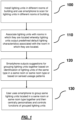
- a user may conveniently use the smartphone (300) to selectably associate each of the lighting units with the various rooms (500,600,700) of the building in which they are located such that each lighting unit (200) is configured to automatically output predefined default lighting characteristics corresponding to each of the rooms (500,600,700) or types of rooms in the building in which they are located.
- the smartphone (300) is also configured to output suggestions instructing the user when it is optimal to group certain lighting units (200) together based on best practices - for instance when two or more lighting units (200) of the same type have been associated by the user with the same room (500,600,700) or same type of room.
- the system also allows a user to use the smartphone (300) to manually define groups of lighting units (200) of the same type located in the same room or same type of room.
- the predefined default lighting characteristics settings for the lighting units (200) associated with the various rooms or types of rooms in the building, and, the suggestions for grouping the lighting units together, are predefined based upon an established set of best practices and common patterns of configuration and organisation of the various types of lighting units based on their location in the rooms of the building so as to assist in maximising the functional potential of all lighting units whilst minimising the need to tediously configure settings of each individual lighting unit.
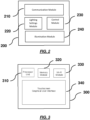
- each of the lighting units (200) includes an illumination module (240) for outputting lighting characteristics therefrom, a lighting settings module (220) for storing predefined lighting settings indicative of default lighting characteristics for output by the illumination module (240) depending upon the room or type of room in which the lighting unit (200) is located, and a communication module (210) for wireless communication with external devices such as the smartphone (300).
- the lighting units (200) each also include a control module (230) which is configured such that, in response to the user associating the lighting unit (200) with a room or type of room in which the lighting unit is located, the control module (230) will operate the illumination module (240) by reference to the lighting settings module (220) to output the predefined default lighting characteristic associated with the room or type of room in which it is located.
- Each of the lighting units (200) may also contain an identifier stored in the lighting settings module (220) that is readable by the smartphone (300) so as to identity each of the scanned lighting units (200) including the type, make and model of each lighting unit (200).
- the smartphone (300) includes a processor unit (310) operably connected with a memory module (320), a touchscreen display (340), and a communication module (330) via which the smartphone (300) is able to communicate with external devices.
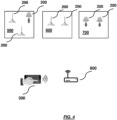
- the communications module (330) includes a WI-FI sub-module configured for communication via a WI-FI router (800) with WI-FI transceivers in each of the lighting units (200).
- a software application is downloadable into the memory module (320) of the smartphone (300) from an online server via the Internet or any other communication network and is executable by the processor unit (310) of the smartphone (300) to provide the graphical user-interface (340) operable on the touchscreen display (340) via which a user may organise and configure the various settings of the lighting units.
- the graphical user interface (340) may display icons representing the different lightning units (200) in rooms (500,600,700) of the building that have been scanned by the communication module of the smartphone, the type/model of each lighting unit (200) that is sensed by the communication module (330), and a representation of different types of rooms which may typically be found in the building. With these basic representations displayed on the graphical user interface (340) the user is able to effect associations between various lighting units and the rooms or room types in which they are located, and to group the various lighting units together, when appropriate to do so.
- Fig. 4 shows various rooms comprising a bedroom (500) a kitchen (600) and a living room (700) in a household building with each room containing different types of lighting units.
- the lighting units in each room (500,600,700) will output different lighting characteristics depending upon the room that they are in and also depending upon the type of lighting unit involved.
- the lighting characteristics are based on default lighting characteristics that are predefined in accordance with an established set of best practices and common configurations/settings.
- each icon which represents a unique name or identifier for each lighting unit (which may for instance be analogous to a MAC address of the lighting unit that is programmed into the lighting settings module of each lighting unit).
- the software application will also allow the user to create room icons on the graphical user interface (340) that represent the actual rooms (500,600,700) of the household. Once the room icons are created, the user is thus able to associate lighting icons representing actual lighting units with the room icons to create associations between them.
- the user may commence configuring each of the lighting units (200) in the various rooms (500,600,700) of the household by moving from one room to another in turn and setting up the lighting units (200) in each room to associate the lighting units (200) with the room in which they are located.
- the user in this example may arbitrarily commence the setup by firstly visiting the bedroom (500) and then selecting the room type template "bedroom" from the interactive-menu on the graphical user interface (340) to generate a bedroom icon on the graphical user interface (340).
- a new room icon will be created on the graphical user interface (340) representing the bedroom in which the user is currently located.
- the icon will be labelled simply as "bedroom” however if there are multiple bedroom icons generated which represent multiple bedrooms in the household, the graphical user interface will be configured with a customisation function to allow the user to customise the labelling for each bedroom icon that is created so as to allow each bedroom to be distinguishable.
- a room icon has been generated on the graphical user interface (340) of the smartphone (300) to define an actual room of the household, it will remain usable for future configurations and changes of settings as required by the user.
- the user will identify via the graphical user interface (340) the lighting icons representing each of the actual lighting units (200) located in the bedroom (500) in order to then selectably associate these lighting units with the bedroom (500).
- the lighting icons representing each of the actual lighting units (200) located in the bedroom (500) in order to then selectably associate these lighting units with the bedroom (500).
- the user may for instance be able to identify the icons for these lighting units as they may be labelled with a unique text identifier under the icons which may also be displayed on the physical lighting unit itself.
- the user will in turn create an association between each of the three lighting units and the bedroom (500) by for instance dragging the icons representing each of the three lighting units into contact with the bedroom icon on the graphical user interface (340).
- the graphical user interface is programmed to sense this interaction of the icons and interpret this interaction as effecting an association between the actual lighting units and the actual bedroom represented by the icons.
- the software application running on the smartphone (300) will store within the local memory store (320) a record of this and all other associations that are made between lighting units and rooms in the household so that the graphical user interface (340) will reflect the current status of all associations at any given time when the user is using the smartphone (300) to configure lighting units (200).
- the smartphone (300) Upon making the association between the three lighting units and the bedroom, the smartphone (300) is also configured to communicate, via the WI-FI network, association data that is indicative of the association of each of the three lighting units with the actual bedroom (500) whereupon the association data is stored in the lighting settings modules of the respective lighting units.
- the association data may simply indicate to the respective lighting units that the type of room in which with which they are currently associated is a bedroom, and, if there are multiple bedrooms defined, an identifier identifying the particular bedroom with which the lighting units are associated so that the lighting unit may distinguish which particular bedroom it is located in.
- the control module will read the association data stored in the lighting settings module and based on this information will now recognise that the lighting units are located in and associated with the bedroom of the building.
- the control module of each lighting unit will then automatically operate the respective illumination modules of each lighting unit to output predefined default lighting characteristics (as stored in the lighting settings module) which are suited for operation of the respective lighting units in a bedroom type room setting by reference to the lighting settings module indicating the association of the lighting units with the bedroom.
- predefined default lighting characteristics that will be output by these different types of lighting units will generally be quite different in the context of a bedroom setting or any other given room setting.
- one type of lighting unit that is installed in one type of room may be used in accordance with a very different useage pattern when the same lighting unit is installed in a different type of room (for instance a garage).
- Embodiments of the present invention recognise and reflect this by automatically providing predefined default lighting characteristics for different types of lighting units when installed in different types of rooms based on established best practices so that the functional potential of each lighting unit may be maximised.
- certain existing lighting systems tend to configure all lighting units to operate in exactly the same way irrespective of the type of lighting involved and irrespective of the room in which the lighting unit is located and the functional potential and ability to personalise the output of each lighting unit for optimal performance is compromised.
- the user will repeat the above steps for each of the remaining rooms in the household so as to associate all lighting units in each room with the respective rooms. If a user wishes to move a lighting unit from one room to another, for instance, if one of the table lamps is moved from the bedroom (500) to the kitchen (600), after installing the table lamp in the kitchen (600), the user will via the graphical user interface (340) of the smartphone (300) create a new association between the newly moved table lamp and the kitchen (600) in the manner described above. The control module of the table lamp will now control the output of the table lamp to output a different lighting characteristic to when the table lamp was previously installed in the bedroom (500).
- the lighting settings for the table lamp may be quickly and easily configured again so as to be suitable for bedroom (500) in which it is again located by simply creating the association between the table lamp with the bedroom (500) via the smartphone application.
- this obviates the need for technically unskilled home users to have to perform complex and tedious configurations of the multiple lighting units to configure them to operate optimally.
- the present invention there may be a variety of different templates for different room type that may be selectable in the user-interactive menu of the graphical user interface (340) for each different type of room (500,600,700).
- the availability of different templates for any given room type may be useful because for example different bedrooms in a household may typically be very different in nature and therefore be suited to different lighting characteristics from the same type of lighting device. For instance, two different bedrooms may vary in terms of size, configuration, ambient lighting, furnishings and décor, and the occupants of the different bedrooms may necessitate different lighting characteristics being output by any given lighting unit.
- predefined default lighting characteristics for each type of room, but there may also be different predefined default lighting characteristics for different rooms of the same type.
- These templates may be customisable by a user via the graphical user interface and they may also be shared amongst different users via an on-line database or web site providing access to different user created templates for instance.
- the smartphone (300) is also configured to automatically recognise when similar lighting units (200) that are located in a common room or common room type within the building and to automatically output an instructional message to the user via the graphical user interface suggesting the grouping of the similar lighting units together.
- the smartphone will recognise that these lighting units are of the same make and model and located in the same room and will then display a text message upon the graphical user interface instructing the user to group the table lamps together.
- the grouping operation may be effected by any means but for simplicity may involve simply dragging and dropping icons representing each of the table lamps on to another graphical icon representing the group.
- the smartphone Upon defining the grouping between the table lamps via the graphical user interface, the smartphone is configured to wirelessly communicate data indicative of the grouping to each of the table lamps so that when any one of the table lamps in the group are controlled (for instance by a remote control or a light switch), the other table lamp may follow the same operation. This may involve each of the table lamps relaying operational commands to the other table lamp so that they all follow the same operation.
- any further customisation and controlling of functionality of the table lamps may now be performed centrally on a group basis via the graphical user interface, so as to avoid unnecessary duplication of time and effort required in having to repeatedly configure and control multiple lighting units of the same type.
- the useage patterns of multiple lighting units installed within a premises may be monitored and analysed, with information resulting from the analysis then being useable to automatically control operations of the lighting units mimicking the useage behavior of the user.
- this useage pattern is able to be detected whereby both of these lighting units may then be configured to switch on and off at the same time automatically without the user necessarily switching on or off both lighting units.
- Embodiments may provide even more advanced functionality by detecting the time at which the multiple lighting units are switched on or off at the same time and then configuring the relevant lighting units to automatically switch on or off at a given time at which they would normally be switched on or off by the user.
- Other useage patterns that may be detected and copied automatically by groups of lighting units may include for instance the time of day at which certain lighting units are switched on or off, or, the order in which certain groups of lighting units are switched on or off.
- a central control unit may be communicatively connected with all lighting units in the household via the WI-FI network. Whenever any of the lighting units performs a function such as being switched on or switched off, the functions and timing of the functions may be detected by the central control unit via the WI-FI network. Thus for instance, when one lighting unit is switched on within a relatively short time to another lighting unit being switched on, then those two lighting units may be recorded as a potential match by then central control unit with a rank of 1. Subsequently, every time these same two lighting units are switched on, or switched off, or modified in a same way, within a relatively short time (e.g.
- the rank of 1 may be incremented to further indicate that the useage pattern of the two lighting devices are connected.
- the central control unit may be configured to automatically configure the two lighting units to automatically copy each other's behavior without requiring user operation of both lighting units in future.
- the predefined settings indicative of default lighting characteristics for output by illumination modules of the lighting units may be automatically updated periodically.
- an online database may store the predefined settings which may be centrally updated from time to time.
- Each of the lighting units may be communicably connected with the online database via an Internet connection and may be configured to automatically download updated settings periodically from the database into the settings modules of the lighting units.
- the online database may also include a front-end web interface via which users may upload and share their own user-created settings in respect of different types of lighting units and for different types of rooms which may be browsed and selectably downloaded by other users.
Landscapes
- Engineering & Computer Science (AREA)
- General Engineering & Computer Science (AREA)
- Theoretical Computer Science (AREA)
- Automation & Control Theory (AREA)
- Computer Networks & Wireless Communication (AREA)
- Human Computer Interaction (AREA)
- Physics & Mathematics (AREA)
- General Physics & Mathematics (AREA)
- Signal Processing (AREA)
- Circuit Arrangement For Electric Light Sources In General (AREA)
Claims (4)
- Système servant à commander une pluralité d'unités d'éclairage (200) qui sont situées dans des pièces d'un bâtiment, ledit système comprenant ladite pluralité d'unités d'éclairage (200) et une unité d'entrée utilisateur (300) par l'intermédiaire de laquelle un utilisateur peut associer de manière sélectionnable au moins l'une parmi la pluralité d'unités d'éclairage (200) avec un type de pièce dans lequel elle doit être située ;dans lequel ladite unité d'entrée utilisateur (300) comprend un module de communication sans fil (330) configuré pour communiquer sans fil des données d'association indiquant l'association de l'au moins une parmi la pluralité d'unités d'éclairage (200) avec le type de pièce dans lequel elle doit être située ; etdans lequel chacune de ladite pluralité d'unités d'éclairage (200) comporte de manière intégrée :un module de communication sans fil (210) configuré pour recevoir sans fil les données d'association à partir de l'unité d'entrée utilisateur (300) ;un module d'éclairement (240) par l'intermédiaire duquel une caractéristique d'éclairage peut être produite ;un module de paramètres d'éclairage (220) configuré pour stocker des paramètres prédéfinis de caractéristiques d'éclairage par défaut qui sont associées à chaque type de pièce, pour être produites par le module d'éclairement (220) ;dans lequel, pour chaque type de pièce, la caractéristique d'éclairage par défaut prédéfinie est différente ;un module de commande (230) moyennant quoi, en réponse aux données d'association reçues par l'intermédiaire du module de communication (240) de l'unité d'éclairage (200), le module de commande (230) est configuré pour faire fonctionner le module d'éclairement (240) de l'unité d'éclairage (230) de manière à produire la caractéristique d'éclairage par défaut associée avec le type de pièce auquel l'unité d'éclairage (200) est associée, en référence aux paramètres prédéfinis stockés dans le module de paramètres d'éclairage (220), le système étant caractérisé en ce que :le système comprend une base de données en ligne stockant les paramètres prédéfinis des caractéristiques d'éclairage par défaut,dans lequel les paramètres prédéfinis des caractéristiques d'éclairage par défaut sont automatiquement mis à jour périodiquement,dans lequel chaque unité d'éclairage est connectée de manière communicante à la base de données en ligne par l'intermédiaire d'une connexion Internet et configurée pour télécharger automatiquement et périodiquement des paramètres mis à jour depuis la base de données en ligne dans le module de paramètres d'éclairage respectif.
- Système selon l'une quelconque des revendications précédentes, dans lequel le type de pièce est une salle à manger, une cuisine, une salle de bains, une chambre, un salon, un couloir, un bureau, un garage.
- Système selon l'une quelconque des revendications précédentes, dans lequel les caractéristiques d'éclairage par défaut correspondant à chaque type de pièce sont définies par au moins l'une parmi :i. une caractéristique de couleur ;ii. une caractéristique de luminosité ;iii. une température de couleur de lumière blanche ; etiv. une caractéristique de temporisation pour la production d'au moins l'une parmi (i) à (iii).
- Système selon l'une quelconque des revendications précédentes, dans lequel l'unité d'entrée utilisateur (300) comporte au moins l'un parmi un téléphone mobile, une tablette, et un ordinateur.
Applications Claiming Priority (1)
| Application Number | Priority Date | Filing Date | Title |
|---|---|---|---|
| PCT/CN2016/076144 WO2017152418A1 (fr) | 2016-03-11 | 2016-03-11 | Système et procédé d'exploitation de multiples unités d'éclairage dans un bâtiment |
Publications (3)
| Publication Number | Publication Date |
|---|---|
| EP3238509A1 EP3238509A1 (fr) | 2017-11-01 |
| EP3238509A4 EP3238509A4 (fr) | 2018-08-15 |
| EP3238509B1 true EP3238509B1 (fr) | 2025-02-26 |
Family
ID=59790041
Family Applications (1)
| Application Number | Title | Priority Date | Filing Date |
|---|---|---|---|
| EP16845322.3A Active EP3238509B1 (fr) | 2016-03-11 | 2016-03-11 | Système d'exploitation de multiples unités d'éclairage dans un bâtiment |
Country Status (6)
| Country | Link |
|---|---|
| US (1) | US10959315B2 (fr) |
| EP (1) | EP3238509B1 (fr) |
| CN (1) | CN109196955B (fr) |
| AU (1) | AU2016396881A1 (fr) |
| MX (1) | MX2018010810A (fr) |
| WO (1) | WO2017152418A1 (fr) |
Families Citing this family (3)
| Publication number | Priority date | Publication date | Assignee | Title |
|---|---|---|---|---|
| US11337289B2 (en) * | 2017-08-23 | 2022-05-17 | Signify Holding B.V. | System and method for controlling output of a dynamic lighting scene by a group of lighting units |
| CN112703823B (zh) * | 2020-03-26 | 2023-10-10 | 松下知识产权经营株式会社 | 照明装置的快速调试 |
| CN117042248B (zh) * | 2023-07-12 | 2024-05-07 | 昆山恩都照明有限公司 | 一种自适应led灯具控制系统及方法 |
Family Cites Families (27)
| Publication number | Priority date | Publication date | Assignee | Title |
|---|---|---|---|---|
| US7047092B2 (en) | 2003-04-08 | 2006-05-16 | Coraccess Systems | Home automation contextual user interface |
| JP4374471B2 (ja) * | 2003-08-04 | 2009-12-02 | 学校法人同志社 | 照明制御システムおよび制御システム |
| US20060028212A1 (en) * | 2004-08-06 | 2006-02-09 | Steiner J P | System and method for graphically grouping electrical devices |
| US7498952B2 (en) * | 2005-06-06 | 2009-03-03 | Lutron Electronics Co., Inc. | Remote control lighting control system |
| US8994276B2 (en) * | 2006-03-28 | 2015-03-31 | Wireless Environment, Llc | Grid shifting system for a lighting circuit |
| US7680745B2 (en) * | 2007-01-29 | 2010-03-16 | 4Homemedia, Inc. | Automatic configuration and control of devices using metadata |
| CN101282605B (zh) | 2008-03-21 | 2011-12-07 | 浙江大学城市学院 | 基于ZigBee传感网的节能型室内照明无线智能控制系统及控制方法 |
| US8364325B2 (en) * | 2008-06-02 | 2013-01-29 | Adura Technologies, Inc. | Intelligence in distributed lighting control devices |
| US20100114340A1 (en) * | 2008-06-02 | 2010-05-06 | Charles Huizenga | Automatic provisioning of wireless control systems |
| US8053994B2 (en) * | 2009-06-03 | 2011-11-08 | Liu yuan-sheng | Intelligent wall switch |
| CN102004469B (zh) * | 2009-09-01 | 2012-06-27 | 王俊锋 | 一种酒店控制系统 |
| CN203057588U (zh) | 2012-02-13 | 2013-07-10 | 皇家飞利浦电子股份有限公司 | 光源的远程控制 |
| US8368310B1 (en) * | 2012-03-23 | 2013-02-05 | Inncom International, Inc. | System and method for distributed lighting device control |
| EP2685793B1 (fr) * | 2012-07-12 | 2019-09-04 | LG Innotek Co., Ltd. | Système et procédé de commande d'éclairage |
| JP2014056670A (ja) * | 2012-09-11 | 2014-03-27 | Panasonic Corp | 照明制御システム |
| JP6097963B2 (ja) * | 2012-09-13 | 2017-03-22 | パナソニックIpマネジメント株式会社 | 照明システム |
| TWI495395B (zh) * | 2013-03-11 | 2015-08-01 | 聚眾聯合科技股份有限公司 | 控制燈具之方法及其電腦程式產品 |
| TWI508627B (zh) * | 2013-03-22 | 2015-11-11 | 動聯國際股份有限公司 | 照明控制系統 |
| EP2890223B1 (fr) * | 2013-12-27 | 2020-05-27 | Panasonic Intellectual Property Corporation of America | Procédé et programme de commande de terminal mobile |
| KR20150101140A (ko) * | 2014-02-26 | 2015-09-03 | 한국전자통신연구원 | 지그비 무선 조명 제어 방법 및 그 장치 |
| TWI523578B (zh) | 2014-04-25 | 2016-02-21 | Cincon Electronics Co Ltd | A system and method for grouping a fixture on a DALI system using a handheld device |
| TWI511616B (zh) * | 2014-05-13 | 2015-12-01 | 索玉昇 | 以同步於ac電源頻率為基礎的調控系統與調控方法 |
| EP2950618B1 (fr) * | 2014-05-26 | 2018-10-10 | Harman Professional Denmark ApS | Système de commande de couleur avec étalonnage variable |
| JP6361967B2 (ja) * | 2014-07-29 | 2018-07-25 | パナソニックIpマネジメント株式会社 | 照明制御システム、制御装置、及び、照明制御方法 |
| CN204652728U (zh) * | 2015-04-23 | 2015-09-16 | 浙江警安科技有限公司 | 智能照明控制系统 |
| CN104837281B (zh) | 2015-05-27 | 2018-07-10 | 常州市武进区半导体照明应用技术研究院 | 照明控制系统、方法及装置 |
| US10893587B2 (en) * | 2016-09-23 | 2021-01-12 | Feit Electric Company, Inc. | Light emitting diode (LED) lighting device or lamp with configurable light qualities |
-
2016
- 2016-03-11 EP EP16845322.3A patent/EP3238509B1/fr active Active
- 2016-03-11 US US15/514,770 patent/US10959315B2/en active Active
- 2016-03-11 MX MX2018010810A patent/MX2018010810A/es unknown
- 2016-03-11 WO PCT/CN2016/076144 patent/WO2017152418A1/fr not_active Ceased
- 2016-03-11 CN CN201680085452.1A patent/CN109196955B/zh active Active
- 2016-03-11 AU AU2016396881A patent/AU2016396881A1/en not_active Abandoned
Also Published As
| Publication number | Publication date |
|---|---|
| WO2017152418A1 (fr) | 2017-09-14 |
| US20180368238A1 (en) | 2018-12-20 |
| CN109196955A (zh) | 2019-01-11 |
| US10959315B2 (en) | 2021-03-23 |
| MX2018010810A (es) | 2019-02-07 |
| CN109196955B (zh) | 2021-07-09 |
| EP3238509A4 (fr) | 2018-08-15 |
| AU2016396881A1 (en) | 2018-10-25 |
| EP3238509A1 (fr) | 2017-11-01 |
Similar Documents
| Publication | Publication Date | Title |
|---|---|---|
| KR102288777B1 (ko) | 조명 제어 장치 및 이의 조명 제어 방법 | |
| US20230345606A1 (en) | Configuring a load control system | |
| US11422521B2 (en) | Configuring a load control system | |
| CN113170565B (zh) | 负载控制系统、用于控制电气负载的方法和计算装置 | |
| US9437060B2 (en) | Initiating remote control using near field communications | |
| US20250165129A1 (en) | Configuring a load control system | |
| US20140359524A1 (en) | Method for controlling information apparatus and computer-readable recording medium | |
| US20160330819A1 (en) | Multiple light fixture commissioning systems and methods | |
| CN105490898A (zh) | 配置网络中装置的设备和方法 | |
| US10285247B2 (en) | Control installation for a lighting system and method for configuring and putting into service said control installation | |
| JP2018524777A (ja) | 照明システム内の装置を設定するための方法 | |
| EP3238509B1 (fr) | Système d'exploitation de multiples unités d'éclairage dans un bâtiment | |
| CN108803371A (zh) | 一种电器设备的控制方法以及装置 | |
| EP4008165A1 (fr) | Système de mise en service sans fil pour dispositifs dali | |
| EP3379904B1 (fr) | Configuration de systèmes d'éclairage | |
| JP2017212514A (ja) | 通信システム、通信装置、識別情報の設定方法、及びプログラム | |
| HK40117874A (zh) | 与负载控制系统通信并控制负载控制系统 | |
| HK40055080B (zh) | 与负载控制系统通信并控制负载控制系统 | |
| KR20180052209A (ko) | 조명 제어 데이터 생성 장치 및 방법 |
Legal Events
| Date | Code | Title | Description |
|---|---|---|---|
| STAA | Information on the status of an ep patent application or granted ep patent |
Free format text: STATUS: UNKNOWN |
|
| STAA | Information on the status of an ep patent application or granted ep patent |
Free format text: STATUS: THE INTERNATIONAL PUBLICATION HAS BEEN MADE |
|
| PUAI | Public reference made under article 153(3) epc to a published international application that has entered the european phase |
Free format text: ORIGINAL CODE: 0009012 |
|
| STAA | Information on the status of an ep patent application or granted ep patent |
Free format text: STATUS: REQUEST FOR EXAMINATION WAS MADE |
|
| 17P | Request for examination filed |
Effective date: 20170321 |
|
| AK | Designated contracting states |
Kind code of ref document: A1 Designated state(s): AL AT BE BG CH CY CZ DE DK EE ES FI FR GB GR HR HU IE IS IT LI LT LU LV MC MK MT NL NO PL PT RO RS SE SI SK SM TR |
|
| AX | Request for extension of the european patent |
Extension state: BA ME |
|
| R17P | Request for examination filed (corrected) |
Effective date: 20170321 |
|
| A4 | Supplementary search report drawn up and despatched |
Effective date: 20180718 |
|
| RIC1 | Information provided on ipc code assigned before grant |
Ipc: G06F 3/00 20060101ALI20180712BHEP Ipc: H05B 37/02 20060101AFI20180712BHEP Ipc: G06F 15/18 20060101ALI20180712BHEP Ipc: G06N 5/02 20060101ALI20180712BHEP |
|
| RAP1 | Party data changed (applicant data changed or rights of an application transferred) |
Owner name: WIZCONNECTED COMPANY LIMITED |
|
| DAV | Request for validation of the european patent (deleted) | ||
| DAX | Request for extension of the european patent (deleted) | ||
| RAP1 | Party data changed (applicant data changed or rights of an application transferred) |
Owner name: WIZ CONNECTED LIGHTING CO. LIMITED |
|
| STAA | Information on the status of an ep patent application or granted ep patent |
Free format text: STATUS: EXAMINATION IS IN PROGRESS |
|
| 17Q | First examination report despatched |
Effective date: 20210211 |
|
| RAP1 | Party data changed (applicant data changed or rights of an application transferred) |
Owner name: SIGNIFY HOLDING B.V. |
|
| REG | Reference to a national code |
Ref country code: DE Ref legal event code: R079 Free format text: PREVIOUS MAIN CLASS: H05B0037020000 Ipc: H05B0047190000 Ref document number: 602016091389 Country of ref document: DE |
|
| GRAP | Despatch of communication of intention to grant a patent |
Free format text: ORIGINAL CODE: EPIDOSNIGR1 |
|
| STAA | Information on the status of an ep patent application or granted ep patent |
Free format text: STATUS: GRANT OF PATENT IS INTENDED |
|
| RIC1 | Information provided on ipc code assigned before grant |
Ipc: H04L 12/28 20060101ALI20240905BHEP Ipc: H05B 47/19 20200101AFI20240905BHEP |
|
| INTG | Intention to grant announced |
Effective date: 20240916 |
|
| P01 | Opt-out of the competence of the unified patent court (upc) registered |
Free format text: CASE NUMBER: APP_60732/2024 Effective date: 20241112 |
|
| GRAS | Grant fee paid |
Free format text: ORIGINAL CODE: EPIDOSNIGR3 |
|
| GRAA | (expected) grant |
Free format text: ORIGINAL CODE: 0009210 |
|
| STAA | Information on the status of an ep patent application or granted ep patent |
Free format text: STATUS: THE PATENT HAS BEEN GRANTED |
|
| AK | Designated contracting states |
Kind code of ref document: B1 Designated state(s): AL AT BE BG CH CY CZ DE DK EE ES FI FR GB GR HR HU IE IS IT LI LT LU LV MC MK MT NL NO PL PT RO RS SE SI SK SM TR |
|
| REG | Reference to a national code |
Ref country code: GB Ref legal event code: FG4D |
|
| REG | Reference to a national code |
Ref country code: CH Ref legal event code: EP |
|
| REG | Reference to a national code |
Ref country code: DE Ref legal event code: R096 Ref document number: 602016091389 Country of ref document: DE |
|
| REG | Reference to a national code |
Ref country code: IE Ref legal event code: FG4D |
|
| REG | Reference to a national code |
Ref country code: NL Ref legal event code: MP Effective date: 20250226 |
|
| PG25 | Lapsed in a contracting state [announced via postgrant information from national office to epo] |
Ref country code: RS Free format text: LAPSE BECAUSE OF FAILURE TO SUBMIT A TRANSLATION OF THE DESCRIPTION OR TO PAY THE FEE WITHIN THE PRESCRIBED TIME-LIMIT Effective date: 20250526 |
|
| PG25 | Lapsed in a contracting state [announced via postgrant information from national office to epo] |
Ref country code: FI Free format text: LAPSE BECAUSE OF FAILURE TO SUBMIT A TRANSLATION OF THE DESCRIPTION OR TO PAY THE FEE WITHIN THE PRESCRIBED TIME-LIMIT Effective date: 20250226 |
|
| PG25 | Lapsed in a contracting state [announced via postgrant information from national office to epo] |
Ref country code: PL Free format text: LAPSE BECAUSE OF FAILURE TO SUBMIT A TRANSLATION OF THE DESCRIPTION OR TO PAY THE FEE WITHIN THE PRESCRIBED TIME-LIMIT Effective date: 20250226 |
|
| PGFP | Annual fee paid to national office [announced via postgrant information from national office to epo] |
Ref country code: DE Payment date: 20250528 Year of fee payment: 10 |
|
| PG25 | Lapsed in a contracting state [announced via postgrant information from national office to epo] |
Ref country code: ES Free format text: LAPSE BECAUSE OF FAILURE TO SUBMIT A TRANSLATION OF THE DESCRIPTION OR TO PAY THE FEE WITHIN THE PRESCRIBED TIME-LIMIT Effective date: 20250226 |
|
| REG | Reference to a national code |
Ref country code: LT Ref legal event code: MG9D |
|
| PG25 | Lapsed in a contracting state [announced via postgrant information from national office to epo] |
Ref country code: NO Free format text: LAPSE BECAUSE OF FAILURE TO SUBMIT A TRANSLATION OF THE DESCRIPTION OR TO PAY THE FEE WITHIN THE PRESCRIBED TIME-LIMIT Effective date: 20250526 Ref country code: IS Free format text: LAPSE BECAUSE OF FAILURE TO SUBMIT A TRANSLATION OF THE DESCRIPTION OR TO PAY THE FEE WITHIN THE PRESCRIBED TIME-LIMIT Effective date: 20250626 |
|
| PG25 | Lapsed in a contracting state [announced via postgrant information from national office to epo] |
Ref country code: NL Free format text: LAPSE BECAUSE OF FAILURE TO SUBMIT A TRANSLATION OF THE DESCRIPTION OR TO PAY THE FEE WITHIN THE PRESCRIBED TIME-LIMIT Effective date: 20250226 |
|
| PG25 | Lapsed in a contracting state [announced via postgrant information from national office to epo] |
Ref country code: HR Free format text: LAPSE BECAUSE OF FAILURE TO SUBMIT A TRANSLATION OF THE DESCRIPTION OR TO PAY THE FEE WITHIN THE PRESCRIBED TIME-LIMIT Effective date: 20250226 |
|
| PG25 | Lapsed in a contracting state [announced via postgrant information from national office to epo] |
Ref country code: LV Free format text: LAPSE BECAUSE OF FAILURE TO SUBMIT A TRANSLATION OF THE DESCRIPTION OR TO PAY THE FEE WITHIN THE PRESCRIBED TIME-LIMIT Effective date: 20250226 Ref country code: PT Free format text: LAPSE BECAUSE OF FAILURE TO SUBMIT A TRANSLATION OF THE DESCRIPTION OR TO PAY THE FEE WITHIN THE PRESCRIBED TIME-LIMIT Effective date: 20250626 |
|
| PG25 | Lapsed in a contracting state [announced via postgrant information from national office to epo] |
Ref country code: GR Free format text: LAPSE BECAUSE OF FAILURE TO SUBMIT A TRANSLATION OF THE DESCRIPTION OR TO PAY THE FEE WITHIN THE PRESCRIBED TIME-LIMIT Effective date: 20250527 Ref country code: BG Free format text: LAPSE BECAUSE OF FAILURE TO SUBMIT A TRANSLATION OF THE DESCRIPTION OR TO PAY THE FEE WITHIN THE PRESCRIBED TIME-LIMIT Effective date: 20250226 |
|
| REG | Reference to a national code |
Ref country code: AT Ref legal event code: MK05 Ref document number: 1771961 Country of ref document: AT Kind code of ref document: T Effective date: 20250226 |
|
| PG25 | Lapsed in a contracting state [announced via postgrant information from national office to epo] |
Ref country code: SE Free format text: LAPSE BECAUSE OF FAILURE TO SUBMIT A TRANSLATION OF THE DESCRIPTION OR TO PAY THE FEE WITHIN THE PRESCRIBED TIME-LIMIT Effective date: 20250226 |
|
| PG25 | Lapsed in a contracting state [announced via postgrant information from national office to epo] |
Ref country code: SM Free format text: LAPSE BECAUSE OF FAILURE TO SUBMIT A TRANSLATION OF THE DESCRIPTION OR TO PAY THE FEE WITHIN THE PRESCRIBED TIME-LIMIT Effective date: 20250226 |
|
| PG25 | Lapsed in a contracting state [announced via postgrant information from national office to epo] |
Ref country code: DK Free format text: LAPSE BECAUSE OF FAILURE TO SUBMIT A TRANSLATION OF THE DESCRIPTION OR TO PAY THE FEE WITHIN THE PRESCRIBED TIME-LIMIT Effective date: 20250226 |
|
| PG25 | Lapsed in a contracting state [announced via postgrant information from national office to epo] |
Ref country code: IT Free format text: LAPSE BECAUSE OF FAILURE TO SUBMIT A TRANSLATION OF THE DESCRIPTION OR TO PAY THE FEE WITHIN THE PRESCRIBED TIME-LIMIT Effective date: 20250226 |
|
| PG25 | Lapsed in a contracting state [announced via postgrant information from national office to epo] |
Ref country code: AT Free format text: LAPSE BECAUSE OF FAILURE TO SUBMIT A TRANSLATION OF THE DESCRIPTION OR TO PAY THE FEE WITHIN THE PRESCRIBED TIME-LIMIT Effective date: 20250226 |
|
| PG25 | Lapsed in a contracting state [announced via postgrant information from national office to epo] |
Ref country code: EE Free format text: LAPSE BECAUSE OF FAILURE TO SUBMIT A TRANSLATION OF THE DESCRIPTION OR TO PAY THE FEE WITHIN THE PRESCRIBED TIME-LIMIT Effective date: 20250226 Ref country code: CZ Free format text: LAPSE BECAUSE OF FAILURE TO SUBMIT A TRANSLATION OF THE DESCRIPTION OR TO PAY THE FEE WITHIN THE PRESCRIBED TIME-LIMIT Effective date: 20250226 |
|
| REG | Reference to a national code |
Ref country code: CH Ref legal event code: H13 Free format text: ST27 STATUS EVENT CODE: U-0-0-H10-H13 (AS PROVIDED BY THE NATIONAL OFFICE) Effective date: 20251023 |
|
| PG25 | Lapsed in a contracting state [announced via postgrant information from national office to epo] |
Ref country code: RO Free format text: LAPSE BECAUSE OF FAILURE TO SUBMIT A TRANSLATION OF THE DESCRIPTION OR TO PAY THE FEE WITHIN THE PRESCRIBED TIME-LIMIT Effective date: 20250226 |
|
| PG25 | Lapsed in a contracting state [announced via postgrant information from national office to epo] |
Ref country code: SK Free format text: LAPSE BECAUSE OF FAILURE TO SUBMIT A TRANSLATION OF THE DESCRIPTION OR TO PAY THE FEE WITHIN THE PRESCRIBED TIME-LIMIT Effective date: 20250226 |
|
| PG25 | Lapsed in a contracting state [announced via postgrant information from national office to epo] |
Ref country code: LU Free format text: LAPSE BECAUSE OF NON-PAYMENT OF DUE FEES Effective date: 20250311 |
|
| REG | Reference to a national code |
Ref country code: DE Ref legal event code: R097 Ref document number: 602016091389 Country of ref document: DE |
|
| REG | Reference to a national code |
Ref country code: BE Ref legal event code: MM Effective date: 20250331 |
|
| PG25 | Lapsed in a contracting state [announced via postgrant information from national office to epo] |
Ref country code: MC Free format text: LAPSE BECAUSE OF FAILURE TO SUBMIT A TRANSLATION OF THE DESCRIPTION OR TO PAY THE FEE WITHIN THE PRESCRIBED TIME-LIMIT Effective date: 20250226 |
|
| PLBE | No opposition filed within time limit |
Free format text: ORIGINAL CODE: 0009261 |
|
| STAA | Information on the status of an ep patent application or granted ep patent |
Free format text: STATUS: NO OPPOSITION FILED WITHIN TIME LIMIT |
|
| PG25 | Lapsed in a contracting state [announced via postgrant information from national office to epo] |
Ref country code: BE Free format text: LAPSE BECAUSE OF NON-PAYMENT OF DUE FEES Effective date: 20250331 |
|
| PG25 | Lapsed in a contracting state [announced via postgrant information from national office to epo] |
Ref country code: CH Free format text: LAPSE BECAUSE OF NON-PAYMENT OF DUE FEES Effective date: 20250331 |
|
| PG25 | Lapsed in a contracting state [announced via postgrant information from national office to epo] |
Ref country code: IE Free format text: LAPSE BECAUSE OF NON-PAYMENT OF DUE FEES Effective date: 20250311 |
|
| 26N | No opposition filed |
Effective date: 20251127 |
|
| PGFP | Annual fee paid to national office [announced via postgrant information from national office to epo] |
Ref country code: GB Payment date: 20260319 Year of fee payment: 11 |
|
| PGFP | Annual fee paid to national office [announced via postgrant information from national office to epo] |
Ref country code: FR Payment date: 20260323 Year of fee payment: 11 |