EP3238558B1 - Schnalle für helm - Google Patents
Schnalle für helm Download PDFInfo
- Publication number
- EP3238558B1 EP3238558B1 EP16171960.4A EP16171960A EP3238558B1 EP 3238558 B1 EP3238558 B1 EP 3238558B1 EP 16171960 A EP16171960 A EP 16171960A EP 3238558 B1 EP3238558 B1 EP 3238558B1
- Authority
- EP
- European Patent Office
- Prior art keywords
- unit
- band
- toothed portion
- locking unit
- locking
- Prior art date
- Legal status (The legal status is an assumption and is not a legal conclusion. Google has not performed a legal analysis and makes no representation as to the accuracy of the status listed.)
- Active
Links
Images


Classifications
-
- A—HUMAN NECESSITIES
- A42—HEADWEAR
- A42B—HATS; HEAD COVERINGS
- A42B3/00—Helmets; Helmet covers ; Other protective head coverings
- A42B3/04—Parts, details or accessories of helmets
- A42B3/08—Chin straps or similar retention devices
-
- A—HUMAN NECESSITIES
- A44—HABERDASHERY; JEWELLERY
- A44B—BUTTONS, PINS, BUCKLES, SLIDE FASTENERS, OR THE LIKE
- A44B11/00—Buckles; Similar fasteners for interconnecting straps or the like, e.g. for safety belts
- A44B11/25—Buckles; Similar fasteners for interconnecting straps or the like, e.g. for safety belts with two or more separable parts
-
- A—HUMAN NECESSITIES
- A44—HABERDASHERY; JEWELLERY
- A44B—BUTTONS, PINS, BUCKLES, SLIDE FASTENERS, OR THE LIKE
- A44B11/00—Buckles; Similar fasteners for interconnecting straps or the like, e.g. for safety belts
- A44B11/006—Attachment of buckle to strap
-
- A—HUMAN NECESSITIES
- A44—HABERDASHERY; JEWELLERY
- A44D—INDEXING SCHEME RELATING TO BUTTONS, PINS, BUCKLES OR SLIDE FASTENERS, AND TO JEWELLERY, BRACELETS OR OTHER PERSONAL ADORNMENTS
- A44D2200/00—General types of fasteners
- A44D2200/10—Details of construction
Definitions
- the present invention relates to a buckle for a helmet.
- a buckle for a helmet is used with sports helmets including motorcycle helmets, ski helmets, and the like, and is a device employed for the fastening/unfastening, length-adjustment or the like of a band provided to the helmets.
- the buckle for the helmet needs to firmly fix the band fastened thereto and to enable the easy operation thereof upon the fastening/unfastening or length-adjustment of the band.
- the invention entitled “Buckle Device for Length Adjustment” is present in the prior art.
- This prior art discloses the configuration in which a lever 230 is used to fasten or unfasten a band strap 110 or to adjust the length of the band strap 110.
- the lever 230 is pulled in the direction opposite the direction in which the band strap 110 is introduced, the lever 230 is rotated along with a catcher 220 about a shaft, causing teeth 221 of the catcher 220 to be disengaged from gear-teeth 111 of the band strap 110. In this way, the fastening of the catcher 220 and the band strap 110 is released.
- the prior art relates to a pull type device for pulling the lever 230, the user may have difficulty in operation while riding a motorcycle or enjoying sports, such as skiing.
- EP 0 772 983 A1 discloses a locking device for chin-straps of safety helmets for motorcyclists comprising a base for taking a toothed chin-strap provided with a terminal for restraining the chin-strap, an oscillating ratchet provided at the bottom with engagement teeth and a "C"-shaped front profile and a cam-shaped oscillating control lever having a convex arched upper profile.
- the present invention has been made in view of the above problems, and it is an object of the present invention to provide a buckle for a helmet, which is of a push type in which a locking unit is pivotally rotated as a user pushes an operating unit, whereby the fastening of the locking unit and a band unit may be released.
- a buckle for a helmet including a band unit provided with a first toothed portion including one or more teeth and recesses, a base unit for guiding sliding of the band unit when the band unit is introduced or retracted, a locking unit pivotally rotatably fastened to one side of the base unit, the locking unit being provided on one surface thereof, which faces the band unit, with a second toothed portion including one or more teeth and recesses so as to correspond to the first toothed portion, the second toothed portion being pushed toward the band unit, and an operating unit fastened to an opposite side of the base unit so as to be linearly movable toward the locking unit, the operating unit serving to pivotally rotate the locking unit so that the second toothed portion is moved away from the band unit when it is moved toward the locking unit so as to apply a pressure to the locking unit.
- the locking unit is provided on one end thereof, which faces the operating unit, with a first slope, and on one end thereof, which faces the locking unit, with a second slope, and wherein, when the user pushes the operating unit as to linearly move toward the locking unit, the second slope may slide on the first slope to thereby push one surface of the locking unit, causing the locking unit to be pivotally rotated.
- a first recess among the teeth and recesses of the first toothed portion which meets the teeth and recesses of the second toothed portion firstly when the band unit is introduced into the base unit, may have a width that is smaller than a width of a first tooth among the teeth and recesses of the second toothed portion, which meets the teeth and recesses of the first toothed portion firstly when the band unit is introduced into the base unit, and may have a width that is the same as or greater width than a width of a second tooth among the teeth and recesses of the second toothed portion, which meets the teeth and recesses of the first toothed portion secondly when the band unit is introduced into the base unit.
- the buckle may further include an elastic member provided between the base unit and the locking unit for providing elastic force so as to allow the second toothed portion to be pushed toward the band unit.
- the elastic member may be a torsion spring, and one end of the torsion spring may be caught by an elastic support portion of the base unit, and a remaining end of the torsion spring is caught by the locking unit.
- the base unit may include a bottom wall extending in a plate shape so as to correspond to the band unit, and a pair of sidewalls extending from opposite sides of the bottom wall so as to face each other, the locking unit being pivotally rotatably fastened to one end of each sidewall, and the operating unit being movably fastened to a remaining end of the sidewall.
- the sidewall may have a first fastening hole formed in the one end thereof
- the locking unit may have a second fastening hole formed therein at a position corresponding to the first fastening hole, and a first fastening pin may be inserted through the first fastening hole and the second fastening hole.
- the sidewall may have a third fastening hole formed in the remaining end thereof
- the operating unit may have a fourth fastening hole formed therein at a position corresponding to the third fastening hole
- a second fastening pin may be inserted through the third fastening hole and the fourth fastening hole.
- the fourth fastening hole may have a width in a given direction that is greater than a diameter of the second fastening pin in order to allow the operating unit to be movable toward the locking unit relative to the base unit.
- the sidewall may have a guide groove formed in the remaining end thereof so as to be indented toward the locking unit, and the operating unit may have a guide protrusion inserted into the guide groove so as to move along the guide groove.
- the base unit may further include a guide member for extending from an end of the bottom wall to which the band unit is introduced, and the guide member may be tilted from the end of the bottom wall in a direction opposite a direction in which the sidewalls extend from the bottom wall.
- a buckle for a helmet in accordance with the embodiments of the present invention is used in sports helmets including motorcycle helmets, ski helmets, or the like, and is a device employed for the fastening/unfastening, length-adjustment or the like of a band provided in the helmets.
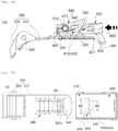
- FIG. 1 is a perspective view illustrating a buckle for a helmet in accordance with an embodiment of the present invention
- FIG. 2 is an exploded perspective view illustrating the buckle for the helmet in accordance with the embodiment of the present invention.
- the buckle for the helmet designated by reference numeral 100, in accordance with the embodiment of the present invention includes a band unit 300 provided with a first toothed portion 340 including one or more teeth and recesses, a base unit 400 for guiding the sliding of the band unit 300 when the band unit 300 is introduced or retracted, a locking unit 500 pivotally rotatably fastened to one side of the base unit 400, the locking unit 500 being provided on one surface thereof, which faces the band unit 300, with a second toothed portion 540 including one or more teeth and recesses so as to correspond to the first toothed portion 340, the second toothed portion 540 being adapted to be pushed toward the band unit 300, and an operating unit 600 fastened to the other side of the base unit 400 so as to be movable toward the locking unit 500, the operating unit 600 being configured to pivotally rotate the locking unit 500 so that the second toothed portion 540 is moved away from the band unit 300 when the operating unit 600 is moved toward the locking unit 500
- the band unit 300 may be fastened to the locking unit 500 and may be comprised of a main body 310, a mounting piece 320, and a third fastening pin 330, for example.
- the main body 310 may take the form of a curved plate so as to be introduced into or retracted from the base unit 400 under the guidance of the base unit 400, and may include, for example, an introduction portion 313, an extending portion 315, and a detent 317.
- the introduction portion 313 is located at one end of the main body 310, and thus is a portion that is initially introduced into the base unit 400.
- both corners of the introduction portion 313 may be rounded for the easy introduction of the band unit 300 to the base unit 400.
- the extending portion 315 extends from the introduction portion 313 to the detent 317, and is provided with the first toothed portion 340 on one surface (i.e. the upper surface) thereof, which faces the locking unit 500.
- the first toothed portion 340 includes one or more teeth and recesses. That is, the first toothed portion 340 includes teeth 343 and recesses 341, which are successively arranged in combination. At this time, the first toothed portion 340 may be engaged with the second toothed portion 540 of the locking unit 500.
- the detent 317 may obliquely extend from the extending portion 315 and may serve to limit the introduction of the band unit 300 to the base unit 400.
- the mounting piece 320 is configured so as to be connected to, for example, a band or a belt to thereby be mounted to a helmet.
- the mounting piece 320 may be pivotally rotatably fastened to the detent 317 of the main body 310 using the third fastening pin 330.
- the base unit 400 serves to guide the sliding of the band unit 300 when the band unit 300 is introduced or retracted and also serves to support the locking unit 500 and the operating unit 600.
- the base unit 400 may include a bottom wall 410 and sidewalls 420.
- the bottom wall 410 may extend to have a plate shape so as to correspond to the band unit 300
- the sidewalls 420 may extend in a pair from opposite sides (i.e. the longitudinal rims) of the bottom wall 410 so as to face each other.
- the locking unit 500 is pivotally rotatably fastened to one of the sidewalls 420 (located in the direction in which the band unit 300 is introduced), and the operating unit 600 is movably fastened to the other one of the sidewalls 420 (located in the direction opposite the direction in which the band unit 300 is introduced). More specifically, a first fastening hole 421 is formed in one end of each of the sidewalls 420, a second fastening hole 521 is formed in the locking unit 500 at the position corresponding to the first fastening hole 421, and a first fastening pin 423 is inserted through the first fastening hole 421 and the second fastening hole 521.
- the locking unit 500 may be pivotally rotatably fastened to one end of the respective sidewalls 420 using the first fastening pin 423, which is a rotation axis.
- a third fastening hole 425 is formed in the other end of each of the sidewalls 420
- a fourth fastening hole 625 is formed in the operating unit 600 at a position corresponding to the third fastening hole 425
- a second fastening pin 427 is inserted through the third fastening hole 425 and the fourth fastening hole 625.
- the diameter of the third fastening hole 425 may correspond to the diameter D of the second fastening pin 427, as illustrated in FIGS.
- the width W4 of the fourth fastening hole 625 in a given direction may be greater than the diameter of the second fastening pin 427.
- the operating unit 600 may be fastened to the other sidewall 420 so as to be linearly moved toward the locking unit 500 relative to the base unit 400.
- a guide groove 429 is formed in the other end of each of the sidewalls 420 (i.e.
- a guide protrusion 629 may be formed on the operating unit 600 so as to be inserted into and linearly moved along the guide groove 429.
- the operating unit 600 may be guided by the guide groove 429, in which the guide protrusion 429 is inserted, and by the second fastening pin 427, which is inserted in the fourth fastening hole 625, when the operating unit 600 is linearly moved toward the locking unit 500 relative to the base unit 400.
- the base unit 400 is connected to, for example, a band or a belt to thereby be mounted to a helmet.
- the base unit 400 may include a connection portion 430 for the connection of the band or the belt.
- the connection portion 430 may extend from the other end of each sidewall 420 (i.e. the end located in the direction opposite the direction in which the band unit 300 is introduced) so as to be away from (i.e. downward from) the operating unit 600.
- the base unit 400 may include the elastic support portion 440, by which one end of an elastic member 510 for providing the locking unit 500 with elastic force is caught.
- the elastic support portion 440 may extend so as to connect the ends of the sidewalls 420 (i.e. the ends located in the direction in which the band unit 300 is introduced) to each other.
- the locking unit 500 serves to fix the band unit 300 or to enable the introduction or retraction of the band unit 300.
- the locking unit 500 is pivotally rotatably fastened to one side of the base unit 400 using the first fastening pin 423.
- the locking unit 500 is disposed so as to be spaced apart from the bottom wall 410 of the base unit 400 (see FIG. 4A )
- the band unit 300 may be introduced or retracted through the space between the bottom wall 410 of the base unit 400 and the locking unit 500.
- the locking unit 500 is provided on the surface thereof, which faces the band unit 300 (i.e. the lower surface), with the second toothed portion 540, which corresponds to the first toothed portion 340 of the band unit 300.
- the second toothed portion 540 includes one or more teeth and recesses. That is, as illustrated in FIG. 2 , the second toothed portion 540 includes teeth 543 and recesses 541, which are successively arranged in combination.
- the elastic member 510 of the locking unit 500 applies elastic force to the band unit 300 via the first fastening pin 423, which is a rotation axis, the second toothed portion 540 of the locking unit 500 may be pushed toward the band unit 300, thereby being engaged with the first toothed portion 340 of the band unit 300.
- the teeth 543 of the second toothed portion 540 and the teeth 343 of the first toothed portion 340 may be inclined so as to correspond to each other.
- the locking unit 500 when the user attempts to introduce the band unit 300 into the band unit 400, the locking unit 500 is pivotally rotated by a prescribed angle about the first fastening pin 423, which is a rotation axis, so as to allow the band unit 300 to be moved into the base unit 400,
- the locking unit 500 cannot be pivotally rotated about the first fastening pin 423, and thus the first toothed portion 340 and the second toothed portion 540 remain fastened to each other, whereby the band unit 300 cannot be moved outward from the base unit 400.
- the band unit 300 may be moved outward from the base unit 400 when the band unit 300 is pivotally rotated using the operating unit 600 so as to release the fastening of the first toothed portion 340 and the second toothed portion 540. A detailed description related to this will follow.
- the elastic member 510 may be provided between the base unit 400 and the locking unit 500 to apply the elastic force required to push the second toothed portion 540 toward the band unit 300.
- the elastic member 510 may be a torsion spring, for example.
- the torsion spring 510 may be located in a recessed portion 530 (see FIG. 2 ), which is formed in the side surface of the locking unit 500 facing each sidewall 420, so that the first fastening pin 423 is inserted through the torsion spring 510.
- One end of the torsion spring 510 may be caught by the elastic support portion 440 of the base unit 400 and the other end of the torsion spring 510 may be caught by one end of the recessed portion 530 of the locking unit 500.
- the torsion spring 510 may provide elastic force to pivotally rotate the locking unit 500 so that the second toothed portion 540 is pushed toward the band unit 300.
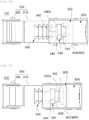
- FIGS. 5A to 5C are plan views illustrating the initial process of fastening the buckle for the helmet in accordance with the embodiment of the present invention.
- a first recess 342 among the teeth and recesses of the first toothed portion 340 which meets the teeth and recesses of the second toothed portion 540 firstly when the band unit 300 is introduced into the base unit 400, may have a smaller width W1 than the width W2 of a first tooth 544 among the teeth and recesses of the second toothed portion 540, which meets the teeth and recesses of the first toothed portion 340 firstly when the band unit 300 is introduced into the base unit 400 (W1 ⁇ W2).
- the first tooth 544 is not engaged with the first recess 342 (see FIG. 5B ), but the second tooth 545 is engaged with the first recess 342 (see FIG. 5C ).
- the band unit 300 and the locking unit 500 are fastened to each other using two recesses and two teeth (see FIG. 5C ), rather than using only one recess and one tooth (see FIG. 5B ), firm fastening between the band unit 300 and the locking unit 500 may be realized.
- W1 ⁇ W2 width of the first recess 342 that is smaller than the width of the first tooth 544
- W1>W3 a width of the first recess 342 that is greater than the
- bosses 342a may protrude from both width-direction ends of the first recess 342. At this time, the distance W1 between the bosses 342a may be smaller than the width W2 of the first tooth 544, or may be equal to or greater than the width W3 of the second tooth 545. It is to be noted that this configuration is given by way of example and that the scope of the present invention should not be limited to this configuration.
- the operating unit 600 serves to pivotally rotate the locking unit 500 so as to release the engagement of the first toothed portion 340 and the second toothed portion 540.
- the operating unit 600 is fastened to the other side of the base unit 400 via, for example, the second fastening pin 427 and the guide protrusion 629, so as to be linearly moved toward the locking unit 500.
- the band unit 300 may be introduced or retracted through the space between the bottom wall 410 of the base unit 400 and the operating unit 600.
- FIG. 1 serves to pivotally rotate the locking unit 500 so as to release the engagement of the first toothed portion 340 and the second toothed portion 540.
- the operating unit 600 is fastened to the other side of the base unit 400 via, for example, the second fastening pin 427 and the guide protrusion 629, so as to be linearly moved toward the locking unit 500.
- the band unit 300 may be introduced or retracted through the space between the bottom wall 410 of the base unit 400 and the operating unit 600.
- FIG. 1
- the second toothed portion 540 of the locking unit 500 may cause the locking unit 500 to be pivotally rotated away from the band unit 300.
- the operating unit 600 and the locking unit 500 may be disposed in substantially the same plane.
- a first slope 550 may be formed on one end of the locking unit 500 that faces the operating unit 600
- a second slope 650 may be formed on one end of the operating unit 600 that faces the locking unit 500 so as to correspond to the first slope 650.
- the first slope 550 of the locking unit 550 may face the bottom wall 410 of the base unit 400
- the second slope 650 of the operating unit 600 may face the direction opposite the bottom wall 410 of the base unit 400.
- the locking unit 500 When the locking unit 500 is pivotally rotated away from the band unit 300 as described above, the first toothed portion 340 of the band unit 300 is disengaged from the second toothed portion 540 of the locking unit 500, whereby the band unit 300 is freely movable.
- the locking unit 500 is pivotally rotated closer to the band unit 300 by the elastic force provided to the locking unit 500, whereby the first slope 550 of the locking unit 500 pushes the second slope 650 of the operating unit 600, allowing the operating unit 600 to be linearly moved in the direction opposite the locking unit 500.
- the locking unit 500 When the locking unit 500 is pivotally rotated closer to the band unit 300 as described above, the first toothed portion 340 of the band unit 300 and the second toothed portion 540 of the locking unit 500 are again engaged with each other, whereby the band unit 300 may be fixed.
- the helmet buckle 100 in accordance with the present embodiment may be of a push type so that the user simply releases the fastening of the locking unit 500 and the band unit 300 by applying a pressure to the operating unit 600, and therefore may advantageously allow the user who is riding a motorcycle or is enjoying skiing to easily operate the buckle 100.
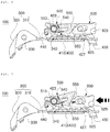
- FIGS. 6 to 10 are sectional views illustrating the operation of the buckle for the helmet in accordance with the embodiment of the present invention.
- the operation of the helmet buckle 100 in accordance with the embodiment of the present invention will now be described with reference to FIGS. 6 to 10 .
- FIGS. 6 to 8 illustrate the process of introducing the band unit 300 into the base unit 400.
- the introduction portion 313 of the band unit 300 passes through the space between the bottom wall 410 of the base unit 400 and the elastic support portion 440 to thereby be inserted into the space between the bottom wall 410 of the base unit 400 and the locking unit 500 and the space between the bottom wall 410 of the base unit 400 and the operating unit 600
- the second toothed portion 540 of the locking unit 500 is engaged with the first toothed portion 340 formed on the main body 310 of the band unit 300, thus causing the band unit 300 to be moved into the base unit 400.
- the locking unit 500 is pivotally rotated about the first fastening pin 423. More specifically, the locking unit 500 may be repeatedly pivotally rotated away from the band unit 300 (see FIG. 7 ) and may then be pivotally rotated toward the band unit 300 by the elastic force of the elastic member 510 (see FIG. 8 ) .
- FIGS. 9 and 10 illustrate the process of retracting the band unit 300 from the base unit 400.
- the operating unit 600 when the user pushes the operating unit 600 toward the locking unit 500, the operating unit 600 is linearly moved toward the locking unit 500, causing the second slope 650 of the operating unit 600 to slide on the first slope 550 of the locking unit 500 to thereby push one surface (i.e. the lower surface provided with the second toothed portion 540) of the locking unit 500, whereby the locking unit 500 may be pivotally rotated away from the band unit 300 about the first fastening pin 423.
- the fastening between the first toothed portion 340 of the band unit 300 and the second toothed portion 540 of the locking unit 500 may be released. Thereafter, as illustrated in FIG. 10 , when the band unit 300 is pulled, the band unit 300 may sequentially pass through the space between the bottom wall 410 of the base unit 400 and the operating unit 600 and the space between the bottom wall 410 of the base unit 400 and the locking unit 500, thereby being retracted through the space between the bottom wall 410 of the base unit 400 and the elastic support portion 440.
- FIG. 11 is a side view illustrating a buckle for a helmet in accordance with another embodiment of the present invention.
- a buckle for a helmet designated by reference numeral 200, in accordance with another embodiment of the present invention may include a guide member 700 provided on the base unit 400.
- the guide member 700 extends from one end of the bottom wall 410 of the base unit 400 to which the band unit 300 is introduced.
- the guide member 700 is tilted from the end of the bottom wall 410 in the direction (i.e. in the downward direction) opposite the direction (i.e. the upward direction) in which the sidewalls 420 extend from the bottom wall 410. That is, the guide member 700 may extend so as to be tilted downward from the end of the bottom wall 410.
- the guide member 700 may more easily introduce the band unit 300 into the base unit 400.
- the present invention may provide a push-type buckle for a helmet in which a locking unit is pivotally rotated when a user pushes an operating unit, whereby the fastening of the locking unit and a band unit may be released.
- a locking unit is pivotally rotated when a user pushes an operating unit, whereby the fastening of the locking unit and a band unit may be released.
Landscapes
- Buckles (AREA)
- Helmets And Other Head Coverings (AREA)
Claims (9)
- Eine Schnalle für einen Helm, umfassend:eine Bandeinheit (300), die mit einem ersten gezahnten Abschnitt (340) versehen ist, der einen oder mehrere Zähne und Aussparungen enthält;eine Basiseinheit (400) zum Führen des Gleitens der Bandeinheit (300), wenn die Bandeinheit (300) eingebracht oder zurückgezogen wird;eine Verriegelungseinheit (500), die schwenkbar drehbar an einer Seite der Basiseinheit (400) befestigt ist, wobei die Verriegelungseinheit (500) an einer Oberfläche davon vorgesehen ist, die der Bandeinheit (300) zugewandt ist, mit einem zweiten gezahnten Abschnitt, der einen oder mehrere Zähne und Aussparungen aufweist, um dem ersten gezahnten Abschnitt (340) zu entsprechen, wobei der zweite gezahnte Abschnitt (540) in Richtung der Bandeinheit (300) gedrückt wird; undeine Bedieneinheit (600), die an einer gegenüberliegenden Seite der Basiseinheit (400) befestigt ist, dadurch gekennzeichnet, dass die Bedieneinheit (600) linear in Richtung der Verriegelungseinheit (500) bewegbar ist, wobei die Bedieneinheit (600) dazu dient, die Verriegelungseinheit (500) zu drehen, so dass der zweite gezahnte Abschnitt (540) von der Bandeinheit (300) wegbewegt wird, wenn er in Richtung der Verriegelungseinheit (500) bewegt wird, um einen Druck auf die Verriegelungseinheit (500) auszuüben,wobei die Verriegelungseinheit (500) an einem Ende davon, das der Bedieneinheit (600) zugewandt ist, mit einer ersten Neigung (550) versehen ist,wobei die Bedieneinheit (600) an einem Ende davon, das der Verriegelungseinheit (500) zugewandt ist, mit einer zweiten Neigung (650) versehen ist, undwobei, wenn ein Benutzer die Bedieneinheit (600) drückt, um sich linear in Richtung der Verriegelungseinheit (500) zu bewegen, die zweite Neigung (650) auf der ersten Neigung (550) gleitet, um dadurch eine Oberfläche der Verriegelungseinheit (500) zu drücken, wodurch bewirkt wird, dass die Verriegelungseinheit (500) schwenkbar gedreht wird.
- Schnalle nach Anspruch 1, wobei eine erste Aussparung (342) zwischen den Zähnen und Aussparungen des ersten gezahnten Abschnitts (340), der zuerst auf die Zähne und Aussparungen des zweiten gezahnten Abschnitts (540) trifft, wenn die Bandeinheit (300) in die Basiseinheit (400) eingebracht wird, eine Breite aufweist, die kleiner ist als eine Breite eines ersten Zahns (544) zwischen den Zähnen und Aussparungen des zweiten gezahnten Abschnitts (540), der zuerst auf die Zähne und Aussparungen des ersten gezahnten Abschnitts (340) trifft, wenn die Bandeinheit (300) in die Basiseinheit (400) eingebracht wird, und eine Breite aufweist, die gleich oder größer als eine Breite eines zweiten Zahns (545) unter den Zähnen und Aussparungen des zweiten gezahnten Abschnitts (540) ist, der dann auf die Zähne und Aussparungen des ersten gezahnten Abschnitts (340) trifft, wenn die Bandeinheit (300) in die Basiseinheit (400) eingebracht wird.
- Schnalle nach Anspruch 1, die ferner ein elastisches Element (510) umfasst, das zwischen der Basiseinheit (400) und der Verriegelungseinheit (500) vorgesehen ist, um eine elastische Kraft bereitzustellen, um zu ermöglichen, dass der zweite gezahnte Abschnitt (540) in Richtung der Bandeinheit (300) gedrückt wird.
- Schnalle nach Anspruch 3, wobei das elastische Element (510) eine Torsionsfeder ist, und
wobei ein Ende der Torsionsfeder von einem elastischen Stützabschnitt (440) der Basiseinheit (400) erfasst wird, und ein verbleibendes Ende der Torsionsfeder von der Verriegelungseinheit (500) erfasst wird. - Schnalle nach Anspruch 1, wobei die Basiseinheit (400) Folgendes umfasst:eine Bodenwand (410), die sich in einer Plattenform erstreckt, um der Bandeinheit (300) zu entsprechen; undein Paar Seitenwände (420), die sich von gegenüberliegenden Seiten der Bodenwand (410) erstrecken, um einander zugewandt zu sein, wobei die Verriegelungseinheit (500) schwenkbar drehbar an einem Ende jeder Seitenwand (420) befestigt ist, und die Bedieneinheit (600) beweglich an einem verbleibenden Ende der Seitenwand (420) befestigt ist.
- Schnalle nach Anspruch 5, wobei die Seitenwand (420) ein erstes Befestigungsloch (421) aufweist, das in einem Ende davon ausgebildet ist, und die Verriegelungseinheit (500) ein zweites Befestigungsloch (521) aufweist, das in einer Position ausgebildet ist, die dem ersten Befestigungsloch (421) entspricht und ein erster Befestigungsstift (423) durch das erste Befestigungsloch (421) und das zweite Befestigungsloch (521) eingebracht ist.
- Schnalle nach Anspruch 5, wobei die Seitenwand (420) ein drittes Befestigungsloch (425) aufweist, das in ihrem verbleibenden Ende ausgebildet ist, und die Bedieneinheit (600) ein viertes Befestigungsloch (625) aufweist, das in einer Position ausgebildet ist, die dem dritten Befestigungsloch (425) entspricht, und ein zweiter Befestigungsstift (427) durch das dritte Befestigungsloch (425) und das vierte Befestigungsloch (625) eingebracht ist, und
wobei das vierte Befestigungsloch (625) in einer gegebenen Richtung eine Breite aufweist, die größer ist als ein Durchmesser des zweiten Befestigungsstifts (427), um zu ermöglichen, dass die Bedieneinheit (600) in Richtung der Verriegelungseinheit (500) relativ zur Basiseinheit (400) bewegbar ist. - Schnalle nach Anspruch 5, wobei die Seitenwand (420) eine Führungsnut (429) aufweist, die an ihrem verbleibenden Ende so ausgebildet ist, dass sie in Richtung der Verriegelungseinheit (500) eingekerbt ist wobei die Bedieneinheit (600) einen Führungsvorsprung (629) aufweist, der in die Führungsnut (429) eingesetzt ist, um sich entlang der Führungsnut (429) zu bewegen.
- Schnalle nach Anspruch 5, wobei die Basiseinheit (400) ferner ein Führungselement (700) umfasst, um sich von einem Ende der Bodenwand (410) zu erstrecken, in die die Bandeinheit (300) eingebracht ist, und wobei das Führungselement (700) vom Ende der Bodenwand (410) in eine Richtung geneigt ist, die einer Richtung entgegengesetzt ist, in der sich die Seitenwände (420) von der Bodenwand (410) erstrecken.
Applications Claiming Priority (1)
| Application Number | Priority Date | Filing Date | Title |
|---|---|---|---|
| KR1020160050651A KR101791655B1 (ko) | 2016-04-26 | 2016-04-26 | 헬멧용 버클 |
Publications (2)
| Publication Number | Publication Date |
|---|---|
| EP3238558A1 EP3238558A1 (de) | 2017-11-01 |
| EP3238558B1 true EP3238558B1 (de) | 2020-02-12 |
Family
ID=56098033
Family Applications (1)
| Application Number | Title | Priority Date | Filing Date |
|---|---|---|---|
| EP16171960.4A Active EP3238558B1 (de) | 2016-04-26 | 2016-05-30 | Schnalle für helm |
Country Status (4)
| Country | Link |
|---|---|
| EP (1) | EP3238558B1 (de) |
| KR (1) | KR101791655B1 (de) |
| CN (1) | CN107307497B (de) |
| ES (1) | ES2774907T3 (de) |
Families Citing this family (5)
| Publication number | Priority date | Publication date | Assignee | Title |
|---|---|---|---|---|
| TWI701001B (zh) * | 2019-06-13 | 2020-08-11 | 隆輝安全帽有限公司 | 安全帽帶扣 |
| CN112641173B (zh) * | 2019-10-11 | 2025-01-28 | 晋江市东盛服饰配件有限公司 | 一种自动磁铁吸合卡紧扣 |
| CN115194431A (zh) * | 2021-04-01 | 2022-10-18 | A·雷蒙德公司 | 用于将第一部件保持至第二部件的锁以及第一部件和第二部件的组件 |
| KR102633442B1 (ko) | 2022-06-13 | 2024-02-06 | 구재선 | 헬멧 착용 끈 버클장치 |
| JP7699273B1 (ja) | 2024-06-18 | 2025-06-26 | 株式会社Shoei | ヘルメット用バックル及びヘルメット |
Family Cites Families (8)
| Publication number | Priority date | Publication date | Assignee | Title |
|---|---|---|---|---|
| IT8409513U1 (it) * | 1984-05-08 | 1985-11-08 | Biavaschi Ciapusci Ilde | Ancoraggio di sicurezza ad arpione bloccabile per cinghia dentata di serraggio degli scarponi da sci |
| JP3056347B2 (ja) * | 1993-02-17 | 2000-06-26 | ワイケイケイ株式会社 | バックル |
| ES2145892T3 (es) * | 1995-11-09 | 2000-07-16 | E D C Sarl | Dispositivo de bloqueo para los barboquejos dentados de los cascos de seguridad para motoristas. |
| JP4103043B2 (ja) | 2002-03-27 | 2008-06-18 | ディックプラスチック株式会社 | バックル、バックル付バンド並びにヘルメット |
| KR101059775B1 (ko) * | 2009-04-06 | 2011-08-26 | 주식회사 홍진에이치제이씨 | 길이 조절용 버클 장치 |
| KR101136632B1 (ko) * | 2009-07-03 | 2012-04-18 | 이범규 | 탄성밴드를 가진 버클장치 및 이를 구비한 물품 |
| JP5854595B2 (ja) * | 2010-12-07 | 2016-02-09 | 株式会社Shoei | ヘルメット用ラチェットバックル |
| KR101430435B1 (ko) * | 2014-03-26 | 2014-08-14 | 장태욱 | 버클 장치 |
-
2016
- 2016-04-26 KR KR1020160050651A patent/KR101791655B1/ko active Active
- 2016-05-30 EP EP16171960.4A patent/EP3238558B1/de active Active
- 2016-05-30 ES ES16171960T patent/ES2774907T3/es active Active
- 2016-05-31 CN CN201610380556.7A patent/CN107307497B/zh active Active
Non-Patent Citations (1)
| Title |
|---|
| None * |
Also Published As
| Publication number | Publication date |
|---|---|
| ES2774907T3 (es) | 2020-07-23 |
| CN107307497B (zh) | 2020-04-28 |
| EP3238558A1 (de) | 2017-11-01 |
| CN107307497A (zh) | 2017-11-03 |
| KR101791655B1 (ko) | 2017-10-30 |
Similar Documents
| Publication | Publication Date | Title |
|---|---|---|
| EP3238558B1 (de) | Schnalle für helm | |
| US8763210B2 (en) | Locking device for a buckle | |
| EP2417865B1 (de) | Schnallenvorrichtung zur längeneinstellung | |
| EP3012001B1 (de) | Unterwassermaske | |
| US6339867B1 (en) | Lace fastener | |
| US7520036B1 (en) | Multi-point buckle for restraint system | |
| EP3017714B1 (de) | Schnallenvorrichtung | |
| KR101136632B1 (ko) | 탄성밴드를 가진 버클장치 및 이를 구비한 물품 | |
| US7836561B2 (en) | Buckle for diving goggles or the like | |
| KR101946156B1 (ko) | 시계 스트랩 | |
| JP2016059793A (ja) | 腕輪ないしベルトのためのクラスプ(留め具) | |
| SE319984B (de) | ||
| EP2918187A1 (de) | Schnalle | |
| US20210045499A1 (en) | Compact Ratcheting Buckle Mechanism | |
| US20060179899A1 (en) | Cable lock | |
| EP3175730B1 (de) | Skischuh | |
| US20260013601A1 (en) | Helmet buckle | |
| US6640396B1 (en) | Tensioning/releasing mechanism for a buckle device of a skate | |
| US4036510A (en) | Safety ski binding | |
| US5421065A (en) | Lever fastening device for footwear | |
| WO2017101975A1 (en) | Headband and adjustment device and a safety helmet with such a device | |
| EP1044620B1 (de) | Dispositif de fermeture pour chaussures | |
| KR100610963B1 (ko) | 시트벨트 웨빙의 위치 조절 장치 | |
| EP2832249B1 (de) | Gurtschnallenanordnung zum Spannen eines Bandes | |
| EP1744645A1 (de) | Sehr einfach lösbare schnalle, besonders zum verschliessen von zahnbändern |
Legal Events
| Date | Code | Title | Description |
|---|---|---|---|
| PUAI | Public reference made under article 153(3) epc to a published international application that has entered the european phase |
Free format text: ORIGINAL CODE: 0009012 |
|
| STAA | Information on the status of an ep patent application or granted ep patent |
Free format text: STATUS: THE APPLICATION HAS BEEN PUBLISHED |
|
| AK | Designated contracting states |
Kind code of ref document: A1 Designated state(s): AL AT BE BG CH CY CZ DE DK EE ES FI FR GB GR HR HU IE IS IT LI LT LU LV MC MK MT NL NO PL PT RO RS SE SI SK SM TR |
|
| AX | Request for extension of the european patent |
Extension state: BA ME |
|
| STAA | Information on the status of an ep patent application or granted ep patent |
Free format text: STATUS: REQUEST FOR EXAMINATION WAS MADE |
|
| 17P | Request for examination filed |
Effective date: 20171229 |
|
| RBV | Designated contracting states (corrected) |
Designated state(s): AL AT BE BG CH CY CZ DE DK EE ES FI FR GB GR HR HU IE IS IT LI LT LU LV MC MK MT NL NO PL PT RO RS SE SI SK SM TR |
|
| STAA | Information on the status of an ep patent application or granted ep patent |
Free format text: STATUS: EXAMINATION IS IN PROGRESS |
|
| 17Q | First examination report despatched |
Effective date: 20180605 |
|
| GRAP | Despatch of communication of intention to grant a patent |
Free format text: ORIGINAL CODE: EPIDOSNIGR1 |
|
| STAA | Information on the status of an ep patent application or granted ep patent |
Free format text: STATUS: GRANT OF PATENT IS INTENDED |
|
| INTG | Intention to grant announced |
Effective date: 20191011 |
|
| GRAS | Grant fee paid |
Free format text: ORIGINAL CODE: EPIDOSNIGR3 |
|
| GRAA | (expected) grant |
Free format text: ORIGINAL CODE: 0009210 |
|
| STAA | Information on the status of an ep patent application or granted ep patent |
Free format text: STATUS: THE PATENT HAS BEEN GRANTED |
|
| AK | Designated contracting states |
Kind code of ref document: B1 Designated state(s): AL AT BE BG CH CY CZ DE DK EE ES FI FR GB GR HR HU IE IS IT LI LT LU LV MC MK MT NL NO PL PT RO RS SE SI SK SM TR |
|
| REG | Reference to a national code |
Ref country code: GB Ref legal event code: FG4D |
|
| REG | Reference to a national code |
Ref country code: CH Ref legal event code: EP |
|
| REG | Reference to a national code |
Ref country code: AT Ref legal event code: REF Ref document number: 1230933 Country of ref document: AT Kind code of ref document: T Effective date: 20200215 |
|
| REG | Reference to a national code |
Ref country code: DE Ref legal event code: R096 Ref document number: 602016029368 Country of ref document: DE |
|
| REG | Reference to a national code |
Ref country code: IE Ref legal event code: FG4D |
|
| REG | Reference to a national code |
Ref country code: ES Ref legal event code: FG2A Ref document number: 2774907 Country of ref document: ES Kind code of ref document: T3 Effective date: 20200723 |
|
| PG25 | Lapsed in a contracting state [announced via postgrant information from national office to epo] |
Ref country code: NO Free format text: LAPSE BECAUSE OF FAILURE TO SUBMIT A TRANSLATION OF THE DESCRIPTION OR TO PAY THE FEE WITHIN THE PRESCRIBED TIME-LIMIT Effective date: 20200512 Ref country code: FI Free format text: LAPSE BECAUSE OF FAILURE TO SUBMIT A TRANSLATION OF THE DESCRIPTION OR TO PAY THE FEE WITHIN THE PRESCRIBED TIME-LIMIT Effective date: 20200212 Ref country code: RS Free format text: LAPSE BECAUSE OF FAILURE TO SUBMIT A TRANSLATION OF THE DESCRIPTION OR TO PAY THE FEE WITHIN THE PRESCRIBED TIME-LIMIT Effective date: 20200212 |
|
| REG | Reference to a national code |
Ref country code: LT Ref legal event code: MG4D |
|
| REG | Reference to a national code |
Ref country code: NL Ref legal event code: MP Effective date: 20200212 |
|
| PG25 | Lapsed in a contracting state [announced via postgrant information from national office to epo] |
Ref country code: GR Free format text: LAPSE BECAUSE OF FAILURE TO SUBMIT A TRANSLATION OF THE DESCRIPTION OR TO PAY THE FEE WITHIN THE PRESCRIBED TIME-LIMIT Effective date: 20200513 Ref country code: HR Free format text: LAPSE BECAUSE OF FAILURE TO SUBMIT A TRANSLATION OF THE DESCRIPTION OR TO PAY THE FEE WITHIN THE PRESCRIBED TIME-LIMIT Effective date: 20200212 Ref country code: BG Free format text: LAPSE BECAUSE OF FAILURE TO SUBMIT A TRANSLATION OF THE DESCRIPTION OR TO PAY THE FEE WITHIN THE PRESCRIBED TIME-LIMIT Effective date: 20200512 Ref country code: LV Free format text: LAPSE BECAUSE OF FAILURE TO SUBMIT A TRANSLATION OF THE DESCRIPTION OR TO PAY THE FEE WITHIN THE PRESCRIBED TIME-LIMIT Effective date: 20200212 Ref country code: IS Free format text: LAPSE BECAUSE OF FAILURE TO SUBMIT A TRANSLATION OF THE DESCRIPTION OR TO PAY THE FEE WITHIN THE PRESCRIBED TIME-LIMIT Effective date: 20200612 Ref country code: SE Free format text: LAPSE BECAUSE OF FAILURE TO SUBMIT A TRANSLATION OF THE DESCRIPTION OR TO PAY THE FEE WITHIN THE PRESCRIBED TIME-LIMIT Effective date: 20200212 |
|
| PG25 | Lapsed in a contracting state [announced via postgrant information from national office to epo] |
Ref country code: NL Free format text: LAPSE BECAUSE OF FAILURE TO SUBMIT A TRANSLATION OF THE DESCRIPTION OR TO PAY THE FEE WITHIN THE PRESCRIBED TIME-LIMIT Effective date: 20200212 |
|
| PG25 | Lapsed in a contracting state [announced via postgrant information from national office to epo] |
Ref country code: SM Free format text: LAPSE BECAUSE OF FAILURE TO SUBMIT A TRANSLATION OF THE DESCRIPTION OR TO PAY THE FEE WITHIN THE PRESCRIBED TIME-LIMIT Effective date: 20200212 Ref country code: EE Free format text: LAPSE BECAUSE OF FAILURE TO SUBMIT A TRANSLATION OF THE DESCRIPTION OR TO PAY THE FEE WITHIN THE PRESCRIBED TIME-LIMIT Effective date: 20200212 Ref country code: LT Free format text: LAPSE BECAUSE OF FAILURE TO SUBMIT A TRANSLATION OF THE DESCRIPTION OR TO PAY THE FEE WITHIN THE PRESCRIBED TIME-LIMIT Effective date: 20200212 Ref country code: DK Free format text: LAPSE BECAUSE OF FAILURE TO SUBMIT A TRANSLATION OF THE DESCRIPTION OR TO PAY THE FEE WITHIN THE PRESCRIBED TIME-LIMIT Effective date: 20200212 Ref country code: CZ Free format text: LAPSE BECAUSE OF FAILURE TO SUBMIT A TRANSLATION OF THE DESCRIPTION OR TO PAY THE FEE WITHIN THE PRESCRIBED TIME-LIMIT Effective date: 20200212 Ref country code: RO Free format text: LAPSE BECAUSE OF FAILURE TO SUBMIT A TRANSLATION OF THE DESCRIPTION OR TO PAY THE FEE WITHIN THE PRESCRIBED TIME-LIMIT Effective date: 20200212 Ref country code: SK Free format text: LAPSE BECAUSE OF FAILURE TO SUBMIT A TRANSLATION OF THE DESCRIPTION OR TO PAY THE FEE WITHIN THE PRESCRIBED TIME-LIMIT Effective date: 20200212 Ref country code: PT Free format text: LAPSE BECAUSE OF FAILURE TO SUBMIT A TRANSLATION OF THE DESCRIPTION OR TO PAY THE FEE WITHIN THE PRESCRIBED TIME-LIMIT Effective date: 20200705 |
|
| REG | Reference to a national code |
Ref country code: DE Ref legal event code: R097 Ref document number: 602016029368 Country of ref document: DE |
|
| REG | Reference to a national code |
Ref country code: AT Ref legal event code: MK05 Ref document number: 1230933 Country of ref document: AT Kind code of ref document: T Effective date: 20200212 |
|
| PLBE | No opposition filed within time limit |
Free format text: ORIGINAL CODE: 0009261 |
|
| STAA | Information on the status of an ep patent application or granted ep patent |
Free format text: STATUS: NO OPPOSITION FILED WITHIN TIME LIMIT |
|
| 26N | No opposition filed |
Effective date: 20201113 |
|
| PG25 | Lapsed in a contracting state [announced via postgrant information from national office to epo] |
Ref country code: CH Free format text: LAPSE BECAUSE OF NON-PAYMENT OF DUE FEES Effective date: 20200531 Ref country code: AT Free format text: LAPSE BECAUSE OF FAILURE TO SUBMIT A TRANSLATION OF THE DESCRIPTION OR TO PAY THE FEE WITHIN THE PRESCRIBED TIME-LIMIT Effective date: 20200212 Ref country code: LI Free format text: LAPSE BECAUSE OF NON-PAYMENT OF DUE FEES Effective date: 20200531 Ref country code: MC Free format text: LAPSE BECAUSE OF FAILURE TO SUBMIT A TRANSLATION OF THE DESCRIPTION OR TO PAY THE FEE WITHIN THE PRESCRIBED TIME-LIMIT Effective date: 20200212 |
|
| PG25 | Lapsed in a contracting state [announced via postgrant information from national office to epo] |
Ref country code: SI Free format text: LAPSE BECAUSE OF FAILURE TO SUBMIT A TRANSLATION OF THE DESCRIPTION OR TO PAY THE FEE WITHIN THE PRESCRIBED TIME-LIMIT Effective date: 20200212 Ref country code: PL Free format text: LAPSE BECAUSE OF FAILURE TO SUBMIT A TRANSLATION OF THE DESCRIPTION OR TO PAY THE FEE WITHIN THE PRESCRIBED TIME-LIMIT Effective date: 20200212 |
|
| REG | Reference to a national code |
Ref country code: BE Ref legal event code: MM Effective date: 20200531 |
|
| PG25 | Lapsed in a contracting state [announced via postgrant information from national office to epo] |
Ref country code: LU Free format text: LAPSE BECAUSE OF NON-PAYMENT OF DUE FEES Effective date: 20200530 |
|
| PG25 | Lapsed in a contracting state [announced via postgrant information from national office to epo] |
Ref country code: IE Free format text: LAPSE BECAUSE OF NON-PAYMENT OF DUE FEES Effective date: 20200530 |
|
| PG25 | Lapsed in a contracting state [announced via postgrant information from national office to epo] |
Ref country code: BE Free format text: LAPSE BECAUSE OF NON-PAYMENT OF DUE FEES Effective date: 20200531 |
|
| PG25 | Lapsed in a contracting state [announced via postgrant information from national office to epo] |
Ref country code: TR Free format text: LAPSE BECAUSE OF FAILURE TO SUBMIT A TRANSLATION OF THE DESCRIPTION OR TO PAY THE FEE WITHIN THE PRESCRIBED TIME-LIMIT Effective date: 20200212 Ref country code: MT Free format text: LAPSE BECAUSE OF FAILURE TO SUBMIT A TRANSLATION OF THE DESCRIPTION OR TO PAY THE FEE WITHIN THE PRESCRIBED TIME-LIMIT Effective date: 20200212 Ref country code: CY Free format text: LAPSE BECAUSE OF FAILURE TO SUBMIT A TRANSLATION OF THE DESCRIPTION OR TO PAY THE FEE WITHIN THE PRESCRIBED TIME-LIMIT Effective date: 20200212 |
|
| PG25 | Lapsed in a contracting state [announced via postgrant information from national office to epo] |
Ref country code: MK Free format text: LAPSE BECAUSE OF FAILURE TO SUBMIT A TRANSLATION OF THE DESCRIPTION OR TO PAY THE FEE WITHIN THE PRESCRIBED TIME-LIMIT Effective date: 20200212 Ref country code: AL Free format text: LAPSE BECAUSE OF FAILURE TO SUBMIT A TRANSLATION OF THE DESCRIPTION OR TO PAY THE FEE WITHIN THE PRESCRIBED TIME-LIMIT Effective date: 20200212 |
|
| P01 | Opt-out of the competence of the unified patent court (upc) registered |
Effective date: 20230526 |
|
| PGFP | Annual fee paid to national office [announced via postgrant information from national office to epo] |
Ref country code: DE Payment date: 20250521 Year of fee payment: 10 |
|
| PGFP | Annual fee paid to national office [announced via postgrant information from national office to epo] |
Ref country code: ES Payment date: 20250627 Year of fee payment: 10 Ref country code: GB Payment date: 20250521 Year of fee payment: 10 |
|
| PGFP | Annual fee paid to national office [announced via postgrant information from national office to epo] |
Ref country code: IT Payment date: 20250527 Year of fee payment: 10 |
|
| PGFP | Annual fee paid to national office [announced via postgrant information from national office to epo] |
Ref country code: FR Payment date: 20250528 Year of fee payment: 10 |