EP3238567A1 - Support vertical pour système d'etagere et système d'etagere - Google Patents
Support vertical pour système d'etagere et système d'etagere Download PDFInfo
- Publication number
- EP3238567A1 EP3238567A1 EP17157180.5A EP17157180A EP3238567A1 EP 3238567 A1 EP3238567 A1 EP 3238567A1 EP 17157180 A EP17157180 A EP 17157180A EP 3238567 A1 EP3238567 A1 EP 3238567A1
- Authority
- EP
- European Patent Office
- Prior art keywords
- vertical support
- shelving system
- power
- insert
- ladder
- Prior art date
- Legal status (The legal status is an assumption and is not a legal conclusion. Google has not performed a legal analysis and makes no representation as to the accuracy of the status listed.)
- Granted
Links
- 239000004020 conductor Substances 0.000 claims description 5
- RYGMFSIKBFXOCR-UHFFFAOYSA-N Copper Chemical compound [Cu] RYGMFSIKBFXOCR-UHFFFAOYSA-N 0.000 claims description 4
- 238000013461 design Methods 0.000 claims description 4
- 229910052802 copper Inorganic materials 0.000 claims description 3
- 239000010949 copper Substances 0.000 claims description 3
- 230000004048 modification Effects 0.000 abstract description 7
- 238000012986 modification Methods 0.000 abstract description 7
- 230000000694 effects Effects 0.000 description 8
- 230000008901 benefit Effects 0.000 description 4
- 238000003780 insertion Methods 0.000 description 4
- 230000037431 insertion Effects 0.000 description 4
- 230000000007 visual effect Effects 0.000 description 3
- 230000008859 change Effects 0.000 description 2
- 238000004891 communication Methods 0.000 description 2
- 230000005611 electricity Effects 0.000 description 2
- 230000002708 enhancing effect Effects 0.000 description 2
- 230000006870 function Effects 0.000 description 2
- 238000000034 method Methods 0.000 description 2
- 230000002441 reversible effect Effects 0.000 description 2
- 235000019640 taste Nutrition 0.000 description 2
- 238000004873 anchoring Methods 0.000 description 1
- 230000003190 augmentative effect Effects 0.000 description 1
- 239000003795 chemical substances by application Substances 0.000 description 1
- 230000001010 compromised effect Effects 0.000 description 1
- 230000008602 contraction Effects 0.000 description 1
- 230000001877 deodorizing effect Effects 0.000 description 1
- 238000007689 inspection Methods 0.000 description 1
- 239000000463 material Substances 0.000 description 1
- 230000007246 mechanism Effects 0.000 description 1
- 230000002787 reinforcement Effects 0.000 description 1
- 230000001953 sensory effect Effects 0.000 description 1
- 230000008786 sensory perception of smell Effects 0.000 description 1
- 239000007787 solid Substances 0.000 description 1
Images


Classifications
-
- H—ELECTRICITY
- H02—GENERATION; CONVERSION OR DISTRIBUTION OF ELECTRIC POWER
- H02B—BOARDS, SUBSTATIONS OR SWITCHING ARRANGEMENTS FOR THE SUPPLY OR DISTRIBUTION OF ELECTRIC POWER
- H02B1/00—Frameworks, boards, panels, desks, casings; Details of substations or switching arrangements
- H02B1/20—Bus-bar or other wiring layouts, e.g. in cubicles, in switchyards
-
- A—HUMAN NECESSITIES
- A47—FURNITURE; DOMESTIC ARTICLES OR APPLIANCES; COFFEE MILLS; SPICE MILLS; SUCTION CLEANERS IN GENERAL
- A47B—TABLES; DESKS; OFFICE FURNITURE; CABINETS; DRAWERS; GENERAL DETAILS OF FURNITURE
- A47B47/00—Cabinets, racks or shelf units, characterised by features related to dismountability or building-up from elements
- A47B47/0058—Horizontal connecting members without panels
-
- A—HUMAN NECESSITIES
- A47—FURNITURE; DOMESTIC ARTICLES OR APPLIANCES; COFFEE MILLS; SPICE MILLS; SUCTION CLEANERS IN GENERAL
- A47B—TABLES; DESKS; OFFICE FURNITURE; CABINETS; DRAWERS; GENERAL DETAILS OF FURNITURE
- A47B96/00—Details of cabinets, racks or shelf units not covered by a single one of groups A47B43/00 - A47B95/00; General details of furniture
- A47B96/06—Brackets or similar supporting means for cabinets, racks or shelves
- A47B96/061—Cantilever brackets
-
- A—HUMAN NECESSITIES
- A47—FURNITURE; DOMESTIC ARTICLES OR APPLIANCES; COFFEE MILLS; SPICE MILLS; SUCTION CLEANERS IN GENERAL
- A47B—TABLES; DESKS; OFFICE FURNITURE; CABINETS; DRAWERS; GENERAL DETAILS OF FURNITURE
- A47B96/00—Details of cabinets, racks or shelf units not covered by a single one of groups A47B43/00 - A47B95/00; General details of furniture
- A47B96/14—Bars, uprights, struts, or like supports, for cabinets, brackets, or the like
- A47B96/1425—Uprights secured to ceiling and floor
-
- A—HUMAN NECESSITIES
- A47—FURNITURE; DOMESTIC ARTICLES OR APPLIANCES; COFFEE MILLS; SPICE MILLS; SUCTION CLEANERS IN GENERAL
- A47B—TABLES; DESKS; OFFICE FURNITURE; CABINETS; DRAWERS; GENERAL DETAILS OF FURNITURE
- A47B96/00—Details of cabinets, racks or shelf units not covered by a single one of groups A47B43/00 - A47B95/00; General details of furniture
- A47B96/14—Bars, uprights, struts, or like supports, for cabinets, brackets, or the like
- A47B96/145—Composite members, i.e. made up of several elements joined together
- A47B96/1458—Composite members, i.e. made up of several elements joined together with perforations
-
- A—HUMAN NECESSITIES
- A47—FURNITURE; DOMESTIC ARTICLES OR APPLIANCES; COFFEE MILLS; SPICE MILLS; SUCTION CLEANERS IN GENERAL
- A47B—TABLES; DESKS; OFFICE FURNITURE; CABINETS; DRAWERS; GENERAL DETAILS OF FURNITURE
- A47B97/00—Furniture or accessories for furniture, not provided for in other groups of this subclass
-
- A—HUMAN NECESSITIES
- A47—FURNITURE; DOMESTIC ARTICLES OR APPLIANCES; COFFEE MILLS; SPICE MILLS; SUCTION CLEANERS IN GENERAL
- A47F—SPECIAL FURNITURE, FITTINGS, OR ACCESSORIES FOR SHOPS, STOREHOUSES, BARS, RESTAURANTS OR THE LIKE; PAYING COUNTERS
- A47F11/00—Arrangements in shop windows, shop floors or show cases
- A47F11/06—Means for bringing about special optical effects
- A47F11/10—Arrangements of light sources
-
- A—HUMAN NECESSITIES
- A47—FURNITURE; DOMESTIC ARTICLES OR APPLIANCES; COFFEE MILLS; SPICE MILLS; SUCTION CLEANERS IN GENERAL
- A47F—SPECIAL FURNITURE, FITTINGS, OR ACCESSORIES FOR SHOPS, STOREHOUSES, BARS, RESTAURANTS OR THE LIKE; PAYING COUNTERS
- A47F5/00—Show stands, hangers, or shelves characterised by their constructional features
- A47F5/08—Show stands, hangers, or shelves characterised by their constructional features secured to the wall, ceiling, or the like; Wall-bracket display devices
- A47F5/0807—Display panels, grids or rods used for suspending merchandise or cards supporting articles; Movable brackets therefor
- A47F5/0846—Display panels or rails with elongated channels; Sliders, brackets, shelves, or the like, slidably attached therein
- A47F5/0853—Rail constructions; Brackets
-
- A—HUMAN NECESSITIES
- A47—FURNITURE; DOMESTIC ARTICLES OR APPLIANCES; COFFEE MILLS; SPICE MILLS; SUCTION CLEANERS IN GENERAL
- A47F—SPECIAL FURNITURE, FITTINGS, OR ACCESSORIES FOR SHOPS, STOREHOUSES, BARS, RESTAURANTS OR THE LIKE; PAYING COUNTERS
- A47F5/00—Show stands, hangers, or shelves characterised by their constructional features
- A47F5/08—Show stands, hangers, or shelves characterised by their constructional features secured to the wall, ceiling, or the like; Wall-bracket display devices
- A47F5/0807—Display panels, grids or rods used for suspending merchandise or cards supporting articles; Movable brackets therefor
- A47F5/0869—Accessories for article-supporting brackets, e.g. price- indicating means, not covered by a single one of groups A47F5/08
-
- A—HUMAN NECESSITIES
- A47—FURNITURE; DOMESTIC ARTICLES OR APPLIANCES; COFFEE MILLS; SPICE MILLS; SUCTION CLEANERS IN GENERAL
- A47F—SPECIAL FURNITURE, FITTINGS, OR ACCESSORIES FOR SHOPS, STOREHOUSES, BARS, RESTAURANTS OR THE LIKE; PAYING COUNTERS
- A47F5/00—Show stands, hangers, or shelves characterised by their constructional features
- A47F5/10—Adjustable or foldable or dismountable display stands
- A47F5/101—Display racks with slotted uprights
- A47F5/103—Display shelving racks with the uprights aligned in only one plane
-
- H—ELECTRICITY
- H01—ELECTRIC ELEMENTS
- H01R—ELECTRICALLY-CONDUCTIVE CONNECTIONS; STRUCTURAL ASSOCIATIONS OF A PLURALITY OF MUTUALLY-INSULATED ELECTRICAL CONNECTING ELEMENTS; COUPLING DEVICES; CURRENT COLLECTORS
- H01R25/00—Coupling parts adapted for simultaneous co-operation with two or more identical counterparts, e.g. for distributing energy to two or more circuits
- H01R25/14—Rails or bus-bars constructed so that the counterparts can be connected thereto at any point along their length
- H01R25/145—Details, e.g. end pieces or joints
-
- H—ELECTRICITY
- H01—ELECTRIC ELEMENTS
- H01R—ELECTRICALLY-CONDUCTIVE CONNECTIONS; STRUCTURAL ASSOCIATIONS OF A PLURALITY OF MUTUALLY-INSULATED ELECTRICAL CONNECTING ELEMENTS; COUPLING DEVICES; CURRENT COLLECTORS
- H01R25/00—Coupling parts adapted for simultaneous co-operation with two or more identical counterparts, e.g. for distributing energy to two or more circuits
- H01R25/16—Rails or bus-bars provided with a plurality of discrete connecting locations for counterparts
- H01R25/161—Details
- H01R25/162—Electrical connections between or with rails or bus-bars
-
- H—ELECTRICITY
- H02—GENERATION; CONVERSION OR DISTRIBUTION OF ELECTRIC POWER
- H02B—BOARDS, SUBSTATIONS OR SWITCHING ARRANGEMENTS FOR THE SUPPLY OR DISTRIBUTION OF ELECTRIC POWER
- H02B1/00—Frameworks, boards, panels, desks, casings; Details of substations or switching arrangements
- H02B1/015—Boards, panels, desks; Parts thereof or accessories therefor
- H02B1/04—Mounting thereon of switches or of other devices in general, the switch or device having, or being without, casing
-
- A—HUMAN NECESSITIES
- A47—FURNITURE; DOMESTIC ARTICLES OR APPLIANCES; COFFEE MILLS; SPICE MILLS; SUCTION CLEANERS IN GENERAL
- A47B—TABLES; DESKS; OFFICE FURNITURE; CABINETS; DRAWERS; GENERAL DETAILS OF FURNITURE
- A47B2220/00—General furniture construction, e.g. fittings
- A47B2220/0075—Lighting
- A47B2220/0077—Lighting for furniture, e.g. cupboards and racks
-
- A—HUMAN NECESSITIES
- A47—FURNITURE; DOMESTIC ARTICLES OR APPLIANCES; COFFEE MILLS; SPICE MILLS; SUCTION CLEANERS IN GENERAL
- A47B—TABLES; DESKS; OFFICE FURNITURE; CABINETS; DRAWERS; GENERAL DETAILS OF FURNITURE
- A47B2220/00—General furniture construction, e.g. fittings
- A47B2220/0091—Electronic or electric devices
-
- A—HUMAN NECESSITIES
- A47—FURNITURE; DOMESTIC ARTICLES OR APPLIANCES; COFFEE MILLS; SPICE MILLS; SUCTION CLEANERS IN GENERAL
- A47B—TABLES; DESKS; OFFICE FURNITURE; CABINETS; DRAWERS; GENERAL DETAILS OF FURNITURE
- A47B47/00—Cabinets, racks or shelf units, characterised by features related to dismountability or building-up from elements
- A47B47/02—Cabinets, racks or shelf units, characterised by features related to dismountability or building-up from elements made of metal only
- A47B47/021—Racks or shelf units
- A47B47/022—Racks or shelf units with cantilever shelves
-
- F—MECHANICAL ENGINEERING; LIGHTING; HEATING; WEAPONS; BLASTING
- F16—ENGINEERING ELEMENTS AND UNITS; GENERAL MEASURES FOR PRODUCING AND MAINTAINING EFFECTIVE FUNCTIONING OF MACHINES OR INSTALLATIONS; THERMAL INSULATION IN GENERAL
- F16B—DEVICES FOR FASTENING OR SECURING CONSTRUCTIONAL ELEMENTS OR MACHINE PARTS TOGETHER, e.g. NAILS, BOLTS, CIRCLIPS, CLAMPS, CLIPS OR WEDGES; JOINTS OR JOINTING
- F16B12/00—Jointing of furniture or the like, e.g. hidden from exterior
- F16B12/44—Leg joints; Corner joints
- F16B2012/443—Leg joints; Corner joints with two-dimensional corner element, the legs thereof being inserted in hollow frame members
Definitions
- the present invention relates to a shelving system and to a vertical support component of a shelving system that is easily assembled, disassembled and modified into a variety of configurations, and supports the addition of an attachment member with a powered appliance, to meet the practical and aesthetic needs of a user.
- Shelving systems are extensively used by vendors to display goods and products for sale. There is a need for shelving that can be easily assembled, modified after assembly, and disassembled, particularly in sites that are temporary or where the amount or type of goods change frequently. A common problem of such shelving systems are limited numbers of configurations, limiting the number of practical and aesthetic choices for the fully-assembled shelving system.
- a shelving system to support additional attachments to customize the sensory effect of the assembled shelving system, to achieve a variety of desired aesthetic effects, which are not limited solely to visual effects. It would be particularly advantageous for a shelving system (or a vertical support element of a shelving system) to contain an internal power source for providing power to attachment members having power appliances like lights, computer devices, and the like, to customize the aesthetic effect of the assembled shelving unit and to support a variety of functional aspects, such as display audio equipment, computer equipment, communication devices, and devices for facilitating financial transactions.
- a computer or monitor could provide illustrations of products sold by the vendor or provide additional information about the goods or services offered by a vendor, or provide an aesthetically appealing background to a display.
- a computer or electronic tablet could provide a route of communication between a consumer and a vendor, for communicating questions and answers about product availability, product details, or other FAQ (frequently asked questions).
- a credit card device could support electronic sales at the shelving system.
- powered appliances could be used to add to the aesthetic appeal of the shelving system in non-visual ways.
- stereo equipment or computer attachments could add to the audio appeal of the display, as well as provide information to a consumer.
- Other powered devices could provide attractive scents or deodorizing agents to appeal to one's sense of smell.
- Shelving systems are also extensively used as decor by individuals and businesses. It would be similarly advantageous to have a shelving system that is easy to assemble, modify, and disassemble for the reasons listed above, and can be configured into a variety of conformations for desired aesthetic effects. It would be similarly advantageous for a shelving system to support powered appliances to provide specific aesthetic effects and to enhance the overall aesthetic effect of the shelving system, and to change the aesthetic effect at will. The flexibility would also confer maximum flexibility in the functional design of the shelving system.
- a shelving system In either scenario, it would be particularly advantageous for a shelving system to support a variety of shelves (or other mountable attachments) in a variety of configurations, to allow maximum flexibility in the design and customization of a shelving system. It would also be advantageous to be able to modify the shelving system at will or to disassemble it.
- a shelving system it would be particularly advantageous for a shelving system to contain a vertically-oriented component, i.e., vertical support, that provides physical support and power to a powered appliance associated with an attachment member (i.e., a lighting fixture on a shelf), in addition to providing attachment sites for engaging attachment members.
- a vertically-oriented component i.e., vertical support
- an attachment member i.e., a lighting fixture on a shelf
- the vertical support supports easier mounting of attachment members
- the vertical support it would be advantageous for the vertical support to have a longitudinal entrance or aperture that is tapered inward on each side; for example, having chamfered edges.
- This inward tapering would provide a wider entry point for insertion of the bracket (or arm, peg, hook, or other means of attachment) into the vertical support and allow insertion to begin from a greater range of entry angles. It would physically guide the edge of the bracket (or other means of attachment) into the appropriate angle to complete its insertion into the vertical support.
- This particular feature makes it easier to mount the attachable elements onto the shelving system (and make the necessary connections to provide power to the powered appliance associated with the attachable element) while preserving the aesthetic advantages conferred by this design.
- Attachment members are mounted onto the shelving system with attachment elements that engage perforations in the vertical support of a shelving system. These perforations are wider than the attachment elements, so that the attachment elements of the attachment members (i.e., the brackets of a shelf) cannot catch on the perforations of the vertical support of the shelving system as they pass through the perforations. In this way, the shelving assembly is made easier to assemble and disassemble, and attachment members are easier to mount to the vertical supports of the shelving systems.
- Modular vertical supports provide flexibility in the configuration of the shelving, system.
- the shelving system could be easily modified to allow the mounting of different shelves (or other attachments) at different heights or to support the mounting of shelves (or other attachments). This could be accomplished by including multiple attachment sites within the vertical support.
- the shelving system has modular vertical supports, where the vertical supports include replaceable components to support flexibility in assembly, disassembly, and modification of shelving systems. It would be particularly advantageous if this modification were accomplished by engaging or exchanging an individual component of the vertical supports of the shelving system, while still providing power to the mountable attachments, at whatever location the attachment members engage the shelving system and without disturbing the power-supplying portion of the vertical support.
- Vertical supports could be customized to accommodate with different sized brackets, or to support different amounts of weight, or provide reinforcement at the attachment points. One vertical support could be switched out with a different vertical support to accommodate different aesthetic or practical requirements.
- Such vertical supports could confer a great degree of flexibility in assembly, modification, and disassembly.
- An additional advantage of such a system is that the component could be easily replaced if broken or compromised.
- embodiments of the vertical support include a power source
- This feature enables the user to decide when to enable the power functions of the shelving system as desired, while leaving the shelving system otherwise intact and usable.
- This feature also enables a user to disable the power delivery insert to avoid unauthorized (or unsupervised) use of the powered appliances in the attachment members. Similarly, the user may desire to remove the power delivery insert when modifying the shelving system, for reasons of safety.
- the power-providing component can be segregated from the rest of the shelving system, it can be removed and then replaced when broken or damaged, or can be replaced with an upgraded component or a different type of power-providing component altogether (i.e., battery-operated power source). It can also be removed for inspection and returned to its location within the shelving system, as needed.
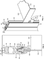
- the disclosed invention includes a shelving system with at least one vertical support supporting at least one mountable attachment member having a powered appliance, which can be configured in a variety of ways to provide a shelving system that is easy to assemble, modify, and disassemble in a variety of configurations according to the practical requirements and aesthetic tastes of its user. See Figs. 1-9 .
- Some embodiments include multiple vertical supports for connecting one or more attachment members, such as shelves, baskets, hangers, and posters, which contain powered appliances to allow a user to further customize the shelving system to a desired aesthetic.
- the shelving system can use otherwise vertical supports that are buttressed between a floor and ceiling (or other load-bearing lower and upper surfaces); see Fig. 1 .
- the shelving system can employ components of the vertical supports as horizontally-oriented supports of the shelving system ( Figs. 6-9 ); further embodiments can employ a variety of connecting elements to attach the vertically-oriented and horizontally-oriented components together.
- external connecting elements can attach the external portions of the supports.
- internal connecting elements can provide attachment in lieu of, or in addition to, external connecting elements.
- individual components of the shelving system display internal symmetry in at least one plane; that is, a component can be cut in half so that the two halves are mirror images of each other.
- individual components can display internal symmetry in in two or more planes.
- Some embodiments of the invention are directed toward the vertical supports of shelving systems having mountable attachment members with powered appliances.
- the vertical supports of these embodiments contain features that enable a user to customize a shelving system to meet her particular needs and personal tastes with minimum effort in a manner that enhances the aesthetic appeal of the shelving system while also providing power to the powered appliances in the varied configurations
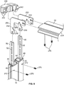
- Shelving systems generally include at least one vertically-oriented element that provides structural support. Some embodiments of the invention are directed toward a vertical support (10) that promotes ease of assembly in a variety of configurations and enhances the aesthetic appeal of the vertical support and the shelving systems it can be incorporated into, as shown in Figs. 1-5 .
- the vertical support (10) can include an external casing (20) with a first end (22) and a second end (24). When in its vertical orientation, the first end (22) is also a top end (26) and the second end (24) is also a bottom end (28) of the external casing (20).
- the external casing (20) can have a longitudinal aperture (30) that leads to a longitudinal hollow interior (38), which leads to the core (44) of the external casing (20).
- the longitudinal hollow interior (38) can include a space (40) for receiving a ladder insert and a space (42) for receiving a power delivery insert.
- the longitudinal aperture (30) is exterior to the ladder insert space (40), which is exterior to the power delivery space (42), which is exterior to the core (44).
- a vertical support (10) may have more than one longitudinal hollow interior (38) with ladder insert space (40) and power delivery insert space (42); in even more preferred embodiments, the configuration of one hollow longitudinal interior (38) with ladder insert space (40) and power delivery insert space (42) may form a mirror image of another longitudinal hollow interior (38) with ladder insert space (40) and power delivery insert space (42).
- the core (44) can be hollow at its center or can be solid.
- edges (32) of the longitudinal aperture (30) taper inward, so that the outer edges (36) of the longitudinal aperture have a greater distance between them (D1) than the distance between the inner edges (34) of the longitudinal aperture (D2).
- the edges (32) are chamfered.
- the ladder insert (50) includes a plurality of regularly spaced perforations (52) along its length.
- the ladder insert (50) can be inserted into the ladder insert space (40) so that the plurality of perforations (52) provide openings that face both the longitudinal aperture (30) and the power delivery insert space (42), providing openings between the longitudinal aperture (30) and the power delivery insert space (42).
- the ladder insert (50) When placed in the ladder insert space (40), the ladder insert (50) provides a structure by which a mountable attachment member (100), such as a shelf, hanger, or basket, having a powered appliance (120) can engage the vertical support (10).
- a mountable attachment member (100) such as a shelf, hanger, or basket, having a powered appliance (120) can engage the vertical support (10).
- one or more perforations (52) of the ladder insert (50) of the vertical support (10) engages the mountable attachment member (100) in a reversible manner; that is, the attachment member (100) can be removed from a perforation (52), if desired, and reengaged at a different perforation (52).
- the perforations (52) have a horizontal width (D3) that is greater than the horizontal width of the distance between the inner edges (34) of the longitudinal aperture (D2).
- the width (D4) of the ladder insert (50) is greater than the distance between the inner edges (34) of the longitudinal aperture (D2).
- the power delivery insert (60) provides power from a power source, such as electricity, to the powered appliance (120) that is attached to the attachment member (100).
- a power source such as electricity
- the power delivery insert (60) has a longitudinal channel (62) that faces the ladder insert space (40).
- the power delivery insert channel (62) faces the perforations (52) of the ladder insert (50).
- the power source may be an electrical outlet or may be supplied be other methods, such as by batteries (not shown).
- At least two interior sides (64) of the power delivery insert channel (62) have a power transmitter (66) to the powered appliance (120), such as a strip of electrically conductive material (68), for example strips comprising copper. It is preferred that the width of the power delivery insert channel (62) be greater than the horizontal width (D3) of the perforations (52) of the ladder insert (50), again so that there is no obstruction to prevent an attachment element (104) of an attachment member (100) from engaging the power delivery insert channel (62) after it passes through a perforation (52) of the ladder insert (50).
- the vertical support (10) engages power delivery insert channel (62) in a reversible manner; that is, the power delivery insert channel (62) can be inserted into and subsequently removed from the vertical support (10), if desired.
- the vertical support (10), with its ladder insert (50) and power delivery insert (60) provide a structure to support a mountable attachment member (100), via the ladder insert (50), and to provide power to a powered appliance (120) attached to the attachment member (100), via the power delivery insert (60).
- an attachment member (100) can comprise a shelf (102) with at least one attachment element (104), such as a bracket (106). See Figs. 4-5 .
- the attachment member (100) can comprise baskets, hangers, posters, and display monitors.
- the attachment element (104) can also have a power clip (108) having a power contact (110) on at least two sides (107) of the bracket (106), for providing power to a power cord (122) of the powered appliance (120).
- the power contact (110) is an electrical contact that conducts electricity.
- the attachment member (100) can be operatively attached to the vertical support (10) by the attachment element (104) by inserting at least one attachment element (104) through at least one perforation (52) of the ladder insert (50) and connecting the attachment element (104) to the power delivery insert channel (62) of the power delivery insert (60) so that the electrical contacts (110) of the attachment element (104) contact the power transmitter (66) on a first interior side and a second interior side (64) of the power delivery insert (60).
- power can be transmitted to the powered appliance (120).
- the attachment member (100) can be operatively attached to the vertical support (10) by the bracket (106) by inserting at least one bracket (106) through at least one perforation (52) of the ladder insert (50) and connecting the bracket (106) to the power delivery insert channel (62) of the power delivery insert (60) so that the electrical power contacts (110) of the bracket (106) contact the strips of electrically conductive material (68) on the interior sides (64) of the power delivery insert (60).
- power can be transmitted to the powered appliance (120).
- the attachment member (100) has at least two attachment elements (104) engaging the ladder insert (50).
- a shelf (102) can have a pair of brackets (106) engaging the ladder insert (50), with a power clip (108) having electrical contacts (112) transmitting power through strips of electrically conductive material (i.e., copper) (68) of the power delivery insert (60) to the powered appliance (120) of the shelf (102).
- Even more preferred embodiments may further include an external casing having a first end (22), a second end (24), and a core (44), and make power available to the powered appliance (120) through a power cord (122) connecting the powered appliance (120) to the power clip (108).
- the vertical supports (10) can be assembled with the attachment members (100) to create a shelving system (210).
- at least one vertical support can be anchored to a ceiling and floor by an anchoring mechanism (280), i.e., suction cups (282); see Fig. 1 .
- an anchoring mechanism i.e., suction cups (282); see Fig. 1 .
- Such a shelving system (210) provides display for goods or a decor unit that will support the powered appliances (120).
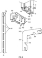
- a shelving system (210) can be assembled from at least two vertical supports (10) and at least one horizontally-oriented external casing (220), and at least one connector (230) for engaging a vertical support (10) to a horizontally-oriented external casing (220); see Figs.6-9 . It is preferred that the external casings (20) incorporated into the vertical supports (10) are identical to the horizontally-oriented external casings (220).
- the connector (230) has at least one protrusion (242), preferably a plurality of protrusions (242), that engages corresponding interior connecting spaces (49) in the external casings (20, 220).
- the connector can contain interior spaces that mate to corresponding protrusions in the external casings (not shown).
- the vertical support (10) and the horizontally-oriented external casing (220) form an angle between 60-120°, more preferred that the angle be between 75-105°, and most preferred that they form an approximate 90° (right) angle.
- the connector (230) hides the edges of the external casings (20, 220) and the internal portions of the vertical support (10) and the external casings (20, 220) from casual view, thus enhancing the aesthetic appeal of the assembled shelving system (210). See Figs. 6-7 .
- connections between the vertical supports (10) and the horizontally-oriented external casings (220) can be augmented with at least one internal connection piece (250).
- Each internal connection piece (250) can have an L-shape with two arms (252) and each arm (252) fits into the ladder insert space (40) of an external casing (20, 220).
- the internal connection piece (250) connects the vertical support (10) and the horizontally-oriented external casing (220) by simultaneously engaging the ladder insert space (40) of the vertical support (10) and the ladder insert space (40) of the horizontally-oriented external casing (220).
- the internal connection piece (250) contains at least one depression (256) on the interior face (254) of each of its arms (252). See Fig. 8 .
- the depressions (256) accommodate a fastener (270), such as a peg, screw, nail, or the like, the internal connection piece (250) to an external casing (20, 220).
- the external casings (20, 220) can have at least one fastener hole (272) to guide the fastener (270) to the depression (256) of internal connection piece (250) opposite it.
- At least two internal connection pieces (250) are used to augment the connection between each vertical support (10) and horizontally-oriented external casing (220).
- the two internal connection pieces (250) have at least two dimensions of the same size as the ladder insert (50), i.e., width and depth.
- the individual components of the vertical support (10) and its individual components can be made separately, by different methods incorporating different materials.
- the individual components be made such that each component have internal symmetry in at least one plane; that is, each component can be cut in half so that the two halves are mirror images of each other.
- individual components can display internal symmetry in in two or more planes.
- This internal symmetry means that a component can be operatively inserted into its place in the vertical support (10) in multiple orientations.
- a preferred embodiment of a ladder insert (50) is symmetrical along both its horizontal and vertical planes; thus it can perform the function of supporting an attachment member (100) regardless of whether it is inserted into the ladder insert space (40) "rightside-up” or “upside-down” or whether it faces “forward” or “backward.”
- the internal symmetry of the individual components (and the spaces into which they engage the vertical support (10)) increases the ease of assembly and the number of configurations a shelving system (210) can attain.
- the internal symmetry of the vertical support (10) enhances the ease of assembly and the number of configurations a shelving system (210) can attain, as well as enhancing the aesthetic appeal of the assembled shelving system (210).
- the vertical support (10) has internal symmetry in at least one plane, and even more preferably, in two or more planes.
Landscapes
- Engineering & Computer Science (AREA)
- Power Engineering (AREA)
- Display Racks (AREA)
- Ladders (AREA)
- Warehouses Or Storage Devices (AREA)
Applications Claiming Priority (1)
| Application Number | Priority Date | Filing Date | Title |
|---|---|---|---|
| US15/137,825 US9831642B2 (en) | 2016-04-25 | 2016-04-25 | Vertical support for shelving system and shelving system |
Publications (2)
| Publication Number | Publication Date |
|---|---|
| EP3238567A1 true EP3238567A1 (fr) | 2017-11-01 |
| EP3238567B1 EP3238567B1 (fr) | 2019-07-17 |
Family
ID=58108475
Family Applications (1)
| Application Number | Title | Priority Date | Filing Date |
|---|---|---|---|
| EP17157180.5A Active EP3238567B1 (fr) | 2016-04-25 | 2017-02-21 | Support vertical pour système d'étagère et système d'étagère |
Country Status (4)
| Country | Link |
|---|---|
| US (1) | US9831642B2 (fr) |
| EP (1) | EP3238567B1 (fr) |
| CA (1) | CA2964657C (fr) |
| MX (1) | MX376502B (fr) |
Cited By (2)
| Publication number | Priority date | Publication date | Assignee | Title |
|---|---|---|---|---|
| FR3082715A1 (fr) * | 2019-01-15 | 2019-12-27 | France Decors | Console de crémaillère configurée pour recevoir et électrifier une tablette |
| IT202100013856A1 (it) * | 2021-05-27 | 2022-11-27 | Poliform S P A | Montante per elemento di arredo |
Families Citing this family (26)
| Publication number | Priority date | Publication date | Assignee | Title |
|---|---|---|---|---|
| US9119471B2 (en) | 2013-03-14 | 2015-09-01 | Spg International Llc | Support bracket |
| CN108477854A (zh) | 2013-10-01 | 2018-09-04 | Spg国际有限责任公司 | 搁架系统 |
| CN107524965B (zh) * | 2016-06-22 | 2024-04-05 | 赛尔富电子有限公司 | 一种使用led灯具的货架的取电系统 |
| DE102016124956A1 (de) * | 2016-12-20 | 2018-06-21 | Rehau Ag + Co | System zur Bestromung mehrerer elektronischer Anzeigeeinrichtungen zur Anzeige von produktbezogenen Informationen und Warenpräsentationssystem |
| CN110494910B (zh) * | 2017-01-13 | 2021-09-17 | 达科电子股份有限公司 | 横幅显示器 |
| US10709237B2 (en) | 2017-02-17 | 2020-07-14 | Intermetro Industries Corporation | Cantilever shelving system |
| US10021972B1 (en) * | 2017-02-17 | 2018-07-17 | Intermetro Industries Corporation | Cantilever shelving system |
| DE102017107379A1 (de) * | 2017-04-06 | 2018-10-11 | Grob & Hoffmann GmbH | Beleuchtetes Regalsystem |
| US11122897B2 (en) * | 2017-04-07 | 2021-09-21 | RCS Syslems, Inc. | Display mounting system and method of manufacturing outriggers |
| USD869882S1 (en) * | 2017-07-13 | 2019-12-17 | Modern Equipment Co., Inc. | Display shelving |
| US10492631B2 (en) * | 2017-07-13 | 2019-12-03 | Black & Decker Inc. | Wall hanging system |
| WO2019053206A1 (fr) * | 2017-09-15 | 2019-03-21 | Lego A/S | Système de rayonnage |
| USD832613S1 (en) * | 2017-09-22 | 2018-11-06 | Williams-Sonoma, Inc. | Wall unit |
| US11091958B2 (en) * | 2018-01-10 | 2021-08-17 | Sub-Zero Group, Inc. | Shelf electrical signal connector |
| CN208640326U (zh) * | 2018-05-14 | 2019-03-26 | 刘晓涵 | 一种顶天立地式置物架 |
| US10952534B2 (en) * | 2018-06-22 | 2021-03-23 | Product Miniature, Inc. | Low voltage modular shelf system |
| US10646058B2 (en) * | 2018-07-09 | 2020-05-12 | Vira Insight, Llc | Retail display system with power supply interface |
| US10665988B2 (en) * | 2018-08-08 | 2020-05-26 | Hyperframe Inc. | Framing assembly with modular connectors |
| US10646035B1 (en) * | 2018-09-21 | 2020-05-12 | Steve Schindehette | Overhead storage system and method |
| US10905234B1 (en) * | 2018-09-21 | 2021-02-02 | Steven Schindehette | Overhead storage system and method |
| JP2020156867A (ja) * | 2019-03-27 | 2020-10-01 | パナソニックIpマネジメント株式会社 | 給電フレームおよび給電フレーム装置 |
| JP2020156868A (ja) * | 2019-03-27 | 2020-10-01 | パナソニックIpマネジメント株式会社 | 棚板給電装置 |
| CA3088021A1 (fr) * | 2019-07-26 | 2021-01-26 | Enzo Vardaro | Ensemble de panneau arriere modulaire pour structure d`affichage |
| US11737586B1 (en) * | 2022-02-03 | 2023-08-29 | Imageworks Display And Marketing Group, Inc. | Merchandise display stand |
| JP2024018743A (ja) * | 2022-07-29 | 2024-02-08 | 株式会社ニトリホールディングス | 突っ張り支柱および壁面収納装置 |
| EP4601513A1 (fr) * | 2022-10-14 | 2025-08-20 | L. & S. Italia S.p.A. | Système de support de tablette |
Citations (8)
| Publication number | Priority date | Publication date | Assignee | Title |
|---|---|---|---|---|
| CH601930A5 (en) * | 1975-10-08 | 1978-07-14 | Fehlbaum & Co | Hollow profile shelf rail |
| US6527565B1 (en) * | 2000-08-11 | 2003-03-04 | Robert L. Johns | Adjustable light display assembly |
| WO2005099522A2 (fr) * | 2004-04-19 | 2005-10-27 | Charles Daniel | Systeme de tablette |
| DE102007028395A1 (de) * | 2007-06-15 | 2008-12-18 | Brinkmann, Wolfgang | Etagenträgersystem |
| EP2092853A2 (fr) * | 2008-02-20 | 2009-08-26 | Konrad Knoblauch Vermögensverwaltung GmbH | Rail profilé |
| WO2011150309A2 (fr) * | 2010-05-28 | 2011-12-01 | Steelcase Inc. | Système de paroi de travail de bureau |
| US20140224875A1 (en) * | 2013-02-12 | 2014-08-14 | Powerwall Inc. | Shelf power system |
| EP2842461A1 (fr) * | 2013-08-29 | 2015-03-04 | DongGuan HengLong Fixture Manufacturing Company LTD | Présentoir électrique avec système d'éclairage |
Family Cites Families (41)
| Publication number | Priority date | Publication date | Assignee | Title |
|---|---|---|---|---|
| US2441461A (en) | 1945-11-19 | 1948-05-11 | Wayne Anthony | Electric utility connection |
| US2890266A (en) * | 1955-03-01 | 1959-06-09 | Minnesota Mining & Mfg | Wire-connector |
| US3559149A (en) | 1968-10-29 | 1971-01-26 | Jack L Shagena Jr | Electrically wired baseboard |
| DE2234435C2 (de) | 1971-08-03 | 1983-04-28 | Staff GmbH & Co KG, 4920 Lemgo | Überbrückungsadapter für Stromverteilerschienen |
| US4096349A (en) | 1977-04-04 | 1978-06-20 | Lightolier Incorporated | Flexible connector for track lighting systems |
| FR2423074A1 (fr) | 1978-04-14 | 1979-11-09 | Lampes Sa | Systeme d'accessoires de raccordement pour rail d'alimentation electrique a profil asymetrique |
| DE2966388D1 (en) | 1978-07-21 | 1983-12-15 | Electrak Int Ltd | Electrical distribution system |
| US4239932A (en) | 1979-01-18 | 1980-12-16 | Gf Business Equipment, Inc. | Partition wiring system |
| US4245874A (en) * | 1979-03-05 | 1981-01-20 | Mcgraw-Edison | Flexible connector assembly for track lighting system |
| US4312086A (en) * | 1980-02-22 | 1982-01-26 | George Nagem | Modular furniture |
| US4553809A (en) * | 1984-09-24 | 1985-11-19 | Raychem Corporation | Electrical connector |
| US4919625A (en) | 1988-04-29 | 1990-04-24 | Cooper Industries, Inc. | Track lighting apparatus |
| US4982054A (en) * | 1988-10-06 | 1991-01-01 | Raychem Corporation | Telecommunications pedestal closure with environmental control liner |
| US4973796A (en) * | 1989-08-10 | 1990-11-27 | Visu-Wall By Hbsa Industries, Inc. | Electrified wall structure |
| US5308922A (en) * | 1992-06-08 | 1994-05-03 | Reactive Industries, Inc. | Wire connector and method of manufacture |
| EP0588654A3 (fr) * | 1992-09-17 | 1995-05-24 | Howden Wesley Farham | Connecteur électrique. |
| MX9304688A (es) | 1993-01-08 | 1994-08-31 | Jacques Nadeau | Sistema distribuidor electrico. |
| US5695261A (en) * | 1996-04-12 | 1997-12-09 | Slesinger; Bruce M. | Integrally powered modular furniture |
| US5921190A (en) | 1997-01-17 | 1999-07-13 | Stamford Investments, Inc. | Modular display system |
| US6033239A (en) | 1998-10-16 | 2000-03-07 | Jaakkola; Risto | Connector for track lighting systems |
| CN1310497A (zh) | 2000-02-21 | 2001-08-29 | 家电宝有限公司 | 轨道灯具的供电接头 |
| US6244733B1 (en) | 2000-02-25 | 2001-06-12 | Juno Manufacturing, Inc. | Low voltage track lighting system |
| WO2003053192A1 (fr) * | 2001-12-08 | 2003-07-03 | Rittal Gmbh & Co. Kg | Profile de bati |
| US6644988B2 (en) * | 2002-02-20 | 2003-11-11 | Rafael Healy | Fabricated baseplate for electrical installations |
| US20030224636A1 (en) * | 2002-05-29 | 2003-12-04 | Lorenzen John F. | Movable utility receptacle system |
| US6716042B2 (en) * | 2002-07-05 | 2004-04-06 | Michael Lin | Track system of projector lamp and electrical connection device assembly thereof |
| US6813896B1 (en) | 2003-07-30 | 2004-11-09 | Whirlpool Corporation | Power bus for removable refrigerator shelves |
| DE20314260U1 (de) * | 2003-09-15 | 2003-11-13 | Visplay International Ag, Muttenz | Profilschiene und damit erstellte Präsentationsvorrichtung |
| US7056007B2 (en) * | 2004-05-13 | 2006-06-06 | Hwa Jung Chiu | Track lamp assembly and display with the track lamp assembly |
| US20080043456A1 (en) * | 2006-08-15 | 2008-02-21 | Bernardini Allen J | Shelf light bracket connector system |
| US20090152944A1 (en) * | 2007-07-26 | 2009-06-18 | Rubbermaid, Inc. | Power system |
| US8172589B2 (en) * | 2007-08-09 | 2012-05-08 | Haworth, Inc. | Modular electrical distribution system for a building |
| US7654834B1 (en) | 2008-05-05 | 2010-02-02 | Genlyte Thomas Group, Llc | Track lighting assembly |
| US8154856B2 (en) * | 2009-12-16 | 2012-04-10 | Lineage Power Corporation | Cabinet for a power distribution system |
| US9204736B2 (en) * | 2012-08-22 | 2015-12-08 | Streater LLC | Shelving unit lighting system |
| DE202012008355U1 (de) * | 2012-09-03 | 2012-10-24 | Visplay International Ag | Aufhängevorriichtung zur Warenpräsentation mit einer stromführenden Profilschiene und darin einhängbarem Primärträger |
| US8967740B2 (en) | 2013-02-07 | 2015-03-03 | Whirlpool Corporation | Electrical connector for adjustable refrigerator shelf |
| KR20230020552A (ko) | 2013-06-20 | 2023-02-10 | 젬트론 코포레이션 | 가전기기 조명용 조명기구 |
| DE102013114289B4 (de) | 2013-12-18 | 2023-09-07 | Juvema Ag | Regalsystem mit elektrischer Versorgung |
| US9680270B2 (en) * | 2014-05-15 | 2017-06-13 | Elmer A. Wessel | Apparatus for enhanced merchandise display |
| US9537274B1 (en) * | 2016-02-16 | 2017-01-03 | Elemental LED, Inc. | Modular power and connector system for lighting elements |
-
2016
- 2016-04-25 US US15/137,825 patent/US9831642B2/en active Active
-
2017
- 2017-02-21 EP EP17157180.5A patent/EP3238567B1/fr active Active
- 2017-04-19 CA CA2964657A patent/CA2964657C/fr active Active
- 2017-04-24 MX MX2017005317A patent/MX376502B/es active IP Right Grant
Patent Citations (8)
| Publication number | Priority date | Publication date | Assignee | Title |
|---|---|---|---|---|
| CH601930A5 (en) * | 1975-10-08 | 1978-07-14 | Fehlbaum & Co | Hollow profile shelf rail |
| US6527565B1 (en) * | 2000-08-11 | 2003-03-04 | Robert L. Johns | Adjustable light display assembly |
| WO2005099522A2 (fr) * | 2004-04-19 | 2005-10-27 | Charles Daniel | Systeme de tablette |
| DE102007028395A1 (de) * | 2007-06-15 | 2008-12-18 | Brinkmann, Wolfgang | Etagenträgersystem |
| EP2092853A2 (fr) * | 2008-02-20 | 2009-08-26 | Konrad Knoblauch Vermögensverwaltung GmbH | Rail profilé |
| WO2011150309A2 (fr) * | 2010-05-28 | 2011-12-01 | Steelcase Inc. | Système de paroi de travail de bureau |
| US20140224875A1 (en) * | 2013-02-12 | 2014-08-14 | Powerwall Inc. | Shelf power system |
| EP2842461A1 (fr) * | 2013-08-29 | 2015-03-04 | DongGuan HengLong Fixture Manufacturing Company LTD | Présentoir électrique avec système d'éclairage |
Cited By (2)
| Publication number | Priority date | Publication date | Assignee | Title |
|---|---|---|---|---|
| FR3082715A1 (fr) * | 2019-01-15 | 2019-12-27 | France Decors | Console de crémaillère configurée pour recevoir et électrifier une tablette |
| IT202100013856A1 (it) * | 2021-05-27 | 2022-11-27 | Poliform S P A | Montante per elemento di arredo |
Also Published As
| Publication number | Publication date |
|---|---|
| EP3238567B1 (fr) | 2019-07-17 |
| US20170310090A1 (en) | 2017-10-26 |
| MX376502B (es) | 2025-03-07 |
| MX2017005317A (es) | 2018-08-20 |
| CA2964657A1 (fr) | 2017-10-25 |
| CA2964657C (fr) | 2023-10-03 |
| US9831642B2 (en) | 2017-11-28 |
Similar Documents
| Publication | Publication Date | Title |
|---|---|---|
| CA2964657C (fr) | Support vertical de systeme d'etagere et systeme d'etagere | |
| US11291312B2 (en) | Low product indicator for self facing merchandiser and related methods | |
| US5509541A (en) | Bracket construction | |
| US8984781B2 (en) | Configurable large-depth panel display | |
| US20130299439A1 (en) | Powering Assembly and Method For Adjustable Shelving | |
| ES2691714T3 (es) | Instalación de presentación, en particular para productos | |
| US9357858B2 (en) | Low voltage plug and play display system | |
| EP1891876B1 (fr) | Système d'affichage de produit de carte | |
| US7600895B2 (en) | Light display unit with fixture and light strand | |
| US11160406B2 (en) | Display hanger for slide style shoes | |
| US6280066B1 (en) | Lamp display system | |
| KR20050021636A (ko) | 월판넬과 포인트 시스템으로 구성되는 상품진열대 | |
| AU3816302A (en) | Modular display rack | |
| US6767234B1 (en) | Hook and hang display system with plug-in bullnose header module | |
| US11122897B2 (en) | Display mounting system and method of manufacturing outriggers | |
| US20170150831A1 (en) | Display card for articles of jewelry | |
| CA2387684C (fr) | Systeme d'exposition de lampe | |
| KR101353510B1 (ko) | 스마트 기능을 갖는 이미용 경대 | |
| TWI506401B (zh) | 背架模組 | |
| CN106466085B (zh) | 具有增强缆索设备和支承壳体的展示装置 | |
| KR20180067099A (ko) | 물품 진열구대 | |
| KR101699759B1 (ko) | 상품 진열대 | |
| GB2349803A (en) | Shelf structure | |
| TWI526805B (zh) | Backstop module | |
| KR20100002592U (ko) | 진열함 |
Legal Events
| Date | Code | Title | Description |
|---|---|---|---|
| PUAI | Public reference made under article 153(3) epc to a published international application that has entered the european phase |
Free format text: ORIGINAL CODE: 0009012 |
|
| STAA | Information on the status of an ep patent application or granted ep patent |
Free format text: STATUS: THE APPLICATION HAS BEEN PUBLISHED |
|
| AK | Designated contracting states |
Kind code of ref document: A1 Designated state(s): AL AT BE BG CH CY CZ DE DK EE ES FI FR GB GR HR HU IE IS IT LI LT LU LV MC MK MT NL NO PL PT RO RS SE SI SK SM TR |
|
| AX | Request for extension of the european patent |
Extension state: BA ME |
|
| STAA | Information on the status of an ep patent application or granted ep patent |
Free format text: STATUS: REQUEST FOR EXAMINATION WAS MADE |
|
| 17P | Request for examination filed |
Effective date: 20180105 |
|
| RBV | Designated contracting states (corrected) |
Designated state(s): AL AT BE BG CH CY CZ DE DK EE ES FI FR GB GR HR HU IE IS IT LI LT LU LV MC MK MT NL NO PL PT RO RS SE SI SK SM TR |
|
| STAA | Information on the status of an ep patent application or granted ep patent |
Free format text: STATUS: EXAMINATION IS IN PROGRESS |
|
| 17Q | First examination report despatched |
Effective date: 20180703 |
|
| RIN1 | Information on inventor provided before grant (corrected) |
Inventor name: WELLS, NATHAN Inventor name: WOOD, GRAHAM Inventor name: WOODLEY, BRETT Inventor name: HALLER, ERICH |
|
| GRAP | Despatch of communication of intention to grant a patent |
Free format text: ORIGINAL CODE: EPIDOSNIGR1 |
|
| STAA | Information on the status of an ep patent application or granted ep patent |
Free format text: STATUS: GRANT OF PATENT IS INTENDED |
|
| INTG | Intention to grant announced |
Effective date: 20181120 |
|
| GRAJ | Information related to disapproval of communication of intention to grant by the applicant or resumption of examination proceedings by the epo deleted |
Free format text: ORIGINAL CODE: EPIDOSDIGR1 |
|
| STAA | Information on the status of an ep patent application or granted ep patent |
Free format text: STATUS: EXAMINATION IS IN PROGRESS |
|
| INTC | Intention to grant announced (deleted) | ||
| GRAP | Despatch of communication of intention to grant a patent |
Free format text: ORIGINAL CODE: EPIDOSNIGR1 |
|
| STAA | Information on the status of an ep patent application or granted ep patent |
Free format text: STATUS: GRANT OF PATENT IS INTENDED |
|
| INTG | Intention to grant announced |
Effective date: 20190430 |
|
| GRAA | (expected) grant |
Free format text: ORIGINAL CODE: 0009210 |
|
| STAA | Information on the status of an ep patent application or granted ep patent |
Free format text: STATUS: THE PATENT HAS BEEN GRANTED |
|
| AK | Designated contracting states |
Kind code of ref document: B1 Designated state(s): AL AT BE BG CH CY CZ DE DK EE ES FI FR GB GR HR HU IE IS IT LI LT LU LV MC MK MT NL NO PL PT RO RS SE SI SK SM TR |
|
| REG | Reference to a national code |
Ref country code: GB Ref legal event code: FG4D |
|
| REG | Reference to a national code |
Ref country code: CH Ref legal event code: EP |
|
| REG | Reference to a national code |
Ref country code: DE Ref legal event code: R096 Ref document number: 602017005255 Country of ref document: DE |
|
| REG | Reference to a national code |
Ref country code: IE Ref legal event code: FG4D |
|
| REG | Reference to a national code |
Ref country code: AT Ref legal event code: REF Ref document number: 1155023 Country of ref document: AT Kind code of ref document: T Effective date: 20190815 |
|
| REG | Reference to a national code |
Ref country code: NL Ref legal event code: MP Effective date: 20190717 |
|
| REG | Reference to a national code |
Ref country code: LT Ref legal event code: MG4D |
|
| REG | Reference to a national code |
Ref country code: AT Ref legal event code: MK05 Ref document number: 1155023 Country of ref document: AT Kind code of ref document: T Effective date: 20190717 |
|
| PG25 | Lapsed in a contracting state [announced via postgrant information from national office to epo] |
Ref country code: FI Free format text: LAPSE BECAUSE OF FAILURE TO SUBMIT A TRANSLATION OF THE DESCRIPTION OR TO PAY THE FEE WITHIN THE PRESCRIBED TIME-LIMIT Effective date: 20190717 Ref country code: BG Free format text: LAPSE BECAUSE OF FAILURE TO SUBMIT A TRANSLATION OF THE DESCRIPTION OR TO PAY THE FEE WITHIN THE PRESCRIBED TIME-LIMIT Effective date: 20191017 Ref country code: SE Free format text: LAPSE BECAUSE OF FAILURE TO SUBMIT A TRANSLATION OF THE DESCRIPTION OR TO PAY THE FEE WITHIN THE PRESCRIBED TIME-LIMIT Effective date: 20190717 Ref country code: AT Free format text: LAPSE BECAUSE OF FAILURE TO SUBMIT A TRANSLATION OF THE DESCRIPTION OR TO PAY THE FEE WITHIN THE PRESCRIBED TIME-LIMIT Effective date: 20190717 Ref country code: HR Free format text: LAPSE BECAUSE OF FAILURE TO SUBMIT A TRANSLATION OF THE DESCRIPTION OR TO PAY THE FEE WITHIN THE PRESCRIBED TIME-LIMIT Effective date: 20190717 Ref country code: NO Free format text: LAPSE BECAUSE OF FAILURE TO SUBMIT A TRANSLATION OF THE DESCRIPTION OR TO PAY THE FEE WITHIN THE PRESCRIBED TIME-LIMIT Effective date: 20191017 Ref country code: LT Free format text: LAPSE BECAUSE OF FAILURE TO SUBMIT A TRANSLATION OF THE DESCRIPTION OR TO PAY THE FEE WITHIN THE PRESCRIBED TIME-LIMIT Effective date: 20190717 Ref country code: PT Free format text: LAPSE BECAUSE OF FAILURE TO SUBMIT A TRANSLATION OF THE DESCRIPTION OR TO PAY THE FEE WITHIN THE PRESCRIBED TIME-LIMIT Effective date: 20191118 Ref country code: NL Free format text: LAPSE BECAUSE OF FAILURE TO SUBMIT A TRANSLATION OF THE DESCRIPTION OR TO PAY THE FEE WITHIN THE PRESCRIBED TIME-LIMIT Effective date: 20190717 |
|
| PG25 | Lapsed in a contracting state [announced via postgrant information from national office to epo] |
Ref country code: GR Free format text: LAPSE BECAUSE OF FAILURE TO SUBMIT A TRANSLATION OF THE DESCRIPTION OR TO PAY THE FEE WITHIN THE PRESCRIBED TIME-LIMIT Effective date: 20191018 Ref country code: LV Free format text: LAPSE BECAUSE OF FAILURE TO SUBMIT A TRANSLATION OF THE DESCRIPTION OR TO PAY THE FEE WITHIN THE PRESCRIBED TIME-LIMIT Effective date: 20190717 Ref country code: AL Free format text: LAPSE BECAUSE OF FAILURE TO SUBMIT A TRANSLATION OF THE DESCRIPTION OR TO PAY THE FEE WITHIN THE PRESCRIBED TIME-LIMIT Effective date: 20190717 Ref country code: ES Free format text: LAPSE BECAUSE OF FAILURE TO SUBMIT A TRANSLATION OF THE DESCRIPTION OR TO PAY THE FEE WITHIN THE PRESCRIBED TIME-LIMIT Effective date: 20190717 Ref country code: RS Free format text: LAPSE BECAUSE OF FAILURE TO SUBMIT A TRANSLATION OF THE DESCRIPTION OR TO PAY THE FEE WITHIN THE PRESCRIBED TIME-LIMIT Effective date: 20190717 Ref country code: IS Free format text: LAPSE BECAUSE OF FAILURE TO SUBMIT A TRANSLATION OF THE DESCRIPTION OR TO PAY THE FEE WITHIN THE PRESCRIBED TIME-LIMIT Effective date: 20191117 |
|
| PG25 | Lapsed in a contracting state [announced via postgrant information from national office to epo] |
Ref country code: TR Free format text: LAPSE BECAUSE OF FAILURE TO SUBMIT A TRANSLATION OF THE DESCRIPTION OR TO PAY THE FEE WITHIN THE PRESCRIBED TIME-LIMIT Effective date: 20190717 |
|
| PG25 | Lapsed in a contracting state [announced via postgrant information from national office to epo] |
Ref country code: RO Free format text: LAPSE BECAUSE OF FAILURE TO SUBMIT A TRANSLATION OF THE DESCRIPTION OR TO PAY THE FEE WITHIN THE PRESCRIBED TIME-LIMIT Effective date: 20190717 Ref country code: PL Free format text: LAPSE BECAUSE OF FAILURE TO SUBMIT A TRANSLATION OF THE DESCRIPTION OR TO PAY THE FEE WITHIN THE PRESCRIBED TIME-LIMIT Effective date: 20190717 Ref country code: EE Free format text: LAPSE BECAUSE OF FAILURE TO SUBMIT A TRANSLATION OF THE DESCRIPTION OR TO PAY THE FEE WITHIN THE PRESCRIBED TIME-LIMIT Effective date: 20190717 Ref country code: IT Free format text: LAPSE BECAUSE OF FAILURE TO SUBMIT A TRANSLATION OF THE DESCRIPTION OR TO PAY THE FEE WITHIN THE PRESCRIBED TIME-LIMIT Effective date: 20190717 Ref country code: DK Free format text: LAPSE BECAUSE OF FAILURE TO SUBMIT A TRANSLATION OF THE DESCRIPTION OR TO PAY THE FEE WITHIN THE PRESCRIBED TIME-LIMIT Effective date: 20190717 |
|
| PG25 | Lapsed in a contracting state [announced via postgrant information from national office to epo] |
Ref country code: SK Free format text: LAPSE BECAUSE OF FAILURE TO SUBMIT A TRANSLATION OF THE DESCRIPTION OR TO PAY THE FEE WITHIN THE PRESCRIBED TIME-LIMIT Effective date: 20190717 Ref country code: CZ Free format text: LAPSE BECAUSE OF FAILURE TO SUBMIT A TRANSLATION OF THE DESCRIPTION OR TO PAY THE FEE WITHIN THE PRESCRIBED TIME-LIMIT Effective date: 20190717 Ref country code: SM Free format text: LAPSE BECAUSE OF FAILURE TO SUBMIT A TRANSLATION OF THE DESCRIPTION OR TO PAY THE FEE WITHIN THE PRESCRIBED TIME-LIMIT Effective date: 20190717 Ref country code: IS Free format text: LAPSE BECAUSE OF FAILURE TO SUBMIT A TRANSLATION OF THE DESCRIPTION OR TO PAY THE FEE WITHIN THE PRESCRIBED TIME-LIMIT Effective date: 20200224 |
|
| REG | Reference to a national code |
Ref country code: DE Ref legal event code: R097 Ref document number: 602017005255 Country of ref document: DE |
|
| PLBE | No opposition filed within time limit |
Free format text: ORIGINAL CODE: 0009261 |
|
| STAA | Information on the status of an ep patent application or granted ep patent |
Free format text: STATUS: NO OPPOSITION FILED WITHIN TIME LIMIT |
|
| PG2D | Information on lapse in contracting state deleted |
Ref country code: IS |
|
| 26N | No opposition filed |
Effective date: 20200603 |
|
| PG25 | Lapsed in a contracting state [announced via postgrant information from national office to epo] |
Ref country code: SI Free format text: LAPSE BECAUSE OF FAILURE TO SUBMIT A TRANSLATION OF THE DESCRIPTION OR TO PAY THE FEE WITHIN THE PRESCRIBED TIME-LIMIT Effective date: 20190717 |
|
| REG | Reference to a national code |
Ref country code: DE Ref legal event code: R119 Ref document number: 602017005255 Country of ref document: DE |
|
| REG | Reference to a national code |
Ref country code: CH Ref legal event code: PL |
|
| REG | Reference to a national code |
Ref country code: BE Ref legal event code: MM Effective date: 20200229 |
|
| PG25 | Lapsed in a contracting state [announced via postgrant information from national office to epo] |
Ref country code: LU Free format text: LAPSE BECAUSE OF NON-PAYMENT OF DUE FEES Effective date: 20200221 Ref country code: MC Free format text: LAPSE BECAUSE OF FAILURE TO SUBMIT A TRANSLATION OF THE DESCRIPTION OR TO PAY THE FEE WITHIN THE PRESCRIBED TIME-LIMIT Effective date: 20190717 |
|
| PG25 | Lapsed in a contracting state [announced via postgrant information from national office to epo] |
Ref country code: CH Free format text: LAPSE BECAUSE OF NON-PAYMENT OF DUE FEES Effective date: 20200229 Ref country code: LI Free format text: LAPSE BECAUSE OF NON-PAYMENT OF DUE FEES Effective date: 20200229 |
|
| PG25 | Lapsed in a contracting state [announced via postgrant information from national office to epo] |
Ref country code: FR Free format text: LAPSE BECAUSE OF NON-PAYMENT OF DUE FEES Effective date: 20200229 Ref country code: DE Free format text: LAPSE BECAUSE OF NON-PAYMENT OF DUE FEES Effective date: 20200901 Ref country code: IE Free format text: LAPSE BECAUSE OF NON-PAYMENT OF DUE FEES Effective date: 20200221 |
|
| PG25 | Lapsed in a contracting state [announced via postgrant information from national office to epo] |
Ref country code: BE Free format text: LAPSE BECAUSE OF NON-PAYMENT OF DUE FEES Effective date: 20200229 |
|
| GBPC | Gb: european patent ceased through non-payment of renewal fee |
Effective date: 20210221 |
|
| PG25 | Lapsed in a contracting state [announced via postgrant information from national office to epo] |
Ref country code: GB Free format text: LAPSE BECAUSE OF NON-PAYMENT OF DUE FEES Effective date: 20210221 |
|
| PG25 | Lapsed in a contracting state [announced via postgrant information from national office to epo] |
Ref country code: MT Free format text: LAPSE BECAUSE OF FAILURE TO SUBMIT A TRANSLATION OF THE DESCRIPTION OR TO PAY THE FEE WITHIN THE PRESCRIBED TIME-LIMIT Effective date: 20190717 Ref country code: CY Free format text: LAPSE BECAUSE OF FAILURE TO SUBMIT A TRANSLATION OF THE DESCRIPTION OR TO PAY THE FEE WITHIN THE PRESCRIBED TIME-LIMIT Effective date: 20190717 |
|
| PG25 | Lapsed in a contracting state [announced via postgrant information from national office to epo] |
Ref country code: MK Free format text: LAPSE BECAUSE OF FAILURE TO SUBMIT A TRANSLATION OF THE DESCRIPTION OR TO PAY THE FEE WITHIN THE PRESCRIBED TIME-LIMIT Effective date: 20190717 |