EP3238570A1 - Verfahren zum entwurf eines rückenlehnenbewegungsmechanismus und damit entworfener rückenlehnenbewegungsmechanismus - Google Patents
Verfahren zum entwurf eines rückenlehnenbewegungsmechanismus und damit entworfener rückenlehnenbewegungsmechanismus Download PDFInfo
- Publication number
- EP3238570A1 EP3238570A1 EP15871731.4A EP15871731A EP3238570A1 EP 3238570 A1 EP3238570 A1 EP 3238570A1 EP 15871731 A EP15871731 A EP 15871731A EP 3238570 A1 EP3238570 A1 EP 3238570A1
- Authority
- EP
- European Patent Office
- Prior art keywords
- backrest
- movement
- movement mechanism
- frame
- upper frame
- Prior art date
- Legal status (The legal status is an assumption and is not a legal conclusion. Google has not performed a legal analysis and makes no representation as to the accuracy of the status listed.)
- Withdrawn
Links
Images


Classifications
-
- A—HUMAN NECESSITIES
- A47—FURNITURE; DOMESTIC ARTICLES OR APPLIANCES; COFFEE MILLS; SPICE MILLS; SUCTION CLEANERS IN GENERAL
- A47C—CHAIRS; SOFAS; BEDS
- A47C1/00—Chairs adapted for special purposes
- A47C1/02—Reclining or easy chairs
- A47C1/022—Reclining or easy chairs having independently-adjustable supporting parts
- A47C1/024—Reclining or easy chairs having independently-adjustable supporting parts the parts, being the back-rest, or the back-rest and seat unit, having adjustable inclination
- A47C1/0242—Reclining or easy chairs having independently-adjustable supporting parts the parts, being the back-rest, or the back-rest and seat unit, having adjustable inclination by electric motors
-
- A—HUMAN NECESSITIES
- A47—FURNITURE; DOMESTIC ARTICLES OR APPLIANCES; COFFEE MILLS; SPICE MILLS; SUCTION CLEANERS IN GENERAL
- A47C—CHAIRS; SOFAS; BEDS
- A47C1/00—Chairs adapted for special purposes
- A47C1/02—Reclining or easy chairs
- A47C1/031—Reclining or easy chairs having coupled concurrently adjustable supporting parts
- A47C1/032—Reclining or easy chairs having coupled concurrently adjustable supporting parts the parts being movably-coupled seat and back-rest
-
- A—HUMAN NECESSITIES
- A47—FURNITURE; DOMESTIC ARTICLES OR APPLIANCES; COFFEE MILLS; SPICE MILLS; SUCTION CLEANERS IN GENERAL
- A47C—CHAIRS; SOFAS; BEDS
- A47C20/00—Head-, foot- or like rests for beds, sofas or the like
- A47C20/04—Head-, foot- or like rests for beds, sofas or the like with adjustable inclination
Definitions
- the present invention relates to a method for designing a backrest movement mechanism and a backrest movement mechanism designed using same, more particularly, to a backrest movement mechanism applicable to a seat or a bed.
- the present invention relates to the adjustable backrest type, an included angle between the backrest and a seat cushion is adjustable, or the backrest and the seat cushion may have a relative movement. All existing connecting mechanisms between the backrest and the seat cushion are revolute pair or turning pair, which may also be called a hinge, and more particularly, a hinge type, a pin shaft type, a screw stem type, etc. are comprised.
- the present invention provides a method for designing a backrest movement mechanism and a backrest movement mechanism designed using the method.
- a rotating point of a connecting mechanism is very close to a rotating point of a human body. Therefore, the back of the human body can be comfortably in contact with the backrest, and the relative displacement is eliminated, so as to give the user comfortable experience.
- the backrest movement mechanism designed according to the method above includes an upper frame and a backrest frame, and further includes the backrest connecting mechanism, wherein the backrest frame is movably connected to the upper frame via the backrest connecting mechanism and moves along the movement track relative to the upper frame.
- the movement track is a long hole approximately in conformity with the second arc.
- the backrest frame is provided with a pin shaft matched with a long hole on the backrest connecting mechanism, and the movement of the backrest frame is limited in the long hole via the pin shaft.
- the backrest connecting mechanisms are used in pairs, and are respectively arranged on two sides of the upper frame.
- the backrest connecting mechanism is also provided with two connecting holes, and the backrest connecting mechanism is fixed on the upper frame via the connecting holes.
- the backrest connecting mechanism is falciform or semicircular.
- the backrest movement mechanism further includes a driving link for driving the backrest frame, wherein two ends of the driving link are movably connected to the backrest frame and the upper frame via connecting plates respectively.
- the backrest movement mechanism further includes a supporting rod, wherein two ends of the supporting rod are rotationally connected to the backrest frame and the upper frame via the connecting plates respectively.
- the present invention has the beneficial effects that: compared with the existing products, the present invention improves the technical defects of the original products, and creatively changes the motion between the backrest and the seat cushion from a revolute pair to a sliding pair with reference to an ergonomics idea.
- a mechanical rotating point between the backrest and the seat cushion is as close as possible to a rotating point of the human body, so that when the human body moves from sitting to lying or from lying to sitting, the back of the human body can be comfortably in contact with the backrest, and accordingly the relative displacement caused by the relative motion between the back of the user and the backrest can be minimized, so as to minimize the "back rubbing sensation", thereby giving the user the best and most comfortable experience.
- the present invention designs a backrest movement mechanism via analyzing the movement trail of a point A which bears the largest body pressure on a human spine.
- the inventor takes a man with a height of 167cm as a research object, and the method particularly includes the following steps: firstly, as shown in Fig.
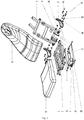
- Fig. 2 illustrates an embodiment of a backrest movement mechanism according to the present invention, which includes an upper frame 1 and a backrest frame 2, and further includes a backrest connecting mechanism 3, wherein the backrest connecting mechanism 3 includes the movement track in conformity with the second arc, and the backrest frame 2 is movably connected to the upper frame 1 via the backrest connecting mechanism 3 and moves along the movement track relative to the upper frame 1.
- the movement track is a long hole approximately in conformity with the second arc.
- the backrest frame 2 is provided with a pin shaft matched with the long hole on the backrest connecting mechanism 3, and the movement of the backrest frame 2 is limited in a movement track limited by the long hole via the pin shaft.
- the backrest connecting mechanisms 3 are used in pairs, and are respectively arranged on two sides of the upper frame 1.
- the backrest connecting mechanism 3 is also provided with two connecting holes, and the backrest connecting mechanism 3 is fixed on the upper frame 1 via the connecting holes.
- the backrest connecting mechanism 3 is fixed on the upper frame 1 using a hexagon socket head cap screw 33.
- a spring shim 34 is arranged between the hexagon socket head cap screw 33 and the backrest connecting mechanism 3.
- the backrest frame 2 is connected to the upper frame 1 via the backrest connecting mechanism 3, and the backrest frame 2 is limited in the movement track of the backrest connecting mechanisms 3 at two sides using a self-locking nut 31, a sliding bearing 32, and a nylon spacer 35, wherein the sliding bearing 32 may also be replaced by a rolling bearing, a copper bush, etc.
- the backrest movement mechanism further includes a driving link for driving the backrest frame, driving elements such as a backrest motor, a hydraulic cylinder, a gas spring, etc. may be used in the driving link, and the embodiment shown in Fig. 2 is the situation that a backrest motor 4 is used.
- two ends of the backrest motor 4 are rotationally connected to the backrest frame 2 and the upper frame 1 via the connecting plates 6 and 7 respectively.
- the backrest movement mechanism further includes a supporting rod 5, two ends of the supporting rod 5 are rotationally connected to the backrest frame 2 and the upper frame 1 via the connecting plates 6 and 7 respectively. Meanwhile, the supporting rod can also has a certain aided effect to the starting up of the driving link.
- the supporting rod 5 may also be replaced by a gas spring, a draw bar, a spring, and other parts with similar functions.
- one end of the connecting plate 6 is fixedly connected to the backrest frame 2, and the other end is provided with a round hole that is used to rotationally connect one end of the backrest motor 4; and one end of the connecting plate 7 is fixedly connected to the upper frame 1, and the other end is provided with a round hole that is used to rotationally connect the other end of the backrest motor 4.
- the connecting plates are connected to the supporting rod 5 using a supporting rod pin 51 and a cotter pin 52, and similarly, the connecting plates are connected to the backrest motor 4 using a motor pin shaft 41 and the cotter pin.
- the present invention also relates to a seat with comfortable backrest in an adjustment process of the backrest angle.
- a seat cushion 11 and a backrest cushion 21 are included, wherein the seat cushion 11 and the backrest cushion 21 are respectively arranged on the upper frame 1 and the backrest frame 2, and the seat further includes the backrest movement mechanism above.
Landscapes
- Health & Medical Sciences (AREA)
- General Health & Medical Sciences (AREA)
- Dentistry (AREA)
- Nursing (AREA)
- Chairs For Special Purposes, Such As Reclining Chairs (AREA)
- Chair Legs, Seat Parts, And Backrests (AREA)
Applications Claiming Priority (2)
| Application Number | Priority Date | Filing Date | Title |
|---|---|---|---|
| CN201410815833.3A CN104545063B (zh) | 2014-12-23 | 2014-12-23 | 一种靠背运动机构的设计方法及由此获得的靠背运动机构 |
| PCT/CN2015/089567 WO2016101657A1 (zh) | 2014-12-23 | 2015-09-15 | 一种靠背运动机构的设计方法及由此获得的靠背运动机构 |
Publications (2)
| Publication Number | Publication Date |
|---|---|
| EP3238570A1 true EP3238570A1 (de) | 2017-11-01 |
| EP3238570A4 EP3238570A4 (de) | 2018-06-20 |
Family
ID=53062963
Family Applications (1)
| Application Number | Title | Priority Date | Filing Date |
|---|---|---|---|
| EP15871731.4A Withdrawn EP3238570A4 (de) | 2014-12-23 | 2015-09-15 | Verfahren zum entwurf eines rückenlehnenbewegungsmechanismus und damit entworfener rückenlehnenbewegungsmechanismus |
Country Status (3)
| Country | Link |
|---|---|
| EP (1) | EP3238570A4 (de) |
| CN (1) | CN104545063B (de) |
| WO (1) | WO2016101657A1 (de) |
Families Citing this family (4)
| Publication number | Priority date | Publication date | Assignee | Title |
|---|---|---|---|---|
| CN104545063B (zh) * | 2014-12-23 | 2018-03-13 | 广东银狐医疗科技股份有限公司 | 一种靠背运动机构的设计方法及由此获得的靠背运动机构 |
| CN112155354B (zh) * | 2020-10-23 | 2024-09-17 | 广东银狐医疗科技股份有限公司 | 防搓背框架及具有其的椅子、床 |
| CN112089245B (zh) * | 2020-10-23 | 2025-02-14 | 广东银狐医疗科技股份有限公司 | 防搓背靠背装置及具有其的椅子、床 |
| CN112190057B (zh) * | 2020-10-23 | 2024-09-24 | 广东银狐医疗科技股份有限公司 | 防搓背装置及具有其的椅子、床 |
Family Cites Families (12)
| Publication number | Priority date | Publication date | Assignee | Title |
|---|---|---|---|---|
| US4372608A (en) * | 1979-12-06 | 1983-02-08 | Kabushiki Kaisha Morita Seisakusho | Treatment chair |
| JPS6185946A (ja) * | 1984-10-01 | 1986-05-01 | 株式会社 モリタ製作所 | 治療台 |
| CN2113670U (zh) * | 1992-02-14 | 1992-08-26 | 饶光德 | 保健躺沙发 |
| JPH08693A (ja) * | 1994-06-27 | 1996-01-09 | Matsushita Electric Works Ltd | マッサージ機 |
| JP2953581B1 (ja) * | 1998-11-13 | 1999-09-27 | パラマウントベッド株式会社 | ベッドにおける背上げ機構 |
| CN2557014Y (zh) * | 2002-09-18 | 2003-06-25 | 林葵 | 一种座具 |
| CN201045968Y (zh) * | 2007-03-26 | 2008-04-16 | 任重 | 一体变位电脑椅 |
| JP2009195278A (ja) * | 2008-02-19 | 2009-09-03 | Sanyo Electric Co Ltd | リクライニング椅子 |
| CN201675412U (zh) * | 2010-02-11 | 2010-12-22 | 福州德辉家具有限公司 | 一种休闲椅 |
| CN102160716B (zh) * | 2011-02-23 | 2012-12-12 | 厦门蒙发利科技(集团)股份有限公司 | 一种可调节靠背位置的椅架 |
| CN201977234U (zh) * | 2011-04-07 | 2011-09-21 | 曹亮 | 一种可调节多功能折叠躺椅 |
| CN104545063B (zh) * | 2014-12-23 | 2018-03-13 | 广东银狐医疗科技股份有限公司 | 一种靠背运动机构的设计方法及由此获得的靠背运动机构 |
-
2014
- 2014-12-23 CN CN201410815833.3A patent/CN104545063B/zh active Active
-
2015
- 2015-09-15 EP EP15871731.4A patent/EP3238570A4/de not_active Withdrawn
- 2015-09-15 WO PCT/CN2015/089567 patent/WO2016101657A1/zh not_active Ceased
Also Published As
| Publication number | Publication date |
|---|---|
| EP3238570A4 (de) | 2018-06-20 |
| WO2016101657A1 (zh) | 2016-06-30 |
| CN104545063A (zh) | 2015-04-29 |
| CN104545063B (zh) | 2018-03-13 |
Similar Documents
| Publication | Publication Date | Title |
|---|---|---|
| EP3238570A1 (de) | Verfahren zum entwurf eines rückenlehnenbewegungsmechanismus und damit entworfener rückenlehnenbewegungsmechanismus | |
| US9718382B2 (en) | Seat suspension | |
| CN106419272A (zh) | 沙发顶腰机械装置 | |
| US12157403B2 (en) | Adjusting apparatus for achieving lying posture in vehicle seat | |
| CN106820697A (zh) | 一种智能健康椅 | |
| US20100249495A1 (en) | Multiple-width bench with adjustable height and inclination | |
| CN107376230B (zh) | 一种脚蹬式下肢康复床 | |
| CN201403845Y (zh) | 人体工学休闲坐具 | |
| CN201492021U (zh) | 减轻脊椎压力的座椅 | |
| WO2014046100A1 (ja) | シェイプアップ用の椅子 | |
| CN207270145U (zh) | 一种智能健康椅 | |
| CN105476321A (zh) | 一种正姿椅 | |
| CN107668941A (zh) | 一种学生矫正座椅 | |
| CN203290526U (zh) | 一种分段式调节靠垫椅 | |
| CN213849652U (zh) | 一种具有良好支撑效果的座椅靠背 | |
| CN203709564U (zh) | 一种矫姿保健座椅 | |
| CN112690606A (zh) | 一种气囊床垫 | |
| CN209331510U (zh) | 一种方便学生写字和预防学生脊椎变形的转椅 | |
| CN204292601U (zh) | 一种靠背运动机构 | |
| CN103919378B (zh) | 一种电脑专用椅 | |
| CN202698460U (zh) | 带可伸缩腿垫的沙发 | |
| CN204273843U (zh) | 一种靠背连接机构 | |
| CN209377119U (zh) | 一种座椅角度调整装置 | |
| JP3204103U (ja) | 健康椅子 | |
| CN105686432A (zh) | 一种心理咨询用椅子 |
Legal Events
| Date | Code | Title | Description |
|---|---|---|---|
| STAA | Information on the status of an ep patent application or granted ep patent |
Free format text: STATUS: THE INTERNATIONAL PUBLICATION HAS BEEN MADE |
|
| PUAI | Public reference made under article 153(3) epc to a published international application that has entered the european phase |
Free format text: ORIGINAL CODE: 0009012 |
|
| STAA | Information on the status of an ep patent application or granted ep patent |
Free format text: STATUS: REQUEST FOR EXAMINATION WAS MADE |
|
| 17P | Request for examination filed |
Effective date: 20170509 |
|
| AK | Designated contracting states |
Kind code of ref document: A1 Designated state(s): AL AT BE BG CH CY CZ DE DK EE ES FI FR GB GR HR HU IE IS IT LI LT LU LV MC MK MT NL NO PL PT RO RS SE SI SK SM TR |
|
| AX | Request for extension of the european patent |
Extension state: BA ME |
|
| DAV | Request for validation of the european patent (deleted) | ||
| DAX | Request for extension of the european patent (deleted) | ||
| A4 | Supplementary search report drawn up and despatched |
Effective date: 20180523 |
|
| RIC1 | Information provided on ipc code assigned before grant |
Ipc: A47C 1/024 20060101AFI20180515BHEP Ipc: A47C 7/40 20060101ALI20180515BHEP |
|
| STAA | Information on the status of an ep patent application or granted ep patent |
Free format text: STATUS: EXAMINATION IS IN PROGRESS |
|
| RIN1 | Information on inventor provided before grant (corrected) |
Inventor name: HE, PENG Inventor name: GUAN, MINGWANG |
|
| 17Q | First examination report despatched |
Effective date: 20190910 |
|
| STAA | Information on the status of an ep patent application or granted ep patent |
Free format text: STATUS: THE APPLICATION IS DEEMED TO BE WITHDRAWN |
|
| 18D | Application deemed to be withdrawn |
Effective date: 20200623 |