EP3238657A1 - Emballage en résine synthétique - Google Patents
Emballage en résine synthétique Download PDFInfo
- Publication number
- EP3238657A1 EP3238657A1 EP15872974.9A EP15872974A EP3238657A1 EP 3238657 A1 EP3238657 A1 EP 3238657A1 EP 15872974 A EP15872974 A EP 15872974A EP 3238657 A1 EP3238657 A1 EP 3238657A1
- Authority
- EP
- European Patent Office
- Prior art keywords
- pouch
- housing section
- package
- synthetic resin
- insertion section
- Prior art date
- Legal status (The legal status is an assumption and is not a legal conclusion. Google has not performed a legal analysis and makes no representation as to the accuracy of the status listed.)
- Withdrawn
Links
Images



Classifications
-
- B—PERFORMING OPERATIONS; TRANSPORTING
- B65—CONVEYING; PACKING; STORING; HANDLING THIN OR FILAMENTARY MATERIAL
- B65D—CONTAINERS FOR STORAGE OR TRANSPORT OF ARTICLES OR MATERIALS, e.g. BAGS, BARRELS, BOTTLES, BOXES, CANS, CARTONS, CRATES, DRUMS, JARS, TANKS, HOPPERS, FORWARDING CONTAINERS; ACCESSORIES, CLOSURES, OR FITTINGS THEREFOR; PACKAGING ELEMENTS; PACKAGES
- B65D77/00—Packages formed by enclosing articles or materials in preformed containers, e.g. boxes, cartons, sacks or bags
- B65D77/04—Articles or materials enclosed in two or more containers disposed one within another
-
- A—HUMAN NECESSITIES
- A61—MEDICAL OR VETERINARY SCIENCE; HYGIENE
- A61C—DENTISTRY; APPARATUS OR METHODS FOR ORAL OR DENTAL HYGIENE
- A61C19/00—Dental auxiliary appliances
- A61C19/06—Implements for therapeutic treatment
-
- A—HUMAN NECESSITIES
- A61—MEDICAL OR VETERINARY SCIENCE; HYGIENE
- A61C—DENTISTRY; APPARATUS OR METHODS FOR ORAL OR DENTAL HYGIENE
- A61C5/00—Filling or capping teeth
- A61C5/60—Devices specially adapted for pressing or mixing capping or filling materials, e.g. amalgam presses
-
- A—HUMAN NECESSITIES
- A61—MEDICAL OR VETERINARY SCIENCE; HYGIENE
- A61J—CONTAINERS SPECIALLY ADAPTED FOR MEDICAL OR PHARMACEUTICAL PURPOSES; DEVICES OR METHODS SPECIALLY ADAPTED FOR BRINGING PHARMACEUTICAL PRODUCTS INTO PARTICULAR PHYSICAL OR ADMINISTERING FORMS; DEVICES FOR ADMINISTERING FOOD OR MEDICINES ORALLY; BABY COMFORTERS; DEVICES FOR RECEIVING SPITTLE
- A61J1/00—Containers specially adapted for medical or pharmaceutical purposes
- A61J1/05—Containers specially adapted for medical or pharmaceutical purposes for collecting, storing or administering blood, plasma or medical fluids ; Infusion or perfusion containers
-
- B—PERFORMING OPERATIONS; TRANSPORTING
- B65—CONVEYING; PACKING; STORING; HANDLING THIN OR FILAMENTARY MATERIAL
- B65D—CONTAINERS FOR STORAGE OR TRANSPORT OF ARTICLES OR MATERIALS, e.g. BAGS, BARRELS, BOTTLES, BOXES, CANS, CARTONS, CRATES, DRUMS, JARS, TANKS, HOPPERS, FORWARDING CONTAINERS; ACCESSORIES, CLOSURES, OR FITTINGS THEREFOR; PACKAGING ELEMENTS; PACKAGES
- B65D75/00—Packages comprising articles or materials partially or wholly enclosed in strips, sheets, blanks, tubes or webs of flexible sheet material, e.g. in folded wrappers
- B65D75/52—Details
- B65D75/58—Opening or contents-removing devices added or incorporated during package manufacture
-
- B—PERFORMING OPERATIONS; TRANSPORTING
- B65—CONVEYING; PACKING; STORING; HANDLING THIN OR FILAMENTARY MATERIAL
- B65D—CONTAINERS FOR STORAGE OR TRANSPORT OF ARTICLES OR MATERIALS, e.g. BAGS, BARRELS, BOTTLES, BOXES, CANS, CARTONS, CRATES, DRUMS, JARS, TANKS, HOPPERS, FORWARDING CONTAINERS; ACCESSORIES, CLOSURES, OR FITTINGS THEREFOR; PACKAGING ELEMENTS; PACKAGES
- B65D75/00—Packages comprising articles or materials partially or wholly enclosed in strips, sheets, blanks, tubes or webs of flexible sheet material, e.g. in folded wrappers
- B65D75/52—Details
- B65D75/58—Opening or contents-removing devices added or incorporated during package manufacture
- B65D75/5861—Spouts
- B65D75/5866—Integral spouts
-
- B—PERFORMING OPERATIONS; TRANSPORTING
- B65—CONVEYING; PACKING; STORING; HANDLING THIN OR FILAMENTARY MATERIAL
- B65D—CONTAINERS FOR STORAGE OR TRANSPORT OF ARTICLES OR MATERIALS, e.g. BAGS, BARRELS, BOTTLES, BOXES, CANS, CARTONS, CRATES, DRUMS, JARS, TANKS, HOPPERS, FORWARDING CONTAINERS; ACCESSORIES, CLOSURES, OR FITTINGS THEREFOR; PACKAGING ELEMENTS; PACKAGES
- B65D81/00—Containers, packaging elements, or packages, for contents presenting particular transport or storage problems, or adapted to be used for non-packaging purposes after removal of contents
- B65D81/32—Containers, packaging elements, or packages, for contents presenting particular transport or storage problems, or adapted to be used for non-packaging purposes after removal of contents for packaging two or more different materials which must be maintained separate prior to use in admixture
- B65D81/3261—Flexible containers having several compartments
- B65D81/3272—Flexible containers having several compartments formed by arranging one flexible container within another
Definitions
- This invention relates to a synthetic resin package containing at least one pouch which accommodates a dental liquid and which, when pressed, is unsealed at one end edge and allows the dental liquid to be flowed out through the unsealed one end edge.
- a dental liquid such as a dental adhesive liquid or disinfectant liquid
- a pouch or a bag portion accommodating a small amount of the dental liquid in a sealed state, stuck to the leading end of an applicator, and applied to an affected area (i.e., lesion) of a patient.
- Patent Document 1 discloses a package provided with a bag portion (compartment) accommodating a dental liquid, andapocket portion adjacent to the bag portion via a sealed portion (break zone).
- the pocket portion houses the leading end of an applicator.
- the bag portion is pressed to exert pressure on the dental liquid, thereby unsealing the sealed portion.
- the dental liquid accommodated in the bag portion is flowed into the pocket portion, and stuck to the leading end of the applicator.
- the leading end of the applicator is removed from the pocket portion, and applied to the affected area.
- Patent Document 1 JP-A-11-146902
- Patent Document 1 the package disclosed in Patent Document 1 is not easy to use, and poses the following problems: (1) The flowing direction of the dental liquid when flowed into the pocket portion upon pressing of the bag portion is toward the open end of the pocket portion. Thus, the dental liquid, particularly when having a low viscosity, is liable to pass through the pocket portion and flow to the outside. (2) When the pressing of the bag portion is released, the bag portion is elastically restored to its original state. As a result, the dental liquid flowed into the pocket portion tends to be returned to the bag portion. (3) Since the package is formed from an opaque material, the flow of the dental liquid cannot be confirmed visually.
- Amain technical challenge to the invention is to provide a synthetic resin package improved at least partially in the ease of use as compared with the aforementioned package disclosed in Patent Document 1, and containing at least one pouch which accommodates a dental liquid and which, when pressed, is unsealed at one end edge and allows the dental liquid to be flowed out through the unsealed one end edge.
- a package in a unique form namely, a package in a form in which both side edges and a bottom edge thereof are closed throughout; an applicator insertion section and a pouch housing section situated adj acently in a lateral direction are defined; in a top edge thereof, a site corresponding to the pouch housing section is closed at least partially, but a site corresponding to the applicator insertion section is open; and a pouch is positioned within the pouch housing section, with one end edge of the pouch to be unsealed facing downward.
- a synthetic resin package containing at least one pouch which accommodates a dental liquid and which, when pressed, is unsealed at one end edge and allows the dental liquid to be flowed out through the unsealed one end edge, wherein both side edges and a bottom edge of the package are closed throughout, an applicator insertion section and a pouch housing section situated adjacently in a lateral direction are defined in the package and, in a top edge of the package, a site corresponding to the pouch housing section is closed at least partially, while a site corresponding to the applicator insertion section is open, the pouch is positioned within the pouch housing section, with the one end edge facing downward, and when the pouch is pressed via the package, the one end edge of the pouch is unsealed, whereby the dental liquid is flowed out from inside the pouch through the one end edge to a lower part of the pouch housing section, and then flowed to a lower
- the pouch is introduced into the pouch housing section, with at least a part of the other end edge portion of the pouch being interposed between predetermined sites of top edge portions of the package.
- the top edge portions are partly joined together, whereby the site of the top edge corresponding to the pouch housing section is closed, and the other end edge portion of the pouch is confined between the top edge portions of the package, while the one end edge of the pouch is located upwardly away from the bottom edge of the pouch housing section.
- opposing wall surfaces of the package are joined together along the boundary between the pouch housing section and the applicator insertion section, but except for a lower end part of the package, whereby the pouch is restricted to a required position within the pouch housing section, and the one end edge of the pouch is located upwardly away from the bottom edge of the pouch housing section.
- the package be formed by shaping a belt-shaped synthetic resin film or sheet into a tubular form, joining both end edge portions of the tubular form over the entire lengths thereof, joining bottom edge portions of the tubular form over the entire lengths thereof, and joining top edge portions of the tubular form partially, and that before the top edge portions are partially joined, the pouch be introduced into the pouch housing section.
- At least one of the lower part of the pouch housing section and the lower part of the applicator insertion section is desirably transparent or translucent.
- a notch extending downward from the top edge be formed in one wall surface of the applicator insertion section.
- the other wall surface of the applicator insertion section be colored in a color different from the color of the one wall surface of the applicator insertion section. It is also preferred that at least apart of the top edge of the applicator insertion section be inclined gradually upwardly in a direction away from the pouch housing section.
- the bottom edge is closed by joining bottom edge portions of both wall surfaces of the package mutually, and a part in a mutually joined region of the bottom edge portions, which corresponds to the pouch housing section, is inclined gradually upwardly in a direction away from the applicator insertion section.
- a part in the mutually joined region of the bottom edge portions, which corresponds to the applicator insertion section be inclined gradually upwardly in a direction away from the pouch housing section.
- an indication is provided at a predetermined site of pressing on at least one wall surface of the pouch housing section.
- at least two of the pouches are located within the pouch housing section, and liquids flowed out of the at least two pouches are mixed.
- the dental liquid flowed out from the one end edge of the pouch when pressed is flowed toward the closed bottom edge of the package.
- the dental liquid does not flow to the outside accidentally.
- the dental liquid flowed out of the pouch when the pouch is pressed is separated from the bottom edge of the pouch. Even if the pouch is elastically restored to the original state after the pressing of the pouch is released, therefore, the dental liquid flowed out of the pouch is not returned into the pouch.
- the dental liquid which is flowed out from the pouch to the lower part of the pouch housing section and flowed into the lower part of the applicator insertion section, can be visually confirmed to be flowing.
- Fig. 1 shows a preferred embodiment of a synthetic resin package configured according to the present invention.
- a package 2 illustrated here is in the form of a vertically long rectangular thin bag as a whole, and both side edges 4a, 4b and a bottom edge 6 thereof are closed throughout.
- Both side edges 4a and 4b are preferably structured to avoid a situation in which a dental liquid flowing out to a lower part of a pouch housing section 12 ascends to a top edge portion of the package 2 by a capillary phenomenon.
- both side edges 4a and 4b are preferably of a semicircular shape or a semielliptical nearly semicircular shape in a transverse sectional view of the package 2.
- both side edges 4a and 4b may have a structure in which the surfaces constituting both side edges 4a and 4b are separated by a sufficient distance so that the dental liquid does not ascend by a capillary phenomenon (in this case, the package 2 is preferably a resin product processed by injection molding, extrusion or blow molding as will be described in detail later).
- the dental liquid flowing out to the lower part of the pouch housing section 12 is easy to take using a liquid holding portion 34 of an applicator 30 to be detailed later (see Figs. 5 and 6 ), and volatilization of the dental liquid can be suppressed.
- a top edge 8 It is important for a top edge 8 to have a part 8a open, but have a remainder 8b closed at least partly and, in the illustrated embodiment, closed over its entire length.
- an applicator insertion section 10 and a pouch housing section 12 located adjacently in a lateral direction are defined, and the open part 8a of the top edge 8 corresponds to the applicator insertion section 10, while the closed remainder 8b of the top edge 8b corresponds to the pouch housing section 12.
- the package 2 may entirely be opaque, transparent or translucent, but advantageously, at least one of a lower part of the applicator insertion section 10 and a lower part of the pouch housing section 12 is transparent or translucent. Since these lower parts are transparent or translucent, the flowing-out state of the dental liquid can be confirmed.
- the range in which they are transparent or translucent is such that the dental liquid having flowed out can be confirmed in the lower part of the applicator insertion section 10 and the lower part of the pouch housing section 12.
- This range may be either the lower part of the applicator insertion section 10, or the lower part of the pouch housing section 12, but in consideration of the confirmation of the flowing-out state of the dental liquid and the ease of shaping of the package 2, it is preferred that the range be both of the lower part of the applicator insertion section 10 and the lower part of the pouch housing section 12.
- a pouch 14 is housed in the pouch housing section 12 of the package 2.
- a pouch 14 which is called a pillow or a pillow package as illustrated in Fig. 2 , may itself be in a well-known form. It may be formed by shaping a belt-shaped film into a tubular form, joining both end edge portions 16 of the tubular form by heat fusion, and joining a bottom edge portion (one end edge portion) 18 and a top edge portion (other end edge portion) 20 of the tubular form by heat fusion.
- both end edge portions 16 of the belt-shaped film joined together are marked with crossed diagonal lines, and the joined bottom edge portion 18 and the joined top edge portion 20 of the tubular form are similarly marked with crossed diagonal lines.
- a dental liquid 21 is accommodated.
- the belt-shaped film for forming the pouch 14 may be a publicly known film of polyethylene, nylon, polyethylene terephthalate, polypropylene, or aluminum, or a laminated film formed by laminating them.
- a preferred one includes a film having gas barrier properties such as a film of an ethylene-vinyl alcohol copolymer, polyvinylidene chloride, silica or aluminum, because many dental liquidsgenerallycontain volatile components at least as some components.
- a dental liquid often contains a polymerizable monomer and/or a photopolymerization initiator, so that the use of a light shielding film is particularly preferred.
- the pouch 14 comprises a resin film having aluminum vapor deposited thereon (aluminum-deposited film) which has both of gas barrier properties and light shielding properties and further has satisfactory formability.
- the thickness of the belt-shaped film can be selected, as appropriate, depending on the material for the film, but in view of the formability of the film, the preferred thickness is of the order of 25 to 200 ⁇ m.
- the hardness (tensile modulus) of the film is not particularly limited, but 1 MPa to 10 GPa, particularly 1 to 5 GPa, is preferred.
- the joint strength of the bottom edge portion 18 is advantageously decreased in comparison with the joint strength of the top edge portion 20, for example, by changing the pressure welding strength and temperature during sealing, or changing the seal width or the seal shape.
- the seal strength is preferably in the range of 15 to 70 N/15 mm at the top edge portion 20, and is preferably in the range of 1 to 15 N/15 mm at the bottom edge portion 18.
- the joined product of both end edge portions 16 of the film is scarcely pressurized and difficultly breakable, and may thus have such joint strength that its joining is not released.
- the pouch 14 can be formed, with the joint strengths of the bottom edge portion 18 and the top edge portion 20 of the pouch 14 being rendered substantially the same. Then, as will be further detailed later, the top edge portion 20 of the pouch 14 is positioned between the top edge portions of the package 2, and the top edge portions of the package 2 are heat bonded, whereby the joint strength of the top edge portion 20 can be increased.
- the viscosity of the dental liquid accommodated in the pouch 14 is not particularly limited.
- the synthetic resin package of the present invention can be used preferably when a dental liquid having a low viscosity is used.
- the synthetic resin package of the present invention can be used preferably, when a dental liquid having a viscosity at 25°C of 0.0001 to 0.1 Pa ⁇ s, particularly 0.0001 to 0.001 Pa ⁇ s, is used.
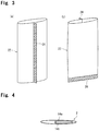
- a belt-shaped synthetic resin film or sheet 22 is shaped into a tubular form, and both-end edge portions 24 are joined together over their entire lengths, preferably, by heat fusion (In Fig. 3a , the tubular form is illustrated, as viewed from the back side, contrary to the views in Fig. 1 and Fig. 3b , in order to clearly illustrate the combined both-end edge portions 24).
- the heat fusion can be performed advantageously by pressing a pair of heating blocks (not shown) against both side surfaces of the film or sheet superposed on each other.
- a bottom edge portion 26 of the tubular form is joined over its entire length. This joining can also be performed advantageously by heat fusion.
- the remainder 28b is joined at least partly, preferably throughout its length, to complete the package 2. The joining of the remainder 28b of the top edge portion is also performed advantageously by heat fusion.
- the sites of joining in the package 2 are marked with crossed diagonal lines.
- the pouch 14 Prior to joining of the remainder 28b of the top edge portion, the pouch 14 is admitted into the pouch housing section 12 of the package 2 through the remainder 28b of the top edge portion, with the bottom edge (one end edge) of the pouch 14 facing downward.
- the top edge portion (other end edge portion) 20 of the pouch 14 is preferably positioned between the remainders 28b of the top edge portion of the tubular form.
- the remainders 28b of the top edge portion of the tubular form are joined together, whereby the top edge portion 20 of the pouch 14 is confined between the remainders 28b of the top edge portion of the package 2, and the pouch 14 is restricted to a predetermined position within the pouch housing section 12.
- the bottom edge of the pouch 14 restricted to the predetermined position is located upwardly away from the bottom edge of the pouch housing section 12, and a predetermined spacing is present between the bottom edge of the pouch housing section 12 and the bottom edge of the pouch 14.
- the top edge portion 20 of the pouch 14 is joined to a required site of the belt-shaped synthetic resin film or sheet (the site defining one wall surface of the remainder 28b of the top edge portion), and then treatments as stated earlier are applied to the belt-shaped synthetic resin film or sheet, whereby the package 2 can be completed.
- the number of the pouches 14 to be housed in the pouch housing section 12 can be changed in accordance with the purpose of use of the dental liquid.
- the number of the pouches 14 to be housed may be one or two or more.
- the number of the pouches 14 is preferably of the order of 1 to 4.
- the dental liquid to be used is a two-pack adhesive liquid, for example, a first pouch 14a accommodating a first adhesive liquid and a second pouch 14b accommodating a second adhesive liquid can be superposed, and introduced into the pouch housing section 12 of the package 2, as shown in Fig.4 .
- the first adhesive discharged from the first pouch 14a and the second adhesive discharged from the second pouch 14b can be effectively mixed within the package 2.
- the synthetic resin film or sheet for use in the production of the package 2 is not particularly limited, and a publicly known synthetic resin film or sheet can be adopted, but one having satisfactory transparency is preferred. If desired, at least one of a lower part of the applicator insertion section 10 and a lower part of the pouch housing section 12 can be rendered transparent or translucent by post-processing.
- the olefin polymers such as polyethylene, polypropylene, polybutylene, and copolymers obtained by copolymerizingtwoor moreolefin monomersselectedfrom ethylene, propylene and butene, are particularly preferred, because their properties such as biological safety, transparency of raw materials, and flexibility are optimal for the uses of the present invention.
- the thickness of the film or sheet constituting the package 2 is not particularly limited, but is preferably of the order of 20 to 500 ⁇ m, particularly 20 to 200 ⁇ m.
- the tensile modulus of the film or sheet is preferably 0.5 to 10 GPa, particularly 1 to 6 GPa, in consideration of the formability and the retention properties of the pouch 14.
- the package 2 can be produced by any of these shaping methods in combination with heat sealing. If such a shaping method is employed, it is preferred, needless to say, that the thickness and the modulus of elasticity of the resin layer constituting the package 2 be the same as those in the ranges illustrated for the synthetic resin film or sheet.
- the package 2 is held, for example, in an upright state by one hand, and the pouch housing section 12 of the package 2 is pinched between the two fingers of the other hand to press the package 2, thereby exerting a pressing force on the pouch 14 via the package 2.
- the joint of the bottom edge portion 18 of the pouch 14 is released, and the bottom edge of the pouch 14 is unsealed.
- the dental liquid accommodated in the pouch 14 is discharged into a lower part of the package 2 through the bottom edge of the pouch 14, and flowed into a lower part of the applicator insertion section 10 of the package 2.
- the dental liquids 21 discharged from the two pouches are effectively mixed and flowed into the lower part of the applicator insertion section 10 from the lower part of the pouch housing section 12 of the package 2.
- the part in the mutually joined region of the bottom edge portion 26 of the package 2 which corresponds to the pouch housing section 12 is inclined gradually upwardly in a direction away from the applicator insertion section 10, whereby the flow of the dental liquid from the lower part of the pouch housing section 12 into the lower part of the applicator insertion section 10 can be promoted.
- the part in the mutually joined region of the bottom edge portion 26 of the package 2, which corresponds to the applicator insertion section 10 is inclined gradually upwardly in a direction away from the pouch housing section 12, as indicated by a dashed double-dotted line 29b in Figs. 1 and 5 ,whereby the accidental discharge of the liquid from the open top edge of the applicator insertion section 10 can be avoided to the maximum extent possible.
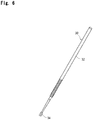
- the applicator 30 is grasped by the other hand, and its leading end part is inserted into the applicator insertion section 10 through the unsealed top edge.
- the applicator 30 well known per se has a slender rod-shaped body 32, and the liquid holding portion 34 disposed at the leading end of the body 32.
- the liquid holding portion 34 can be formed from many hairy pieces.
- the applicator 30 is then pulled out of the applicator insertion section 10, and its liquid holding portion 34 is applied to an affected area (lesion) of a patient, whereby the lesion can be treated with the dental liquid.
- the bottom edge portion 26 is fixed by a common card holder, clip or the like, whereby the applicator 30 can be kept erected and left to stand.
- Fig. 7 shows a modified embodiment of the package 2 configured in accordance with the present invention.
- the opposing wall surfaces of the package 2 are joined together by heat fusion along the boundary between the applicator insertion section 10 and the pouch housing section 12 of the package 2 (in Fig. 7 , a site 36 of heat fusion is marked with crossed diagonal lines), and the cross-sectional area of the pouch housing section 12 is limited to a size approximating the cross-sectional area of the pouch 14.
- the pouch 14 is confined to a required position of the pouch housing section 12, and the bottom edge of the pouch 14 is spaced upwardly from the bottom edge of the pouch housing section 12.
- the top edge of the pouch 14 is located somewhat below the joined top edge portion 28b of the package 2.
- Fig. 8 shows another modified embodiment of the package 2 configured in accordance with the present invention.
- a notch 38 extending downward from the top edge of one side wall (front side wall in Fig. 8 ) is formed in a top edge portion of the applicator insertion section 10 of the package 2.
- the top edge of the site 40 is at the same height as that of the top edge of the closed site 8b ( Fig. 1 ) at the top edge of the package 2, but the top edge of the site 40 can be located at a higher position than the top edge of the site 8b.
- the bottom edge of the notch 38 is located below the above site 8b.
- the bottom edge of the notch 38 can be set to be at substantially the same height as the top edge of the site 8b to position the site 40 above the top edge of the site 8b.
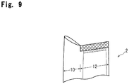
- the top edge of the applicator insertion section 10 in the package 2 can be inclined gradually upwardly in a direction away from the pouch housing section 12. Such an inclination can be formed only in a part of the top edge of the applicator insertion section 10, instead of throughout this top edge as illustrated.
- the embodiment illustrated in Fig. 9 is not markedly difficult to produce itself, but makes it sufficiently easy to recognize the insertion port for the applicator 30.
- a notch extending downward from the top edge of one side wall can be formed in the top edge portion of the applicator insertion section 10 of the package 2.
- an indication 42 showing a site to be pressed is provided at a predetermined site of pressing on one side wall (front side wall in Fig. 8 ) of the pouch housing section 12, namely, the site to be pressed when the liquid accommodated in the pouch 14 is to be discharged.
- the illustrated indication 42 is composed of a regular hexagonal shape colored in a suitable color such as gray, and letters "Push here" provided within the hexagonal shape.
- an indication 42 can be provided on the other side wall (back side wall in Fig. 8 ).
- the packages 2 of the illustrated embodiments are thin bags overall, but the thickness of the lower end part, in particular, of each package can be rendered relatively large to impart a self-supporting form to the package.
Landscapes
- Health & Medical Sciences (AREA)
- Public Health (AREA)
- Veterinary Medicine (AREA)
- Life Sciences & Earth Sciences (AREA)
- Animal Behavior & Ethology (AREA)
- General Health & Medical Sciences (AREA)
- Oral & Maxillofacial Surgery (AREA)
- Dentistry (AREA)
- Epidemiology (AREA)
- Engineering & Computer Science (AREA)
- Mechanical Engineering (AREA)
- Pharmacology & Pharmacy (AREA)
- Hematology (AREA)
- Packages (AREA)
- Medical Preparation Storing Or Oral Administration Devices (AREA)
- Dental Tools And Instruments Or Auxiliary Dental Instruments (AREA)
Applications Claiming Priority (2)
| Application Number | Priority Date | Filing Date | Title |
|---|---|---|---|
| JP2014260051 | 2014-12-24 | ||
| PCT/JP2015/085642 WO2016104406A1 (fr) | 2014-12-24 | 2015-12-21 | Emballage en résine synthétique |
Publications (2)
| Publication Number | Publication Date |
|---|---|
| EP3238657A1 true EP3238657A1 (fr) | 2017-11-01 |
| EP3238657A4 EP3238657A4 (fr) | 2018-07-11 |
Family
ID=56150425
Family Applications (1)
| Application Number | Title | Priority Date | Filing Date |
|---|---|---|---|
| EP15872974.9A Withdrawn EP3238657A4 (fr) | 2014-12-24 | 2015-12-21 | Emballage en résine synthétique |
Country Status (5)
| Country | Link |
|---|---|
| US (1) | US20170340423A1 (fr) |
| EP (1) | EP3238657A4 (fr) |
| JP (1) | JP6723928B2 (fr) |
| CN (1) | CN106999269A (fr) |
| WO (1) | WO2016104406A1 (fr) |
Cited By (1)
| Publication number | Priority date | Publication date | Assignee | Title |
|---|---|---|---|---|
| EP4055098A4 (fr) * | 2019-11-06 | 2023-12-27 | Bridgestone Americas Tire Operations, LLC | Pneu présentant une bande de roulement d'une composition de caoutchouc spécifiée et procédés associés |
Families Citing this family (6)
| Publication number | Priority date | Publication date | Assignee | Title |
|---|---|---|---|---|
| JP7096670B2 (ja) * | 2018-01-16 | 2022-07-06 | 白元アース株式会社 | 二重袋および二重袋の使用方法 |
| EP3919041B1 (fr) | 2019-01-31 | 2023-07-19 | Tokuyama Dental Corporation | Emballage d'agent liquide composite et procédé de fabrication de ce dernier, et kit destiné à préparer une composition liquide à constituants multiples utilisant l'emballage d'agent liquide composite et procédé de fabrication de ce dernier |
| KR102289080B1 (ko) * | 2020-01-13 | 2021-08-12 | 주식회사 이엠코퍼레이션 | 이종 물품이 포장된 스틱 파우치 |
| JP7479628B2 (ja) | 2020-06-19 | 2024-05-09 | 株式会社トクヤマデンタル | 2液型歯科用接着性組成物 |
| US20240002136A1 (en) * | 2020-12-21 | 2024-01-04 | 3M Innovative Properties Company | Device for storing and dispensing flowable compositions |
| JP7625261B2 (ja) * | 2021-05-27 | 2025-02-03 | 株式会社トクヤマデンタル | 多成分系液状組成物調製キット用補助器具 |
Family Cites Families (20)
| Publication number | Priority date | Publication date | Assignee | Title |
|---|---|---|---|---|
| US1345243A (en) * | 1920-06-29 | riedy | ||
| US2928353A (en) * | 1955-12-19 | 1960-03-15 | Jerome L Murray | Fluid pressure devices |
| US3724651A (en) * | 1971-03-03 | 1973-04-03 | Johnson & Johnson | Peelable surgical package |
| US4411662A (en) * | 1982-04-06 | 1983-10-25 | Baxter Travenol Laboratories, Inc. | Sterile coupling |
| JPS58156664U (ja) * | 1982-04-14 | 1983-10-19 | 株式会社昭和丸筒 | 吸収材料等の包装用シ−ル袋 |
| JPH0532116Y2 (fr) * | 1989-05-24 | 1993-08-18 | ||
| CA2086659C (fr) * | 1992-01-15 | 1999-01-12 | Paul H. Hanifl | Systeme pour impregner et distribuer un ecouvillon |
| US5346061A (en) * | 1992-08-06 | 1994-09-13 | Avitar, Inc. | Biostable treatment delivery system |
| JP3872860B2 (ja) * | 1997-03-11 | 2007-01-24 | 積水化学工業株式会社 | 薬液吸収材容器 |
| JP2000281144A (ja) * | 1999-03-26 | 2000-10-10 | Terumo Corp | 包装体 |
| JP4298875B2 (ja) * | 1999-11-10 | 2009-07-22 | テルモ株式会社 | 包装体 |
| US8016877B2 (en) * | 1999-11-17 | 2011-09-13 | Medtronic Corevalve Llc | Prosthetic valve for transluminal delivery |
| JP4642277B2 (ja) * | 2001-06-21 | 2011-03-02 | 株式会社ジーシー | 唾液の前処理用具及び唾液の前処理方法 |
| JP3966755B2 (ja) * | 2002-04-03 | 2007-08-29 | 白十字株式会社 | 衛生材料容器 |
| US20080027141A1 (en) * | 2006-07-05 | 2008-01-31 | Kaohsiung Medical University | 1,3-Dihydroxyl-9,10-anthraquinone and 3-[(3-amino)-propoxy]- 9,10-anthraquinone derivatives and pharmaceutical compositions comprising the same |
| JP2008037097A (ja) * | 2006-07-10 | 2008-02-21 | Seiko Epson Corp | 液体供給システム及び液体消費装置 |
| CN200957908Y (zh) * | 2006-10-18 | 2007-10-10 | 上海埃蒙迪材料科技有限公司 | 牙弓丝包装袋 |
| FR2928353B1 (fr) * | 2008-03-06 | 2012-10-26 | Smac Sarl | Dispositif de conditionnement sous forme de sachet bicompartiment. |
| US8302776B2 (en) * | 2009-12-30 | 2012-11-06 | Kimberly-Clark Worldwide, Inc. | Pack of oral care items |
| WO2012136724A1 (fr) * | 2011-04-06 | 2012-10-11 | Basf Se | Composés pyrimidinium substitués utilisables dans le cadre de la lutte contre les animaux nuisibles |
-
2015
- 2015-12-21 EP EP15872974.9A patent/EP3238657A4/fr not_active Withdrawn
- 2015-12-21 CN CN201580066605.3A patent/CN106999269A/zh active Pending
- 2015-12-21 JP JP2016566336A patent/JP6723928B2/ja active Active
- 2015-12-21 WO PCT/JP2015/085642 patent/WO2016104406A1/fr not_active Ceased
- 2015-12-21 US US15/538,540 patent/US20170340423A1/en not_active Abandoned
Cited By (1)
| Publication number | Priority date | Publication date | Assignee | Title |
|---|---|---|---|---|
| EP4055098A4 (fr) * | 2019-11-06 | 2023-12-27 | Bridgestone Americas Tire Operations, LLC | Pneu présentant une bande de roulement d'une composition de caoutchouc spécifiée et procédés associés |
Also Published As
| Publication number | Publication date |
|---|---|
| EP3238657A4 (fr) | 2018-07-11 |
| CN106999269A (zh) | 2017-08-01 |
| JP6723928B2 (ja) | 2020-07-15 |
| JPWO2016104406A1 (ja) | 2017-10-05 |
| WO2016104406A1 (fr) | 2016-06-30 |
| US20170340423A1 (en) | 2017-11-30 |
Similar Documents
| Publication | Publication Date | Title |
|---|---|---|
| EP3238657A1 (fr) | Emballage en résine synthétique | |
| US9950842B2 (en) | Multiple zipper slider bag | |
| JP5431051B2 (ja) | 微少容量の注射器用ピストン及び該ピストンを取り付けたプランジャー | |
| CN206965753U (zh) | 一种具有试剂存储单元的微流控芯片 | |
| CA2763224C (fr) | Emballage-coque avec parois laterales a inclinaison | |
| EP1394071A4 (fr) | Contenant a deux compartiments | |
| US20190185239A1 (en) | Easy peel pouch | |
| US20240269038A1 (en) | Primary Packaging | |
| JP2020055646A (ja) | 薬剤包装用ptpシート | |
| KR20220113801A (ko) | 약물 전달 장치를 위한 패키징 시스템 및 패키징 키트 | |
| JP4883600B2 (ja) | スパウト | |
| JP2011126585A (ja) | 折曲げ開封用包装容器 | |
| US12329719B2 (en) | Administration packaging and method for its production | |
| JP4749057B2 (ja) | 複室輸液容器及びその製造方法 | |
| JP4675502B2 (ja) | 液体収容バッグ | |
| JP7298934B2 (ja) | 複合液剤包装体及びその製造方法、並びに前記複合液剤包装体を用いた多成分系液状組成物調製用キット及びその製造方法 | |
| JP5133849B2 (ja) | 医療用複室容器 | |
| JP6710084B2 (ja) | 液体バッグおよび液体バッグの製造方法 | |
| US20240109240A1 (en) | Administration packaging, production apparatus and production method | |
| JP6375189B2 (ja) | 合成樹脂製容器 | |
| RU2772399C1 (ru) | Упаковка композитного жидкого средства и способ ее изготовления, а также набор для изготовления многокомпонентной жидкой композиции с применением упаковки композитного жидкого средства и способ его изготовления | |
| JP4797718B2 (ja) | 異種材料を一体化した栓 | |
| JP2010269132A (ja) | 医療用容器 | |
| KR20050078405A (ko) | 에틸렌 비닐 아세테이트를 이용한 진공포장용 필름 및 이필름의 제조방법 | |
| JP2014176732A (ja) | 医療用容器の製造方法および医療用容器 |
Legal Events
| Date | Code | Title | Description |
|---|---|---|---|
| STAA | Information on the status of an ep patent application or granted ep patent |
Free format text: STATUS: THE INTERNATIONAL PUBLICATION HAS BEEN MADE |
|
| PUAI | Public reference made under article 153(3) epc to a published international application that has entered the european phase |
Free format text: ORIGINAL CODE: 0009012 |
|
| STAA | Information on the status of an ep patent application or granted ep patent |
Free format text: STATUS: REQUEST FOR EXAMINATION WAS MADE |
|
| 17P | Request for examination filed |
Effective date: 20170518 |
|
| AK | Designated contracting states |
Kind code of ref document: A1 Designated state(s): AL AT BE BG CH CY CZ DE DK EE ES FI FR GB GR HR HU IE IS IT LI LT LU LV MC MK MT NL NO PL PT RO RS SE SI SK SM TR |
|
| AX | Request for extension of the european patent |
Extension state: BA ME |
|
| DAV | Request for validation of the european patent (deleted) | ||
| DAX | Request for extension of the european patent (deleted) | ||
| A4 | Supplementary search report drawn up and despatched |
Effective date: 20180611 |
|
| RIC1 | Information provided on ipc code assigned before grant |
Ipc: B65D 81/32 20060101ALN20180605BHEP Ipc: A61J 1/05 20060101ALN20180605BHEP Ipc: A61C 19/06 20060101ALN20180605BHEP Ipc: A61C 5/60 20170101ALN20180605BHEP Ipc: B65D 77/04 20060101AFI20180605BHEP |
|
| STAA | Information on the status of an ep patent application or granted ep patent |
Free format text: STATUS: EXAMINATION IS IN PROGRESS |
|
| 17Q | First examination report despatched |
Effective date: 20190424 |
|
| STAA | Information on the status of an ep patent application or granted ep patent |
Free format text: STATUS: THE APPLICATION HAS BEEN WITHDRAWN |
|
| 18W | Application withdrawn |
Effective date: 20190523 |