EP3238765B1 - Vorrichtungen zum ermitteln eines füllvolumens eines extrakorporalen blutkreislaufs - Google Patents
Vorrichtungen zum ermitteln eines füllvolumens eines extrakorporalen blutkreislaufs Download PDFInfo
- Publication number
- EP3238765B1 EP3238765B1 EP17172308.3A EP17172308A EP3238765B1 EP 3238765 B1 EP3238765 B1 EP 3238765B1 EP 17172308 A EP17172308 A EP 17172308A EP 3238765 B1 EP3238765 B1 EP 3238765B1
- Authority
- EP
- European Patent Office
- Prior art keywords
- fluid
- blood circuit
- extracorporeal blood
- control
- regulating device
- Prior art date
- Legal status (The legal status is an assumption and is not a legal conclusion. Google has not performed a legal analysis and makes no representation as to the accuracy of the status listed.)
- Active
Links
Images


Classifications
-
- A—HUMAN NECESSITIES
- A61—MEDICAL OR VETERINARY SCIENCE; HYGIENE
- A61M—DEVICES FOR INTRODUCING MEDIA INTO, OR ONTO, THE BODY; DEVICES FOR TRANSDUCING BODY MEDIA OR FOR TAKING MEDIA FROM THE BODY; DEVICES FOR PRODUCING OR ENDING SLEEP OR STUPOR
- A61M1/00—Suction or pumping devices for medical purposes; Devices for carrying-off, for treatment of, or for carrying-over, body-liquids; Drainage systems
- A61M1/36—Other treatment of blood in a by-pass of the natural circulatory system, e.g. temperature adaptation, irradiation ; Extra-corporeal blood circuits
- A61M1/3621—Extra-corporeal blood circuits
- A61M1/3643—Priming, rinsing before or after use
-
- A—HUMAN NECESSITIES
- A61—MEDICAL OR VETERINARY SCIENCE; HYGIENE
- A61M—DEVICES FOR INTRODUCING MEDIA INTO, OR ONTO, THE BODY; DEVICES FOR TRANSDUCING BODY MEDIA OR FOR TAKING MEDIA FROM THE BODY; DEVICES FOR PRODUCING OR ENDING SLEEP OR STUPOR
- A61M1/00—Suction or pumping devices for medical purposes; Devices for carrying-off, for treatment of, or for carrying-over, body-liquids; Drainage systems
- A61M1/36—Other treatment of blood in a by-pass of the natural circulatory system, e.g. temperature adaptation, irradiation ; Extra-corporeal blood circuits
- A61M1/3621—Extra-corporeal blood circuits
- A61M1/3622—Extra-corporeal blood circuits with a cassette forming partially or totally the blood circuit
- A61M1/36225—Extra-corporeal blood circuits with a cassette forming partially or totally the blood circuit with blood pumping means or components thereof
-
- A—HUMAN NECESSITIES
- A61—MEDICAL OR VETERINARY SCIENCE; HYGIENE
- A61M—DEVICES FOR INTRODUCING MEDIA INTO, OR ONTO, THE BODY; DEVICES FOR TRANSDUCING BODY MEDIA OR FOR TAKING MEDIA FROM THE BODY; DEVICES FOR PRODUCING OR ENDING SLEEP OR STUPOR
- A61M1/00—Suction or pumping devices for medical purposes; Devices for carrying-off, for treatment of, or for carrying-over, body-liquids; Drainage systems
- A61M1/36—Other treatment of blood in a by-pass of the natural circulatory system, e.g. temperature adaptation, irradiation ; Extra-corporeal blood circuits
- A61M1/3621—Extra-corporeal blood circuits
- A61M1/3622—Extra-corporeal blood circuits with a cassette forming partially or totally the blood circuit
- A61M1/36226—Constructional details of cassettes, e.g. specific details on material or shape
- A61M1/362262—Details of incorporated reservoirs
-
- A—HUMAN NECESSITIES
- A61—MEDICAL OR VETERINARY SCIENCE; HYGIENE
- A61M—DEVICES FOR INTRODUCING MEDIA INTO, OR ONTO, THE BODY; DEVICES FOR TRANSDUCING BODY MEDIA OR FOR TAKING MEDIA FROM THE BODY; DEVICES FOR PRODUCING OR ENDING SLEEP OR STUPOR
- A61M1/00—Suction or pumping devices for medical purposes; Devices for carrying-off, for treatment of, or for carrying-over, body-liquids; Drainage systems
- A61M1/36—Other treatment of blood in a by-pass of the natural circulatory system, e.g. temperature adaptation, irradiation ; Extra-corporeal blood circuits
- A61M1/3621—Extra-corporeal blood circuits
- A61M1/3643—Priming, rinsing before or after use
- A61M1/3644—Mode of operation
-
- A—HUMAN NECESSITIES
- A61—MEDICAL OR VETERINARY SCIENCE; HYGIENE
- A61M—DEVICES FOR INTRODUCING MEDIA INTO, OR ONTO, THE BODY; DEVICES FOR TRANSDUCING BODY MEDIA OR FOR TAKING MEDIA FROM THE BODY; DEVICES FOR PRODUCING OR ENDING SLEEP OR STUPOR
- A61M1/00—Suction or pumping devices for medical purposes; Devices for carrying-off, for treatment of, or for carrying-over, body-liquids; Drainage systems
- A61M1/36—Other treatment of blood in a by-pass of the natural circulatory system, e.g. temperature adaptation, irradiation ; Extra-corporeal blood circuits
- A61M1/3606—Arrangements for blood-volume reduction of extra-corporeal circuits
-
- A—HUMAN NECESSITIES
- A61—MEDICAL OR VETERINARY SCIENCE; HYGIENE
- A61M—DEVICES FOR INTRODUCING MEDIA INTO, OR ONTO, THE BODY; DEVICES FOR TRANSDUCING BODY MEDIA OR FOR TAKING MEDIA FROM THE BODY; DEVICES FOR PRODUCING OR ENDING SLEEP OR STUPOR
- A61M1/00—Suction or pumping devices for medical purposes; Devices for carrying-off, for treatment of, or for carrying-over, body-liquids; Drainage systems
- A61M1/36—Other treatment of blood in a by-pass of the natural circulatory system, e.g. temperature adaptation, irradiation ; Extra-corporeal blood circuits
- A61M1/3621—Extra-corporeal blood circuits
- A61M1/3622—Extra-corporeal blood circuits with a cassette forming partially or totally the blood circuit
- A61M1/36226—Constructional details of cassettes, e.g. specific details on material or shape
- A61M1/362265—Details of valves
-
- A—HUMAN NECESSITIES
- A61—MEDICAL OR VETERINARY SCIENCE; HYGIENE
- A61M—DEVICES FOR INTRODUCING MEDIA INTO, OR ONTO, THE BODY; DEVICES FOR TRANSDUCING BODY MEDIA OR FOR TAKING MEDIA FROM THE BODY; DEVICES FOR PRODUCING OR ENDING SLEEP OR STUPOR
- A61M2205/00—General characteristics of the apparatus
- A61M2205/33—Controlling, regulating or measuring
- A61M2205/3306—Optical measuring means
-
- A—HUMAN NECESSITIES
- A61—MEDICAL OR VETERINARY SCIENCE; HYGIENE
- A61M—DEVICES FOR INTRODUCING MEDIA INTO, OR ONTO, THE BODY; DEVICES FOR TRANSDUCING BODY MEDIA OR FOR TAKING MEDIA FROM THE BODY; DEVICES FOR PRODUCING OR ENDING SLEEP OR STUPOR
- A61M2205/00—General characteristics of the apparatus
- A61M2205/33—Controlling, regulating or measuring
- A61M2205/3368—Temperature
-
- A—HUMAN NECESSITIES
- A61—MEDICAL OR VETERINARY SCIENCE; HYGIENE
- A61M—DEVICES FOR INTRODUCING MEDIA INTO, OR ONTO, THE BODY; DEVICES FOR TRANSDUCING BODY MEDIA OR FOR TAKING MEDIA FROM THE BODY; DEVICES FOR PRODUCING OR ENDING SLEEP OR STUPOR
- A61M2205/00—General characteristics of the apparatus
- A61M2205/33—Controlling, regulating or measuring
- A61M2205/3375—Acoustical, e.g. ultrasonic, measuring means
-
- A—HUMAN NECESSITIES
- A61—MEDICAL OR VETERINARY SCIENCE; HYGIENE
- A61M—DEVICES FOR INTRODUCING MEDIA INTO, OR ONTO, THE BODY; DEVICES FOR TRANSDUCING BODY MEDIA OR FOR TAKING MEDIA FROM THE BODY; DEVICES FOR PRODUCING OR ENDING SLEEP OR STUPOR
- A61M2205/00—General characteristics of the apparatus
- A61M2205/33—Controlling, regulating or measuring
- A61M2205/3379—Masses, volumes, levels of fluids in reservoirs, flow rates
-
- A—HUMAN NECESSITIES
- A61—MEDICAL OR VETERINARY SCIENCE; HYGIENE
- A61M—DEVICES FOR INTRODUCING MEDIA INTO, OR ONTO, THE BODY; DEVICES FOR TRANSDUCING BODY MEDIA OR FOR TAKING MEDIA FROM THE BODY; DEVICES FOR PRODUCING OR ENDING SLEEP OR STUPOR
- A61M2205/00—General characteristics of the apparatus
- A61M2205/33—Controlling, regulating or measuring
- A61M2205/3379—Masses, volumes, levels of fluids in reservoirs, flow rates
- A61M2205/3393—Masses, volumes, levels of fluids in reservoirs, flow rates by weighing the reservoir
-
- Y—GENERAL TAGGING OF NEW TECHNOLOGICAL DEVELOPMENTS; GENERAL TAGGING OF CROSS-SECTIONAL TECHNOLOGIES SPANNING OVER SEVERAL SECTIONS OF THE IPC; TECHNICAL SUBJECTS COVERED BY FORMER USPC CROSS-REFERENCE ART COLLECTIONS [XRACs] AND DIGESTS
- Y10—TECHNICAL SUBJECTS COVERED BY FORMER USPC
- Y10T—TECHNICAL SUBJECTS COVERED BY FORMER US CLASSIFICATION
- Y10T137/00—Fluid handling
- Y10T137/0318—Processes
Definitions
- the present invention relates to a control or regulation device according to claim 1 and a treatment device according to claim 18.
- extracorporeal blood circuits undergo preparation prior to their use in a medical treatment procedure.
- the treatment device used for treatment with the extracorporeal blood circuit is adapted to the upcoming treatment modality and/or to the (disposable) items used, such as blood circuit or blood filter, before the start of treatment.
- the extracorporeal blood circuit is usually filled with a fluid (for example a substituate solution) before it is used and flushed with it in order to remove any production residues and/or air bubbles from the extracorporeal blood circuit;
- a fluid for example a substituate solution
- the treatment device it is occasionally set which treatment modality should or may be used for treatment, or what type or size the blood filter or blood circuit used is. Both to determine a minimum flushing volume for the blood circuit and to set the Treatment device on the (disposable) items used, it is necessary to know at least one parameter about this.
- EP0416808 A1 discloses an apparatus for measuring flow in a conduit.
- WO2010/133319 discloses a device and a method for identifying a tubing system for an extracorporeal blood treatment device.
- One object of the present invention is to specify a control or regulation device and a treatment device with which the disclosed method for, preferably automatically, determining at least one parameter of an extracorporeal blood circuit can be carried out.
- control or regulation device with the features of claim 1. It is also provided by a treatment device with the features of claim 18
- an extracorporeal blood circuit has a medical functional device.
- This functional device can, for example, have or consist of a blood cassette (in particular designed as a disposable) and/or a treatment device, such as a dialyzer or a blood filter, and/or a blood tubing set.
- the size of the volume (also in short: the volume) is a numerical value with a dimension (such as ml; milliliters) or without a dimension. In other embodiments according to the invention, this is understood to mean a classification of the volume or its assignment to specific volume classes.
- filling refers to the introduction or filling in of—particularly medical—fluid, e.g. B. Substituate and / or dialysis fluid, in the extracorporeal blood circuit.
- the filling takes place once and/or initially, ie before the start of the treatment of the patient, for example a blood treatment procedure, e.g. B. dialysis (hemodialysis, hemofiltration, hemodiafiltration or the like) and / or before the start of the flushing process.
- the filling within the meaning of the present invention is started, has taken place or is completed before the start of the flushing process.
- the extracorporeal blood circuit is completely or essentially completely filled with fluid during filling.
- so much fluid is introduced into the extracorporeal blood circuit that the volume introduced corresponds to an internal volume or a maximum (absorption) volume of the extracorporeal blood circuit (with or without components in fluid connection therewith, such as a blood filter or a blood cassette).
- the extracorporeal blood circuit does not have to be completely filled with fluid in some embodiments according to the invention.
- the extracorporeal blood circuit is only partially, e.g. up to a certain point, e.g. B. a detection device arranged in or on the extracorporeal blood circuit, used to detect a fluid or to detect a change between different fluids, filled with fluid.
- a detection device arranged in or on the extracorporeal blood circuit, used to detect a fluid or to detect a change between different fluids, filled with fluid.
- provision can be made, for example, for the (filling) volume or total volume or total internal volume or capacity of the extracorporeal blood circuit to be extrapolated or estimated.
- This Extrapolation or estimation is based on the size of the detected volume (e.g. this is the filled portion of the extracorporeal blood circuit between the fluid introduction site and the detection site) and on knowing the remaining part of the total extracorporeal blood circuit.
- the fluid introduced into the extracorporeal blood circuit is a priming and/or rinsing liquid, for example a substituate liquid.
- the method includes further processing of the detected size of the volume of the fluid.
- the further processing serves to obtain the at least one parameter of the extracorporeal blood circuit.
- the further processing of the detected variable is or includes making a statement about the parameter.
- the further processing of the detected size of the volume is or includes a conversion of the value of the volume using algorithms, functions or relationships in order to obtain the parameter. They can be stored in a storage device, e.g. B. a memory or control device of a treatment device, be or will be stored.
- the further processing of the detected size of the volume is or is included in some embodiments according to the invention communicating the obtained parameter to a supervisor, but not in other embodiments.
- the further processing of the detected size of the volume is or includes a comparison of the detected volume with sizes or information suitable for determining the parameter (for example using a comparison table).
- the further processing of the detected size of the volume is or includes an assignment of a parameter to the extracorporeal blood circuit and/or to individual components thereof based on the detected size of the volume.
- the further processing of the detected size of the volume includes communicating the parameter to a supervisor (for example by means of a display, error message, alarm or the like), in others not.
- a parameter is a piece of information that is characteristic of the extracorporeal blood circuit used, alternatively exclusively (the piece of information or the parameter is clearly assigned only to the extracorporeal blood circuit used or the type of extracorporeal blood circuit used) or not exclusively (the piece of information or the parameter is assigned to other blood circuits or types of extracorporeal blood circuits in addition to the extracorporeal blood circuit used or the type of extracorporeal blood circuits used, but still allows a certain assignment, for example to a closed group of extracorporeal blood circuits).
- the volume of the fluid that is introduced into the extracorporeal blood circuit to fill it is a cumulative volume.
- a cumulative volume designates the total volume of fluid introduced for the first or one-time, in particular for the complete or essentially complete, filling of the extracorporeal blood circuit.
- the cumulative volume thus also includes partial volumes which, in order to achieve the initial filling of the extracorporeal blood circuit, e.g. B. due to a during and due to Filling taking place ventilation of the extracorporeal blood circuit to achieve the desired filling must be replaced or refilled.
- the achievement of the filled state of the extracorporeal blood circuit is detected by means of a detection device for detecting a fluid or a fluid state (such as a color, a mixing ratio, a change in different fluids, such as air being displaced by the fluid, a boundary between a liquid fluid and air, etc.) detected.
- a fluid or a fluid state such as a color, a mixing ratio, a change in different fluids, such as air being displaced by the fluid, a boundary between a liquid fluid and air, etc.
- the detection device is arranged in or on the extracorporeal blood circuit. In some embodiments according to the invention, it has an operative or signal connection with it.
- the detection device is selected from level detectors (e.g. ultrasonic level detectors, capacitive level detectors, optical level detectors or the like), air detectors (e.g. air bubble detectors), venous bubble catchers, or the like, or combinations thereof, which are based on the same physical principle or according to work on different principles.
- level detectors e.g. ultrasonic level detectors, capacitive level detectors, optical level detectors or the like
- air detectors e.g. air bubble detectors
- venous bubble catchers e.g. venous bubble catchers, or the like, or combinations thereof, which are based on the same physical principle or according to work on different principles.
- a transit time of a fluid conveyed by a blood pump into the extracorporeal blood circuit is determined or calculated.
- a predetermined flow can be, for example, a continuously increasing flow or a flow that suddenly increases at predetermined points in time with a known jump height.
- the time at which the fluid occurs is determined at a first sensor of the extracorporeal blood circuit. This point in time is referred to as the first point in time.
- the time at which the fluid occurs is determined at a second sensor of the extracorporeal blood circuit. This point in time is referred to as the second point in time.
- the time difference between the first point in time and the second point in time is determined.
- detecting, determining or calculating the magnitude of the volume of fluid introduced is or includes a multiplication of the time difference by the constant flow rate of the blood pump.
- the volume of the extracorporeal blood circuit can thus be determined based on the transit time of the Fluids, for example blood, are determined from the first sensor to the second sensor when the delivery capacity or quantity of the pump used, here only for example a blood pump, is known.
- the delivery capacity or quantity of the pump can result from a delivery rate of the pump that is known to be constant or otherwise between the first and the second point in time.
- the total volume of the pumped fluid and thus the filling volume taken up jointly by the tube sections and the treatment device can be determined based on the time difference or the running time and the pump rate, power or quantity per time.
- the type of treatment device used e.g. the dialyzer
- each type of treatment device takes up a typical volume for it.
- any of the optical sensors referred to herein may be an optical-based venous blood detector (for detecting blood in the venous leg of the extracorporeal blood circuit), an optical sensor for measuring at least one blood parameter, or any other type of sensor.
- a blood parameter is to be understood as meaning, inter alia, the relative blood volume, the hemoglobin concentration and the hematocrit.
- Other optical detectors that can be used are not designed to measure blood parameters.
- an optical sensor as described above for measuring at least one blood parameter is a device for measurements in blood as described in the published application EP 1 748 292 A1 and/or in the disclosure document WO 2004/057313 A1 is revealed.
- An optical sensor for measuring at least one blood parameter can in particular be a device which has a measuring unit which has a light emitter and a light detector. With this, light with a predetermined wavelength is introduced into a section of the extracorporeal blood circuit, for example into the arterial section. The section is transparent to light, in particular infrared light. Light emerging from the section is received with the light detector. The presence of fluid, for example blood, in the section can be detected by means of the optical sensor for measuring at least one blood parameter. This can be done, for example, using the ratio between the intensity of the incoming light and the intensity of the outgoing light.
- the optical sensor is designed to measure at least one blood parameter in order to measure other blood parameters such as relative blood volume, hemoglobin concentration, hematocrit.
- the control device is configured or set up accordingly.
- certain embodiments according to the invention provide for the use of light with a wavelength of 790 to 820 nm, preferably 800 to 810 nm and particularly preferably 805 nm.
- the light emitter and the light detector are arranged at a section of the extracorporeal blood circuit for a measurement in this section or through this section which lies between the patient's arterial needle and the blood pump.
- this section is stiffer (also referred to herein as more stably guided or contained) than at least one other section of the extracorporeal blood circuit, than a section arranged downstream of the blood pump, or than all other sections of the extracorporeal blood circuit.
- the stiffer section is a section which is surrounded at least partially on its exterior or circumference by a boundary or collar (hereinafter: collar for short).
- the cuff exerts pressure on the section guided through it, for example in such a way that the section inside the cuff has a different cross-sectional profile than in front of and/or behind the cuff. For this reason it can be described as stiff(er).
- the inherently round or circular cross-section of the blood tubing in the cuff can be shaped into a more angular or square cross-section, or a cross-section with at least one or two straight sides.
- An example of such a cuff or the idea on which it is based is in the above-mentioned disclosures EP 1 748 292 A1 and WO 2004/057313 A1 disclosed, see for example Figs. 1 to 5 there.
- pressing the blood tube through the cuff can bring about a predetermined pressure and/or a predetermined change in shape or cross section.
- the blood tubing section can thus be compressed or compressed in a defined manner.
- the cuff can be designed as an elongate container.
- the cuff can be designed with receptacles or openings for light emitters and/or light detectors.
- Both the first sensor and the second sensor can be designed independently of one another as sensors which determine the presence of fluid by measuring the optical density, ultrasonic measurement, acoustic measurement or temperature measurement.
- the determined time difference is used for the purpose of process control of the blood treatment or for dismantling the blood treatment device after the treatment has ended.
- knowledge of the time difference can be used to automatically stop the reinfusion of blood after the end of the treatment.
- the detection device is intended to detect a fluid-air boundary. It can thus indicate when the air in the (still unused) extracorporeal blood circuit was displaced upstream of the detection device by the fluid that was filled in and was removed from the extracorporeal blood circuit, for example via a venting device.
- the volume of the fluid is detected via the (number of) rotor rotations of a delivery device, by means of which the extracorporeal blood circuit was filled.
- the conveying device can be a hose roller pump, for example a hose roller pump, which is used in treatment methods for conveying blood (blood pump) and/or substituate (substituate pump) and/or dialysate.
- the volume of the fluid is determined by decreasing the weight of a source of the fluid, e.g. B. a liquid bag detected.
- the weight loss can be detected, for example, by weighing the liquid bag.
- the disclosed method includes comparing the determined parameter with (detected and stored) parameters of a large number of usable medical functional devices for identifying or assigning the extracorporeal blood circuit of a medical functional device or component present or used therein. Such a comparison, in some embodiments of the present invention, corresponds to or includes the further processing discussed above.
- the comparison can e.g. B. done by means of a comparison table.
- the method includes comparing the determined parameter with (detected and stored) parameters of a large number of treatment devices that can be used in order to identify a treatment device that is used.
- the large number of medical functional devices that can be used or the treatment devices that can be used or information about them can be stored in suitable tables.
- preparation that usually takes place before the extracorporeal blood circuit is used for a treatment serves to remove any production residues (caused by the production of the treatment device and/or the blood tubing set) and/or air from the blood circuit or to remove the associated components.
- the to The amount of fluid required for rinsing or priming or the required volume of fluid is usually greater than the amount of fluid required for simply filling the extracorporeal blood circuit or the capacity or volume of fluid.
- a generally applicable minimum volume of e.g. B. 500 ml fixed. This specification is obviously not coordinated, adapted or even optimized for the specific extracorporeal blood tubing set used and its components, such as the blood filter used.
- the disclosed method includes the determination of a minimum, optimal and/or maximum priming or flushing volume for priming or flushing the extracorporeal blood circuit using the determined parameter.
- the priming or rinsing volume is thus advantageously adapted to the extracorporeal blood circuit actually used and its components on the basis of the determined parameter.
- the parameter can be, for example, the filling volume of the blood circuit or its type.
- V_min is the minimum flushing volume in the preparation of the treatment process
- V_Set is the volume of the medical facility, specifically one blood tubing set or blood tubing sets
- V_Dial is the volume of the treatment device, in particular a dialyzer or blood filter
- a and b are each numbers or constants.
- a is any number, which can assume values from 1 to 3 in particular.
- b is any number, which can assume values from 2 to 5 in particular.
- further factors such as (treatment) instructions or the like can be included in the determination of the priming or flushing volume.
- the method includes determining or influencing a control of the (subsequent) treatment method with the inclusion or as a function of the determined parameter.
- the disclosed method includes the definition of maximum and/or minimum pump rates, an (automatic) definition of reinfusion volumes or the like, taking into account or depending on the determined parameter.
- reinfusion volumes are volumes of a liquid (eg substitute, dialysis liquid or rinsing liquid) which are required to still be in the extracorporeal blood circuit after the end of the blood treatment to flush out the blood contained in it with the aim of returning the blood to the patient.
- a liquid eg substitute, dialysis liquid or rinsing liquid
- the disclosed includes non-inventive
- Procedure for blocking treatment modalities and/or restricting treatment parameters of the (subsequent) treatment procedure including or depending on the determined parameter.
- the present disclosure advantageously provides a simple and inexpensive method for (further) automating a treatment process.
- the present invention can be used advantageously for all treatment devices with extracorporeal blood circuits.
- control or regulation device using the control or regulation device according to the invention, it is advantageously possible, based on the information about the (filling) volume or another parameter such as the type of blood circuit used or the like obtained during the initial filling of an extracorporeal blood circuit, to create an individualized specification of the to make subsequent rinsing volume of liquid to be circulated. This can contribute to an optimal flushing effect, a minimum flushing effect and/or to an economical use of flushing fluid.
- control or regulation device By means of the control or regulation device according to the invention, it is advantageously possible in some embodiments to allow or block certain treatment modalities based on the information about the (filling) volume obtained during the initial filling of an extracorporeal blood circuit, according to the recognized suitability, size, or type of extracorporeal blood circuit and/or treatment device used. This can advantageously contribute to further automating the preparation of a treatment and/or the course of the treatment itself. In this way, the safety of the system and patient safety can also be increased.
- the present invention is advantageously particularly easy to implement, since it often only involves upgrading the software of treatment devices that are already in operation.
- Such upgrading or retrofitting can e.g. B. by implementing the source or machine code of the operating software in the control device of a treatment device.
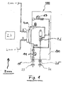
- FIG. 1 shows schematically an extracorporeal blood circuit 1000 and, in outline, a dialysate circuit 2000 of a treatment device 3000, for example a hemodiafiltration machine.
- the extracorporeal blood circuit 1000 has a medical functional device 100, e.g. B. a (disposable) blood cassette, is connected to it or at least partially integrated therein.
- a medical functional device 100 e.g. B. a (disposable) blood cassette
- the functional device 100 is functionally coupled to the treatment device 3000 and interacts with the pump drives, actuators and sensors in 1 only indicated treatment device 3000 together functionally.
- the pump drives, actuators and sensors of the treatment device 3000 functionally interact with a control and/or regulation device 27 of the treatment device 3000 . They can have a signal connection with the control and/or regulation device.
- the extracorporeal blood circuit 1000 is connected to a treatment device 200, for example a dialyzer or a blood filter.
- a blood pump 11 and a substituate pump 17 are arranged in or on the extracorporeal blood circuit 1000 .
- the blood pump 11 and the substituate pump 17 can deliver blood or substituate in a later treatment process.
- the blood pump 11 and/or the substituate pump 17 can be used as delivery device(s) for delivering the fluid for the purpose of filling the extracorporeal blood circuit 1000.
- the extracorporeal blood circuit 1000 has an arterial air bubble detector 15 (also referred to as “art. ABD ” for “arterial air bubble detector”). It also has a venous air bubble detector 25 (also referred to as “ ven . ABD ” for “venous air bubble detector”). For example, the venous air bubble detector 25 can be used as a detection device for detecting a fill level in the extracorporeal blood circuit 1000 .
- the invention is used to determine the volume of fluid that is required to fill the extracorporeal blood circuit 1000 , ie the blood side of the line system, by the treatment device 3000 .
- the volume of the fluid introduced to fill the extracorporeal blood circuit 1000 is recorded, which is required for level detection (e.g. in a venous chamber 26) or a message by the venous air bubble detector 25 trigger.
- the detected volume can, for. B. by determining the required rotor rotations of the blood pump 11 and / or the substituate pump 17 or by weighing a liquid bag with fresh rinsing / substituate solution.
- the recorded volume can be multiplied by a factor in order to be able to specify or set the required flushing volume.
- the volume determined is used to identify a blood tubing set that is used.
- the identification of the blood tubing set can e.g. This can be done, for example, using a comparison table in which typical filling volumes for different disposable configurations or blood tubing/blood filter combinations are stored.
- the comparison table is in some embodiments of the invention within the control and / or Control device 27 is stored in a data memory or can be stored in this according to the invention.
- control and/or regulation device 27 has a device for evaluating measurement data and calculating a delivery volume, in particular the cumulative delivery volume from the measurement data.
- it can have a device for comparing the calculated delivery volume with the data from the comparison table, as well as a device for assigning the calculated delivery volume to certain predefined blood tubing sets from the comparison table.
- the aforementioned devices can be combined in a single device.
- the determined volume is used to identify the treatment device 200 used, e.g. B. a dialyzer used.
- FIG. 2 shows different filling volumes V (in ml) of a first extracorporeal blood circuit for a single-needle treatment (its associated values are marked with squares), a second extracorporeal blood circuit for a double-needle treatment (its associated values are marked with rhombuses), and a third extracorporeal blood circuit for a blood cassette (its associated values are marked with crosses).
- the filling volume of the first blood circuit (squares) is 166 ml.
- the filling volume of the second blood circuit (diamonds) is 130 ml.
- the filling volume of the third blood circuit (crosses) is 97 ml.
- the method comprises setting parameters or parameter values for process control in the subsequent treatment, e.g. B. Definition of maximum/minimum permissible pump rates (small dialyzers have smaller recommended blood flows than larger ones), automatic definition of reinfusion volumes, or similar.
- Table 1 reflecting this is shown below for the minimum flow min_Flow and the maximum flow max_Flow for the above blood filters A to G having different capacity or blood volumes.
- Table 1 blood filter blood volume min_flow max_flow A 32 50 200 B 74 150 400 C 95 200 500 D 116 250 600 E 97 150 400 f 118 200 500 G 138 300 600
- a minimum or a maximum flow (rate) min Flow or max_Flow which depends on the type of blood filter, can be set automatically.
- FIG. 3 shows a schematic depiction of a further extracorporeal blood circuit 1000.
- the method disclosed, not according to the invention, can be carried out on the extracorporeal blood circuit 1000, for example, as follows.
- the blood purification device 200 is a dialyzer: After a patient, shown very schematically and denoted by the reference numeral 35, is connected to the extracorporeal blood circuit 1000, the blood pump 11 starts up with a constant blood flow Q_B (ml/min). The blood flows past a first sensor 37 into the extracorporeal blood circuit 1000 via the arterial blood hose clamp 29 of the arterial leg.
- the inflowing blood is detected by the first sensor 37 (for example an optical sensor, for example an optical sensor for measuring at least one blood parameter) at a first point in time t1 (sec).
- the first sensor 37 for example an optical sensor, for example an optical sensor for measuring at least one blood parameter
- the blood in the venous leg is detected by means of a second sensor 39, for example an optical sensor, if it is (already) present there.
- Blood can be detected by means of the second sensor 39 purely by way of example by means of infrared transmission measurement.
- the second sensor 39 can be connected to a device for detecting air bubbles or can be present in a common assembly. In some embodiments according to the invention, it is arranged upstream of the venous blood hose clamp 31 . In certain In the embodiments according to the invention, it is arranged downstream of the venous chamber 26 or the venous bladder chamber.
- extracorporeal blood circuit 1 Components in the extracorporeal blood circuit 1 are shown, the extracorporeal blood circuit can also 3 have, and vice versa.
Landscapes
- Health & Medical Sciences (AREA)
- Heart & Thoracic Surgery (AREA)
- Vascular Medicine (AREA)
- Biomedical Technology (AREA)
- Engineering & Computer Science (AREA)
- Anesthesiology (AREA)
- Cardiology (AREA)
- Hematology (AREA)
- Life Sciences & Earth Sciences (AREA)
- Animal Behavior & Ethology (AREA)
- General Health & Medical Sciences (AREA)
- Public Health (AREA)
- Veterinary Medicine (AREA)
- External Artificial Organs (AREA)
Description
- Die vorliegende Erfindung betrifft eine Steuer- oder Regelungseinrichtung gemäß Anspruch 1 und eine Behandlungseinrichtung gemäß Anspruch 18.
- Extrakorporale Blutkreisläufe erfahren in der Praxis vor ihrer Verwendung in einem medizinischen Behandlungsverfahren eine Vorbereitung. Die zur Behandlung mit dem extrakorporalen Blutkreislauf eingesetzte Behandlungsvorrichtung wird in der Praxis vor Behandlungsbeginn an die anstehende Behandlungsmodalität und/oder an die verwendeten (Einweg-)Artikel wie Blutkreislauf oder Blutfilter angepasst. Zu diesem Zweck wird der extrakorporale Blutkreislauf üblicherweise vor seinem Gebrauch mit einem Fluid (beispielsweise einer Substituatlösung) befüllt und hiermit gespült um möglicherweise vorhandene Produktionsrückstände und/oder Luftblasen aus dem extrakorporalen Blutkreislauf zu entfernen; an der Behandlungsvorrichtung wird gelegentlich eingestellt, mit welcher Behandlungsmodalität behandelt werden soll oder darf, oder von welchem Typ oder von welcher Größe der eingesetzte Blutfilter oder Blutkreislauf ist. Sowohl zum Bestimmen eines Mindestspülvolumens für den Blutkreislauf als auch für das Einstellen der Behandlungsvorrichtung auf die verwendeten (Einweg-)Artikel ist es erforderlich, wenigstens einen Parameter hierüber zu kennen.
- Krivitski et al. ("In vivo measurement of hemodialyzer fiber bundle volume: theory and validation"; Kidney International; Bd. 54, Nr. 5, 1998, Seiten 1751-1758) offenbart ein Verfahren zum Ermitteln des Volumens eines Dialysators.
-
EP0416808 A1 offenbart eine Vorrichtung zur Messung des Flusses in einer Leitung. -
WO2010/133319 offenbart eine Vorrichtung und ein Verfahren zur Erkennung eines Schlauchleitungssystems für eine extrakorporale Blutbehandlungsvorrichtung. - Eine Aufgabe der vorliegenden Erfindung ist es, eine Steuer- oder Regelungseinrichtung und eine Behandlungsvorrichtung, mit welcher das offenbarte Verfahren zum, vorzugsweise automatischen, Ermitteln wenigstens eines Parameters eines extrakorporalen Blutkreislaufs durchführbar ist, anzugeben.
- Die erfindungsgemäße Aufgabe wird durch eine Steuer- oder Regelungseinrichtung mit den Merkmalen des Anspruchs 1 gelöst. Sie wird zudem durch eine Behandlungsvorrichtung mit den Merkmalen des Anspruchs 18
- Die erfindungsgemäße Steuer- oder Regelungseinrichtung ist konfiguriert zur Durchführung eines Verfahrens zum Ermitteln wenigstens eines Parameters eines extrakorporalen Blutkreislaufs, wobei der extrakorporale Blutkreislauf eine Behandlungseinrichtung aufweist, mit den Schritten:
- Befüllen eines extrakorporalen Blutkreislaufs durch Einbringen eines Fluids, Fördern des Fluides durch den extrakorporalen Blutkreislauf oder Abschnitte hiervon, mittels einer Blutpumpe bei konstantem und/oder vorbestimmtem Fluss (Q_B) der Blutpumpe, und Bestimmen oder Errechnen einer Laufzeit des mittels der Blutpumpe in den extrakorporalen Blutkreislauf, oder Abschnitte hiervon, geförderten Fluids; und
- Erfassen, Ermitteln oder Berechnen der Größe eines Volumens des eingebrachten Fluids, welches zum Befüllen des extrakorporalen Blutkreislaufs oder eines definierten oder vorbestimmten Abschnitts hiervon erforderlich ist;
- Weiterverarbeiten der Größe des erfassten Volumens des Fluids zum Erhalt des wenigstens einen Parameters des extrakorporalen Blutkreislaufs; wobei der Parameter eine Angabe ist, welche den extrakorporalen Blutkreislauf unterscheidbar macht, seine Typenzugehörigkeit, seine Klassenzugehörigkeit, seine Eignung für bestimmte Behandlungsmodalitäten oder -verfahren oder seine Eignung zur Verwendung mit bestimmten Behandlungsvorrichtungen angibt oder Aussagen über einzelne Komponenten hiervon macht, dadurch gekennzeichnet, dass das Verfahren den Schritt umfasst: Vergleichen des ermittelten Parameters mit Parametern einer Vielzahl einseztbarer Behandlungseinrichtungen zur Identifikation der verwendeten Behandlungseinrichtung.
- Bei allen folgenden Ausführungen ist der Gebrauch des Ausdrucks "kann sein" bzw. "kann haben" usw. synonym zu "ist vorzugsweise" bzw. "hat vorzugsweise" usw. zu verstehen und soll erfindungsgemäße Ausführungsformen erläutern.
- Ein extrakorporaler Blutkreislauf weist in bestimmten Ausführungsformen der vorliegenden Erfindung eine medizinische Funktionseinrichtung auf. Diese Funktionseinrichtung kann beispielsweise eine (insbesondere als Disposable ausgestaltete) Blutkassette, und/oder eine Behandlungseinrichtung, wie beispielsweise einen Dialysator oder einen Blutfilter, und/oder einen Blutschlauchsatz aufweisen oder hieraus bestehen.
- Die Größe des Volumens (auch kurz: das Volumen) ist in manchen erfindungsgemäßen Ausführungsformen ein Zahlenwert mit einer Dimension (wie ml; Milliliter) oder ohne Dimension. In anderen erfindungsgemäßen Ausführungsformen wird hierunter eine Klassifizierung des Volumens oder seine Zuordnung zu bestimmten Volumenklassen verstanden.
- Das "Befüllen" bezeichnet in bestimmten Ausführungsformen der vorliegenden Erfindung das Einbringen oder Einfüllen von - insbesondere medizinischem - Fluid, z. B. Substituat-und/oder Dialysierflüssigkeit, in den extrakorporalen Blutkreislauf. Das Befüllen erfolgt in einigen erfindungsgemäßen Ausführungsformen einmalig und/oder initial, d. h. vor Beginn der Behandlung des Patienten, beispielsweise eines Blutbehandlungsverfahrens, z. B. einer Dialyse (Hämodialyse, Hämofiltration, Hämodiafiltration oder dergleichen) und/oder vor Beginn des Spülvorgangs.
- In bestimmten Ausführungsformen der vorliegenden Erfindung ist das Befüllen im Sinne der vorliegenden Erfindung vor Beginn des Spülvorgangs begonnen, erfolgt oder abgeschlossen.
- Der extrakorporale Blutkreislauf wird in manchen erfindungsgemäßen Ausführungsformen beim Befüllen vollständig oder im Wesentlichen vollständig mit Fluid befüllt.
- Dabei wird in einigen erfindungsgemäßen Ausführungsformen so viel Fluid in den extrakorporalen Blutkreislauf eingebracht, dass das eingebrachte Volumen einem Innenvolumen oder einem maximalen (Aufnahme-)Volumen des extrakorporalen Blutkreislaufs (mit oder ohne hiermit in Fluidverbindung stehenden Komponenten wie einem Blutfilter oder einer Blutkassette) entspricht.
- Um das Volumen des extrakorporalen Blutkreislaufs oder eines Abschnitts hiervon zu erfassen, muss der extrakorporale Blutkreislauf in manchen erfindungsgemäßen Ausführungsformen nicht vollständig mit Fluid befüllt werden.
- So wird in bestimmten Ausführungsformen der vorliegenden Erfindung der extrakorporale Blutkreislauf zum Beispiel nur teilweise, beispielsweise bis zu einem bestimmten Punkt, z. B. einer im oder am extrakorporalen Blutkreislauf angeordneten Erkennungseinrichtung, eingesetzt zum Erkennen eines Fluids oder zum Erkennen eines Wechsels zwischen unterschiedlichen Fluiden, mit Fluid befüllt.
- In manchen Ausführungsformen kann beispielsweise vorgesehen sein, das (Füll-)Volumen oder Gesamtvolumen oder Gesamtinnenvolumen oder Fassungsvermögen des extrakorporalen Blutkreislaufs hochzurechnen oder abzuschätzen. Diese Hochrechung oder Abschätzung stützt sich auf die Größe des erfassten Volumens (beispielsweise ist dies der befüllte Abschnitt des extrakorporalen Blutkreislaufs zwischen dem Einbringungsort des Fluids und dem Erkennungsort) und auf die Kenntnis des verbleibenden Teils des gesamten extrakorporalen Blutkreislaufs.
- Das in den extrakorporalen Blutkreislauf eingebrachte Fluid ist in manchen erfindungsgemäßen Ausführungsformen eine Priming- und/oder Spülflüssigkeit, beispielsweise eine Substituatflüssigkeit.
- In allen Ausführungsformen umfasst das Verfahren das Weiterverarbeiten der erfassten Größe des Volumens des Fluids. Das Weiterverarbeiten dient in den erfindungsgemäßen Ausführungsformen zum Erhalten des wenigstens einen Parameters des extrakorporalen Blutkreislaufs.
- Das Weiterverarbeiten der erfassten Größe ist oder umfasst in einigen erfindungsgemäßen Ausführungsformen ein Treffen einer Aussage über den Parameter.
- Das Weiterverarbeiten der erfassten Größe des Volumens ist oder umfasst in einigen erfindungsgemäßen Ausführungsformen ein Umrechnen des Wertes des Volumens über Algorithmen, Funktionen oder Zusammenhänge zum Erhalt des Parameters. Sie können in einer Speichereinrichtung, z. B. einer Speicheroder Steuereinrichtung einer Behandlungsvorrichtung, hinterlegt sein oder werden.
- Das Weiterverarbeiten der erfassten Größe des Volumens ist oder umfasst in manchen erfindungsgemäßen Ausführungsformen ein Mitteilen des erhaltenen Parameters an eine Aufsichtsperson, in anderen Ausführungsformen hingegen nicht. Das Weiterverarbeiten der erfassten Größe des Volumens ist oder umfasst in bestimmten erfindungsgemäßen Ausführungsformen ein Vergleichen des erfassten Volumens mit zur Ermittlung des Parameters geeigneten Größen oder Angaben (beispielsweise anhand einer Vergleichstabelle).
- Das Weiterverarbeiten der erfassten Größe des Volumens ist oder umfasst in gewissen erfindungsgemäßen Ausführungsformen ein Zuordnen eines Parameters zum extrakorporalen Blutkreislauf und/oder zu einzelnen Komponenten hiervon basierend auf der erfassten Größe des Volumens.
- Das Weiterverarbeiten der erfassten Größe des Volumen umfasst in manchen erfindungsgemäßen Ausführungsformen ein Mitteilen des Parameters an eine Aufsichtsperson (beispielsweise mittels Displayanzeige, Fehlermeldung, Alarm oder dergleichen), in anderen nicht.
- Ein Parameter ist eine Angabe, welche charakteristisch für den verwendeten extrakorporalen Blutkreislauf ist, und zwar alternativ ausschließlich (die Angabe oder der Parameter ist eindeutig nur dem verwendeten extrakorporalen Blutkreislauf oder dem verwendeten Typ von extrakorporalen Blutkreisläufen zugeordnet) oder nicht ausschließlich (die Angabe oder der Parameter ist neben dem verwendeten extrakorporalen Blutkreislauf oder dem verwendeten Typ von extrakorporalen Blutkreisläufen auch weiteren Blutkreisläufen oder Typen von extrakorporalen Blutkreisläufen zugeordnet, lässt aber dennoch eine gewisse Zuordnung, etwa zu einer abgeschlossenen Gruppe von extrakorporalen Blutkreisläufen, zu).
- Das Volumen des Fluids, welches zum Befüllen des extrakorporalen Blutkreislaufs in diesen eingebracht wird, ist in bestimmten Ausführungsformen der vorliegenden Erfindung ein kumuliertes Volumen.
- Ein kumuliertes Volumen bezeichnet in bestimmten Ausführungsformen der vorliegenden Erfindung das gesamte zum erstmaligen oder einmaligen, insbesondere zum vollständigen oder im Wesentlichen vollständigen, Befüllen des extrakorporalen Blutkreislaufs eingebrachte Volumen an Fluid. Das kumulierte Volumen umfasst also auch Teilvolumina, welche zum Erzielen des erstmaligen Befüllens des extrakorporalen Blutkreislaufs z. B. aufgrund einer während und aufgrund des Befüllens erfolgenden Entlüftung des extrakorporalen Blutkreislaufs zum Erzielen des angestrebten Befüllens ersetzt oder nachgefüllt werden müssen.
- Das Erreichen des befüllten Zustands des extrakorporalen Blutkreislaufs wird mittels einer Erkennungseinrichtung zum Erkennen eines Fluids oder eines Fluidzustands (wie einer Färbung, eines Mischungsverhältnisses, eines Wechsels unterschiedlicher Fluide, etwa eines Verdrängens von Luft durch das Fluid, einer Grenze zwischen einem flüssigen Fluid und Luft, usw.) festgestellt.
- Die Erkennungseinrichtung ist in gewissen Ausführungsformen der vorliegenden Erfindung im oder am extrakorporalen Blutkreislauf angeordnet. In einigen erfindungsgemäßen Ausführungsformen steht sie mit diesem in Wirk- oder Signalverbindung.
- In bestimmten Ausführungsformen der vorliegenden Erfindung ist die Erkennungseinrichtung ausgewählt aus Pegeldetektoren (beispielsweise Ultraschall-Pegeldetektoren, kapazitiven Pegeldetektoren, optischen Pegeldetektoren oder dergleichen), Luftdetektoren (beispielsweise Luftblasendetektoren), venösen Blasenfängern, oder dergleichen, oder Kombinationen hiervon, welche nach demselben physikalischen Prinzip oder nach unterschiedlichen Prinzipien arbeiten.
- In allen Ausführungsformen der vorliegenden Erfindung wird eine Laufzeit eines mittels einer Blutpumpe in extrakorporalen Blutkreislauf geförderten Fluids (welches in diesen Ausführungsformen beispielsweise Dialysierflüssigkeit, Substituatflüssigkeit oder Blut ist) bestimmt oder errechnet. In diesen Ausführungsformen umfasst das Verfahren das Fördern des Fluids durch den extrakorporalen Blutkreislauf oder Abschnitte hiervon mittels einer Pumpe, beispielsweise der Blutpumpe. Diese fördert entsprechend eines gewünschten konstanten Flusses oder eines nichtkonstanten aber auf andere Weise vorbestimmten Flussverlaufs, welcher eine Berechnung des innerhalb einer betrachteten Zeitspanne geförderten Fluidvolumens erlaubt. Ein solcher vorbestimmter Fluss kann beispielsweise ein sich kontinuierlich verstärkender Fluss oder ein sich zu vorbestimmten Zeitpunkten sprungweise erhöhender Fluss bei bekannter Sprunghöhe sein.
- In diesen Ausführungsformen wird der Zeitpunkt des Auftretens des Fluids an einem ersten Sensor des extrakorporalen Blutkreislaufs ermittelt. Dieser Zeitpunkt wird als erster Zeitpunkt bezeichnet.
- In diesen Ausführungsformen wird der Zeitpunkt des Auftretens des Fluids an einem zweiten Sensor des extrakorporalen Blutkreislaufs ermittelt. Dieser Zeitpunkt wird als zweiter Zeitpunkt bezeichnet.
- In diesen Ausführungsformen wird die Zeitdifferenz zwischen dem ersten Zeitpunkt und dem zweiten Zeitpunkt ermittelt.
- In diesen Ausführungsformen ist das Erfassen, Ermitteln oder Berechnen der Größe des Volumens des eingebrachten Fluids eine Multiplikation der Zeitdifferenz mit der konstanten Flussrate der Blutpumpe oder umfasst eine solche Multiplikation.
- In diesen Ausführungsformen kann das Volumen des extrakorporalen Blutkreislaufs somit anhand der Laufzeit des Fluids, beispielsweise des Bluts, vom ersten Sensor zum zweiten Sensor ermittelt werden, wenn die Förderleistung oder -menge der verwendeten Pumpe, hier nur beispielsweise einer Blutpumpe, bekannt ist. Die Förderleistung oder -menge der Pumpe kann sich aus einer als konstant oder anderweitig bekannten Förderrate der Pumpe zwischen dem ersten und dem zweiten Zeitpunkt ergeben.
- Auf diese Weise lässt sich anhand der Zeitdifferenz oder der Laufzeit und der Pumpenrate, - leistung oder der -menge pro Zeit das Gesamtvolumen des geförderten Fluids und damit das von den Schlauchabschnitten und der Behandlungseinrichtung (z. B. einem Dialysator) gemeinsam aufgenommene Füllvolumen bestimmen.
- Ist das Füllvolumen des extrakorporalen Blutkreislaufs, insbesondere der Schlauchabschnitte hiervon, bekannt, so lässt sich der verwendete Typ der Behandlungseinrichtung (z. B. des Dialysators) bestimmen, da jeder Typ einer Behandlungseinrichtung ein für ihn typisches Volumen aufnimmt.
- Jeder der hierin genannten optischen Sensoren kann ein venöser Blutdetektor (zum Detektieren von Blut im venösen Schenkel des extrakorporalen Blutkreislaufs) auf optischer Basis, ein optischer Sensor zur Messung wenigstens eines Blutparameters, oder jeder andere Typ eines Sensors sein. Unter einem solchen Blutparameter sind u. a. das relative Blutvolumen, die Hämoglobinkonzentration und der Hämatokrit zu verstehen. Andere optische Detektoren, welche verwendet werden können, sind nicht zum Messen von Blutparametern ausgestaltet.
- Ein wie vorstehend beschriebener optischer Sensor zur Messung wenigstens eines Blutparameters ist in gewissen Ausführungsformen der vorliegenden Erfindung eine Vorrichtung für Messungen im Blut wie sie in der Offenlegungsschrift
EP 1 748 292 A1 und/oder in der OffenlegungsschriftWO 2004/057313 A1 offenbart ist. - Ein optischer Sensor zur Messung wenigstens eines Blutparameters kann insbesondere eine Vorrichtung sein, welche eine Messeinheit aufweist, die einen Lichtemitter und einen Lichtdetektor aufweist. Hiermit wird Licht mit einer vorgegebenen Wellenlänge in einen Abschnitt des extrakorporalen Blutkreislaufs eingebracht, beispielsweise in den arteriellen Abschnitt. Der Abschnitt ist für Licht, insbesondere Infrarotlicht, durchlässig. Mit dem Lichtdetektor wird aus dem Abschnitt austretendes Licht empfangen. Mittels des optischen Sensors zur Messung wenigstens eines Blutparameters kann das Vorliegen von Fluid, beispielsweise Blut, im Abschnitt erkannt werden. Dies kann beispielsweise anhand des Verhältnisses zwischen der Intensität des ein- und der Intensität des austretenden Lichts erfolgen.
- In einigen erfindungsgemäßen Ausführungsformen ist der optische Sensor zur Messung wenigstens eines Blutparameters ausgestaltet, um weitere Blutparameter wie relatives Blutvolumen, Hämoglobinkonzentration, Hämatokrit zu messen. Die Steuereinrichtung ist entsprechend konfiguriert oder eingerichtet.
- Wird die Anwesenheit von Fluid mittels Licht festgestellt, so ist in bestimmten erfindungsgemäßen Ausführungsformen die Verwendung von Licht mit einer Wellenlänge von 790 bis 820 nm, bevorzugt von 800 bis 810 nm und besonders bevorzugt von 805 nm vorgesehen.
- Soll die Anwesenheit von Fluid mittels Licht festgestellt werden, so sind in manchen erfindungsgemäßen Ausführungsformen der Lichtemitter und der Lichtdetektor an einem Abschnitt des extrakorporalen Blutkreislaufs für eine Messung in diesem Abschnitt oder durch diesen hindurch angeordnet, welcher zwischen der arteriellen Patientennadel und der Blutpumpe liegt.
- Dieser Abschnitt ist in gewissen erfindungsgemäßen Ausführungsformen steifer (hierin auch als stabiler geführt oder aufgenommen bezeichnet) als wenigstens ein anderer Abschnitt des extrakorporalen Blutkreislaufs, als ein stromabwärts der Blutpumpe angeordneter Abschnitt, oder als alle anderen Abschnitte des extrakorporalen Blutkreislaufs. Der steifere Abschnitt ist in manchen erfindungsgemäßen Ausführungsformen ein Abschnitt, welcher zumindest teilweise an seinem Äußeren oder Umfang von einer Begrenzung oder Manschette (im Folgenden kurz: Manschette) umgeben ist. Die Manschette übt in gewissen erfindungsgemäßen Ausführungsformen Druck auf den durch sie hindurch geführten Abschnitt aus, beispielsweise derart, dass der Abschnitt im Inneren der Manschette ein anderes Querschnittprofil aufweist als vor und/oder hinter der Manschette. Aus diesem Grund kann er als steif(er) bezeichnet werden. Dies kann die Messgenauigkeit mittels Lichtdetektor vorteilhaft erhöhen. Beispielsweise kann der an sich runde oder kreisförmige Querschnitt des Blutschlauchs in der Manschette in einen eher eckigen oder viereckigen Querschnitt oder einen Querschnitt mit wenigstens einer oder zwei geraden Seitenflächen geformt werden. Ein Beispiel einer solchen Manschette oder der ihr zugrunde liegenden Idee ist in den oben genannten Offenlegungsschriften
EP 1 748 292 A1 undWO 2004/057313 A1 offenbart, siehe beispielsweise jeweils die Fig. 1 bis 5 dort. - Insbesondere kann die Pressung des Blutschlauchs durch die Manschette einen vorbestimmten Druck und/oder eine vorbestimmte Form- oder Querschnittsveränderung bewirken. Der Blutschlauchabschnitt kann somit auf definierte Weise verpresst oder gepresst sein.
- Insbesondere kann die Manschette in gewissen erfindungsgemäßen Ausführungsformen ausgestaltet sein als ein längliches Behältnis.
- Insbesondere kann die Manschette in gewissen erfindungsgemäßen Ausführungsformen ausgestaltet sein mit Aufnahmen oder Durchlässen für Lichtemitter und/oder Lichtdetektor.
- Sowohl der erste Sensor als auch der zweite Sensor können unabhängig voneinander als Sensoren ausgestaltet sein, welche mittels Messung der optischen Dichte, Ultraschallmessung, Akustikmessung oder Temperaturmessung die Anwesenheit von Fluid feststellen.
- In einigen Ausführungsformen der vorliegenden Erfindung wird die ermittelte Zeitdifferenz zu Zwecken der Verfahrenssteuerung der Blutbehandlung oder des Abrüstens der Blutbehandlungsvorrichtung nach abgeschlossener Behandlung genutzt. Beispielsweise kann die Kenntnis der Zeitdifferenz für einen automatischen Stopp der Reinfusion des Blutes nach Behandlungsende verwendet werden.
- In gewissen Ausführungsformen der vorliegenden Erfindung ist die Erkennungseinrichtung dazu vorgesehen, eine Fluid-Luft-Grenze zu erkennen. Sie kann somit angeben, wann die im (noch unbenutzten) extrakorporalen Blutkreislauf befindliche Luft stromaufwärts der Erkennungseinrichtung durch das eingefüllte Fluid verdrängt und beispielsweise über eine Entlüftungseinrichtung aus dem extrakorporalen Blutkreislauf entfernt wurde.
- In bestimmten Ausführungsformen der vorliegenden Erfindung wird das Volumen des Fluids über die (Anzahl der) Rotordrehungen einer Fördereinrichtung, mittels welcher der extrakorporale Blutkreislauf befüllt wurde, erfasst.
- Bei der Fördereinrichtung kann es sich um eine Schlauchrollenpumpe handeln, zum Beispiel eine Schlauchrollenpumpe, welche in Behandlungsverfahren zum Fördern von Blut (Blutpumpe) und/oder Substituat (Substituatpumpe) und/oder Dialysat eingesetzt wird.
- In weiteren Ausführungsformen der vorliegenden Erfindung wird das Volumen des Fluids über die Gewichtsabnahme einer Quelle für das Fluid, z. B. eines Flüssigkeitsbeutels, erfasst. Die Gewichtsabnahme kann beispielsweise durch Wiegen des Flüssigkeitsbeutels erfasst werden.
- In bestimmten Ausführungsformen der vorliegenden Erfindung umfasst das offenbarte Verfahren das Vergleichen des ermittelten Parameters mit (erfassten und hinterlegten) Parametern einer Vielzahl einsetzbarer medizinischer Funktionseinrichtungen zur Identifikation oder Zuordnung des extrakorporalen Blutkreislaufs einer hierin vorliegenden oder verwendeten medizinischen Funktionseinrichtung oder Komponente. Ein solches Vergleichen entspricht in manchen erfindungsgemäßen Ausführungsformen dem oben diskutierten Weiterverarbeiten oder umfasst dieses.
- Das Vergleichen kann z. B. mittels einer Vergleichstabelle erfolgen.
- In allen Ausführungsformen der Erfindung umfasst das Verfahren das Vergleichen des ermittelten Parameters mit (erfassten und hinterlegten) Parametern einer Vielzahl einsetzbarer Behandlungseinrichtungen zur Identifikation einer verwendeten Behandlungseinrichtung.
- Die Vielzahl der einsetzbaren medizinischen Funktionseinrichtungen oder der einsetzbaren Behandlungseinrichtungen oder Informationen jeweils zu ihnen können in geeigneten Tabellen hinterlegt sein.
- Ein vor einer Verwendung des extrakorporalen Blutkreislaufs zu einer Behandlung üblicherweise erfolgendes Vorbereiten, beispielsweise durch Primen und/oder Spülen dient wie oben erwähnt dazu, etwaige Produktionsrückstände (bedingt durch die Produktion der Behandlungseinrichtung und/oder des Blutschlauchsatzes) und/oder Luft aus dem Blutkreislauf oder den hiermit verbundenen Komponenten zu entfernen. Die zum Spülen oder Primen erforderliche Fluidmenge oder das erforderliche Fluidvolumen ist üblicherweise größer als die zum einfachen Befüllen des extrakorporalen Blutkreislaufs erforderliche Fluidmenge bzw. das Fassungs- oder Fluidvolumen. Im Stand der Technik wird zum Primen/Spülen ein allgemein gültiges Mindestvolumen von z. B. 500 ml festgelegt. Diese Festlegung ist offensichtlich nicht auf den jeweils konkret verwendeten extrakorporalen Blutschlauchsatz und seine Komponenten, etwa den verwendeten Blutfilter, abgestimmt, angepasst oder gar optimiert.
- Das offenbarte, nicht-erfindungsgemäße Verfahren umfasst in bestimmten Ausführungsformen das Festlegen eines minimalen, optimalen und/oder maximalen Priming- oder Spülvolumens zum Primen oder Spülen des extrakorporalen Blutkreislaufs anhand des ermittelten Parameters. Damit wird das Priming- oder Spülvolumen anhand des ermittelten Parameters vorteilhaft auf den tatsächlich verwendeten extrakorporalen Blutkreislauf und seine Komponenten angepasst. Hierbei kann der Parameter beispielsweise das Füllvolumen des Blutkreislaufs oder dessen Typ sein.
- In gewissen Ausführungsformen kann ein Mindestspülvolumen V_min zur Vorbereitung des später erfolgenden Behandlungsverfahrens, welches nicht Gegenstand oder Teil der vorliegenden Erfindung ist, beispielsweise der folgenden mathematischen Funktion folgen:

- Hierbei ist V_min das Mindestspülvolumen bei der Vorbereitung des Behandlungsverfahrens; V_Set ist das Volumen der medizinischen Funktionseinrichtung, insbesondere eines Blutschlauchsatzes oder Blutschlauchsets; V_Dial ist das Volumen der Behandlungseinrichtung, insbesondere eines Dialysators oder Blutfilters; und a und b sind jeweils Zahlen oder Konstanten.
- In bestimmten Ausführungsformen ist a eine beliebige Zahl, welche Werte insbesondere von 1 bis 3 annehmen kann.
- In gewissen Ausführungsformen ist b eine beliebige Zahl, welche Werte insbesondere von 2 bis 5 annehmen kann.
- In manchen Ausführungsformen können in die Bestimmung des Priming- oder Spülvolumens weitere Faktoren, wie beispielsweise (Behandlungs-)Vorschriften oder dergleichen, eingehen.
- In bestimmten Ausführungsformen umfasst das Verfahren das Festlegen oder Beeinflussen einer Steuerung des (späteren) Behandlungsverfahrens unter Einbezug oder in Abhängigkeit des ermittelten Parameters.
- In einigen Ausführungsformen umfasst das offenbarte, nicht-erfindungsgemäße Verfahren das Festlegen von maximalen und/oder minimalen Pumpenraten, ein (automatisches) Festlegen von Reinfusionsvolumina oder dergleichen unter Einbezug oder in Abhängigkeit des ermittelten Parameters.
- In bestimmten erfindungsgemäßen Ausführungsformen sind Reinfusionsvolumina solche Volumina einer Flüssigkeit (z. B. Substituat, Dialysierflüssigkeit oder Spülflüssigkeit), welche erforderlich sind, um das nach Beendigung der Blutbehandlung noch im extrakorporalen Blutkreislauf enthaltene Blut aus diesem herauszuspülen mit dem Ziel, das Blut dem Patienten rückzuführen.
- In gewissen Ausführungsformen umfasst das offenbarte, nicht-erfindungsgemäße
- Verfahren das Sperren von Behandlungsmodalitäten und/oder das Einschränken von Behandlungsparametern des (späteren) Behandlungsverfahrens unter Einbezug oder in Abhängigkeit des ermittelten Parameters.
- Einige oder alle erfindungsgemäßen Ausführungsformen können einen oder mehrere der oben oder im Folgenden genannten Vorteile aufweisen.
- Die vorliegende Offenbarung stellt vorteilhaft ein einfaches und wenig aufwendiges Verfahren zur (weiteren) Automatisierung eines Behandlungsverfahrens bereit.
- Die vorliegende Erfindung ist vorteilhaft für alle Behandlungsvorrichtungen mit extrakorporalen Blutkreisläufen einsetzbar.
- Mittels der erfindungsgemäßen Steuer- oder Regelungseinrichtung ist es in manchen Ausführungsformen vorteilhaft möglich, basierend auf der beim initialen Befüllen eines extrakorporalen Blutkreislaufs gewonnenen Information des (Füll-)Volumens oder eines anderen Parameters wie des Typs des verwendeten Blutkreislaufs oder dergleichen eine individualisierte Vorgabe des während des nachfolgenden Spülens umzuwälzenden Flüssigkeitsvolumens zu machen. Dies kann zu einer optimalen Spülwirkung, einer Mindestspülwirkung und/oder zu einem sparsamen Verwenden an Spülfluid beitragen.
- Mittels der erfindungsgemäßen Steuer- oder Regelungseinrichtung ist es in einigen Ausführungsformen vorteilhaft möglich, basierend auf der beim initialen Befüllen eines extrakorporalen Blutkreislaufs gewonnenen Information des (Füll-)Volumens gewisse Behandlungsmodalitäten zuzulassen oder zu sperren, entsprechend der erkannten Eignung, Größe, oder des Typs von extrakorporalem Blutkreislauf und/oder verwendeter Behandlungsvorrichtung. Dies kann vorteilhaft dazu beitragen, die Vorbereitung einer Behandlung und/oder den Behandlungsablauf selbst weiter zu automatisieren. Hiermit kann ferner die Sicherheit des Systems sowie die Patientensicherheit erhöht werden.
- Die vorliegende Erfindung ist vorteilhaft besonders einfach implementierbar, da sie oft nur ein softwareseitiges Aufrüsten von sich bereits in Betrieb befindenden Behandlungsvorrichtungen umfasst.
- Ein derartiges Aufrüsten oder Nachrüsten kann z. B. durch Implementieren des Quell- oder Maschinencodes der Betriebssoftware in der Steuereinrichtung einer Behandlungsvorrichtung erfolgen.
- Im Folgenden wird die vorliegende Erfindung unter Bezugnahme auf die beigefügte Zeichnung, in welcher gleiche Bezugszeichen identische oder ähnliche Elemente bezeichnen, rein exemplarisch beschrieben. Es gilt:
- Fig. 1
- zeigt eine schematische Abbildung eines extrakorporalen Blutkreislaufs, welcher mittels des offenbarten, nicht-erfindungsgemäßen Verfahrens zu seiner Verwendung vorbereitet werden kann, sowie eines Dialysatkreislaufs;
- Fig. 2
- veranschaulicht das Füllvolumen verschiedener Dialysatoren und deren Identifizierbarkeit mittels des offenbarten, nicht-erfindungsgemäßen Verfahrens; und
- Fig. 3
- zeigt eine schematische Abbildung eines weiteren extrakorporalen Blutkreislaufs, welcher mittels des offenbarten, nicht-erfindungsgemäßen Verfahrens zu seiner Verwendung oder abschließenden Spülung vorbereitet werden kann.
-
Fig. 1 zeigt schematisch einen extrakorporalen Blutkreislauf 1000 sowie, andeutungsweise, einen Dialysatkreislauf 2000 einer Behandlungsvorrichtung 3000, beispielsweise einer Hämodiafiltrationsmaschine. - Der extrakorporale Blutkreislauf 1000 weist eine medizinische Funktionseinrichtung 100, z. B. eine (Disposable-)Blutkassette, auf, ist hiermit verbunden oder zumindest abschnittsweise hierin integriert.
- Die Funktionseinrichtung 100 ist an die Behandlungsvorrichtung 3000 funktional angekoppelt und wirkt mit den Pumpenantrieben, Aktoren und Sensoren der in
Fig. 1 nur angedeuteten Behandlungsvorrichtung 3000 funktional zusammen. Die Pumpenantriebe, Aktoren und Sensoren der Behandlungsvorrichtung 3000 wirken mit einer Steuer- und/oder Regelungseinrichtung 27 der Behandlungsvorrichtung 3000 funktional zusammen. Sie können mit der Steuer- und/oder Regelungseinrichtung in Signalverbindung stehen. - Verbunden ist der extrakorporale Blutkreislauf 1000 mit einer Behandlungseinrichtung 200, beispielsweise einem Dialysator oder einem Blutfilter.
- Im oder am extrakorporalen Blutkreislauf 1000 sind eine Blutpumpe 11 sowie eine Substituatpumpe 17 angeordnet. Die Blutpumpe 11 und die Substituatpumpe 17 können in einem später ablaufenden Behandlungsverfahren Blut bzw. Substituat fördern.
- Die Blutpumpe 11 und/oder die Substituatpumpe 17 können als Fördereinrichtung(en) zum Fördern des Fluids zum Zwecke des Befüllens des extrakorporalen Blutkreislaufs 1000 eingesetzt werden. Dasselbe gilt für eine nicht in Fig. 17 dargestellte Pumpe des Dialysatkreislaufs.
- Der extrakorporale Blutkreislauf 1000 weist einen arteriellen Luftblasendetektor 15 (auch als "art. ABD" bezeichnet für "arterial air bubble detector") auf. Er weist ferner einen venösen Luftblasendetektor 25 (auch als "ven. ABD" bezeichnet für "venous air bubble detector") auf. Beispielsweise kann der venöse Luftblasendetektor 25 als Erkennungseinrichtung zum Erkennen eines Füllzustandes in den extrakorporalen Blutkreislauf 1000 eingesetzt werden.
- Die Erfindung dient in einigen Ausführungsformen dazu, das Fluidvolumen, welches zum Füllen des extrakorporalen Blutkreislaufs 1000, d. h. der Blutseite des Leitungssystems, benötigt wird, durch die Behandlungsvorrichtung 3000 zu ermitteln.
- In bestimmten Ausführungsformen des offenbarten, nicht-erfindungsgemäßen Verfahrens wird hierzu das Volumen des zum Befüllen des extrakorporalen Blutkreislaufs 1000 eingebrachten Fluids erfasst, das erforderlich ist, um eine Pegeldetektion (z. B. an einer venösen Kammer 26) oder eine Meldung durch den venösen Luftblasendetektor 25 auszulösen. Das erfasste Volumen kann z. B. durch Ermitteln der benötigten Rotordrehungen der Blutpumpe 11 und/oder der Substituatpumpe 17 oder durch Wägung eines Flüssigkeitsbeutels mit frischer Spül-/Substituatlösung bestimmt werden. Das erfasste Volumen kann mit einem Faktor multipliziert werden, um das benötigte Spülvolumen angeben oder einstellen zu können.
- Fällt der Flüssigkeitspegel an der Detektionsstelle, d. h. am Erkennungsort oder an der Erkennungseinrichtung, während des Befüllens wieder ab, z. B. weil sich Restluft aus der Behandlungseinrichtung 200 löst, kann das zum erneuten Anheben des Pegels benötigte Volumen zum bereits ermittelten Volumen hinzuaddiert werden. Das weitere Verwenden des derart erfassten kumulierten Volumens kann dabei vorteilhaft die Genauigkeit der Bestimmung des erfassten Volumens erhöhen. Das ermittelte Volumen wird in bestimmten Ausführungsformen verwendet zur Identifikation eines verwendeten Blutschlauchsatzes. Die Identifikation des Blutschlauchsatzes kann z. B. anhand einer Vergleichstabelle erfolgen, in der typische Füllvolumina für verschiedene Disposablekonfigurationen oder Blutschlauch/Blutfilter-Kombinationen hinterlegt sind.
- Die Vergleichstabelle ist in einigen erfindungsgemäßen Ausführungsformen innerhalb der Steuer- und/oder Regelungseinrichtung 27 in einem Datenspeicher gespeichert oder kann erfindungsgemäß in diesem gespeichert werden.
- Die Steuer- und/oder Regelungseinrichtung 27 weist in manchen erfindungsgemäßen Ausführungsformen eine Einrichtung zum Auswerten von Messdaten und Berechnen eines Fördervolumens, insbesondere des kumulierten Fördervolumens aus den Messdaten, auf. Sie kann zusätzlich eine Einrichtung zum Vergleichen des berechneten Fördervolumens mit den Daten aus der Vergleichstabelle aufweisen, zudem eine Einrichtung zum Zuordnen des berechneten Fördervolumens zu bestimmten vorgegebenen Blutschlauchsätzen aus der Vergleichstabelle. Die vorgenannten Einrichtungen können in einer einzigen Einrichtung vereint vorliegen.
- So können z. B. vorteilhaft einfach unterschiedliche Blutschlauchsysteme für z. B. pädiatrische und Erwachsenen-Dialyse oder unterschiedliche Behandlungsverfahren (Single-Needle/Double-Needle) unterschieden werden. In Abhängigkeit des identifizierten Disposabletyps können an der Behandlungsvorrichtung, insbesondere automatisch und ohne Zutun der Aufsichtsperson, Behandlungsmodalitäten gesperrt und/oder Behandlungsparameter eingeschränkt werden.
- In weiteren Ausführungsformen wird das ermittelte Volumen verwendet zur Identifikation der eingesetzten Behandlungseinrichtung 200, z. B. eines eingesetzten Dialysators.
- Zur Verfeinerung der Identifikation können weitere (ergänzende) und der Behandlungsvorrichtung zur Verfügung stehende charakteristische Merkmale hinzugezogen werden (z. B. ein dialysatseitiges Füllvolumen, blut- und/oder dialysatseitige Strömungswiderstände, der Transmembrandruck und dergleichen).
- In
Fig. 1 sind ferner eine arterielle Blutschlauchklemme 29 sowie eine venöse Blutschlauchklemme 31 dargestellt. -
Fig. 2 zeigt verschiedene Füllvolumina V (in ml) eines ersten extrakorporalen Blutkreislaufs für eine Single-Needle-Behandlung (ihm zugehörige Werte sind mit Quadraten markiert), eines zweiten extrakorporalen Blutkreislaufs für eine Double-Needle-Behandlung (ihm zugehörige Werte sind mit Rauten markiert), und eines dritten extrakorporalen Blutkreislaufs für eine Blutkassette (ihm zugehörige Werte sind mit Kreuzen markiert). - Das Füllvolumen des ersten Blutkreislaufs (Quadrate) beträgt 166 ml. Das Füllvolumen des zweiten Blutkreislaufs (Rauten) beträgt 130 ml. Das Füllvolumen des dritten Blutkreislaufs (Kreuze) beträgt 97 ml. Diese Angaben gelten jeweils für den Blutkreislauf, solange dieser nicht mit einem Blutfilter verbunden ist.
-
Fig. 2 , zeigt, wie sich das Gesamtfüllvolumen der o. g. Blutkreisläufe erhöht, und unterschiedlich erhöht, sobald diese mit einem der Filter A, B, C, D, E, F oder G verbunden sind. - Aus
Fig. 2 ist somit gut zu sehen, dass die Kenntnis des Füllvolumens eines konkreten Blutkreislaufs bereits erkennen lässt, mit welchem Filter dieser im Moment seines Befüllens im Sinne der Erfindung verbunden ist. - In bestimmten Ausführungsformen des offenbarten, nicht-erfindungsgemäßen Verfahrens umfasst das Verfahren das Festlegen von Parametern oder Parameterwerten zur Verfahrenssteuerung in der nachfolgenden Behandlung, z. B. Festlegung maximal/minimal zulässiger Pumpenraten (kleine Dialysatoren haben kleinere empfohlene Blutflüsse als größere), automatische Festlegung von Reinfusionsvolumina, o. ä.
- Tabelle 1, welche dies widerspiegelt, ist im Folgenden für den minimalen Fluss min_Flow und den maximalen Fluss max_Flow für die o. g. Blutfilter A bis G, welche unterschiedliche Fassungs- oder Blutvolumen haben, gezeigt.
Tabelle 1 Blutfilter Blutvolumen min_Flow max_Flow A 32 50 200 B 74 150 400 C 95 200 500 D 116 250 600 E 97 150 400 F 118 200 500 G 138 300 600 - Für den Fachmann ist somit erkennbar, dass die Kenntnis des verwendeten Filtertyps, welcher mittels des offenbarten, nicht-erfindungsgemäßen Verfahrens ermittelt werden kann, auch für die Steuerung der Behandlungsvorrichtung während einer sich anschließenden Behandlung genutzt werden kann. So kann ein minimaler oder ein maximaler Fluss (Rate) min Flow oder max_Flow, welcher vom Typen des Blutfilters abhängt, automatisch eingestellt werden.
-
Fig. 3 zeigt eine schematische Abbildung eines weiteren extrakorporalen Blutkreislaufs 1000. Das offenbarte, nicht-erfindungsgemäße Verfahren kann am extrakorporalen Blutkreislaufs 1000 beispielsweise wie folgt ausgeführt werden. Dabei wird angenommen, dass die Blutreinigungseinrichtung 200 ein Dialysator ist:
Nachdem ein sehr schematisch dargestellter und mit dem Bezugszeichen 35 bezeichneter Patient mit dem extrakorporalen Blutkreislauf 1000 konnektiert ist, läuft die Blutpumpe 11 mit einem konstanten Blutfluss Q_B (ml/min) an. Das Blut strömt an einem ersten Sensor 37 vorbei über die arterielle Blutschlauchklemme 29 des arteriellen Schenkels in den extrakorporalen Blutkreislauf 1000 ein. - Das einströmende Blut wird dabei vom ersten Sensor 37 (beispielsweise einem optischer Sensor, beispielsweise einem optischen Sensor zur Messung wenigstens eines Blutparameters) zu einem ersten Zeitpunkt t1 (sec) erkannt.
- Zu einem zweiten Zeitpunkt t2 (sec) wird das Blut im venösen Schenkel mittels eines zweiten Sensors 39, beispielsweise einem optischen Sensor, erkannt, sofern es denn dort (bereits) vorliegt. Der Nachweis von Blut mittels des zweiten Sensors 39 kann rein exemplarisch mittels Infrarot-Transmissionsmessung erfolgen.
- Der zweite Sensor 39 kann in bestimmten erfindungsgemäßen Ausführungsformen mit einer Einrichtung zum Erkennen von Luftblasen verbunden sein oder in einer gemeinsamen Baugruppe vorliegen. Er ist in manchen erfindungsgemäßen Ausführungsformen stromaufwärts der venösen Blutschlauchklemme 31 angeordnet. In gewissen erfindungsgemäßen Ausführungsformen ist er stromabwärts der venösen Kammer 26 bzw. der venösen Blasenkammer angeordnet.
- Aus dem konstanten Blutfluss Q_B (ml/min) und der Zeitdifferenz zwischen dem ersten Zeitpunkt t1 (sec) und dem zweiten Zeitpunkt t2 (sec) kann das Volumen V_Set des gesamten extrakorporalen Blutkreislaufs 1000 wie folgt ermittelt werden:

- Aufgrund der bekannten Beziehung


- Bauteile, die im extrakorporalen Blutkreislauf der
Fig. 1 dargestellt sind, kann auch der extrakorporale Blutkreislauf derFig. 3 aufweisen, und umgekehrt.Bezugszeichenliste Bezugszeichen Bezeichnung 1000 Extrakorporaler Blutkreislauf 2000 Dialysatkreislauf 3000 Behandlungsvorrichtung 100 Medizinische Funktionseinrichtung 200 Behandlungseinrichtung 11 Blutpumpe 15 arterieller Luftblasendetektor 17 Substituatpumpe 25 venöser Luftblasendetektor 26 venöse Kammer 27 Steuer- und/oder Regelungseinrichtung 29 arterielle Blutschlauchklemme 31 venöse Blutschlauchklemme 35 Patient 37 optischer Sensor 39 optischer Sensor P Druckmesseinrichtungen
Claims (19)
- Steuer- oder Regelungseinrichtung (27), konfiguriert zur Durchführung eines Verfahrens zum Ermitteln wenigstens eines Parameters eines extrakorporalen Blutkreislaufs (1000), wobei der extrakorporale Blutkreislauf (1000) eine Behandlungseinrichtung (200) aufweist, mit den Schritten:- Befüllen eines extrakorporalen Blutkreislaufs (1000) durch Einbringen eines Fluids, Fördern des Fluides durch den extrakorporalen Blutkreislauf (1000) oder Abschnitte hiervon, mittels einer Blutpumpe (11) bei konstantem und/oder vorbestimmtem Fluss (Q_B) der Blutpumpe (11), und Bestimmen oder Errechnen einer Laufzeit des mittels der Blutpumpe (11) in den extrakorporalen Blutkreislauf (1000), oder Abschnitte hiervon, geförderten Fluids; und- Erfassen, Ermitteln oder Berechnen der Größe eines Volumens des eingebrachten Fluids, welches zum Befüllen des extrakorporalen Blutkreislaufs (1000) oder eines definierten oder vorbestimmten Abschnitts hiervon erforderlich ist;- Weiterverarbeiten der Größe des erfassten Volumens des Fluids zum Erhalt des wenigstens einen Parameters des extrakorporalen Blutkreislaufs (1000);wobei der Parameter eine Angabe ist, welche den extrakorporalen Blutkreislauf unterscheidbar macht, seine Größe angibt, seine Typenzugehörigkeit, seine Klassenzugehörigkeit, seine Eignung für bestimmte Behandlungsmodalitäten oder -verfahren oder seine Eignung zur Verwendung mit bestimmten Behandlungsvorrichtungen angibt oder Aussagen über einzelne Komponenten hiervon macht,
dadurch gekennzeichnet, dass
das Verfahren den Schritt umfasst:
Vergleichen des ermittelten Parameters mit Parametern einer Vielzahl einsetzbarer Behandlungseinrichtungen zur Identifikation der verwendeten Behandlungseinrichtung (200). - Steuer- oder Regelungseinrichtung (27) nach Anspruch 1, wobei das Fluid durch die Blutseite des Leitungssystems des extrakorporalen Blutkreislaufs (1000) gefördert wird.
- Steuer- oder Regelungseinrichtung (27) nach einem der Ansprüche 1 bis 2, wobei das Befüllen nach dem Konnektieren eines Patienten (35) mit dem extrakorporalen Blutkreislauf (1000) erfolgt.
- Steuer- oder Regelungseinrichtung (27) nach einem der vorangegangenen Ansprüche, wobei das in den extrakorporalen Blutkreislauf geförderte Fluid Blut ist.
- Steuer- oder Regelungseinrichtung (27) nach einem der vorangegangenen Ansprüche, wobei das Volumen des Fluids ein kumuliertes Volumen ist.
- Steuer- oder Regelungseinrichtung (27) nach einem der vorangegangenen Ansprüche, wobei das Verfahren die Schritte umfasst:- Fördern des Fluids durch den extrakorporalen Blutkreislauf (1000) oder Abschnitte hiervon bei konstantem und/oder vorbestimmtem Fluss (Q_B) der Blutpumpe (11);- Ermitteln des Zeitpunkts des Auftretens des Fluids an einem ersten Sensor (37) des extrakorporalen Blutkreislaufs (1000) als ersten Zeitpunkt (t1);- Ermitteln des Zeitpunkts des Auftretens des Fluids an einem zweiten Sensor (39) des extrakorporalen Blutkreislaufs (1000) als zweiten Zeitpunkt (t2);- Ermitteln der Zeitdifferenz zwischen dem ersten Zeitpunkt (t1) und dem zweiten Zeitpunkt (t2);wobei das Erfassen, Ermitteln oder Berechnen der Größe des Volumens des eingebrachten Fluids eine Multiplikation der Zeitdifferenz mit dem konstanten Fluss (Q_B) der Blutpumpe (11) ist oder umfasst.
- Steuer- oder Regelungseinrichtung (27) nach Anspruch 6, wobei der erste Sensor (37) und/oder der zweite Sensor (39) als optische Sensoren ausgestaltet sind.
- Steuer- oder Regelungseinrichtung (27) nach Anspruch 6, wobei der erste Sensor (37) und/oder der zweite Sensor (39) als Sensoren ausgestaltet sind, welche mittels Ultraschallmessung, Akustikmessung oder Temperaturmessung die Anwesenheit von Fluid feststellen.
- Steuer- oder Regelungseinrichtung (27) nach einem der Ansprüche 6 bis 8, wobei der erste Sensor (37) und/oder der zweite Sensor (39) optische Sensoren zur Messung wenigstens eines Blutparameters sind.
- Steuer- oder Regelungseinrichtung (27) nach einem der Ansprüche 6 bis 9, wobei der erste Sensor (37) stromaufwärts einer arteriellen Blutschlauchklemme (29) und der zweite Sensor (39) stromaufwärts einer venösen Blutschlauchklemme (31) und/oder stromabwärts einer venösen Kammer (26) oder einer venösen Blasenkammer angeordnet ist.
- Steuer- oder Regelungseinrichtung (27) nach einem der vorangegangenen Ansprüche, wobei die Erfassung mittels einer Erfassungseinrichtung erfolgt, welche wenigstens eine Erkennungseinrichtung zum Erkennen eines Fluids oder eines Fluidzustands aufweist oder hiermit verbunden ist, wobei die Erkennungseinrichtung ausgewählt ist aus der Gruppe, welche aus Pegeldetektoren, Luftdetektoren (15, 25), optische Detektoren, Ultraschalldetektoren, Schalldetektoren oder beliebigen Kombinationen hiervon besteht.
- Steuer- oder Regelungseinrichtung (27) nach Anspruch 11, wobei die Erkennungseinrichtung im oder am extrakorporalen Blutkreislauf angeordnet ist und/oder mit diesem in Wirk- oder Signalverbindung steht.
- Steuer- oder Regelungseinrichtung (27) nach einem der vorangegangenen Ansprüche, wobei das Erfassen oder Bestimmen des Volumens mittels der Steuer- oder Regelungseinrichtung (27) automatisch erfolgt.
- Steuer- oder Regelungseinrichtung (27) nach einem der vorangegangenen Ansprüche, wobei die Größe des Volumens des Fluids über die Rotordrehungen der Blutpumpe (11) zum Fördern des Fluids erfasst wird.
- Steuer- oder Regelungseinrichtung (27) nach einem der vorangegangenen Ansprüche, wobei das Verfahren den Schritt umfasst:- Festlegen einer Steuerung oder von Flussraten (min_Flow, max_Flow) des Behandlungsverfahrens unter Einbezug oder in Abhängigkeit des ermittelten Parameters.
- Steuer- oder Regelungseinrichtung (27) nach einem der vorangegangenen Ansprüche, wobei das Verfahren den Schritt umfasst:- Sperren von Behandlungsmodalitäten und/oder Einschränken von Behandlungsparametern des Behandlungsverfahrens bei Verwendung des extrakorporalen Blutkreislaufs (1000) in Abhängigkeit des ermittelten Parameters.
- Steuer- oder Regelungseinrichtung (27) nach einem der vorangegangenen Ansprüche, wobei das Verfahren den Schritt umfasst:- Festlegen von Reinfusionsvolumina unter Einbezug oder in Abhängigkeit des ermittelten Parameters.
- Behandlungsvorrichtung, welche eine Steuer- oder Regelungseinrichtung (27) gemäß einem der Ansprüche 1 bis 17 aufweist.
- Behandlungsvorrichtung nach Anspruch 18, welche als Dialysevorrichtung, Hämodialysevorrichtung, Hämofiltrationsvorrichtung, oder Hämodiafiltrationsvorrichtung ausgestaltet ist.
Applications Claiming Priority (4)
| Application Number | Priority Date | Filing Date | Title |
|---|---|---|---|
| US201161513005P | 2011-07-29 | 2011-07-29 | |
| DE201110108786 DE102011108786A1 (de) | 2011-07-29 | 2011-07-29 | Verfahren zum Ermitteln wenigstens eines Parameters eines extrakorporalen Blutkreislaufs sowie Vorrichtungen |
| EP12737205.0A EP2736559B1 (de) | 2011-07-29 | 2012-07-10 | Verfahren zum ermitteln wenigstens eines parameters eines extrakorporalen blutkreislaufs sowie vorrichtungen |
| PCT/EP2012/002908 WO2013017194A2 (de) | 2011-07-29 | 2012-07-10 | Verfahren zum ermitteln wenigstens eines parameters eines extrakorporalen blutkreislaufs sowie vorrichtungen |
Related Parent Applications (1)
| Application Number | Title | Priority Date | Filing Date |
|---|---|---|---|
| EP12737205.0A Division EP2736559B1 (de) | 2011-07-29 | 2012-07-10 | Verfahren zum ermitteln wenigstens eines parameters eines extrakorporalen blutkreislaufs sowie vorrichtungen |
Publications (2)
| Publication Number | Publication Date |
|---|---|
| EP3238765A1 EP3238765A1 (de) | 2017-11-01 |
| EP3238765B1 true EP3238765B1 (de) | 2022-05-18 |
Family
ID=47503059
Family Applications (2)
| Application Number | Title | Priority Date | Filing Date |
|---|---|---|---|
| EP12737205.0A Active EP2736559B1 (de) | 2011-07-29 | 2012-07-10 | Verfahren zum ermitteln wenigstens eines parameters eines extrakorporalen blutkreislaufs sowie vorrichtungen |
| EP17172308.3A Active EP3238765B1 (de) | 2011-07-29 | 2012-07-10 | Vorrichtungen zum ermitteln eines füllvolumens eines extrakorporalen blutkreislaufs |
Family Applications Before (1)
| Application Number | Title | Priority Date | Filing Date |
|---|---|---|---|
| EP12737205.0A Active EP2736559B1 (de) | 2011-07-29 | 2012-07-10 | Verfahren zum ermitteln wenigstens eines parameters eines extrakorporalen blutkreislaufs sowie vorrichtungen |
Country Status (6)
| Country | Link |
|---|---|
| US (2) | US9849228B2 (de) |
| EP (2) | EP2736559B1 (de) |
| JP (2) | JP6121999B2 (de) |
| CN (2) | CN103747821B (de) |
| DE (1) | DE102011108786A1 (de) |
| WO (1) | WO2013017194A2 (de) |
Families Citing this family (30)
| Publication number | Priority date | Publication date | Assignee | Title |
|---|---|---|---|---|
| EP3165245B1 (de) | 2011-08-02 | 2019-02-20 | Medtronic, Inc. | Hämodialysesystem mit einem durchflussweg mit gesteuertem nachgiebigem volumen |
| US9710610B2 (en) | 2012-07-25 | 2017-07-18 | Covidien Lp | Enteral feeding pump with flow adjustment |
| US11154648B2 (en) | 2013-01-09 | 2021-10-26 | Medtronic, Inc. | Fluid circuits for sorbent cartridge with sensors |
| US9713666B2 (en) | 2013-01-09 | 2017-07-25 | Medtronic, Inc. | Recirculating dialysate fluid circuit for blood measurement |
| US9623164B2 (en) | 2013-02-01 | 2017-04-18 | Medtronic, Inc. | Systems and methods for multifunctional volumetric fluid control |
| US10850016B2 (en) | 2013-02-01 | 2020-12-01 | Medtronic, Inc. | Modular fluid therapy system having jumpered flow paths and systems and methods for cleaning and disinfection |
| US10010663B2 (en) | 2013-02-01 | 2018-07-03 | Medtronic, Inc. | Fluid circuit for delivery of renal replacement therapies |
| EP2953662B1 (de) | 2013-02-06 | 2018-08-29 | NxStage Medical, Inc. | Flüssigkeitskreislauffüllverfahren |
| ES3010316T3 (en) | 2013-09-24 | 2025-04-02 | Kpr Us Llc | Feeding set and enteral feeding pump |
| US9884145B2 (en) | 2013-11-26 | 2018-02-06 | Medtronic, Inc. | Parallel modules for in-line recharging of sorbents using alternate duty cycles |
| US10537875B2 (en) | 2013-11-26 | 2020-01-21 | Medtronic, Inc. | Precision recharging of sorbent materials using patient and session data |
| US10357757B2 (en) | 2014-06-24 | 2019-07-23 | Medtronic, Inc. | Stacked sorbent assembly |
| US10172991B2 (en) | 2014-06-24 | 2019-01-08 | Medtronic, Inc. | Modular dialysate regeneration assembly |
| DE102014113462A1 (de) * | 2014-09-18 | 2016-03-24 | Fresenius Medical Care Deutschland Gmbh | Verfahren und Vorrichtung zum Berücksichtigen von Patientenfeedback bei der Blutbehandlung |
| JP6805165B2 (ja) | 2015-04-07 | 2020-12-23 | ネクステージ メディカル インコーポレイテッド | 血液処理装置のプライミングセット |
| CN105363085B (zh) * | 2015-12-10 | 2018-05-22 | 威海威高血液净化制品有限公司 | 血液净化装置 |
| US10981148B2 (en) | 2016-11-29 | 2021-04-20 | Medtronic, Inc. | Zirconium oxide module conditioning |
| US10960381B2 (en) | 2017-06-15 | 2021-03-30 | Medtronic, Inc. | Zirconium phosphate disinfection recharging and conditioning |
| US12285552B2 (en) | 2018-08-14 | 2025-04-29 | Mozarc Medical Us Llc | Precision dialysis therapy based on sorbent effluent analysis |
| US11213616B2 (en) | 2018-08-24 | 2022-01-04 | Medtronic, Inc. | Recharge solution for zirconium phosphate |
| DE102018010182A1 (de) * | 2018-12-31 | 2020-07-02 | Fresenius Medical Care Deutschland Gmbh | Vorrichtung zur Reinfusion von Patientenflüssigkeit |
| DE102019120171A1 (de) | 2019-07-25 | 2021-01-28 | Fresenius Medical Care Deutschland Gmbh | Dialysegerät mit einer Vorrichtung zur Identifikation eines Dialysators und Verfahren zur Identifikation eines Dialysators |
| US11413386B2 (en) * | 2019-08-09 | 2022-08-16 | Fresenius Medical Care Holdings, Inc. | Volume-based priming of dialysis machines |
| EP3991764B1 (de) | 2020-10-27 | 2024-03-06 | Bellco S.r.l. | Durchflussmesser zum dosieren von wasser in einem dialysesystem |
| EP3991770B1 (de) | 2020-10-30 | 2024-10-30 | Bellco S.r.l. | Dialysekassette mit pumpfunktionen |
| US12318528B2 (en) | 2020-10-30 | 2025-06-03 | Mozarc Medical Us Llc | Variable orifice fistula graft |
| EP4008376A1 (de) | 2020-12-03 | 2022-06-08 | Medtronic, Inc. | Flexibles rohr-routing-zubehör für peritoneal dialysis system |
| US12569601B2 (en) | 2021-04-07 | 2026-03-10 | Mozarc Medical Us Llc | Increased operational capabilities of a dialysis system |
| US12397093B2 (en) | 2021-05-18 | 2025-08-26 | Mozarc Medical Us Llc | Sorbent cartridge designs |
| DE102023108778A1 (de) * | 2023-04-05 | 2024-10-10 | B.Braun Avitum Ag | Verfahren zum automatischen Klassifizieren eines Dialysators und Verfahren zum Betreiben einer Dialysemaschine mit einem Dialysator |
Citations (1)
| Publication number | Priority date | Publication date | Assignee | Title |
|---|---|---|---|---|
| WO2010133319A1 (de) * | 2009-05-19 | 2010-11-25 | Fresenius Medical Care Deutschland Gmbh | Vorrichtung und verfahren zur erkennung eines schlauchleitungssystems für eine extrakorporale blutbehandlungsvorrichtung |
Family Cites Families (27)
| Publication number | Priority date | Publication date | Assignee | Title |
|---|---|---|---|---|
| JPS54103397A (en) | 1978-01-31 | 1979-08-14 | Matsushita Electric Works Ltd | Production of semiconductor gas detecting element |
| JPS56132961A (en) * | 1980-03-22 | 1981-10-17 | Daicel Ltd | Artificial kidney device |
| US4995268A (en) * | 1989-09-01 | 1991-02-26 | Ash Medical System, Incorporated | Method and apparatus for determining a rate of flow of blood for an extracorporeal blood therapy instrument |
| JPH03261480A (ja) * | 1990-03-09 | 1991-11-21 | Nissho Corp | 透析装置 |
| JPH03277372A (ja) * | 1990-03-28 | 1991-12-09 | Terumo Corp | 血液処理装置の製造方法 |
| JPH05168703A (ja) * | 1991-12-20 | 1993-07-02 | Ube Ind Ltd | 計量器を備えたポンプ |
| JP3254123B2 (ja) | 1996-02-14 | 2002-02-04 | テルモ株式会社 | 血液回路設計装置 |
| JP3803421B2 (ja) | 1996-04-26 | 2006-08-02 | 富士システムズ株式会社 | 気体交換装置 |
| US6270673B1 (en) | 1999-09-03 | 2001-08-07 | Baxter International Inc. | Door latching assembly for holding a fluid pressure actuated cassette during use |
| CN101259296B (zh) * | 1999-09-03 | 2012-12-19 | 汾沃有限公司 | 连续流入、脉动流出的流体压力致动血液泵送的方法 |
| JP3947037B2 (ja) * | 2002-04-26 | 2007-07-18 | 日機装株式会社 | 透析装置 |
| FR2839261B1 (fr) * | 2002-05-06 | 2006-04-07 | Ciposa Sa | Procede de nettoyage et de qulaification d'un filtre de dialyse et machine pour la mise en oeuvre de ce procede |
| WO2004057313A1 (en) | 2002-12-20 | 2004-07-08 | Optoq Ab | Method and device for measurements in blood |
| JP4313264B2 (ja) * | 2004-07-09 | 2009-08-12 | 有限会社 ノイエス | 血液浄化装置 |
| DE102005022545B4 (de) * | 2005-05-17 | 2007-02-15 | Fresenius Medical Care Deutschland Gmbh | Verfahren zum luftfreien Füllen der Blutseite einer Hämodialysevorrichtung mit einer physiologischen Elektrolytlösung |
| WO2007031809A1 (en) * | 2005-09-15 | 2007-03-22 | Gambro Lundia Ab | A process and an apparatus for filling and/or rinsing an extracorporeal blood circuit |
| JP4613831B2 (ja) * | 2006-01-17 | 2011-01-19 | ニプロ株式会社 | 血液浄化装置及びその血液循環路の自動プライミング方法 |
| US8409441B2 (en) * | 2007-02-27 | 2013-04-02 | Deka Products Limited Partnership | Blood treatment systems and methods |
| ES2402306T3 (es) | 2007-04-12 | 2013-04-30 | Gambro Lundia Ab | Método y aparato para cebar un circuito de sangre extracorporal |
| US7892197B2 (en) * | 2007-09-19 | 2011-02-22 | Fresenius Medical Care Holdings, Inc. | Automatic prime of an extracorporeal blood circuit |
| US8858787B2 (en) * | 2007-10-22 | 2014-10-14 | Baxter International Inc. | Dialysis system having non-invasive fluid velocity sensing |
| EP3620191B1 (de) | 2008-01-23 | 2023-12-13 | DEKA Products Limited Partnership | Vorrichtung zum automatischen anschluss an eine flüssigkeitsleitung und verfahren für ein medizinisches behandlungssystem |
| JP2009297339A (ja) * | 2008-06-16 | 2009-12-24 | Nikkiso Co Ltd | 血液浄化装置及びそのプライミング方法 |
| DE102008045422B4 (de) * | 2008-09-02 | 2017-10-12 | Fresenius Medical Care Deutschland Gmbh | Vorrichtung zum Befüllen eines Filters und Verfahren hierzu |
| JP2010082068A (ja) * | 2008-09-30 | 2010-04-15 | Toray Ind Inc | 血液適合性の評価・検査用の血液回路および循環システム |
| DE102009024468A1 (de) * | 2009-06-10 | 2010-12-16 | Fresenius Medical Care Deutschland Gmbh | Externe Funktionseinrichtung, Blutbehandlungsvorrichtung zum Aufnehmen einer erfindungsgemäßen externen Funktionseinrichtung, sowie Verfahren |
| EP2598684B1 (de) * | 2010-07-30 | 2020-12-16 | Ecolab USA Inc. | Vorrichtung zur kalibrierung eines flüssigkeitsausgabesystems |
-
2011
- 2011-07-29 DE DE201110108786 patent/DE102011108786A1/de not_active Withdrawn
-
2012
- 2012-07-10 CN CN201280037632.4A patent/CN103747821B/zh active Active
- 2012-07-10 EP EP12737205.0A patent/EP2736559B1/de active Active
- 2012-07-10 WO PCT/EP2012/002908 patent/WO2013017194A2/de not_active Ceased
- 2012-07-10 JP JP2014521973A patent/JP6121999B2/ja active Active
- 2012-07-10 CN CN201811375307.4A patent/CN109481768B/zh active Active
- 2012-07-10 US US13/545,403 patent/US9849228B2/en active Active
- 2012-07-10 EP EP17172308.3A patent/EP3238765B1/de active Active
-
2017
- 2017-03-30 JP JP2017066988A patent/JP6328818B2/ja active Active
- 2017-11-17 US US15/816,005 patent/US10744256B2/en active Active
Patent Citations (1)
| Publication number | Priority date | Publication date | Assignee | Title |
|---|---|---|---|---|
| WO2010133319A1 (de) * | 2009-05-19 | 2010-11-25 | Fresenius Medical Care Deutschland Gmbh | Vorrichtung und verfahren zur erkennung eines schlauchleitungssystems für eine extrakorporale blutbehandlungsvorrichtung |
Also Published As
| Publication number | Publication date |
|---|---|
| JP6121999B2 (ja) | 2017-04-26 |
| CN109481768A (zh) | 2019-03-19 |
| EP2736559A2 (de) | 2014-06-04 |
| WO2013017194A3 (de) | 2013-04-04 |
| CN103747821B (zh) | 2018-12-18 |
| DE102011108786A1 (de) | 2013-01-31 |
| CN109481768B (zh) | 2022-11-18 |
| WO2013017194A2 (de) | 2013-02-07 |
| EP3238765A1 (de) | 2017-11-01 |
| JP2014525789A (ja) | 2014-10-02 |
| CN103747821A (zh) | 2014-04-23 |
| JP2017136414A (ja) | 2017-08-10 |
| US9849228B2 (en) | 2017-12-26 |
| EP2736559B1 (de) | 2017-05-24 |
| US10744256B2 (en) | 2020-08-18 |
| US20180071448A1 (en) | 2018-03-15 |
| JP6328818B2 (ja) | 2018-05-23 |
| US20130025357A1 (en) | 2013-01-31 |
Similar Documents
| Publication | Publication Date | Title |
|---|---|---|
| EP2736559B1 (de) | Verfahren zum ermitteln wenigstens eines parameters eines extrakorporalen blutkreislaufs sowie vorrichtungen | |
| EP2203198B1 (de) | Verfahren und vorrichtung zur überwachung der zufuhr von substitutionsflüssigkeit während einer extrakorporalen blutbehandlung | |
| EP2337593B1 (de) | Verfahren und vorrichtung zur überprüfung der zufuhr von substitutionsflüssigkeit stromauf oder stromab eines dialysators oder filters | |
| EP2714128B1 (de) | Vorrichtung und verfahren zur erkennung eines betriebszustandes einer extrakorporalen blutbehandlung | |
| EP2736554B1 (de) | Verfahren zum entfernen von fluid aus einem blutfilter nach beendigung einer blutbehandlungssitzung und behandlungsvorrichtung zum durchführen desselben | |
| DE102014011699B4 (de) | Vorrichtung zur Ermittlung eines optimalen Dialysatflusses für eine extrakorporale Blutbehandlung mit einer extrakorporalen Blutbehandlungsvorrichtung | |
| DE102009008346A1 (de) | Verfahren zum Entfernen von Blut aus einem extrakorporalen Blutkreislauf für eine Behandlungsvorrichtung nach Beenden einer Blutbehandlungssitzung und Vorrichtung zum Ausführen desselben | |
| EP3445418B1 (de) | Medizinische behandlungsvorrichtung und verfahren zur überwachung einer medizinischen behandlungsvorrichtung | |
| EP2023972B1 (de) | Vorrichtung und verfahren zur steuerung einer extrakorporalen blutbehandlungsvorrichtung | |
| EP2714133B1 (de) | Blutbehandlungsvorrichtung | |
| WO2014044365A1 (de) | Vorrichtung und verfahren zur erkennung der rezirkulation während einer extrakorporalen blutbehandlung | |
| EP3568170B1 (de) | Extrakorporale blutbehandlungsvorrichtung und verfahren zur überwachung der integrität eines dialysators einer extrakorporalen blutbehandlungsvorrichtung | |
| EP2432518B1 (de) | Vorrichtung und verfahren zur erkennung eines schlauchleitungssystems für eine extrakorporale blutbehandlungsvorrichtung | |
| EP3021886B1 (de) | Steuer- oder regelvorrichtung, konfiguriert, um ein verfahren zum steuern einer blutbehandlungsvorrichtung | |
| DE102014109136A1 (de) | Verfahren zum Entfernen von Fluid aus einem Blutfilter nach Beendigung einer Blutbehandlungssitzung mittels Flusserhöhung und Behandlungsvorrichtung zum Durchführen desselben | |
| EP2736560B1 (de) | Verfahren zum entfernen von blut aus einem extrakorporalen blutkreislauf sowie vorrichtungen | |
| DE102016117725A1 (de) | Verfahren zum Entfernen von Blut aus einem extrakorporalen Blutkreislauf nach Beendigung einer Blutbehandlungssitzung, Steuerungs- und Regelungseinrichtung sowie Behandlungsvorrichtung zum Durchführen desselben | |
| DE102009024606A1 (de) | Verfahren zum Entfernen von Blut aus einem extrakorporalen Blutkreislauf, Behandlungsvorrichtung sowie Schlauchsystem | |
| WO2022223669A1 (de) | Verfahren zum steuern einer blutbehandlungsvorrichtung, und vorrichtungen | |
| EP2783714B1 (de) | Verfahren und Vorrichtung zur Bestimmung eines Rezirkulationszustands | |
| EP3131603B1 (de) | Vorrichtung zum entfernen von blut aus einem extrakorporalen blutkreislauf unter druckkontrolle | |
| DE102019105655A1 (de) | Extrakorporales Blutleitungsset und Blutbehandlungsmaschine | |
| DE102020133387A1 (de) | Kurzschlussleitung, medizintechnische Behandlungsvorrichtung, sowie Verfahren | |
| DE102024206668A1 (de) | Extrakorporale blutbehandlungsmaschine, computerimplementiertes detektionsverfahren, sowie computerprogramm | |
| EP4142822B1 (de) | Dialysevorrichtung mit einer vorrichtung zur bestimmung von mindestens zwei hämodialyseparametern |
Legal Events
| Date | Code | Title | Description |
|---|---|---|---|
| PUAI | Public reference made under article 153(3) epc to a published international application that has entered the european phase |
Free format text: ORIGINAL CODE: 0009012 |
|
| STAA | Information on the status of an ep patent application or granted ep patent |
Free format text: STATUS: THE APPLICATION HAS BEEN PUBLISHED |
|
| AC | Divisional application: reference to earlier application |
Ref document number: 2736559 Country of ref document: EP Kind code of ref document: P |
|
| AK | Designated contracting states |
Kind code of ref document: A1 Designated state(s): AL AT BE BG CH CY CZ DE DK EE ES FI FR GB GR HR HU IE IS IT LI LT LU LV MC MK MT NL NO PL PT RO RS SE SI SK SM TR |
|
| STAA | Information on the status of an ep patent application or granted ep patent |
Free format text: STATUS: REQUEST FOR EXAMINATION WAS MADE |
|
| 17P | Request for examination filed |
Effective date: 20180426 |
|
| RBV | Designated contracting states (corrected) |
Designated state(s): AL AT BE BG CH CY CZ DE DK EE ES FI FR GB GR HR HU IE IS IT LI LT LU LV MC MK MT NL NO PL PT RO RS SE SI SK SM TR |
|
| STAA | Information on the status of an ep patent application or granted ep patent |
Free format text: STATUS: EXAMINATION IS IN PROGRESS |
|
| 17Q | First examination report despatched |
Effective date: 20190603 |
|
| GRAP | Despatch of communication of intention to grant a patent |
Free format text: ORIGINAL CODE: EPIDOSNIGR1 |
|
| STAA | Information on the status of an ep patent application or granted ep patent |
Free format text: STATUS: GRANT OF PATENT IS INTENDED |
|
| INTG | Intention to grant announced |
Effective date: 20210216 |
|
| GRAJ | Information related to disapproval of communication of intention to grant by the applicant or resumption of examination proceedings by the epo deleted |
Free format text: ORIGINAL CODE: EPIDOSDIGR1 |
|
| STAA | Information on the status of an ep patent application or granted ep patent |
Free format text: STATUS: EXAMINATION IS IN PROGRESS |
|
| GRAS | Grant fee paid |
Free format text: ORIGINAL CODE: EPIDOSNIGR3 |
|
| STAA | Information on the status of an ep patent application or granted ep patent |
Free format text: STATUS: GRANT OF PATENT IS INTENDED |
|
| GRAP | Despatch of communication of intention to grant a patent |
Free format text: ORIGINAL CODE: EPIDOSNIGR1 |
|
| INTC | Intention to grant announced (deleted) | ||
| INTG | Intention to grant announced |
Effective date: 20210715 |
|
| GRAJ | Information related to disapproval of communication of intention to grant by the applicant or resumption of examination proceedings by the epo deleted |
Free format text: ORIGINAL CODE: EPIDOSDIGR1 |
|
| GRAL | Information related to payment of fee for publishing/printing deleted |
Free format text: ORIGINAL CODE: EPIDOSDIGR3 |
|
| STAA | Information on the status of an ep patent application or granted ep patent |
Free format text: STATUS: EXAMINATION IS IN PROGRESS |
|
| GRAP | Despatch of communication of intention to grant a patent |
Free format text: ORIGINAL CODE: EPIDOSNIGR1 |
|
| STAA | Information on the status of an ep patent application or granted ep patent |
Free format text: STATUS: GRANT OF PATENT IS INTENDED |
|
| INTC | Intention to grant announced (deleted) | ||
| INTG | Intention to grant announced |
Effective date: 20211207 |
|
| GRAA | (expected) grant |
Free format text: ORIGINAL CODE: 0009210 |
|
| STAA | Information on the status of an ep patent application or granted ep patent |
Free format text: STATUS: THE PATENT HAS BEEN GRANTED |
|
| AC | Divisional application: reference to earlier application |
Ref document number: 2736559 Country of ref document: EP Kind code of ref document: P |
|
| AK | Designated contracting states |
Kind code of ref document: B1 Designated state(s): AL AT BE BG CH CY CZ DE DK EE ES FI FR GB GR HR HU IE IS IT LI LT LU LV MC MK MT NL NO PL PT RO RS SE SI SK SM TR |
|
| REG | Reference to a national code |
Ref country code: GB Ref legal event code: FG4D Free format text: NOT ENGLISH |
|
| REG | Reference to a national code |
Ref country code: CH Ref legal event code: EP |
|
| REG | Reference to a national code |
Ref country code: IE Ref legal event code: FG4D Free format text: LANGUAGE OF EP DOCUMENT: GERMAN |
|
| REG | Reference to a national code |
Ref country code: DE Ref legal event code: R096 Ref document number: 502012017049 Country of ref document: DE |
|
| REG | Reference to a national code |
Ref country code: AT Ref legal event code: REF Ref document number: 1492794 Country of ref document: AT Kind code of ref document: T Effective date: 20220615 |
|
| REG | Reference to a national code |
Ref country code: LT Ref legal event code: MG9D |
|
| REG | Reference to a national code |
Ref country code: NL Ref legal event code: MP Effective date: 20220518 |
|
| PG25 | Lapsed in a contracting state [announced via postgrant information from national office to epo] |
Ref country code: SE Free format text: LAPSE BECAUSE OF FAILURE TO SUBMIT A TRANSLATION OF THE DESCRIPTION OR TO PAY THE FEE WITHIN THE PRESCRIBED TIME-LIMIT Effective date: 20220518 Ref country code: PT Free format text: LAPSE BECAUSE OF FAILURE TO SUBMIT A TRANSLATION OF THE DESCRIPTION OR TO PAY THE FEE WITHIN THE PRESCRIBED TIME-LIMIT Effective date: 20220919 Ref country code: NO Free format text: LAPSE BECAUSE OF FAILURE TO SUBMIT A TRANSLATION OF THE DESCRIPTION OR TO PAY THE FEE WITHIN THE PRESCRIBED TIME-LIMIT Effective date: 20220818 Ref country code: NL Free format text: LAPSE BECAUSE OF FAILURE TO SUBMIT A TRANSLATION OF THE DESCRIPTION OR TO PAY THE FEE WITHIN THE PRESCRIBED TIME-LIMIT Effective date: 20220518 Ref country code: LT Free format text: LAPSE BECAUSE OF FAILURE TO SUBMIT A TRANSLATION OF THE DESCRIPTION OR TO PAY THE FEE WITHIN THE PRESCRIBED TIME-LIMIT Effective date: 20220518 Ref country code: HR Free format text: LAPSE BECAUSE OF FAILURE TO SUBMIT A TRANSLATION OF THE DESCRIPTION OR TO PAY THE FEE WITHIN THE PRESCRIBED TIME-LIMIT Effective date: 20220518 Ref country code: FI Free format text: LAPSE BECAUSE OF FAILURE TO SUBMIT A TRANSLATION OF THE DESCRIPTION OR TO PAY THE FEE WITHIN THE PRESCRIBED TIME-LIMIT Effective date: 20220518 Ref country code: ES Free format text: LAPSE BECAUSE OF FAILURE TO SUBMIT A TRANSLATION OF THE DESCRIPTION OR TO PAY THE FEE WITHIN THE PRESCRIBED TIME-LIMIT Effective date: 20220518 Ref country code: BG Free format text: LAPSE BECAUSE OF FAILURE TO SUBMIT A TRANSLATION OF THE DESCRIPTION OR TO PAY THE FEE WITHIN THE PRESCRIBED TIME-LIMIT Effective date: 20220818 |
|
| PG25 | Lapsed in a contracting state [announced via postgrant information from national office to epo] |
Ref country code: RS Free format text: LAPSE BECAUSE OF FAILURE TO SUBMIT A TRANSLATION OF THE DESCRIPTION OR TO PAY THE FEE WITHIN THE PRESCRIBED TIME-LIMIT Effective date: 20220518 Ref country code: PL Free format text: LAPSE BECAUSE OF FAILURE TO SUBMIT A TRANSLATION OF THE DESCRIPTION OR TO PAY THE FEE WITHIN THE PRESCRIBED TIME-LIMIT Effective date: 20220518 Ref country code: LV Free format text: LAPSE BECAUSE OF FAILURE TO SUBMIT A TRANSLATION OF THE DESCRIPTION OR TO PAY THE FEE WITHIN THE PRESCRIBED TIME-LIMIT Effective date: 20220518 Ref country code: IS Free format text: LAPSE BECAUSE OF FAILURE TO SUBMIT A TRANSLATION OF THE DESCRIPTION OR TO PAY THE FEE WITHIN THE PRESCRIBED TIME-LIMIT Effective date: 20220918 |
|
| PG25 | Lapsed in a contracting state [announced via postgrant information from national office to epo] |
Ref country code: SM Free format text: LAPSE BECAUSE OF FAILURE TO SUBMIT A TRANSLATION OF THE DESCRIPTION OR TO PAY THE FEE WITHIN THE PRESCRIBED TIME-LIMIT Effective date: 20220518 Ref country code: SK Free format text: LAPSE BECAUSE OF FAILURE TO SUBMIT A TRANSLATION OF THE DESCRIPTION OR TO PAY THE FEE WITHIN THE PRESCRIBED TIME-LIMIT Effective date: 20220518 Ref country code: RO Free format text: LAPSE BECAUSE OF FAILURE TO SUBMIT A TRANSLATION OF THE DESCRIPTION OR TO PAY THE FEE WITHIN THE PRESCRIBED TIME-LIMIT Effective date: 20220518 Ref country code: EE Free format text: LAPSE BECAUSE OF FAILURE TO SUBMIT A TRANSLATION OF THE DESCRIPTION OR TO PAY THE FEE WITHIN THE PRESCRIBED TIME-LIMIT Effective date: 20220518 Ref country code: DK Free format text: LAPSE BECAUSE OF FAILURE TO SUBMIT A TRANSLATION OF THE DESCRIPTION OR TO PAY THE FEE WITHIN THE PRESCRIBED TIME-LIMIT Effective date: 20220518 Ref country code: CZ Free format text: LAPSE BECAUSE OF FAILURE TO SUBMIT A TRANSLATION OF THE DESCRIPTION OR TO PAY THE FEE WITHIN THE PRESCRIBED TIME-LIMIT Effective date: 20220518 |
|
| REG | Reference to a national code |
Ref country code: DE Ref legal event code: R097 Ref document number: 502012017049 Country of ref document: DE |
|
| PG25 | Lapsed in a contracting state [announced via postgrant information from national office to epo] |
Ref country code: MC Free format text: LAPSE BECAUSE OF FAILURE TO SUBMIT A TRANSLATION OF THE DESCRIPTION OR TO PAY THE FEE WITHIN THE PRESCRIBED TIME-LIMIT Effective date: 20220518 |
|
| REG | Reference to a national code |
Ref country code: CH Ref legal event code: PL |
|
| PLBE | No opposition filed within time limit |
Free format text: ORIGINAL CODE: 0009261 |
|
| STAA | Information on the status of an ep patent application or granted ep patent |
Free format text: STATUS: NO OPPOSITION FILED WITHIN TIME LIMIT |
|
| REG | Reference to a national code |
Ref country code: BE Ref legal event code: MM Effective date: 20220731 |
|
| PG25 | Lapsed in a contracting state [announced via postgrant information from national office to epo] |
Ref country code: AL Free format text: LAPSE BECAUSE OF FAILURE TO SUBMIT A TRANSLATION OF THE DESCRIPTION OR TO PAY THE FEE WITHIN THE PRESCRIBED TIME-LIMIT Effective date: 20220518 |
|
| 26N | No opposition filed |
Effective date: 20230221 |
|
| PG25 | Lapsed in a contracting state [announced via postgrant information from national office to epo] |
Ref country code: LU Free format text: LAPSE BECAUSE OF NON-PAYMENT OF DUE FEES Effective date: 20220710 Ref country code: LI Free format text: LAPSE BECAUSE OF NON-PAYMENT OF DUE FEES Effective date: 20220731 Ref country code: CH Free format text: LAPSE BECAUSE OF NON-PAYMENT OF DUE FEES Effective date: 20220731 |
|
| PG25 | Lapsed in a contracting state [announced via postgrant information from national office to epo] |
Ref country code: SI Free format text: LAPSE BECAUSE OF FAILURE TO SUBMIT A TRANSLATION OF THE DESCRIPTION OR TO PAY THE FEE WITHIN THE PRESCRIBED TIME-LIMIT Effective date: 20220518 Ref country code: BE Free format text: LAPSE BECAUSE OF NON-PAYMENT OF DUE FEES Effective date: 20220731 |
|
| P01 | Opt-out of the competence of the unified patent court (upc) registered |
Effective date: 20230602 |
|
| PG25 | Lapsed in a contracting state [announced via postgrant information from national office to epo] |
Ref country code: IE Free format text: LAPSE BECAUSE OF NON-PAYMENT OF DUE FEES Effective date: 20220710 |
|
| REG | Reference to a national code |
Ref country code: AT Ref legal event code: MM01 Ref document number: 1492794 Country of ref document: AT Kind code of ref document: T Effective date: 20220710 |
|
| PG25 | Lapsed in a contracting state [announced via postgrant information from national office to epo] |
Ref country code: AT Free format text: LAPSE BECAUSE OF NON-PAYMENT OF DUE FEES Effective date: 20220710 |
|
| PG25 | Lapsed in a contracting state [announced via postgrant information from national office to epo] |
Ref country code: IT Free format text: LAPSE BECAUSE OF FAILURE TO SUBMIT A TRANSLATION OF THE DESCRIPTION OR TO PAY THE FEE WITHIN THE PRESCRIBED TIME-LIMIT Effective date: 20220518 |
|
| PG25 | Lapsed in a contracting state [announced via postgrant information from national office to epo] |
Ref country code: HU Free format text: LAPSE BECAUSE OF FAILURE TO SUBMIT A TRANSLATION OF THE DESCRIPTION OR TO PAY THE FEE WITHIN THE PRESCRIBED TIME-LIMIT; INVALID AB INITIO Effective date: 20120710 |
|
| PG25 | Lapsed in a contracting state [announced via postgrant information from national office to epo] |
Ref country code: MK Free format text: LAPSE BECAUSE OF FAILURE TO SUBMIT A TRANSLATION OF THE DESCRIPTION OR TO PAY THE FEE WITHIN THE PRESCRIBED TIME-LIMIT Effective date: 20220511 Ref country code: CY Free format text: LAPSE BECAUSE OF FAILURE TO SUBMIT A TRANSLATION OF THE DESCRIPTION OR TO PAY THE FEE WITHIN THE PRESCRIBED TIME-LIMIT Effective date: 20220511 |
|
| PG25 | Lapsed in a contracting state [announced via postgrant information from national office to epo] |
Ref country code: MT Free format text: LAPSE BECAUSE OF FAILURE TO SUBMIT A TRANSLATION OF THE DESCRIPTION OR TO PAY THE FEE WITHIN THE PRESCRIBED TIME-LIMIT Effective date: 20220511 |
|
| PG25 | Lapsed in a contracting state [announced via postgrant information from national office to epo] |
Ref country code: BG Free format text: LAPSE BECAUSE OF FAILURE TO SUBMIT A TRANSLATION OF THE DESCRIPTION OR TO PAY THE FEE WITHIN THE PRESCRIBED TIME-LIMIT Effective date: 20220518 |
|
| PG25 | Lapsed in a contracting state [announced via postgrant information from national office to epo] |
Ref country code: BG Free format text: LAPSE BECAUSE OF FAILURE TO SUBMIT A TRANSLATION OF THE DESCRIPTION OR TO PAY THE FEE WITHIN THE PRESCRIBED TIME-LIMIT Effective date: 20220518 |
|
| PG25 | Lapsed in a contracting state [announced via postgrant information from national office to epo] |
Ref country code: GR Free format text: LAPSE BECAUSE OF NON-PAYMENT OF DUE FEES Effective date: 20220518 |
|
| PG25 | Lapsed in a contracting state [announced via postgrant information from national office to epo] |
Ref country code: GR Free format text: LAPSE BECAUSE OF NON-PAYMENT OF DUE FEES Effective date: 20220518 |
|
| PGFP | Annual fee paid to national office [announced via postgrant information from national office to epo] |
Ref country code: GB Payment date: 20250619 Year of fee payment: 14 |
|
| PGFP | Annual fee paid to national office [announced via postgrant information from national office to epo] |
Ref country code: FR Payment date: 20250620 Year of fee payment: 14 |
|
| PGFP | Annual fee paid to national office [announced via postgrant information from national office to epo] |
Ref country code: DE Payment date: 20250620 Year of fee payment: 14 |
|
| PG25 | Lapsed in a contracting state [announced via postgrant information from national office to epo] |
Ref country code: TR Free format text: LAPSE BECAUSE OF FAILURE TO SUBMIT A TRANSLATION OF THE DESCRIPTION OR TO PAY THE FEE WITHIN THE PRESCRIBED TIME-LIMIT Effective date: 20220518 |