EP3238962A1 - Luftreifen - Google Patents
Luftreifen Download PDFInfo
- Publication number
- EP3238962A1 EP3238962A1 EP17166839.5A EP17166839A EP3238962A1 EP 3238962 A1 EP3238962 A1 EP 3238962A1 EP 17166839 A EP17166839 A EP 17166839A EP 3238962 A1 EP3238962 A1 EP 3238962A1
- Authority
- EP
- European Patent Office
- Prior art keywords
- tire
- equal
- carcass
- cover
- core
- Prior art date
- Legal status (The legal status is an assumption and is not a legal conclusion. Google has not performed a legal analysis and makes no representation as to the accuracy of the status listed.)
- Granted
Links
Images



Classifications
-
- B—PERFORMING OPERATIONS; TRANSPORTING
- B60—VEHICLES IN GENERAL
- B60C—VEHICLE TYRES; TYRE INFLATION; TYRE CHANGING; CONNECTING VALVES TO INFLATABLE ELASTIC BODIES IN GENERAL; DEVICES OR ARRANGEMENTS RELATED TO TYRES
- B60C15/00—Tyre beads, e.g. ply turn-up or overlap
- B60C15/02—Seating or securing beads on rims
- B60C15/0209—Supplementary means for securing the bead
- B60C15/023—Supplementary means for securing the bead the bead being secured by bead extensions which extend over and wrap around the rim flange
-
- B—PERFORMING OPERATIONS; TRANSPORTING
- B60—VEHICLES IN GENERAL
- B60C—VEHICLE TYRES; TYRE INFLATION; TYRE CHANGING; CONNECTING VALVES TO INFLATABLE ELASTIC BODIES IN GENERAL; DEVICES OR ARRANGEMENTS RELATED TO TYRES
- B60C15/00—Tyre beads, e.g. ply turn-up or overlap
- B60C15/02—Seating or securing beads on rims
- B60C15/0209—Supplementary means for securing the bead
- B60C15/022—Supplementary means for securing the bead the bead being secured by turned-in rim flanges, e.g. rim of the clincher type
-
- B—PERFORMING OPERATIONS; TRANSPORTING
- B60—VEHICLES IN GENERAL
- B60C—VEHICLE TYRES; TYRE INFLATION; TYRE CHANGING; CONNECTING VALVES TO INFLATABLE ELASTIC BODIES IN GENERAL; DEVICES OR ARRANGEMENTS RELATED TO TYRES
- B60C15/00—Tyre beads, e.g. ply turn-up or overlap
- B60C15/04—Bead cores
-
- B—PERFORMING OPERATIONS; TRANSPORTING
- B60—VEHICLES IN GENERAL
- B60C—VEHICLE TYRES; TYRE INFLATION; TYRE CHANGING; CONNECTING VALVES TO INFLATABLE ELASTIC BODIES IN GENERAL; DEVICES OR ARRANGEMENTS RELATED TO TYRES
- B60C15/00—Tyre beads, e.g. ply turn-up or overlap
- B60C15/06—Flipper strips, fillers, or chafing strips and reinforcing layers for the construction of the bead
-
- B—PERFORMING OPERATIONS; TRANSPORTING
- B29—WORKING OF PLASTICS; WORKING OF SUBSTANCES IN A PLASTIC STATE IN GENERAL
- B29D—PRODUCING PARTICULAR ARTICLES FROM PLASTICS OR FROM SUBSTANCES IN A PLASTIC STATE
- B29D30/00—Producing pneumatic or solid tyres or parts thereof
- B29D30/06—Pneumatic tyres or parts thereof (e.g. produced by casting, moulding, compression moulding, injection moulding, centrifugal casting)
- B29D30/48—Bead-rings or bead-cores; Treatment thereof prior to building the tyre
- B29D2030/485—Bead-rings or bead-cores; Treatment thereof prior to building the tyre the bead cores being made using a band containing a plurality of wires embedded in rubber
-
- B—PERFORMING OPERATIONS; TRANSPORTING
- B29—WORKING OF PLASTICS; WORKING OF SUBSTANCES IN A PLASTIC STATE IN GENERAL
- B29D—PRODUCING PARTICULAR ARTICLES FROM PLASTICS OR FROM SUBSTANCES IN A PLASTIC STATE
- B29D30/00—Producing pneumatic or solid tyres or parts thereof
- B29D30/06—Pneumatic tyres or parts thereof (e.g. produced by casting, moulding, compression moulding, injection moulding, centrifugal casting)
- B29D30/48—Bead-rings or bead-cores; Treatment thereof prior to building the tyre
- B29D30/50—Covering, e.g. by winding, the separate bead-rings or bead-cores with textile material, e.g. with flipper strips
-
- B—PERFORMING OPERATIONS; TRANSPORTING
- B60—VEHICLES IN GENERAL
- B60C—VEHICLE TYRES; TYRE INFLATION; TYRE CHANGING; CONNECTING VALVES TO INFLATABLE ELASTIC BODIES IN GENERAL; DEVICES OR ARRANGEMENTS RELATED TO TYRES
- B60C15/00—Tyre beads, e.g. ply turn-up or overlap
- B60C15/04—Bead cores
- B60C2015/044—Bead cores characterised by a wrapping layer
Definitions
- the present invention relates to pneumatic tires. More particularly, the present invention relates to heavy duty pneumatic tires which are mounted onto trucks, buses, and the like.
- Each bead portion of a tire is fitted onto a rim.
- Each tire bead includes a ring-shaped core.
- the core includes a wound non-stretchable wire.
- the wire is arranged so that the core has a suitable cross-sectional shape.
- a core having a hexagonal cross-sectional shape is employed, from the viewpoint of ensuring sufficient fitting force.
- the core is formed so that a longest diagonal line of the hexagonal cross-sectional shape is generally parallel to a rim seat.
- a tire includes a carcass.
- the carcass includes a carcass ply.
- the carcass ply is typically turned up around each core from the inner side toward the outer side in the axial direction.
- the carcass ply includes multiple carcass cords aligned with each other.
- the carcass cords are covered with a topping rubber.
- the carcass cords When a carcass having a radial structure is employed, the carcass cords extend substantially in the radial direction at each side of the tire. The carcass ply is extended on and between one bead and the other bead. Tension acts on the carcass cords.
- CBU casing break up
- the core of the bead may be covered with a cord fabric.
- open spaces between the threads in the cord fabric are larger than open spaces between the threads in a woven fabric.
- the cord fabric cannot sufficiently inhibit movement of the rubber present between the carcass cords and the core. Therefore, when excessive tension acts on the carcass cords, the rubber may flow, so that the rubber which should be present between the carcass cords and the core may be dislodged therefrom. When the rubber is dislodged, the carcass cords come into contact with the fabric or the core, and therefore, CBU occurs.
- the cord fabric has a problem that occurrence of CBU cannot be sufficiently prevented.
- the tire disclosed in the above publication includes a fabric which is wrapped two turns around the core.
- the wrapped fabric makes each vertex portion of the core into the shape of an arc, that is, smooth, and therefore, the bending and contact pressure of the carcass cords are reduced.
- wrapping the fabric two turns around the core influences the productivity.
- the fabric has high stiffness, and it is may be difficult to wrap the fabric around the core.
- a pneumatic tire according to the present invention includes a tread, a pair of sidewalls, a pair of beads, and a carcass.
- the sidewalls extend almost inward from ends, respectively, of the tread in a radial direction.
- the beads are disposed inward of the sidewalls, respectively, in the radial direction.
- the carcass is extended on and between one of the beads and the other of the beads along inner sides of the tread and the sidewalls.
- the carcass includes a carcass ply.
- the carcass ply includes a carcass cord.
- Each bead includes a core extending in a circumferential direction.
- the core includes a body having a hexagonal cross-section, and a cover covering the body.
- the cover is wrapped around the body, the number of turns the cover is wrapped around the body being greater than or equal to one and smaller than two.
- the cover includes a plain weave fabric obtained by interlacing warp threads and weft threads. The warp threads and the weft threads intersect, and an angle of the intersection is greater than or equal to 45° and not greater than 125°.
- the warp threads are inclined relative to the carcass cord, and an angle of the inclination is greater than or equal to 22.5° and not greater than 67.5°.
- a large number of the warp threads spaced at intervals and a large number the weft threads are spaced at intervals.
- Each interval of the warp threads is greater than or equal to 0.5 mm and not greater than 2.0 mm.
- Each interval of the weft threads is greater than or equal to 0.5 mm and not greater than 2.0 mm.
- the warp threads each have a strength of greater than or equal to 20 N.
- the weft threads each have a strength of greater than or equal to 20 N.
- the cover has a thickness of greater than or equal to 0.6 mm and not greater than 1.2 mm.
- one end portion of the cover and another end portion of the cover overlap, and the overlap has a length of greater than or equal to 3 mm and not greater than 15 mm.
- the warp threads each have a fineness of greater than or equal to 300 dtex and not greater than 1670 dtex.
- the weft threads each have a fineness of greater than or equal to 300 dtex and not greater than 1670 dtex.
- the pneumatic tire further includes a belt disposed inward of the tread in the radial direction.
- the belt has an axial width which is greater than or equal to 0.7 times a cross-sectional width of the tire.
- FIG. 1 shows a pneumatic tire 2. Specifically, FIG. 1 shows a part of a cross-section of the tire 2 taken along a plane including the center axis of rotation of the tire 2.
- the up-down direction represents the radial direction of the tire 2
- the right-left direction is the axial direction of the tire 2
- the direction perpendicular to the drawing sheet is the circumferential direction of the tire 2.
- an alternate long and short dash line CL represents the equator plane of the tire 2.
- the shape of the tire 2 is symmetric about the equator plane except for a tread pattern.
- the tire 2 includes a tread 4, a pair of sidewalls 6, a pair of clinches 8, a pair of chafers 10, a pair of beads 12, a carcass 14, a belt 16, an inner liner 18, an insulation 20, and a pair of fillers 22.
- the tire 2 is of a tubeless type.
- the tire 2 is mounted to a truck (including a light truck), a bus, or the like.
- the tire 2 is a heavy duty tire.
- the tread 4 has a shape which is convex outward in the radial direction.
- the tread 4 has a tread surface 24 which comes into contact with the road surface.
- grooves 26 are formed.
- a tread pattern is formed by the grooves 26.
- the tread 4 is made of a crosslinked rubber. For the tread 4, wear resistance, heat resistance, and grip performance are taken into consideration.
- Each sidewall 6 extends almost inward from the end of the tread 4 in the radial direction.
- the sidewall 6 is disposed axially outward of the carcass 14.
- the sidewall 6 is made of a crosslinked rubber which is excellent in cut resistance and weather resistance. The sidewall 6 prevents damage to the carcass 14.
- Each clinch 8 is disposed almost inward of the sidewall 6 in the radial direction.
- the clinch 8 is disposed axially outward of the bead 12 and the carcass 14.
- the clinch 8 is made of a crosslinked rubber which is excellent in wear resistance. The clinch 8 comes into contact with a flange of a rim.
- Each chafer 10 is disposed in the vicinity of the bead 12. In the tire 2, the chafer 10 extends almost inward from an end of the clinch 8 in the axial direction. The chafer 10 is formed integrally with the clinch 8. The chafer 10 is made of the same material as that of the clinch 8.
- Each bead 12 is disposed axially inward of the clinch 8. As described above, the clinch 8 is disposed almost inward of the sidewall 6 in the radial direction. The bead 12 is disposed radially inward of the sidewall 6. The bead 12 includes a core 28 and an apex 30.
- the core 28 extends in the circumferential direction.
- the core 28 is ring-shaped.
- the core 28 includes a wound non-stretchable wire 32.
- a typical material for the wire 32 is steel.
- the core 28 is formed by a body 34 composed of the wound non-stretchable wire 32 being covered with a cover 36.
- the core 28 includes the body 34 and the cover 36 which covers the body 34.
- the cover 36 holds the wound wire 32 included in the body 34.
- the apex 30 extends outward from the core 28 in the radial direction. As can be seen from FIG. 1 , the apex 30 is tapered outward in the radial direction.
- the apex 30 is made of a highly hard crosslinked rubber.
- the carcass 14 includes a carcass ply 38.
- the carcass 14 includes a single carcass ply 38.
- the carcass 14 may include two or more carcass plies 38.
- the carcass ply 38 is extended on and between the beads 12 on both sides, along inner sides of the tread 4, the sidewalls 6, and the clinches 8.
- the carcass ply 38 is turned up around each core 28 from the inner side toward the outer side in the axial direction. By the turning-up, a main portion 40 and a pair of turned-up portions 42 are formed in the carcass ply 38.
- the carcass ply 38 includes the main portion 40 and the pair of turned-up portions 42.
- the carcass ply 38 includes multiple carcass cords aligned with each other, and a topping rubber.
- the absolute value of the angle of each carcass cord relative to the equator plane is greater than or equal to 75°.
- the absolute value of the angle is preferably greater than or equal to 80°, and preferably not greater than 90°.
- the carcass 14 has a radial structure.
- the carcass cords are made of steel.
- the carcass ply 38 includes multiple steel cords.
- an end of the turned-up portion 42 is disposed between the outer end of the apex 30 and the core 28 in the radial direction.
- the tire 2 is mounted to a truck, a bus, or the like.
- a heavy load acts on the bead 12 portion of the tire 2. Distortion tends to concentrate on the end of the turned-up portion 42.
- the bead 12 portion further includes a middle layer 44 and a strip 46. These elements inhibit concentration of distortion on the end of the turned-up portion 42.
- the belt 16 is disposed radially inward of the tread 4.
- the belt 16 is layered over the carcass 14.
- the belt 16 reinforces the carcass 14.
- the belt 16 includes a first layer 16a, a second layer 16b, a third layer 16c, and a fourth layer 16d.
- the belt 16 includes the four layers.
- the belt 16 may include three layers or two layers.
- the second layer 16b is the widest in the axial direction.
- the ends of the layer having the largest axial width of the plurality of layers included in the belt 16, that is, the ends of the second layer 16b are the ends of the belt 16.
- the axial width of the belt 16 is represented by the axial width of the second layer 16b.
- the axial width of the belt 16 is preferably greater than or equal to 0.7 times the cross-sectional width (see JATMA) of the tire 2.
- each of the first layer 16a, the second layer 16b, the third layer 16c, and the fourth layer 16d includes multiple cords aligned with each other, and a topping rubber.
- Each cord is made of steel.
- the belt 16 includes the steel cords. In each layer, the cords are inclined relative to the equator plane. The absolute value of the angle of each cord relative to the equator plane is 12° to 70°.
- the inner liner 18 is disposed inward of the carcass 14.
- the inner liner 18 is joined to the inner surface of the carcass 14 with the insulation 20 being interposed therebetween.
- the inner liner 18 is made of a crosslinked rubber which is excellent in airtightness.
- a typical base rubber of the inner liner 18 is an isobutylene-isoprene-rubber or a halogenated isobutylene-isoprene-rubber.
- the inner liner 18 maintains the internal pressure of the tire 2.
- the insulation 20 is disposed between the carcass 14 and the inner liner 18.
- the insulation 20 is made of a crosslinked rubber which is excellent in adhesiveness.
- the insulation 20 is joined firmly to the carcass 14, and is also joined firmly to the inner liner 18.
- the insulation 20 prevents separation of the inner liner 18 from the carcass 14.
- the fillers 22 are disposed near the beads 12, respectively.
- the fillers 22 are layered over the carcass 14.
- the fillers 22 are turned up around the cores 28 of the beads 12, respectively, at the radially inner side of the carcass 14.
- the fillers 22 each include multiple cords aligned with each other, and a topping rubber. Each cord is inclined relative to the radial direction.
- the cords are made of steel.
- the fillers 22 inhibit tilting of the bead 12 portions, respectively.
- the fillers 22 contribute to the durability of the tire 2. In the tire 2, the ends of the fillers 22 are covered with cover rubber 48.
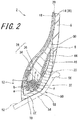
- FIG. 2 shows the bead 12 portion of the tire 2 in FIG. 1 .
- the up-down direction is the radial direction of the tire 2
- the right-left direction is the axial direction of the tire 2
- the direction perpendicular to the drawing sheet is the circumferential direction of the tire 2.
- FIG. 2 also shows a rim 50 on which the tire 2 is mounted.
- the rim 50 is a normal rim.
- the tire 2 is mounted onto the rim 50, and is inflated with air so that the internal pressure of the tire 2 is a normal internal pressure.
- normal rim means a rim that is specified by the standard with which the tire 2 complies.
- a normal rim may be a "standard rim” in the JATMA standards, a “design rim” in the TRA standards, or a “measuring rim” in the ETRTO standards.
- normal internal pressure means an internal pressure that is specified by the standard with which the tire 2 complies.
- a normal internal pressure may be a "maximum air pressure” in the JATMA standards, a “maximum value” recited in the "TIRE LOAD LIMITS AT VARIOUS COLD INFLATION PRESSURES" in the TRA standards, or an “inflation pressure” in the ETRTO standards.
- normal load means a load that is specified by the standard with which the tire 2 complies.
- a normal load may be a "maximum load capacity" in the JATMA standards, a “maximum value” recited in the "TIRE LOAD LIMITS AT VARIOUS COLD INFLATION PRESSURES" in the TRA standards, and a "load capacity” in the ETRTO standards.
- the dimensions and angles of the components of the tire 2 are measured in a state where the tire 2 is mounted on a normal rim and inflated with air to a normal internal pressure. During the measurement, no load is applied to the tire 2.
- the rim 50 includes a pair of fit portions 52.
- the bead 12 portions of the tire 2 are fitted with the fit portions 52, respectively.
- the fit portions 52 each include a rim seat 54 and a rim flange 56.
- the chafers 10 of the tire 2 are put on the rim seats 54, respectively.
- the clinches 8 of the tire 2 are brought into contact with the rim flanges 56, respectively.
- the rim seat 54 is inclined relative to the axial direction.
- the inclination angle of the rim seat 54 is typically set within the range of greater than or equal to 5° and not greater than 20°.
- the rim 50 the inclination angle of which is set to 15° is referred to also as a "15°-tapered rim”.
- the inclination angle is represented by the angle of the rim seat 54 relative to an imaginary line (axial direction) perpendicular to a rim center line (not shown).
- the body 34 of the core 28 is formed by arrangement of the wires 32 so that the body 34 has a hexagonal cross-section.
- the cross-section of the body 34 has six vertex portions.
- the vertex portions are indicated by reference characters "a”, "b", “c”, “d”, "e”, and "f".
- the vertex portion "b” is the axially inner end of the body 34.
- a diagonal line "be” connecting the vertex portion "b" and the vertex portion "e” is the longest of all the diagonal lines in the cross-section.
- the diagonal line "be” is referred to also as "major axis”.
- the major axis "be”, the major side "fa”, and the major side “cd” extend substantially in the axial direction.
- the cross-section of the body 34 is in the shape of a flattened hexagon which is elongated in the axial direction.
- the major side “fa” is a bottom side 58 of the cross-section of the core 28.
- the major side “fa” faces the rim seat 54 of the rim 50.
- the contour of the body 34 is shaped so that the major side “fa” is substantially parallel to the rim seat 54 in a state where the tire 2 is mounted on the rim 50.
- the difference between the angle of the major side "fa” relative to the axial direction and the inclination angle of the rim seat 54 is not greater than 5°, it is determined that the major side "fa” is substantially parallel to the rim seat 54.
- reference character CE indicates one end of a contact surface between the tire 2 and the rim 50. As shown in FIG. 2 , the tire 2 is not in contact with the rim 50 at a portion inward of the end CE in the axial direction. A gap is formed between the tire 2 and the rim 50 at the portion inward of the end CE in the axial direction.
- the position of the end CE of the contact surface substantially coincides with the position of the vertex portion "a" of the body 34 in the axial direction.
- the end CE of the contact surface is formed at a position corresponding to the vertex portion "a" of the body 34 in the axial direction in a state where the tire 2 is mounted on the rim 50 and inflated with air to a normal internal pressure.
- FIG. 3 shows details of the cross-section of the core 28.
- the core 28 includes the body 34 and the cover 36 which covers the body 34.
- the cover 36 is in the shape of a sheet. As shown in FIG. 3 , the cover 36 is wrapped one turn around the body 34. One end 60 portion of the cover 36 overlaps the other end 62 portion thereof. In the tire 2, one end 60 of the cover 36 may be joined to the other end 62 thereof without the one end 60 portion of the cover 36 overlapping the other end 62 portion thereof.
- the cover 36 is not wrapped two or more turns around the body 34. That is, in the tire 2, the number of turns the cover 36 is wrapped around the body 34 is greater than or equal to one and smaller than two.
- an overlap 64 of the cover 36 is formed between the vertex portion "c" and the vertex portion "d" of the body 34.
- the overlap 64 only needs to be formed within the range from the vertex portion "b” to the vertex portion "e” via the vertex portion "c” and the vertex portion "d".
- the overlap 64 is formed at any position within that range.
- a double-headed arrow LL indicates the length of the overlap 64 of the cover 36.
- the length LL is represented by the length from the one end 60 to the other end 62 of the cover 36 in the cross-section of the core 28 shown in FIG. 3 .
- the length LL of the overlap 64 is preferably greater than or equal to 3 mm and more preferably greater than or equal to 5 mm.
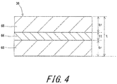
- FIG. 4 shows a cross-section of the cover 36 taken along the thickness direction thereof.
- the cover 36 includes a fabric 66 and a pair of sheets 68. That is, the cover 36 includes the fabric 66. As can be seen from FIG. 4 , the fabric 66 is interposed between the two sheets 68.
- each sheet 68 is made of a crosslinked rubber composition.
- each sheet 68 is a crosslinked rubber.
- the rubber composition for the sheet 68 is not particularly limited.
- a rubber composition having the same composition as that of the topping rubber for the carcass ply 38, the belt 16, or the fillers 22, may be used.
- FIG. 5 schematically shows the fabric 66 as a component of the cover 36. As shown in FIG. 2 , the carcass ply 38 is disposed outward of the cover 36. In FIG. 5 , carcass cords 70 included in the carcass ply 38 disposed outward of the cover 36 are indicated by broken lines.
- thick solid lines represent warp threads 72 and weft threads 74 included in the fabric 66 of the cover 36.
- the fabric 66 of the cover 36 includes multiple warp threads 72 aligned with each other, and multiple weft threads 74 aligned with each other.
- the fabric 66 is woven by crossing the warp threads 72 and the weft threads 74 alternately under and over each other.
- the fabric 66 is a plain weave fabric.
- the cover 36 includes a plain weave fabric in which the warp threads 72 and the weft threads 74 are interlaced together.
- the warp threads 72 and the weft threads 74 are each made of an organic fiber.
- the organic fiber include polyester fibers, nylon fibers, rayon fibers, polyethylene naphthalate fibers, and aramid fibers.
- the fabric 66 of the cover 36 is formed using the warp threads 72 and the weft threads 74 which are made of the same material.
- the fabric 66 may be formed using the warp threads 72 and the weft threads 74 which are made of different materials.
- At least the cover 36 of the core 28 is present between the body 34 of the core 28 and the carcass ply 38.
- At least the sheet 68 of the cover 36 and the topping rubber of the carcass ply 38 are present between the fabric 66 of the cover 36 and the carcass cords 70. That is, the rubber is present between the fabric 66 and the carcass cords 70.
- the rubber is more flexible than the fabric 66 and the carcass cords 70.
- an angle ⁇ is the angle of the warp thread 72 relative to the weft thread 74.
- the angle ⁇ is also the angle of the weft thread 74 relative to the warp thread 72.
- the angle ⁇ is an angle at which the warp thread 72 and the weft thread 74 intersect each other.
- the angle ⁇ influences flow of the rubber present between the carcass cords 70 and the core 28.
- a holding force exerted by the warp threads 72 on the weft threads 74, or a holding force exerted by the weft threads 74 on the warp threads 72 decreases, and therefore, the rubber may pass through the fabric 66.
- the intersection angle ⁇ is set so that the warp threads 72 and the weft threads 74 are not arranged approximately in parallel. Specifically, the angle ⁇ is greater than or equal to 45° and not greater than 125°.
- the intersection angle ⁇ is set to be greater than or equal to 45°, and therefore, even when excessive tension acts on the carcass cords 70, the plain weave fabric which is the fabric 66 inhibits flow of the rubber present between the carcass cords 70 and the core 28. Since the rubber is not dislodged and still remains between the carcass cords 70 and the core 28, the carcass cords 70 are prevented from coming into contact with the plain weave fabric or the body 34.
- the plain weave fabric prevents occurrence of damage such as breakage of the carcass cords 70.
- the angle ⁇ is preferably greater than or equal to 60° and more preferably greater than or equal to 90°.
- the plain weave fabric when the intersection angle ⁇ is set to be not greater than 125°, the plain weave fabric also exhibits the above effect. Specifically, even when excessive tension acts on the carcass cords 70, the plain weave fabric which is the fabric 66 inhibits flow of the rubber present between the carcass cords 70 and the core 28. Since the rubber is not dislodged and still remains between the carcass cords 70 and the core 28, the carcass cords 70 are prevented from coming into contact with the plain weave fabric or the body 34.
- the plain weave fabric prevents occurrence of damage such as breakage of the carcass cords 70. From this viewpoint, the angle ⁇ is more preferably not greater than 110°.
- the warp threads 72 are inclined relative to the carcass cords 70.
- an angle ⁇ p is the angle of the warp thread 72 relative to the carcass cord 70.
- the angle ⁇ p is the inclination angle of the warp thread 72 relative to the carcass cord 70.
- the inclination angle ⁇ p is set so that the warp threads 72 and the carcass cords 70 are not arranged approximately in parallel. Specifically, the angle ⁇ p is greater than or equal to 22.5° and not greater than 67.5°.
- the inclination angle ⁇ p is set to be greater than or equal to 22.5°, and therefore, even when excessive tension acts on the carcass cords 70, flow of the rubber present between the carcass cords 70 and the core 28 is effectively inhibited. Since the rubber is not dislodged and still remains between the carcass cords 70 and the core 28, the carcass cords 70 are prevented from coming into contact with the plain weave fabric or the body 34. As a result, occurrence of damage such as breakage of the carcass cords 70 is prevented. From this viewpoint, the angle ⁇ p is preferably greater than or equal to 30°. In the tire 2, the same effect is exhibited also when the inclination angle ⁇ p is set to be not greater than 67.5°.
- the angle ⁇ p is preferably not greater than 50°.
- the weft threads 74 are inclined relative to the carcass cords 70.
- the angle ⁇ t is the angle of the weft thread 74 relative to the carcass cord 70.
- the angle ⁇ t is the inclination angle of the weft thread 74 relative to the carcass cord 70.
- the inclination angle ⁇ t is set so that the weft threads 74 and the carcass cords 70 are not arranged approximately in parallel. Specifically, the angle ⁇ t is greater than or equal to 22.5° and not greater than 67.5°.
- the inclination angle ⁇ t is set to be greater than or equal to 22.5°, and therefore, even when excessive tension acts on the carcass cords 70, flow of the rubber present between the carcass cords 70 and the core 28 is effectively inhibited. Since the rubber is not dislodged and still remains between the carcass cords 70 and the core 28, the carcass cords 70 are prevented from coming into contact with the plain weave fabric or the body 34. As a result, occurrence of damage such as breakage of the carcass cords 70 is prevented. From this viewpoint, the angle ⁇ p is preferably greater than or equal to 30°. In the tire 2, the same effect is exhibited also when the inclination angle ⁇ t is set to be not greater than 67.5°.
- the angle ⁇ t is preferably not greater than 50°.
- the core 28 of the bead 12 includes the body 34 and the cover 36.
- the cover 36 includes the plain weave fabric.
- the intersection angle between the warp threads 72 and the weft threads 74 of the plain weave fabric is greater than or equal to 45° and not greater than 125°.
- the warp threads 72 are inclined relative to the carcass cords 70.
- the inclination angle ⁇ p is greater than or equal to 22.5° and not greater than 67.5°.
- the weft threads 74 are also inclined relative to the carcass cords 70.
- the inclination angle ⁇ t is greater than or equal to 22.5° and not greater than 67.5°.
- the plain weave fabric in which the warp threads 72 and the weft threads 74 sufficiently hold each other is used.
- the plain weave fabric is arranged so that neither the warp threads 72 nor the weft threads 74 are parallel to the carcass cords 70.
- a synergistic effect of these features allows the plain weave fabric to sufficiently inhibit flow of the rubber present between the carcass cords 70 and the core 28 even when excessive tension acts on the carcass cords 70. Since the rubber is not dislodged and still remains between the carcass cords 70 and the core 28, the carcass cords 70 are sufficiently prevented from coming into contact with the plain weave fabric or the body 34. In the tire 2, damage such as breakage of the carcass cords 70 is less likely to occur. In the tire 2, an improvement in durability is achieved.
- the body 34 has a flattened hexagonal cross-section which is elongated in the axial direction. Therefore, in the contour of the cross-section, the vertex portion "b" portion is slightly sharper than the vertex portion "a" portion. In particular, if the carcass cords 70 come into contact with the vertex portion "b" portion, breakage of the carcass cords 70 may be induced.
- the plain weave fabric inhibits flow of the rubber present between the carcass cords 70 and the core 28, and therefore, the carcass cords 70 are prevented from coming into contact with the plain weave fabric or the body 34.
- a double-headed arrow Dp indicates the interval between one warp thread 72 and another warp thread 72 adjacent to that warp thread 72.
- a double-headed arrow Dt indicates the interval between one weft thread 74 and another weft thread 74 adjacent to that weft thread 74.
- the multiple warp threads 72 are spaced at intervals Dp.
- the multiple weft threads 74 are spaced at intervals Dt.
- the interval Dp of the warp threads 72 is preferably greater than or equal to 0.5 mm and preferably not greater than 2.0 mm. If the interval Dp is set to be greater than or equal to 0.5 mm, the stiffness of the plain weave fabric which is the fabric 66 is suitably maintained without being excessive. In the tire 2, the cover 36 which includes the fabric 66 is easily wrapped around the body 34. For the tire 2, favorable productivity is maintained. From this viewpoint, the interval Dp is more preferably greater than or equal to 0.7 mm. If the interval Dp is set to be not greater than 2.0 mm, open spaces between the threads in the plain weave fabric are suitably maintained, and therefore, the plain weave fabric can effectively inhibit flow of the rubber present between the carcass cords 70 and the core 28.
- the carcass cords 70 are sufficiently prevented from coming into contact with the plain weave fabric or the body 34, and therefore, damage such as breakage of the carcass cords 70 is less likely to occur.
- the tire 2 is excellent in durability. From this viewpoint, the interval Dp is more preferably not greater than 1.3 mm.
- the interval Dt of the weft threads 74 is preferably greater than or equal to 0.5 mm and preferably not greater than 2.0 mm. If the interval Dt is set to be greater than or equal to 0.5 mm, the stiffness of the plain weave fabric which is the fabric 66 is suitably maintained without being excessive. In the tire 2, the cover 36 which includes the fabric 66 is easily wrapped around the body 34. For the tire 2, favorable productivity is maintained. From this viewpoint, the interval Dt is more preferably greater than or equal to 0.7 mm. If the interval Dt is set to be not greater than 2.0 mm, open spaces between the threads in the plain weave fabric are suitably maintained, and therefore, the plain weave fabric can effectively inhibit flow of the rubber present between the carcass cords 70 and the core 28.
- the carcass cords 70 are sufficiently prevented from coming into contact with the plain weave fabric or the body 34, and therefore, damage such as breakage of the carcass cords 70 is less likely to occur.
- the tire 2 is excellent in durability. From this viewpoint, the interval Dt is more preferably not greater than 1.3 mm.
- the warp threads 72 preferably have a strength Fp of greater than or equal to 20 N. If the strength Fp is set to be greater than or equal to 20 N, the warp threads 72 have a suitable stiffness. Even if excessive tension acts on the carcass cords 70 to apply force to the carcass cords 70 so that the carcass cords 70 are pressed against the fabric 66, the warp threads 72 are less likely to be broken.
- the plain weave fabric effectively inhibits flow of the rubber present between the carcass cords 70 and the core 28, and therefore, in the tire 2, the carcass cords 70 are sufficiently prevented from coming into contact with the plain weave fabric or the body 34. In the tire 2, damage such as breakage of the carcass cords 70 is less likely to occur.
- the strength Fp is more preferably greater than or equal to 30 N.
- the strength Fp of the warp threads 72 influences the stiffness of the fabric 66. From the viewpoint of allowing the cover 36 including the fabric 66 to be easily wrapped around the body 34 of the core 28, the strength Fp is preferably not greater than 100 N and more preferably not greater than 75 N.
- the strength Fp of the warp threads 72 is measured in compliance with the "tensile strength" in "JIS L1017".
- the "strength at break” which is measured to obtain the "tensile strength” is the “strength of a thread” in the present invention.
- the strength at break per warp thread 72 is represented as the strength Fp of the warp threads 72.
- a strength Ft of the weft threads 74 described below is measured in the same manner as for measuring the strength Fp of the warp threads 72.
- the strength Ft of the weft threads 74 is preferably greater than or equal to 20 N. If the strength Ft is set to be greater than or equal to 20 N, the weft threads 74 have a suitable stiffness. Even if excessive tension acts on the carcass cords 70 to apply force to the carcass cords 70 so that the carcass cords 70 are pressed against the fabric 66, the weft threads 74 are less likely to be broken.
- the plain weave fabric effectively inhibits flow of the rubber present between the carcass cords 70 and the core 28, and therefore, in the tire 2, the carcass cords 70 are sufficiently prevented from coming into contact with the plain weave fabric or the body 34. In the tire 2, damage such as breakage of the carcass cords 70 is less likely to occur.
- the strength Ft is more preferably greater than or equal to 30 N.
- the strength Ft of the weft threads 74 influences the stiffness of the fabric 66. From the viewpoint of allowing the cover 36 including the fabric 66 to be easily wrapped around the body 34 of the core 28, the strength Ft is preferably not greater than 100 N and more preferably not greater than 75 N.
- the warp threads 72 preferably have a fineness of greater than or equal to 300 dtex. If the fineness is set to be greater than or equal to 300 dtex, the warp threads 72 have a suitable stiffness. Even if excessive tension acts on the carcass cords 70 to apply force to the carcass cords 70 so that the carcass cords 70 are pressed against the fabric 66, the warp threads 72 are less likely to be broken.
- the plain weave fabric effectively inhibits flow of the rubber present between the carcass cords 70 and the core 28, and therefore, in the tire 2, the carcass cords 70 are sufficiently prevented from coming into contact with the plain weave fabric or the body 34. In the tire 2, damage such as breakage of the carcass cords 70 is less likely to occur.
- the fineness of the warp threads 72 influences the stiffness of the fabric 66. From the viewpoint of allowing the cover 36 including the fabric 66 to be easily wrapped around the body 34 of the core 28, the fineness is preferably not greater than 1670 dtex.
- the weft threads 74 preferably have a fineness of greater than or equal to 300 dtex. If the fineness is set to be greater than or equal to 300 dtex, the weft threads 74 have a suitable stiffness. Even if excessive tension acts on the carcass cords 70 to apply force to the carcass cords 70 so that the carcass cords 70 are pressed against the fabric 66, the weft threads 74 are less likely to be broken.
- the plain weave fabric effectively inhibits flow of the rubber present between the carcass cords 70 and the core 28, and therefore, in the tire 2, the carcass cords 70 are sufficiently prevented from coming into contact with the plain weave fabric or the body 34.
- the fineness of the weft threads 74 influences the stiffness of the fabric 66. From the viewpoint of allowing the cover 36 including the fabric 66 to be easily wrapped around the body 34 of the core 28, the fineness is preferably not greater than 1670 dtex.
- a double-headed arrow “t” indicates the thickness of the cover 36.
- a double-headed arrow “tt” indicates the thickness of the fabric 66 which is a part of the cover 36.
- a double-headed arrow “tr” indicates the thickness of each sheet 68 layered over the fabric 66.
- the thickness "t” of the cover 36 is represented by the sum (tt + 2tr) of the thickness "tt” of the fabric 66 and the thicknesses "tr" of the two sheets 68 disposed on the respective sides of the fabric 66.
- the thickness "tt” of the fabric 66 is within the range of 0.1 mm to 0.8 mm.
- the thickness "tr" of each sheet 68 is within the range of 0.1 mm to 0.5 mm.
- the thickness "t" of the cover 36 including a combination of the fabric 66 and the two sheets 68 is preferably greater than or equal to 0.6 mm and preferably not greater than 1.2 mm. If the thickness "t" is set to be greater than or equal to 0.6 mm, a suitable amount of the rubber present between the carcass cords 70 and the core 28 is ensured, and therefore, the carcass cords 70 are prevented from coming into contact with the plain weave fabric or the body 34. In the tire 2, damage such as breakage of the carcass cords 70 is less likely to occur. The tire 2 is excellent in durability. If the thickness "t" is set to be not greater than 1.2 mm, the stiffness of the cover 36 is suitably maintained. In the tire 2, the cover 36 is easily wrapped around the body 34 of the core 28. For the tire 2, favorable productivity is maintained.
- Example 1 A tire as shown in FIGS. 1 to 5 was produced.
- the size of the tire was 12.00R20.
- Example 1 a plain weave fabric made of a nylon fiber was used as the fabric of the cover. In the plain weave fabric, the warp threads and the weft threads had a fineness of 490 dtex. Specifications of Example 1 are as indicated in Table 1 below.
- Tires of Examples 2 and 3 and Comparative Examples 1 and 2 were obtained in the same manner as for Example 1 except that the intersection angle ⁇ between the warp threads and the weft threads, the inclination angle ⁇ p of the warp threads relative to the carcass cords, and the inclination angle ⁇ t of the weft threads relative to the carcass cords were as indicated in Table 1 below.
- Tires of Examples 4 and 5 and Comparative Examples 3 and 4 were obtained in the same manner as for Example 1 except that the intersection angle ⁇ and the inclination angle ⁇ p were as indicated in Table 2 below.
- Tires of Examples 6 and 7 and Comparative Examples 5 and 6 were obtained in the same manner as for Example 1 except that the intersection angle ⁇ and the inclination angle ⁇ t were as indicated in Table 3 below.
- Tires of Examples 8 to 11 were obtained in the same manner as for Example 1 except that the interval Dp of the warp threads and the interval Dt of the weft threads were as indicated in Table 4 below.
- Tires of Examples 12 and 13 were obtained in the same manner as for Example 1 except that the strength Fp of the warp threads and the strength Ft of the weft threads were as indicated in Table 4 below.
- Tires of Examples 14 to 17 were obtained in the same manner as for Example 1 except that the thickness "t" of the cover was as indicated in Table 5 below.
- the tire was mounted to a drum type tire testing machine, and a vertical load which was 300% of a normal load was applied to the tire.
- Running with the tire on a drum having a diameter of 1.7 m at a speed of 20 km/h was performed. After the running was performed for 150 hours, the thickness from the carcass cords to the body of the core in the tire was measured.
- the results are indicated as indexes in Tables 1 to 5 below. The greater the value of the index is, the more sufficiently the rubber is present between the carcass cords and the core, and the less likely breakage of the carcass cords is to occur, which is more preferable.
- the technology relating to the core described above is applicable to various tires.
Landscapes
- Engineering & Computer Science (AREA)
- Mechanical Engineering (AREA)
- Tires In General (AREA)
Applications Claiming Priority (1)
| Application Number | Priority Date | Filing Date | Title |
|---|---|---|---|
| JP2016087759A JP6668916B2 (ja) | 2016-04-26 | 2016-04-26 | 空気入りタイヤ |
Publications (2)
| Publication Number | Publication Date |
|---|---|
| EP3238962A1 true EP3238962A1 (de) | 2017-11-01 |
| EP3238962B1 EP3238962B1 (de) | 2018-06-13 |
Family
ID=58549070
Family Applications (1)
| Application Number | Title | Priority Date | Filing Date |
|---|---|---|---|
| EP17166839.5A Not-in-force EP3238962B1 (de) | 2016-04-26 | 2017-04-18 | Luftreifen |
Country Status (4)
| Country | Link |
|---|---|
| US (1) | US10479144B2 (de) |
| EP (1) | EP3238962B1 (de) |
| JP (1) | JP6668916B2 (de) |
| CN (1) | CN107310334B (de) |
Cited By (1)
| Publication number | Priority date | Publication date | Assignee | Title |
|---|---|---|---|---|
| EP4257372A1 (de) * | 2022-03-30 | 2023-10-11 | Sumitomo Rubber Industries, Ltd. | Reifen |
Families Citing this family (3)
| Publication number | Priority date | Publication date | Assignee | Title |
|---|---|---|---|---|
| JP7154947B2 (ja) * | 2018-10-26 | 2022-10-18 | Toyo Tire株式会社 | 空気入りタイヤの製造方法及びビード部材の収納ホルダー |
| JP7138079B2 (ja) * | 2019-05-17 | 2022-09-15 | Toyo Tire株式会社 | ビードコア被覆方法及びビードコア被覆装置 |
| JP7302400B2 (ja) * | 2019-09-11 | 2023-07-04 | 住友ゴム工業株式会社 | 重荷重用空気入りタイヤ |
Citations (6)
| Publication number | Priority date | Publication date | Assignee | Title |
|---|---|---|---|---|
| DE4424279A1 (de) * | 1994-07-09 | 1996-01-11 | Uniroyal Englebert Gmbh | Bandage und Verfahren zur Bandage von festigkeitsgebenden Schichten eines Reifens |
| JPH11291724A (ja) | 1998-04-10 | 1999-10-26 | Sumitomo Rubber Ind Ltd | 空気入りタイヤ |
| US6273162B1 (en) | 1998-04-10 | 2001-08-14 | Sumitomo Rubber Industries, Ltd. | Pneumatic tire with specified bead portion |
| JP2005170062A (ja) * | 2003-12-05 | 2005-06-30 | Bridgestone Corp | 空気入りタイヤ |
| EP1657081A1 (de) * | 2004-11-12 | 2006-05-17 | Sumtiomo Rubber Industries Ltd | Luftreifen mit Kabelkern |
| JP2013018457A (ja) * | 2011-07-14 | 2013-01-31 | Yokohama Rubber Co Ltd:The | 空気入りタイヤおよび空気入りタイヤ補強用平織物 |
Family Cites Families (9)
| Publication number | Priority date | Publication date | Assignee | Title |
|---|---|---|---|---|
| JPS62121039A (ja) * | 1985-11-21 | 1987-06-02 | Bridgestone Corp | タイヤビ−ドコア用カバ−テ−プ |
| JP3096925B2 (ja) * | 1991-07-22 | 2000-10-10 | 横浜ゴム株式会社 | 空気入りラジアルタイヤ |
| JP3848771B2 (ja) * | 1998-01-09 | 2006-11-22 | 横浜ゴム株式会社 | 空気入りタイヤ |
| JP3441720B2 (ja) * | 2000-06-05 | 2003-09-02 | 住友ゴム工業株式会社 | 空気入りタイヤ |
| JP4267892B2 (ja) * | 2002-10-21 | 2009-05-27 | 株式会社ブリヂストン | スチールラジアルタイヤ及びその製造方法 |
| JP4393759B2 (ja) * | 2002-11-26 | 2010-01-06 | 不二精工株式会社 | 空気入りラジアルタイヤ及びそのビード |
| JP4996112B2 (ja) * | 2006-03-01 | 2012-08-08 | 株式会社ブリヂストン | 空気入りラジアルタイヤ |
| JP4934178B2 (ja) * | 2009-09-04 | 2012-05-16 | 住友ゴム工業株式会社 | 重荷重用空気入りタイヤ |
| JP2012040900A (ja) * | 2010-08-16 | 2012-03-01 | Bridgestone Corp | タイヤ |
-
2016
- 2016-04-26 JP JP2016087759A patent/JP6668916B2/ja not_active Expired - Fee Related
-
2017
- 2017-04-13 CN CN201710238555.3A patent/CN107310334B/zh not_active Expired - Fee Related
- 2017-04-18 EP EP17166839.5A patent/EP3238962B1/de not_active Not-in-force
- 2017-04-25 US US15/496,870 patent/US10479144B2/en active Active
Patent Citations (6)
| Publication number | Priority date | Publication date | Assignee | Title |
|---|---|---|---|---|
| DE4424279A1 (de) * | 1994-07-09 | 1996-01-11 | Uniroyal Englebert Gmbh | Bandage und Verfahren zur Bandage von festigkeitsgebenden Schichten eines Reifens |
| JPH11291724A (ja) | 1998-04-10 | 1999-10-26 | Sumitomo Rubber Ind Ltd | 空気入りタイヤ |
| US6273162B1 (en) | 1998-04-10 | 2001-08-14 | Sumitomo Rubber Industries, Ltd. | Pneumatic tire with specified bead portion |
| JP2005170062A (ja) * | 2003-12-05 | 2005-06-30 | Bridgestone Corp | 空気入りタイヤ |
| EP1657081A1 (de) * | 2004-11-12 | 2006-05-17 | Sumtiomo Rubber Industries Ltd | Luftreifen mit Kabelkern |
| JP2013018457A (ja) * | 2011-07-14 | 2013-01-31 | Yokohama Rubber Co Ltd:The | 空気入りタイヤおよび空気入りタイヤ補強用平織物 |
Cited By (1)
| Publication number | Priority date | Publication date | Assignee | Title |
|---|---|---|---|---|
| EP4257372A1 (de) * | 2022-03-30 | 2023-10-11 | Sumitomo Rubber Industries, Ltd. | Reifen |
Also Published As
| Publication number | Publication date |
|---|---|
| CN107310334B (zh) | 2020-09-29 |
| US20170305205A1 (en) | 2017-10-26 |
| EP3238962B1 (de) | 2018-06-13 |
| CN107310334A (zh) | 2017-11-03 |
| JP6668916B2 (ja) | 2020-03-18 |
| JP2017196955A (ja) | 2017-11-02 |
| US10479144B2 (en) | 2019-11-19 |
Similar Documents
| Publication | Publication Date | Title |
|---|---|---|
| US11618283B2 (en) | Pneumatic tire | |
| EP3127717B1 (de) | Luftreifen | |
| EP2676808B1 (de) | Luftreifen | |
| EP3093164B1 (de) | Luftreifen | |
| US10589577B2 (en) | Heavy-duty pneumatic tire | |
| EP3210800A2 (de) | Luftreifen | |
| US9272582B2 (en) | Pneumatic tire | |
| EP3231634B1 (de) | Luftreifen | |
| EP3238962B1 (de) | Luftreifen | |
| EP3281805B1 (de) | Luftreifen | |
| US10821785B2 (en) | Pneumatic tire | |
| EP3135506B1 (de) | Luftreifen | |
| EP3045327A1 (de) | Reifen | |
| EP3235664B1 (de) | Luftreifen | |
| EP3061630B1 (de) | Luftreifen | |
| US11279179B2 (en) | Pneumatic tire | |
| EP3202599A1 (de) | Luftreifen | |
| US11951777B2 (en) | Tire | |
| EP4321351A2 (de) | Reifen | |
| JP2016041526A (ja) | 空気入りタイヤ |
Legal Events
| Date | Code | Title | Description |
|---|---|---|---|
| PUAI | Public reference made under article 153(3) epc to a published international application that has entered the european phase |
Free format text: ORIGINAL CODE: 0009012 |
|
| STAA | Information on the status of an ep patent application or granted ep patent |
Free format text: STATUS: THE APPLICATION HAS BEEN PUBLISHED |
|
| AK | Designated contracting states |
Kind code of ref document: A1 Designated state(s): AL AT BE BG CH CY CZ DE DK EE ES FI FR GB GR HR HU IE IS IT LI LT LU LV MC MK MT NL NO PL PT RO RS SE SI SK SM TR |
|
| AX | Request for extension of the european patent |
Extension state: BA ME |
|
| STAA | Information on the status of an ep patent application or granted ep patent |
Free format text: STATUS: REQUEST FOR EXAMINATION WAS MADE |
|
| 17P | Request for examination filed |
Effective date: 20171212 |
|
| RBV | Designated contracting states (corrected) |
Designated state(s): AL AT BE BG CH CY CZ DE DK EE ES FI FR GB GR HR HU IE IS IT LI LT LU LV MC MK MT NL NO PL PT RO RS SE SI SK SM TR |
|
| GRAP | Despatch of communication of intention to grant a patent |
Free format text: ORIGINAL CODE: EPIDOSNIGR1 |
|
| STAA | Information on the status of an ep patent application or granted ep patent |
Free format text: STATUS: GRANT OF PATENT IS INTENDED |
|
| RIC1 | Information provided on ipc code assigned before grant |
Ipc: B29D 30/50 20060101ALN20180116BHEP Ipc: B29D 30/48 20060101ALN20180116BHEP Ipc: B60C 15/04 20060101AFI20180116BHEP |
|
| INTG | Intention to grant announced |
Effective date: 20180209 |
|
| GRAS | Grant fee paid |
Free format text: ORIGINAL CODE: EPIDOSNIGR3 |
|
| GRAA | (expected) grant |
Free format text: ORIGINAL CODE: 0009210 |
|
| STAA | Information on the status of an ep patent application or granted ep patent |
Free format text: STATUS: THE PATENT HAS BEEN GRANTED |
|
| AK | Designated contracting states |
Kind code of ref document: B1 Designated state(s): AL AT BE BG CH CY CZ DE DK EE ES FI FR GB GR HR HU IE IS IT LI LT LU LV MC MK MT NL NO PL PT RO RS SE SI SK SM TR |
|
| REG | Reference to a national code |
Ref country code: GB Ref legal event code: FG4D |
|
| REG | Reference to a national code |
Ref country code: CH Ref legal event code: EP Ref country code: AT Ref legal event code: REF Ref document number: 1008095 Country of ref document: AT Kind code of ref document: T Effective date: 20180615 |
|
| REG | Reference to a national code |
Ref country code: IE Ref legal event code: FG4D |
|
| REG | Reference to a national code |
Ref country code: DE Ref legal event code: R096 Ref document number: 602017000101 Country of ref document: DE |
|
| REG | Reference to a national code |
Ref country code: NL Ref legal event code: MP Effective date: 20180613 |
|
| REG | Reference to a national code |
Ref country code: LT Ref legal event code: MG4D |
|
| PG25 | Lapsed in a contracting state [announced via postgrant information from national office to epo] |
Ref country code: BG Free format text: LAPSE BECAUSE OF FAILURE TO SUBMIT A TRANSLATION OF THE DESCRIPTION OR TO PAY THE FEE WITHIN THE PRESCRIBED TIME-LIMIT Effective date: 20180913 Ref country code: NO Free format text: LAPSE BECAUSE OF FAILURE TO SUBMIT A TRANSLATION OF THE DESCRIPTION OR TO PAY THE FEE WITHIN THE PRESCRIBED TIME-LIMIT Effective date: 20180913 Ref country code: FI Free format text: LAPSE BECAUSE OF FAILURE TO SUBMIT A TRANSLATION OF THE DESCRIPTION OR TO PAY THE FEE WITHIN THE PRESCRIBED TIME-LIMIT Effective date: 20180613 Ref country code: LT Free format text: LAPSE BECAUSE OF FAILURE TO SUBMIT A TRANSLATION OF THE DESCRIPTION OR TO PAY THE FEE WITHIN THE PRESCRIBED TIME-LIMIT Effective date: 20180613 Ref country code: CY Free format text: LAPSE BECAUSE OF FAILURE TO SUBMIT A TRANSLATION OF THE DESCRIPTION OR TO PAY THE FEE WITHIN THE PRESCRIBED TIME-LIMIT Effective date: 20180613 Ref country code: SE Free format text: LAPSE BECAUSE OF FAILURE TO SUBMIT A TRANSLATION OF THE DESCRIPTION OR TO PAY THE FEE WITHIN THE PRESCRIBED TIME-LIMIT Effective date: 20180613 |
|
| PG25 | Lapsed in a contracting state [announced via postgrant information from national office to epo] |
Ref country code: HR Free format text: LAPSE BECAUSE OF FAILURE TO SUBMIT A TRANSLATION OF THE DESCRIPTION OR TO PAY THE FEE WITHIN THE PRESCRIBED TIME-LIMIT Effective date: 20180613 Ref country code: RS Free format text: LAPSE BECAUSE OF FAILURE TO SUBMIT A TRANSLATION OF THE DESCRIPTION OR TO PAY THE FEE WITHIN THE PRESCRIBED TIME-LIMIT Effective date: 20180613 Ref country code: GR Free format text: LAPSE BECAUSE OF FAILURE TO SUBMIT A TRANSLATION OF THE DESCRIPTION OR TO PAY THE FEE WITHIN THE PRESCRIBED TIME-LIMIT Effective date: 20180914 Ref country code: LV Free format text: LAPSE BECAUSE OF FAILURE TO SUBMIT A TRANSLATION OF THE DESCRIPTION OR TO PAY THE FEE WITHIN THE PRESCRIBED TIME-LIMIT Effective date: 20180613 |
|
| REG | Reference to a national code |
Ref country code: AT Ref legal event code: MK05 Ref document number: 1008095 Country of ref document: AT Kind code of ref document: T Effective date: 20180613 |
|
| PG25 | Lapsed in a contracting state [announced via postgrant information from national office to epo] |
Ref country code: NL Free format text: LAPSE BECAUSE OF FAILURE TO SUBMIT A TRANSLATION OF THE DESCRIPTION OR TO PAY THE FEE WITHIN THE PRESCRIBED TIME-LIMIT Effective date: 20180613 |
|
| PG25 | Lapsed in a contracting state [announced via postgrant information from national office to epo] |
Ref country code: SK Free format text: LAPSE BECAUSE OF FAILURE TO SUBMIT A TRANSLATION OF THE DESCRIPTION OR TO PAY THE FEE WITHIN THE PRESCRIBED TIME-LIMIT Effective date: 20180613 Ref country code: RO Free format text: LAPSE BECAUSE OF FAILURE TO SUBMIT A TRANSLATION OF THE DESCRIPTION OR TO PAY THE FEE WITHIN THE PRESCRIBED TIME-LIMIT Effective date: 20180613 Ref country code: CZ Free format text: LAPSE BECAUSE OF FAILURE TO SUBMIT A TRANSLATION OF THE DESCRIPTION OR TO PAY THE FEE WITHIN THE PRESCRIBED TIME-LIMIT Effective date: 20180613 Ref country code: IS Free format text: LAPSE BECAUSE OF FAILURE TO SUBMIT A TRANSLATION OF THE DESCRIPTION OR TO PAY THE FEE WITHIN THE PRESCRIBED TIME-LIMIT Effective date: 20181013 Ref country code: PL Free format text: LAPSE BECAUSE OF FAILURE TO SUBMIT A TRANSLATION OF THE DESCRIPTION OR TO PAY THE FEE WITHIN THE PRESCRIBED TIME-LIMIT Effective date: 20180613 Ref country code: EE Free format text: LAPSE BECAUSE OF FAILURE TO SUBMIT A TRANSLATION OF THE DESCRIPTION OR TO PAY THE FEE WITHIN THE PRESCRIBED TIME-LIMIT Effective date: 20180613 Ref country code: AT Free format text: LAPSE BECAUSE OF FAILURE TO SUBMIT A TRANSLATION OF THE DESCRIPTION OR TO PAY THE FEE WITHIN THE PRESCRIBED TIME-LIMIT Effective date: 20180613 |
|
| PG25 | Lapsed in a contracting state [announced via postgrant information from national office to epo] |
Ref country code: SM Free format text: LAPSE BECAUSE OF FAILURE TO SUBMIT A TRANSLATION OF THE DESCRIPTION OR TO PAY THE FEE WITHIN THE PRESCRIBED TIME-LIMIT Effective date: 20180613 Ref country code: IT Free format text: LAPSE BECAUSE OF FAILURE TO SUBMIT A TRANSLATION OF THE DESCRIPTION OR TO PAY THE FEE WITHIN THE PRESCRIBED TIME-LIMIT Effective date: 20180613 Ref country code: ES Free format text: LAPSE BECAUSE OF FAILURE TO SUBMIT A TRANSLATION OF THE DESCRIPTION OR TO PAY THE FEE WITHIN THE PRESCRIBED TIME-LIMIT Effective date: 20180613 |
|
| REG | Reference to a national code |
Ref country code: DE Ref legal event code: R097 Ref document number: 602017000101 Country of ref document: DE |
|
| PLBE | No opposition filed within time limit |
Free format text: ORIGINAL CODE: 0009261 |
|
| STAA | Information on the status of an ep patent application or granted ep patent |
Free format text: STATUS: NO OPPOSITION FILED WITHIN TIME LIMIT |
|
| 26N | No opposition filed |
Effective date: 20190314 |
|
| PG25 | Lapsed in a contracting state [announced via postgrant information from national office to epo] |
Ref country code: DK Free format text: LAPSE BECAUSE OF FAILURE TO SUBMIT A TRANSLATION OF THE DESCRIPTION OR TO PAY THE FEE WITHIN THE PRESCRIBED TIME-LIMIT Effective date: 20180613 |
|
| PG25 | Lapsed in a contracting state [announced via postgrant information from national office to epo] |
Ref country code: AL Free format text: LAPSE BECAUSE OF FAILURE TO SUBMIT A TRANSLATION OF THE DESCRIPTION OR TO PAY THE FEE WITHIN THE PRESCRIBED TIME-LIMIT Effective date: 20180613 |
|
| REG | Reference to a national code |
Ref country code: BE Ref legal event code: MM Effective date: 20190430 |
|
| PG25 | Lapsed in a contracting state [announced via postgrant information from national office to epo] |
Ref country code: MC Free format text: LAPSE BECAUSE OF FAILURE TO SUBMIT A TRANSLATION OF THE DESCRIPTION OR TO PAY THE FEE WITHIN THE PRESCRIBED TIME-LIMIT Effective date: 20180613 Ref country code: LU Free format text: LAPSE BECAUSE OF NON-PAYMENT OF DUE FEES Effective date: 20190418 |
|
| PG25 | Lapsed in a contracting state [announced via postgrant information from national office to epo] |
Ref country code: BE Free format text: LAPSE BECAUSE OF NON-PAYMENT OF DUE FEES Effective date: 20190430 |
|
| PG25 | Lapsed in a contracting state [announced via postgrant information from national office to epo] |
Ref country code: TR Free format text: LAPSE BECAUSE OF FAILURE TO SUBMIT A TRANSLATION OF THE DESCRIPTION OR TO PAY THE FEE WITHIN THE PRESCRIBED TIME-LIMIT Effective date: 20180613 |
|
| PG25 | Lapsed in a contracting state [announced via postgrant information from national office to epo] |
Ref country code: IE Free format text: LAPSE BECAUSE OF NON-PAYMENT OF DUE FEES Effective date: 20190418 |
|
| PG25 | Lapsed in a contracting state [announced via postgrant information from national office to epo] |
Ref country code: PT Free format text: LAPSE BECAUSE OF FAILURE TO SUBMIT A TRANSLATION OF THE DESCRIPTION OR TO PAY THE FEE WITHIN THE PRESCRIBED TIME-LIMIT Effective date: 20181015 |
|
| REG | Reference to a national code |
Ref country code: CH Ref legal event code: PL |
|
| PG25 | Lapsed in a contracting state [announced via postgrant information from national office to epo] |
Ref country code: LI Free format text: LAPSE BECAUSE OF NON-PAYMENT OF DUE FEES Effective date: 20200430 Ref country code: CH Free format text: LAPSE BECAUSE OF NON-PAYMENT OF DUE FEES Effective date: 20200430 |
|
| PG25 | Lapsed in a contracting state [announced via postgrant information from national office to epo] |
Ref country code: MT Free format text: LAPSE BECAUSE OF FAILURE TO SUBMIT A TRANSLATION OF THE DESCRIPTION OR TO PAY THE FEE WITHIN THE PRESCRIBED TIME-LIMIT Effective date: 20180613 Ref country code: HU Free format text: LAPSE BECAUSE OF FAILURE TO SUBMIT A TRANSLATION OF THE DESCRIPTION OR TO PAY THE FEE WITHIN THE PRESCRIBED TIME-LIMIT; INVALID AB INITIO Effective date: 20170418 |
|
| PG25 | Lapsed in a contracting state [announced via postgrant information from national office to epo] |
Ref country code: SI Free format text: LAPSE BECAUSE OF FAILURE TO SUBMIT A TRANSLATION OF THE DESCRIPTION OR TO PAY THE FEE WITHIN THE PRESCRIBED TIME-LIMIT Effective date: 20180613 |
|
| GBPC | Gb: european patent ceased through non-payment of renewal fee |
Effective date: 20210418 |
|
| PG25 | Lapsed in a contracting state [announced via postgrant information from national office to epo] |
Ref country code: GB Free format text: LAPSE BECAUSE OF NON-PAYMENT OF DUE FEES Effective date: 20210418 |
|
| PG25 | Lapsed in a contracting state [announced via postgrant information from national office to epo] |
Ref country code: MK Free format text: LAPSE BECAUSE OF FAILURE TO SUBMIT A TRANSLATION OF THE DESCRIPTION OR TO PAY THE FEE WITHIN THE PRESCRIBED TIME-LIMIT Effective date: 20180613 |
|
| P01 | Opt-out of the competence of the unified patent court (upc) registered |
Effective date: 20230510 |
|
| PGFP | Annual fee paid to national office [announced via postgrant information from national office to epo] |
Ref country code: FR Payment date: 20240308 Year of fee payment: 8 |
|
| PGFP | Annual fee paid to national office [announced via postgrant information from national office to epo] |
Ref country code: DE Payment date: 20240227 Year of fee payment: 8 |
|
| REG | Reference to a national code |
Ref country code: DE Ref legal event code: R119 Ref document number: 602017000101 Country of ref document: DE |
|
| PG25 | Lapsed in a contracting state [announced via postgrant information from national office to epo] |
Ref country code: DE Free format text: LAPSE BECAUSE OF NON-PAYMENT OF DUE FEES Effective date: 20251104 |
|
| PG25 | Lapsed in a contracting state [announced via postgrant information from national office to epo] |
Ref country code: FR Free format text: LAPSE BECAUSE OF NON-PAYMENT OF DUE FEES Effective date: 20250430 |