EP3238979A1 - Chargeur intégré pour véhicules et son procédé de fabrication - Google Patents
Chargeur intégré pour véhicules et son procédé de fabrication Download PDFInfo
- Publication number
- EP3238979A1 EP3238979A1 EP17167717.2A EP17167717A EP3238979A1 EP 3238979 A1 EP3238979 A1 EP 3238979A1 EP 17167717 A EP17167717 A EP 17167717A EP 3238979 A1 EP3238979 A1 EP 3238979A1
- Authority
- EP
- European Patent Office
- Prior art keywords
- coupled
- voltage converter
- converter assembly
- electromechanical device
- bus
- Prior art date
- Legal status (The legal status is an assumption and is not a legal conclusion. Google has not performed a legal analysis and makes no representation as to the accuracy of the status listed.)
- Granted
Links
Images

Classifications
-
- B—PERFORMING OPERATIONS; TRANSPORTING
- B60—VEHICLES IN GENERAL
- B60L—PROPULSION OF ELECTRICALLY-PROPELLED VEHICLES; SUPPLYING ELECTRIC POWER FOR AUXILIARY EQUIPMENT OF ELECTRICALLY-PROPELLED VEHICLES; ELECTRODYNAMIC BRAKE SYSTEMS FOR VEHICLES IN GENERAL; MAGNETIC SUSPENSION OR LEVITATION FOR VEHICLES; MONITORING OPERATING VARIABLES OF ELECTRICALLY-PROPELLED VEHICLES; ELECTRIC SAFETY DEVICES FOR ELECTRICALLY-PROPELLED VEHICLES
- B60L50/00—Electric propulsion with power supplied within the vehicle
- B60L50/50—Electric propulsion with power supplied within the vehicle using propulsion power supplied by batteries or fuel cells
- B60L50/60—Electric propulsion with power supplied within the vehicle using propulsion power supplied by batteries or fuel cells using power supplied by batteries
-
- B—PERFORMING OPERATIONS; TRANSPORTING
- B60—VEHICLES IN GENERAL
- B60K—ARRANGEMENT OR MOUNTING OF PROPULSION UNITS OR OF TRANSMISSIONS IN VEHICLES; ARRANGEMENT OR MOUNTING OF PLURAL DIVERSE PRIME-MOVERS IN VEHICLES; AUXILIARY DRIVES FOR VEHICLES; INSTRUMENTATION OR DASHBOARDS FOR VEHICLES; ARRANGEMENTS IN CONNECTION WITH COOLING, AIR INTAKE, GAS EXHAUST OR FUEL SUPPLY OF PROPULSION UNITS IN VEHICLES
- B60K6/00—Arrangement or mounting of plural diverse prime-movers for mutual or common propulsion, e.g. hybrid propulsion systems comprising electric motors and internal combustion engines
- B60K6/20—Arrangement or mounting of plural diverse prime-movers for mutual or common propulsion, e.g. hybrid propulsion systems comprising electric motors and internal combustion engines the prime-movers consisting of electric motors and internal combustion engines, e.g. HEVs
- B60K6/22—Arrangement or mounting of plural diverse prime-movers for mutual or common propulsion, e.g. hybrid propulsion systems comprising electric motors and internal combustion engines the prime-movers consisting of electric motors and internal combustion engines, e.g. HEVs characterised by apparatus, components or means specially adapted for HEVs
- B60K6/26—Arrangement or mounting of plural diverse prime-movers for mutual or common propulsion, e.g. hybrid propulsion systems comprising electric motors and internal combustion engines the prime-movers consisting of electric motors and internal combustion engines, e.g. HEVs characterised by apparatus, components or means specially adapted for HEVs characterised by the motors or the generators
-
- B—PERFORMING OPERATIONS; TRANSPORTING
- B60—VEHICLES IN GENERAL
- B60L—PROPULSION OF ELECTRICALLY-PROPELLED VEHICLES; SUPPLYING ELECTRIC POWER FOR AUXILIARY EQUIPMENT OF ELECTRICALLY-PROPELLED VEHICLES; ELECTRODYNAMIC BRAKE SYSTEMS FOR VEHICLES IN GENERAL; MAGNETIC SUSPENSION OR LEVITATION FOR VEHICLES; MONITORING OPERATING VARIABLES OF ELECTRICALLY-PROPELLED VEHICLES; ELECTRIC SAFETY DEVICES FOR ELECTRICALLY-PROPELLED VEHICLES
- B60L50/00—Electric propulsion with power supplied within the vehicle
- B60L50/50—Electric propulsion with power supplied within the vehicle using propulsion power supplied by batteries or fuel cells
- B60L50/51—Electric propulsion with power supplied within the vehicle using propulsion power supplied by batteries or fuel cells characterised by AC-motors
-
- B—PERFORMING OPERATIONS; TRANSPORTING
- B60—VEHICLES IN GENERAL
- B60L—PROPULSION OF ELECTRICALLY-PROPELLED VEHICLES; SUPPLYING ELECTRIC POWER FOR AUXILIARY EQUIPMENT OF ELECTRICALLY-PROPELLED VEHICLES; ELECTRODYNAMIC BRAKE SYSTEMS FOR VEHICLES IN GENERAL; MAGNETIC SUSPENSION OR LEVITATION FOR VEHICLES; MONITORING OPERATING VARIABLES OF ELECTRICALLY-PROPELLED VEHICLES; ELECTRIC SAFETY DEVICES FOR ELECTRICALLY-PROPELLED VEHICLES
- B60L53/00—Methods of charging batteries, specially adapted for electric vehicles; Charging stations or on-board charging equipment therefor; Exchange of energy storage elements in electric vehicles
- B60L53/20—Methods of charging batteries, specially adapted for electric vehicles; Charging stations or on-board charging equipment therefor; Exchange of energy storage elements in electric vehicles characterised by converters located in the vehicle
- B60L53/22—Constructional details or arrangements of charging converters specially adapted for charging electric vehicles
-
- B—PERFORMING OPERATIONS; TRANSPORTING
- B60—VEHICLES IN GENERAL
- B60L—PROPULSION OF ELECTRICALLY-PROPELLED VEHICLES; SUPPLYING ELECTRIC POWER FOR AUXILIARY EQUIPMENT OF ELECTRICALLY-PROPELLED VEHICLES; ELECTRODYNAMIC BRAKE SYSTEMS FOR VEHICLES IN GENERAL; MAGNETIC SUSPENSION OR LEVITATION FOR VEHICLES; MONITORING OPERATING VARIABLES OF ELECTRICALLY-PROPELLED VEHICLES; ELECTRIC SAFETY DEVICES FOR ELECTRICALLY-PROPELLED VEHICLES
- B60L53/00—Methods of charging batteries, specially adapted for electric vehicles; Charging stations or on-board charging equipment therefor; Exchange of energy storage elements in electric vehicles
- B60L53/20—Methods of charging batteries, specially adapted for electric vehicles; Charging stations or on-board charging equipment therefor; Exchange of energy storage elements in electric vehicles characterised by converters located in the vehicle
- B60L53/24—Using the vehicle's propulsion converter for charging
-
- H—ELECTRICITY
- H02—GENERATION; CONVERSION OR DISTRIBUTION OF ELECTRIC POWER
- H02P—CONTROL OR REGULATION OF ELECTRIC MOTORS, ELECTRIC GENERATORS OR DYNAMO-ELECTRIC CONVERTERS; CONTROLLING TRANSFORMERS, REACTORS OR CHOKE COILS
- H02P27/00—Arrangements or methods for the control of AC motors characterised by the kind of supply voltage
- H02P27/04—Arrangements or methods for the control of AC motors characterised by the kind of supply voltage using variable-frequency supply voltage, e.g. inverter or converter supply voltage
- H02P27/06—Arrangements or methods for the control of AC motors characterised by the kind of supply voltage using variable-frequency supply voltage, e.g. inverter or converter supply voltage using DC to AC converters or inverters
- H02P27/08—Arrangements or methods for the control of AC motors characterised by the kind of supply voltage using variable-frequency supply voltage, e.g. inverter or converter supply voltage using DC to AC converters or inverters with pulse width modulation
-
- B—PERFORMING OPERATIONS; TRANSPORTING
- B60—VEHICLES IN GENERAL
- B60L—PROPULSION OF ELECTRICALLY-PROPELLED VEHICLES; SUPPLYING ELECTRIC POWER FOR AUXILIARY EQUIPMENT OF ELECTRICALLY-PROPELLED VEHICLES; ELECTRODYNAMIC BRAKE SYSTEMS FOR VEHICLES IN GENERAL; MAGNETIC SUSPENSION OR LEVITATION FOR VEHICLES; MONITORING OPERATING VARIABLES OF ELECTRICALLY-PROPELLED VEHICLES; ELECTRIC SAFETY DEVICES FOR ELECTRICALLY-PROPELLED VEHICLES
- B60L2210/00—Converter types
- B60L2210/10—DC to DC converters
- B60L2210/12—Buck converters
-
- B—PERFORMING OPERATIONS; TRANSPORTING
- B60—VEHICLES IN GENERAL
- B60L—PROPULSION OF ELECTRICALLY-PROPELLED VEHICLES; SUPPLYING ELECTRIC POWER FOR AUXILIARY EQUIPMENT OF ELECTRICALLY-PROPELLED VEHICLES; ELECTRODYNAMIC BRAKE SYSTEMS FOR VEHICLES IN GENERAL; MAGNETIC SUSPENSION OR LEVITATION FOR VEHICLES; MONITORING OPERATING VARIABLES OF ELECTRICALLY-PROPELLED VEHICLES; ELECTRIC SAFETY DEVICES FOR ELECTRICALLY-PROPELLED VEHICLES
- B60L2210/00—Converter types
- B60L2210/40—DC to AC converters
-
- B—PERFORMING OPERATIONS; TRANSPORTING
- B60—VEHICLES IN GENERAL
- B60L—PROPULSION OF ELECTRICALLY-PROPELLED VEHICLES; SUPPLYING ELECTRIC POWER FOR AUXILIARY EQUIPMENT OF ELECTRICALLY-PROPELLED VEHICLES; ELECTRODYNAMIC BRAKE SYSTEMS FOR VEHICLES IN GENERAL; MAGNETIC SUSPENSION OR LEVITATION FOR VEHICLES; MONITORING OPERATING VARIABLES OF ELECTRICALLY-PROPELLED VEHICLES; ELECTRIC SAFETY DEVICES FOR ELECTRICALLY-PROPELLED VEHICLES
- B60L2220/00—Electrical machine types; Structures or applications thereof
- B60L2220/50—Structural details of electrical machines
- B60L2220/56—Structural details of electrical machines with switched windings
-
- B—PERFORMING OPERATIONS; TRANSPORTING
- B60—VEHICLES IN GENERAL
- B60L—PROPULSION OF ELECTRICALLY-PROPELLED VEHICLES; SUPPLYING ELECTRIC POWER FOR AUXILIARY EQUIPMENT OF ELECTRICALLY-PROPELLED VEHICLES; ELECTRODYNAMIC BRAKE SYSTEMS FOR VEHICLES IN GENERAL; MAGNETIC SUSPENSION OR LEVITATION FOR VEHICLES; MONITORING OPERATING VARIABLES OF ELECTRICALLY-PROPELLED VEHICLES; ELECTRIC SAFETY DEVICES FOR ELECTRICALLY-PROPELLED VEHICLES
- B60L2240/00—Control parameters of input or output; Target parameters
- B60L2240/40—Drive Train control parameters
- B60L2240/52—Drive Train control parameters related to converters
- B60L2240/527—Voltage
-
- B—PERFORMING OPERATIONS; TRANSPORTING
- B60—VEHICLES IN GENERAL
- B60Y—INDEXING SCHEME RELATING TO ASPECTS CROSS-CUTTING VEHICLE TECHNOLOGY
- B60Y2200/00—Type of vehicle
- B60Y2200/90—Vehicles comprising electric prime movers
-
- B—PERFORMING OPERATIONS; TRANSPORTING
- B60—VEHICLES IN GENERAL
- B60Y—INDEXING SCHEME RELATING TO ASPECTS CROSS-CUTTING VEHICLE TECHNOLOGY
- B60Y2200/00—Type of vehicle
- B60Y2200/90—Vehicles comprising electric prime movers
- B60Y2200/92—Hybrid vehicles
-
- B—PERFORMING OPERATIONS; TRANSPORTING
- B60—VEHICLES IN GENERAL
- B60Y—INDEXING SCHEME RELATING TO ASPECTS CROSS-CUTTING VEHICLE TECHNOLOGY
- B60Y2300/00—Purposes or special features of road vehicle drive control systems
- B60Y2300/91—Battery charging
-
- B—PERFORMING OPERATIONS; TRANSPORTING
- B60—VEHICLES IN GENERAL
- B60Y—INDEXING SCHEME RELATING TO ASPECTS CROSS-CUTTING VEHICLE TECHNOLOGY
- B60Y2400/00—Special features of vehicle units
- B60Y2400/60—Electric Machines, e.g. motors or generators
- B60Y2400/604—AC Machines, e.g. asynchronous motors
-
- B—PERFORMING OPERATIONS; TRANSPORTING
- B60—VEHICLES IN GENERAL
- B60Y—INDEXING SCHEME RELATING TO ASPECTS CROSS-CUTTING VEHICLE TECHNOLOGY
- B60Y2400/00—Special features of vehicle units
- B60Y2400/61—Arrangements of controllers for electric machines, e.g. inverters
-
- Y—GENERAL TAGGING OF NEW TECHNOLOGICAL DEVELOPMENTS; GENERAL TAGGING OF CROSS-SECTIONAL TECHNOLOGIES SPANNING OVER SEVERAL SECTIONS OF THE IPC; TECHNICAL SUBJECTS COVERED BY FORMER USPC CROSS-REFERENCE ART COLLECTIONS [XRACs] AND DIGESTS
- Y02—TECHNOLOGIES OR APPLICATIONS FOR MITIGATION OR ADAPTATION AGAINST CLIMATE CHANGE
- Y02T—CLIMATE CHANGE MITIGATION TECHNOLOGIES RELATED TO TRANSPORTATION
- Y02T10/00—Road transport of goods or passengers
- Y02T10/60—Other road transportation technologies with climate change mitigation effect
- Y02T10/70—Energy storage systems for electromobility, e.g. batteries
-
- Y—GENERAL TAGGING OF NEW TECHNOLOGICAL DEVELOPMENTS; GENERAL TAGGING OF CROSS-SECTIONAL TECHNOLOGIES SPANNING OVER SEVERAL SECTIONS OF THE IPC; TECHNICAL SUBJECTS COVERED BY FORMER USPC CROSS-REFERENCE ART COLLECTIONS [XRACs] AND DIGESTS
- Y02—TECHNOLOGIES OR APPLICATIONS FOR MITIGATION OR ADAPTATION AGAINST CLIMATE CHANGE
- Y02T—CLIMATE CHANGE MITIGATION TECHNOLOGIES RELATED TO TRANSPORTATION
- Y02T10/00—Road transport of goods or passengers
- Y02T10/60—Other road transportation technologies with climate change mitigation effect
- Y02T10/7072—Electromobility specific charging systems or methods for batteries, ultracapacitors, supercapacitors or double-layer capacitors
-
- Y—GENERAL TAGGING OF NEW TECHNOLOGICAL DEVELOPMENTS; GENERAL TAGGING OF CROSS-SECTIONAL TECHNOLOGIES SPANNING OVER SEVERAL SECTIONS OF THE IPC; TECHNICAL SUBJECTS COVERED BY FORMER USPC CROSS-REFERENCE ART COLLECTIONS [XRACs] AND DIGESTS
- Y02—TECHNOLOGIES OR APPLICATIONS FOR MITIGATION OR ADAPTATION AGAINST CLIMATE CHANGE
- Y02T—CLIMATE CHANGE MITIGATION TECHNOLOGIES RELATED TO TRANSPORTATION
- Y02T10/00—Road transport of goods or passengers
- Y02T10/60—Other road transportation technologies with climate change mitigation effect
- Y02T10/72—Electric energy management in electromobility
-
- Y—GENERAL TAGGING OF NEW TECHNOLOGICAL DEVELOPMENTS; GENERAL TAGGING OF CROSS-SECTIONAL TECHNOLOGIES SPANNING OVER SEVERAL SECTIONS OF THE IPC; TECHNICAL SUBJECTS COVERED BY FORMER USPC CROSS-REFERENCE ART COLLECTIONS [XRACs] AND DIGESTS
- Y02—TECHNOLOGIES OR APPLICATIONS FOR MITIGATION OR ADAPTATION AGAINST CLIMATE CHANGE
- Y02T—CLIMATE CHANGE MITIGATION TECHNOLOGIES RELATED TO TRANSPORTATION
- Y02T90/00—Enabling technologies or technologies with a potential or indirect contribution to GHG emissions mitigation
- Y02T90/10—Technologies relating to charging of electric vehicles
- Y02T90/12—Electric charging stations
-
- Y—GENERAL TAGGING OF NEW TECHNOLOGICAL DEVELOPMENTS; GENERAL TAGGING OF CROSS-SECTIONAL TECHNOLOGIES SPANNING OVER SEVERAL SECTIONS OF THE IPC; TECHNICAL SUBJECTS COVERED BY FORMER USPC CROSS-REFERENCE ART COLLECTIONS [XRACs] AND DIGESTS
- Y02—TECHNOLOGIES OR APPLICATIONS FOR MITIGATION OR ADAPTATION AGAINST CLIMATE CHANGE
- Y02T—CLIMATE CHANGE MITIGATION TECHNOLOGIES RELATED TO TRANSPORTATION
- Y02T90/00—Enabling technologies or technologies with a potential or indirect contribution to GHG emissions mitigation
- Y02T90/10—Technologies relating to charging of electric vehicles
- Y02T90/14—Plug-in electric vehicles
-
- Y—GENERAL TAGGING OF NEW TECHNOLOGICAL DEVELOPMENTS; GENERAL TAGGING OF CROSS-SECTIONAL TECHNOLOGIES SPANNING OVER SEVERAL SECTIONS OF THE IPC; TECHNICAL SUBJECTS COVERED BY FORMER USPC CROSS-REFERENCE ART COLLECTIONS [XRACs] AND DIGESTS
- Y10—TECHNICAL SUBJECTS COVERED BY FORMER USPC
- Y10S—TECHNICAL SUBJECTS COVERED BY FORMER USPC CROSS-REFERENCE ART COLLECTIONS [XRACs] AND DIGESTS
- Y10S903/00—Hybrid electric vehicles, HEVS
- Y10S903/902—Prime movers comprising electrical and internal combustion motors
- Y10S903/903—Prime movers comprising electrical and internal combustion motors having energy storing means, e.g. battery, capacitor
- Y10S903/904—Component specially adapted for hev
- Y10S903/906—Motor or generator
Definitions
- the present invention relates generally to electric drive systems including hybrid and electric vehicles and to stationary drives that are subject to transient or pulsed loads and, more particularly, to transferring energy between an electrical storage device of the vehicle or drive and a power source external to the vehicle.
- Hybrid electric vehicles may combine an internal combustion engine and an electric motor powered by an energy storage device, such as a traction battery, to propel the vehicle. Such a combination may increase overall fuel efficiency by enabling the combustion engine and the electric motor to each operate in respective ranges of increased efficiency.
- Electric motors for example, may be efficient at accelerating from a standing start, while combustion engines may be efficient during sustained periods of constant engine operation, such as in highway driving. Having an electric motor to boost initial acceleration allows combustion engines in hybrid vehicles to be smaller and more fuel efficient.
- Purely electric vehicles use stored electrical energy to power an electric motor, which propels the vehicle and may also operate auxiliary drives.
- Purely electric vehicles may use one or more sources of stored electrical energy. For example, a first source of stored electrical energy may be used to provide longer-lasting energy while a second source of stored electrical energy may be used to provide higher-power energy for, for example, acceleration.
- Plug-in electric vehicles are configured to use electrical energy from an external source to recharge the traction battery.
- Such vehicles may include on-road and off-road vehicles, golf cars, neighborhood electric vehicles, forklifts, and utility trucks as examples. These vehicles may use either off-board stationary battery chargers or on-board battery chargers to transfer electrical energy from a utility grid or renewable energy source to the vehicle's on-board traction battery.
- Plug-in vehicles may include circuitry and connections to facilitate the recharging of the traction battery from the utility grid or other external source, for example.
- the battery charging circuitry may include dedicated components such as boost converters, high-frequency filters, choppers, inductors, and other electrical components, including electrical connectors and contactors, dedicated only to transferring energy between the on-board electrical storage device and the external source. These additional dedicated components add extra cost and weight to the vehicle.
- the electricity coming into the vehicle for battery charging can be either direct current (DC) or alternating current (AC).
- DC charging requires a dedicated charging infrastructure and is considered for fast charging. However, it is easier to utilize existing circuitry when AC charging is employed.
- the AC voltage for charging ranges from 120 volts to 600 volts, single-phase or three-phase.
- the DC link voltage of a rectifier needs to be higher than the peak of the AC voltage to ensure full controllability of the rectifier to meet power factor and harmonic requirements.
- the battery voltage can range from 200 volts to 400 volts. Except for 120 volt inputs, a voltage step down stage is required.
- Conventional external charger circuits may include a boost (step up) AC/DC converter or a buck (step down) AC/DC converter.
- these converters have a limited output voltage restricting the ability to control charging the battery. For instance, with 120 volt or 240 volt AC input, the DC output voltage cannot be lower than 170 volt or 340 volt respectively when boost AC/DC converters are used. Furthermore, with 120 volt or 240 volt AC input, the DC output voltage cannot be higher than 170 volt or 340 volt when buck AC/DC converters are used.
- a DC/DC converter can be included to match the full battery voltage range; however, this leads to increasingly large chargers to compensate for growing power levels, which is ultimately difficult to package into a vehicle.
- a traction system includes a DC bus, an energy storage device coupled to the DC bus, and a voltage converter assembly coupled to the energy storage device.
- the voltage converter assembly includes a plurality of phase legs.
- the traction system further includes an electromechanical device including a plurality of windings coupled to the voltage converter assembly.
- the traction system also includes a switch coupled to the DC bus between the voltage converter assembly and the energy storage device.
- the traction system includes a controller configured to control the switch and the voltage converter assembly such that a phase leg and a winding of the electromechanical device form a DC/DC converter.
- a method for charging a hybrid electric vehicle includes configuring a controller to close a first switch on a DC bus coupled between an electromechanical device and an energy storage device, open a second switch on the DC bus coupled between a voltage converter assembly and the energy storage device, and turn on a phase leg of the voltage converter assembly such that the phase leg and a winding of the electromechanical device form a DC/DC converter.
- a traction system includes a DC bus, an energy storage device coupled to the DC bus, a first voltage converter assembly coupled to the energy storage device, and a second voltage converter assembly coupled to the energy storage device.
- the first voltage converter assembly includes a first plurality of phase legs and the second voltage converter assembly includes a second plurality of phase legs.
- the traction system further includes a first electromechanical device, including a plurality of windings, coupled to the respective phase legs of the first voltage converter assembly, and a second electromechanical device, including a plurality of windings, coupled to the respective phase legs of the second voltage converter assembly.
- the traction system also includes a first switch coupled to the DC bus between the first electromechanical device and the energy storage device, and a second switch coupled to the DC bus between the second electromechanical device and the energy storage device.
- the traction system includes a controller configured to control the first and second switches and the voltage converter assemblies such that a phase leg of the first voltage converter assembly and a winding of the first electromechanical device form a first DC/DC converter, and a phase leg of the second voltage converter assembly and a winding of the second electromechanical device form a second DC/DC converter.
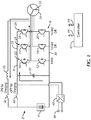
- Fig. 1 illustrates a schematic diagram of a traction system 2 according to an embodiment of the present invention.
- Traction system 2 includes an energy storage device 4.
- energy storage device 4 may be a battery, a flywheel system, a fuel cell, an ultracapacitor, or a combination of ultracapacitors and batteries, as examples.
- Energy storage device 4 is coupled to a voltage converter assembly 6 via a DC bus 8.
- voltage converter assembly 6 is a bi-directional DC/AC voltage inverter.
- Voltage converter assembly 6 includes six half phase modules 10-20 that are paired to form three phase legs 22-26. Each module 14-24 comprises a power switch coupled in antiparallel with a diode.
- insulated gate bipolar transistors IGBTs
- MOSFETs metal oxide semiconductor field effect transistors
- SiC silicon carbide
- GaN gallium nitride
- NJTs bipolar junction transistors
- MCTs metal oxide semiconductor controlled thyristors
- Each phase leg 22-26 is coupled to a pair of conductors 28 and 30.
- a DC link capacitor 32 is coupled to the DC bus 8 to provide a smoothing function and filter high frequency currents for DC bus 8.
- electromechanical device 34 is coupled to voltage converter assembly 6.
- electromechanical device 34 is a traction motor mechanically coupled to one or more driving wheels or axles (not shown) of a vehicle or other electrical apparatus such as a crane, elevator, or lift, as non-limiting examples.
- Electromechanical device 34 includes a plurality of windings 35 coupled to the respective phases 22-26 of the voltage converter assembly 6. While shown in a wye configuration, windings 35 could be configured as a delta configuration or any other appropriate configuration. Any number of windings could be used as well.
- a first charging switch 36 and an optional inductor 38 are directly coupled between the electromechanical device 34 and energy storage device 4.
- the optional inductor 38 is included if sufficient inductance is not provided by the electromechanical device 34.
- a second charging switch 40 is coupled between the energy storage device 4 and the converter assembly 6.
- Charging switches 36 and 40 may be either mechanical contactors or electronic switches, such as IGBTs, MOSFETs, SiC MOSFETs, GaN devices, NJTs, and MCTs as nonlimiting examples. This configuration is capable of both bucking and boosting voltage from an external charging source, which enables utilizing the full capabilities of stationary charging facilities at all charging conditions as long as the energy storage device 4 can be charged at that speed. Further, charging switches 36 and 40 only need to be sized for charging current, significantly reducing size and cost.
- Traction system 2 includes a controller 42 coupled to half phase modules 10-20 and charging switches 36 and 40 via lines 44.
- controller 42 is configured to control the voltage converter assembly 6 to convert a DC voltage or current on DC bus 8 to an AC voltage or current for supply to the windings 35 of electromechanical device 34.
- the DC voltage or current from energy storage device 4 may be converted into an AC voltage or current and delivered to the electromechanical device 34 and then to the driving wheels (not shown).
- the driving wheels may be another type of load including a pump, fan, winch, crane, or other motor driven loads.
- electromechanical device 34 may be operated as a generator to brake driving wheels (not shown) and to supply AC voltage or current to voltage converter assembly 6 for inversion into a DC voltage or current onto DC bus 8 that is suitable for recharging the energy storage device 4.
- traction system 2 When a vehicle or apparatus incorporating traction system 2 is parked or not in use, it may be desirable to plug the vehicle into, for example, a utility grid or to a renewable energy source to refresh or recharge energy storage device 4.
- traction system 2 includes a plug or receptacle 46 configured to mate with an external AC voltage source (not shown).
- AC voltage source (not shown) may be a high-impedance voltage source having any number of phases.
- the plug 46 is coupled to a rectifier 48 to convert AC voltage or current from the AC voltage source (not shown) to DC voltage or current such that DC voltage or current can flow through the DC bus 8.
- phase leg 22 only one of the phase legs 22-26 is used as a DC/DC converter.
- phase leg 22 will be used as the DC/DC converter.
- the controller 42 turns on phase leg 22 and turns off the remaining phase legs 24-26 so that current does not flow to the electromechanical device 34. Electromechanical device 34 remains connected to converter assembly 6.
- first charging switch 36 is closed while second charging switch 40 remains open through use of the controller 42.
- the phase leg 22 in combination with closed second charging switch 36 and inductor 38 forms a bi-directional buck/boost DC/DC converter. While this embodiment uses phase leg 22, any phase leg of a converter tied to the DC bus 8 may be used, including phase legs from additional DC/DC converters, traction inverters, or auxiliary inverters.
- first charging switch 36, and inductor 38 as a DC/DC converter enables rapid charging of the energy storage device 4 without the significant addition of on board charger components, thus reducing costs and space required for the DC bus 8.
- electromechanical device 34 remaining connected to the converter assembly 6 during charging further reduces costs since contactors for the electromechanical device can be expensive. Since only part of the converter assembly 6 is operating, the remainder of the converter assembly 6 is turned off to eliminate unnecessary losses and improve efficiency for low power charging (such as 120 V AC or 240 V AC).
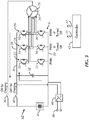
- Fig. 2 is a schematic diagram of a traction system 50 according to another embodiment of the present invention.
- all of the phase legs except one may be used for DC/DC conversion.
- phase legs 24 and 26 along with windings 35 from electromechanical device 34 will be used for DC/DC conversion. If the windings 35 from electromechanical device 34 do not provide sufficient inductance, inductor 38 may be included.
- Inactive phase leg 22 is still connected to the energy storage device 4 through first charging switch 36 and optional inductor 38.
- the controller 42 turns off phase leg 22 and turns on phase legs 26 and 28.
- first charging switch 36 is closed while second charging switch 40 remains open through the controller 42.
- phase legs 24 and 26 This allows output current from phase legs 24 and 26 to be directed to the energy storage device 4 through the first charging switch 36 and optional inductor 38.
- the two active phase legs 24 and 26 in combination with the first charging switch 36 and electromechanical device 34 form a pair of bi-directional buck/boost DC/DC converters. While this embodiment uses phase legs 24 and 26, any phase leg of a converter tied to the DC bus 8 may be used, including phase legs from additional DC/DC converters, traction inverters, or auxiliary inverters.
- first charging switch 36, and electromechanical device 34 as a DC/DC converters enables rapid charging of the energy storage device 4 without the significant addition of on board charger components, thus reducing costs and space required for the DC bus 8. Moreover, the electromechanical device 34 remaining connected to the converter assembly 6 during charging further reduces costs since contactors for the electromechanical device can be expensive. Additionally, the power level is not limiting due to the use of two active phase legs instead of only one. Where the electromechanical device 34 is a permanent magnet or reluctance motor, torque may be produced, which can attract a rotor to a specific position resulting in slight movement. However, a clutch (not shown) may be included between the motor shaft and the transmission to decouple the motor, eliminating the potential shaft movement.
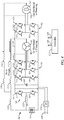
- Fig. 3 is a schematic diagram of a traction system 52 according to yet another embodiment of the present invention.
- all of the phase legs 22-26 along with windings 35 from the electromechanical device 34 are used for DC/DC conversion. If the windings 35 from electromechanical device 34 do not provide sufficient inductance, inductor 38 may be included.
- Electromechanical device 34 is connected to the energy storage device 4 through a first charging switch 36 and optional inductor 38.
- Electromechanical device 34 includes windings 35 in a star or wye connection.
- a neutral or center (not shown) is connected to the energy storage device 4 through first charging switch 36 and optional inductor 38. In this embodiment, all three phase legs 22-26 are used.
- first charging switch 36 When charging, first charging switch 36 is closed while second charging switch 40 remains open through the controller 42. This allows output current from phase legs 22-26 to be directed to the energy storage device 4 through the electromechanical device 34, first charging switch 36, and optional inductor 38.
- the active phase legs 22-26 in combination with the first charging switch 36 and electromechanical device 34 form three bi-directional buck/boost DC/DC converters. While this embodiment uses phase legs 22-26, any phase leg of a converter tied to the DC bus 8 may be used, including phase legs from additional DC/DC converters, traction inverters, or auxiliary inverters.
- phase legs 22-26, first charging switch 36, and electromechanical device 34 as DC/DC converters enables rapid charging of the energy storage device 4 without the significant addition of on board charger components, thus reducing costs and space required for the DC bus 8. Moreover, the electromechanical device 34 remaining connected to the converter assembly 6 during charging further reduces costs since contactors for the electromechanical device can be expensive. Additionally, full power capability is exerted through use of all three phase legs. In this embodiment, the electromechanical device 34 does not produce torque so there is no resulting slight movement. Since the current from the three DC/DC converters do not create a rotating field, there is no torque produced on the shaft during charging. This embodiment may require a connection to a neutral point and the electromechanical device 34 should have windings 35 in a star or wye connection.
- Fig. 4 is a schematic diagram of a traction system 54 with two electromechanical devices and two converter assemblies according to yet another embodiment of the present invention.
- power capability is maximized by configuring all converters tied to a DC bus 56 as buck DC/DC converters.
- Traction system 54 includes an energy storage device 58 coupled to a first voltage converter assembly 60 via the DC bus 56.
- First voltage converter assembly 60 includes two half phase modules 62-64 that are paired to form a single phase leg 66.
- a DC link capacitor 68 is coupled to the DC bus 56 to provide a smoothing function and filter high frequency currents for DC bus 56.
- First voltage converter assembly 60 is coupled to a second voltage converter assembly 70 via the DC bus 56.
- Second voltage converter assembly 70 includes six half phase modules 72-82 that are paired to form three phase legs 84-88.
- a first electromechanical device 90 is coupled to second voltage converter assembly 70 via respective phases 84-88 of the second voltage converter assembly 70.
- the first electromechanical device 90 includes a plurality of windings 91.
- the first electromechanical device 90 is a traction motor.
- Second voltage converter assembly 70 is coupled to a third voltage converter assembly 92 via the DC bus 56.
- Third voltage converter assembly 92 includes four half phase modules 94-100 that are paired to form two phase legs 102-104.
- a second electromechanical device 106 is coupled to third voltage converter assembly 92 via respective phases 102-104.
- the second electromechanical device includes a plurality of windings 107.
- the second electromechanical device 106 may be an alternator or second traction motor as nonlimiting examples.
- Traction system 54 includes a plug or receptacle 108 configured to mate with an AC voltage source (not shown). The plug 108 is coupled to a rectifier 110 to convert AC voltage or current from the AC voltage source (not shown) to DC voltage or current for the DC bus 56.
- a first charging switch 112 is coupled in series with an optional inductor 114 between the first electromechanical device 90 and energy storage device 58.
- a second charging switch 116 is coupled in series with an optional inductor 118 between the second electromechanical device 106 and the energy storage device 58.
- An additional optional inductor 120 can be included between the first and second charging switches 112 and 116 and the energy storage device 58.
- Traction system 54 also includes a controller 124 coupled to half phase modules 62-64, 72-82, and 94-100, and charging switches 112 and 116 via lines 126.
- phase leg 66 in combination with inductor 122 forms a bi-directional buck/boost DC/DC converter.
- phase legs 102-104 in combination with the second charging switch 116 and second electromechanical device 106 form a pair of bi-directional buck/boost DC/DC converters.
- phase legs 84-88 in combination with first charging switch 112 and first electromechanical device 90 form three bi-directional buck/boost DC/DC converters.
- the plurality of bi-directional buck/boost DC/DC converters may all be utilized to maximize power capability while enabling rapid charging of the energy storage device 58 without the significant addition of on board charger components, thus reducing costs and space required for DC bus 56.
- the electromechanical devices 90 and 106 remain connected to the converter assembly during charging, further reducing costs since contactors for the electromechanical devices can be expensive. With this embodiment, the electromechanical devices should not produce torque so there is no resulting slight movement. A neutral is not required in this embodiment as well but may be included if preferred.
- the traction system further comprising an inductor coupled to the DC bus between a phase leg of the voltage converter assembly and the switch.
- the traction system wherein the controller is configured such that a phase leg and the inductor form a DC/DC converter.
- the traction system wherein the controller is configured such that two phase legs and two windings of the electromechanical device form a pair of DC/DC converters.
- the traction system wherein the controller is configured such that all phase legs and all windings of the electromechanical device form a plurality of DC/DC converters.
- the traction system wherein the windings are configured in a wye connection.
- the traction system wherein the electromechanical device is a traction motor.
- the traction system further comprising a receptacle coupled to the DC bus, the receptacle configured to mate with an AC voltage source.
- the traction system wherein the voltage converter assembly is a DC/AC inverter.
- a method for charging a hybrid electric vehicle comprising configuring a controller to:
- phase leg and an inductor form a DC/DC converter.
- the method further comprising configuring the controller to turn on a second phase leg of the voltage converter assembly such that the two phase legs and two windings of the electromechanical deice form a pair of DC/DC converters.
- the method further comprising configuring the controller to turn on all phase legs of the voltage converter assembly such that all phase legs and all windings of the electromechanical device form a plurality of DC/DC converters.
- the voltage converter assembly is a DC/AC inverter.
- the method wherein the formed DC/DC converter is a bi-directional buck/boost converter.
- a traction system comprising:
- the traction system further comprising a receptacle coupled to the DC bus, the receptacle configured to mate with an AC voltage source.
- the traction system wherein the first electromechanical device is a traction motor and the second electromechanical device is an alternator.
Landscapes
- Engineering & Computer Science (AREA)
- Power Engineering (AREA)
- Transportation (AREA)
- Mechanical Engineering (AREA)
- Life Sciences & Earth Sciences (AREA)
- Sustainable Development (AREA)
- Sustainable Energy (AREA)
- Chemical & Material Sciences (AREA)
- Combustion & Propulsion (AREA)
- Electric Propulsion And Braking For Vehicles (AREA)
- Charge And Discharge Circuits For Batteries Or The Like (AREA)
- Dc-Dc Converters (AREA)
Applications Claiming Priority (1)
| Application Number | Priority Date | Filing Date | Title |
|---|---|---|---|
| US15/137,679 US10507716B2 (en) | 2016-04-25 | 2016-04-25 | Integrated charger for vehicles and method of making same |
Publications (2)
| Publication Number | Publication Date |
|---|---|
| EP3238979A1 true EP3238979A1 (fr) | 2017-11-01 |
| EP3238979B1 EP3238979B1 (fr) | 2023-12-06 |
Family
ID=58606172
Family Applications (1)
| Application Number | Title | Priority Date | Filing Date |
|---|---|---|---|
| EP17167717.2A Active EP3238979B1 (fr) | 2016-04-25 | 2017-04-24 | Chargeur intégré pour véhicules et son procédé de fabrication |
Country Status (5)
| Country | Link |
|---|---|
| US (2) | US10507716B2 (fr) |
| EP (1) | EP3238979B1 (fr) |
| JP (1) | JP6924061B2 (fr) |
| KR (1) | KR102370937B1 (fr) |
| CN (1) | CN107364350A (fr) |
Cited By (6)
| Publication number | Priority date | Publication date | Assignee | Title |
|---|---|---|---|---|
| GB2561588A (en) * | 2017-04-19 | 2018-10-24 | Sevcon Ltd | DC-DC converter |
| WO2020178181A1 (fr) * | 2019-03-01 | 2020-09-10 | Nidec Ssb Wind Systems Gmbh | Entraînement électrique |
| CN112937332A (zh) * | 2021-01-21 | 2021-06-11 | 华为技术有限公司 | 一种充电系统及电动汽车 |
| CN112937337A (zh) * | 2021-01-21 | 2021-06-11 | 华为技术有限公司 | 一种充电系统及电动汽车 |
| EP4039529A1 (fr) * | 2021-02-09 | 2022-08-10 | Huawei Digital Power Technologies Co., Ltd. | Système d'entraînement de moteur excité électriquement intégré avec chargeur embarqué, et véhicule électrique |
| EP4303068A3 (fr) * | 2022-06-16 | 2024-03-06 | Chongqing Changan New Energy Vehicles Technology Co., Ltd | Dispositif adaptateur compatible de charge cc haute tension multi-moteur, système et procédé de commande, et automobile |
Families Citing this family (28)
| Publication number | Priority date | Publication date | Assignee | Title |
|---|---|---|---|---|
| US11479139B2 (en) | 2015-09-11 | 2022-10-25 | Invertedpower Pty Ltd | Methods and systems for an integrated charging system for an electric vehicle |
| US10333337B2 (en) * | 2015-11-30 | 2019-06-25 | Volta Power Systems, L.L.C. | Secondary power system |
| CA3078598A1 (fr) * | 2017-10-06 | 2019-04-11 | Proterra Inc. | Charge en depot d'une flotte de vehicules electriques |
| US11801763B2 (en) * | 2017-12-19 | 2023-10-31 | Ford Global Technologies, Llc | Integrated DC vehicle charger |
| US10369900B1 (en) * | 2018-02-20 | 2019-08-06 | GM Global Technology Operations LLC | Onboard DC charging circuit using traction drive components |
| US11518262B2 (en) * | 2018-08-03 | 2022-12-06 | University Of Ontario Institute Of Technology | Wide-output voltage range on-board battery charger for electric vehicles |
| DE102018218824B3 (de) * | 2018-11-05 | 2020-02-27 | Volkswagen Aktiengesellschaft | Stromrichteranordnung für ein Fahrzeug und Fahrzeug mit einer solchen Stromrichteranordnung |
| CN111355429B (zh) * | 2018-12-21 | 2021-09-03 | 比亚迪股份有限公司 | 电机驱动装置、控制方法、车辆及可读存储介质 |
| CN111347925B (zh) * | 2018-12-21 | 2022-03-18 | 比亚迪股份有限公司 | 一种车辆、电机控制电路、动力电池充电方法与加热方法 |
| CN110356268B (zh) * | 2019-06-25 | 2021-08-03 | 华为技术有限公司 | 一种车载充放电装置和系统 |
| KR102796848B1 (ko) * | 2019-08-06 | 2025-04-17 | 현대자동차주식회사 | 모터 구동 시스템을 이용한 충전 시스템 및 방법 |
| US12017544B2 (en) | 2019-11-22 | 2024-06-25 | Cummins Inc. | Fault tolerant inverter for partial phase loss in multi-phase machines |
| EP3988377B1 (fr) * | 2020-10-23 | 2024-01-03 | Ningbo Geely Automobile Research & Development Co. Ltd. | Système électrique de véhicule |
| CN116325410A (zh) | 2020-12-11 | 2023-06-23 | 康明斯公司 | 用于隔离式dc/dc转换器的方法和设备 |
| US12101047B2 (en) * | 2022-04-11 | 2024-09-24 | Borg Warner Luxembourg Automotive Systems SA | Systems and methods for inverter with hybrid power device switching |
| KR20240040231A (ko) | 2022-09-21 | 2024-03-28 | 현대자동차주식회사 | 직류 컨버터를 포함하는 차량 및 이의 제어 방법 |
| DE112023004484T5 (de) | 2022-10-27 | 2025-09-11 | Vitesco Technologies USA, LLC | Fahrzeug-Hochspannungselektronikbox |
| US12636964B2 (en) * | 2022-11-07 | 2026-05-26 | Karma Automotive Inc. | Integrated bidirectional charger and inverter for electric vehicles |
| US12447835B2 (en) | 2022-11-10 | 2025-10-21 | Patrick Industries, Inc. | Vehicle charging arrangement |
| CN116208062B (zh) * | 2023-03-06 | 2025-09-26 | 深蓝汽车科技有限公司 | 电机控制系统、电机控制系统的控制方法及车辆 |
| EP4709609A1 (fr) | 2023-05-09 | 2026-03-18 | Schaeffler Technologies AG & Co. KG | Boîtier électronique à haute tension de véhicule |
| US12658710B1 (en) | 2023-07-27 | 2026-06-16 | One Three Energy, Inc. | Base station power converter suitable for single-phase power sources |
| US20250050760A1 (en) * | 2023-08-11 | 2025-02-13 | Ford Global Technologies, Llc | Automotive integrated on-board charger using inverter and motor windings |
| US20250105760A1 (en) * | 2023-09-21 | 2025-03-27 | Allegro Microsystems, Llc | Active dc bus discharge |
| US20250239944A1 (en) * | 2024-01-22 | 2025-07-24 | Ford Global Technologies, Llc | Power module gate oxide self-healing method |
| US20250303893A1 (en) * | 2024-03-29 | 2025-10-02 | Ford Global Technologies, Llc | Integrated ac on-board charger |
| CN121055718A (zh) * | 2024-05-31 | 2025-12-02 | 罗伯特·博世有限公司 | 逆变器的复用电路、方法和控制器 |
| US12676567B2 (en) | 2024-08-27 | 2026-07-07 | Ford Global Technologies, Llc | Externally excited synchronous machine-based electric drive integrating galvanically isolated AC |
Citations (6)
| Publication number | Priority date | Publication date | Assignee | Title |
|---|---|---|---|---|
| US20100096926A1 (en) * | 2008-10-22 | 2010-04-22 | Robert Dean King | Apparatus for transferring energy using power electronics and machine inductance and method of manufacturing same |
| EP2179882A2 (fr) * | 2008-10-22 | 2010-04-28 | General Electric Company | Appareil pour transfert d'énergie utilisant un convertisseur et son procédé de fabrication |
| EP2290778A2 (fr) * | 2009-08-31 | 2011-03-02 | General Electric Company | Appareil de transfert d'énergie au moyen d'appareils électroniques embarqués et son procédé de fabrication |
| EP2450222A2 (fr) * | 2010-11-05 | 2012-05-09 | General Electric Company | Appareil de transfert d'énergie au moyen d'appareils électroniques embarqués avec isolation de transformateur haute fréquence et son procédé de fabrication |
| US20130234675A1 (en) * | 2012-03-08 | 2013-09-12 | Robert Dean King | Apparatus for transferring energy using onboard power electronics and method of manufacturing same |
| EP2875984A2 (fr) * | 2013-11-20 | 2015-05-27 | General Electric Company | Appareil de charge rapide au moyen d'appareils électroniques embarqués et son procédé de fabrication |
Family Cites Families (24)
| Publication number | Priority date | Publication date | Assignee | Title |
|---|---|---|---|---|
| US4920475A (en) | 1988-03-07 | 1990-04-24 | California Institute Of Technology | Integrated traction inverter and battery charger apparatus |
| JP3284571B2 (ja) | 1992-01-24 | 2002-05-20 | 株式会社明電舎 | 電気自動車 |
| US5341075A (en) * | 1993-03-10 | 1994-08-23 | A.C. Propulsion, Inc. | Combined motor drive and battery recharge system |
| JP3477850B2 (ja) | 1994-10-26 | 2003-12-10 | 株式会社明電舎 | 電気自動車用充電器 |
| FR2738411B1 (fr) * | 1995-08-30 | 1997-10-17 | Renault | Systeme d'alimentation electrique mixte onduleur et convertisseur alternatif-continu |
| US6724100B1 (en) | 2000-09-08 | 2004-04-20 | Ford Motor Company | HEV charger/generator unit |
| JP4120310B2 (ja) * | 2002-08-06 | 2008-07-16 | トヨタ自動車株式会社 | 電気負荷駆動装置、電気負荷駆動方法、電気負荷の駆動をコンピュータに実行させるプログラムを記録したコンピュータ読取り可能な記録媒体 |
| JP2005033954A (ja) * | 2003-07-09 | 2005-02-03 | Toyota Motor Corp | バッテリ充電装置 |
| US7589986B2 (en) * | 2006-04-19 | 2009-09-15 | International Rectifier Corporation | Single stage integrated boost inverter motor drive circuit |
| KR100906908B1 (ko) | 2006-12-11 | 2009-07-08 | 현대자동차주식회사 | 하이브리드 전기 차량의 배터리 충전량 제어 방법 |
| US20080205109A1 (en) | 2007-02-26 | 2008-08-28 | Lear Corporation | Energy distribution system for vehicle |
| JP5644070B2 (ja) * | 2008-07-16 | 2014-12-24 | 株式会社豊田中央研究所 | 電力制御装置 |
| FR2939244B1 (fr) * | 2008-12-03 | 2012-08-17 | Renault Sas | Boitier d'interconnexion pour vehicule automobile |
| JP5321282B2 (ja) * | 2009-06-25 | 2013-10-23 | 株式会社豊田中央研究所 | 電力制御装置 |
| US8421271B2 (en) | 2009-08-31 | 2013-04-16 | General Electric Company | Apparatus for transferring energy using onboard power electronics and method of manufacturing same |
| KR101171908B1 (ko) * | 2010-07-09 | 2012-08-07 | 현대자동차주식회사 | 플러그인 하이브리드 자동차의 충전장치 |
| KR101189237B1 (ko) * | 2010-07-09 | 2012-10-09 | 현대자동차주식회사 | 하이브리드 자동차의 충전장치 및 방법 |
| KR101220367B1 (ko) | 2010-08-31 | 2013-01-09 | 현대자동차주식회사 | 플러그인 하이브리드 자동차의 충전장치 및 방법 |
| US20120153884A1 (en) * | 2010-12-21 | 2012-06-21 | Caterpillar Inc. | Integrated motor controller system |
| DE102011081725A1 (de) * | 2011-08-29 | 2013-02-28 | Robert Bosch Gmbh | Verfahren und Vorrichtung zum Laden einer Batterie eines elektrischen Antriebs unter Verwendung von Komponenten des elektrischen Antriebs |
| FR2987946B1 (fr) * | 2012-03-09 | 2014-03-07 | Valeo Sys Controle Moteur Sas | Procede de decharge d'au moins un condensateur d'un circuit electrique |
| JP6439282B2 (ja) * | 2014-06-09 | 2018-12-19 | 日産自動車株式会社 | 充電システム、給電車両、充電車両、及び充電方法 |
| GB2531036A (en) * | 2014-10-08 | 2016-04-13 | Nissan Motor Mfg (Uk) Ltd | Electric drive and charger system for a grid enabled vehicle |
| DE102014225506A1 (de) * | 2014-12-11 | 2016-06-16 | Robert Bosch Gmbh | Vorrichtung zum Laden einer Batterieeinheit und Betreiben einer Lasteinheit über einen Wechselrichter |
-
2016
- 2016-04-25 US US15/137,679 patent/US10507716B2/en active Active
-
2017
- 2017-04-11 JP JP2017077895A patent/JP6924061B2/ja not_active Expired - Fee Related
- 2017-04-18 KR KR1020170049653A patent/KR102370937B1/ko not_active Expired - Fee Related
- 2017-04-24 EP EP17167717.2A patent/EP3238979B1/fr active Active
- 2017-04-25 CN CN201710280077.2A patent/CN107364350A/zh active Pending
-
2019
- 2019-11-06 US US16/675,703 patent/US20200070643A1/en not_active Abandoned
Patent Citations (7)
| Publication number | Priority date | Publication date | Assignee | Title |
|---|---|---|---|---|
| US20100096926A1 (en) * | 2008-10-22 | 2010-04-22 | Robert Dean King | Apparatus for transferring energy using power electronics and machine inductance and method of manufacturing same |
| EP2179882A2 (fr) * | 2008-10-22 | 2010-04-28 | General Electric Company | Appareil pour transfert d'énergie utilisant un convertisseur et son procédé de fabrication |
| EP2290778A2 (fr) * | 2009-08-31 | 2011-03-02 | General Electric Company | Appareil de transfert d'énergie au moyen d'appareils électroniques embarqués et son procédé de fabrication |
| US8030884B2 (en) | 2009-08-31 | 2011-10-04 | General Electric Company | Apparatus for transferring energy using onboard power electronics and method of manufacturing same |
| EP2450222A2 (fr) * | 2010-11-05 | 2012-05-09 | General Electric Company | Appareil de transfert d'énergie au moyen d'appareils électroniques embarqués avec isolation de transformateur haute fréquence et son procédé de fabrication |
| US20130234675A1 (en) * | 2012-03-08 | 2013-09-12 | Robert Dean King | Apparatus for transferring energy using onboard power electronics and method of manufacturing same |
| EP2875984A2 (fr) * | 2013-11-20 | 2015-05-27 | General Electric Company | Appareil de charge rapide au moyen d'appareils électroniques embarqués et son procédé de fabrication |
Cited By (12)
| Publication number | Priority date | Publication date | Assignee | Title |
|---|---|---|---|---|
| GB2561588A (en) * | 2017-04-19 | 2018-10-24 | Sevcon Ltd | DC-DC converter |
| GB2561588B (en) * | 2017-04-19 | 2020-01-08 | Sevcon Ltd | DC-DC converter |
| US11121631B2 (en) | 2017-04-19 | 2021-09-14 | Sevcon Limited | DC-DC converter |
| WO2020178181A1 (fr) * | 2019-03-01 | 2020-09-10 | Nidec Ssb Wind Systems Gmbh | Entraînement électrique |
| CN112937332A (zh) * | 2021-01-21 | 2021-06-11 | 华为技术有限公司 | 一种充电系统及电动汽车 |
| CN112937337A (zh) * | 2021-01-21 | 2021-06-11 | 华为技术有限公司 | 一种充电系统及电动汽车 |
| US20220209565A1 (en) * | 2021-01-21 | 2022-06-30 | Huawei Digital Power Technologies Co., Ltd. | Charging system and electric vehicle |
| EP4032743A1 (fr) * | 2021-01-21 | 2022-07-27 | Huawei Digital Power Technologies Co., Ltd. | Système de charge et véhicule électrique |
| US11791649B2 (en) | 2021-01-21 | 2023-10-17 | Huawei Digital Power Technologies Co., Ltd. | Charging system and electric vehicle |
| EP4039529A1 (fr) * | 2021-02-09 | 2022-08-10 | Huawei Digital Power Technologies Co., Ltd. | Système d'entraînement de moteur excité électriquement intégré avec chargeur embarqué, et véhicule électrique |
| US12172532B2 (en) | 2021-02-09 | 2024-12-24 | Huawei Digital Power Technologies Co., Ltd. | Electrically excited motor drive system integrated with OBC, and electric vehicle |
| EP4303068A3 (fr) * | 2022-06-16 | 2024-03-06 | Chongqing Changan New Energy Vehicles Technology Co., Ltd | Dispositif adaptateur compatible de charge cc haute tension multi-moteur, système et procédé de commande, et automobile |
Also Published As
| Publication number | Publication date |
|---|---|
| EP3238979B1 (fr) | 2023-12-06 |
| US20200070643A1 (en) | 2020-03-05 |
| CN107364350A (zh) | 2017-11-21 |
| US10507716B2 (en) | 2019-12-17 |
| US20170305283A1 (en) | 2017-10-26 |
| KR102370937B1 (ko) | 2022-03-07 |
| JP2017200428A (ja) | 2017-11-02 |
| JP6924061B2 (ja) | 2021-08-25 |
| KR20170121697A (ko) | 2017-11-02 |
Similar Documents
| Publication | Publication Date | Title |
|---|---|---|
| EP3238979B1 (fr) | Chargeur intégré pour véhicules et son procédé de fabrication | |
| US11167654B2 (en) | Apparatus for transferring energy using power electronics and machine inductance and method of manufacturing same | |
| CN102457089B (zh) | 使用具有高频变压器隔离的车载功率电子设备转移能量的设备及其制造方法 | |
| US8421271B2 (en) | Apparatus for transferring energy using onboard power electronics and method of manufacturing same | |
| US8030884B2 (en) | Apparatus for transferring energy using onboard power electronics and method of manufacturing same | |
| US9238415B2 (en) | Apparatus for rapid charging using onboard power electronics and method of manufacturing same |
Legal Events
| Date | Code | Title | Description |
|---|---|---|---|
| PUAI | Public reference made under article 153(3) epc to a published international application that has entered the european phase |
Free format text: ORIGINAL CODE: 0009012 |
|
| STAA | Information on the status of an ep patent application or granted ep patent |
Free format text: STATUS: THE APPLICATION HAS BEEN PUBLISHED |
|
| AK | Designated contracting states |
Kind code of ref document: A1 Designated state(s): AL AT BE BG CH CY CZ DE DK EE ES FI FR GB GR HR HU IE IS IT LI LT LU LV MC MK MT NL NO PL PT RO RS SE SI SK SM TR |
|
| AX | Request for extension of the european patent |
Extension state: BA ME |
|
| STAA | Information on the status of an ep patent application or granted ep patent |
Free format text: STATUS: REQUEST FOR EXAMINATION WAS MADE |
|
| 17P | Request for examination filed |
Effective date: 20180502 |
|
| RBV | Designated contracting states (corrected) |
Designated state(s): AL AT BE BG CH CY CZ DE DK EE ES FI FR GB GR HR HU IE IS IT LI LT LU LV MC MK MT NL NO PL PT RO RS SE SI SK SM TR |
|
| STAA | Information on the status of an ep patent application or granted ep patent |
Free format text: STATUS: EXAMINATION IS IN PROGRESS |
|
| 17Q | First examination report despatched |
Effective date: 20200924 |
|
| REG | Reference to a national code |
Ref country code: DE Ref legal event code: R079 Free format text: PREVIOUS MAIN CLASS: B60L0011180000 Ipc: B60L0053240000 Ref country code: DE Ref legal event code: R079 Ref document number: 602017077164 Country of ref document: DE Free format text: PREVIOUS MAIN CLASS: B60L0011180000 Ipc: B60L0053240000 |
|
| GRAP | Despatch of communication of intention to grant a patent |
Free format text: ORIGINAL CODE: EPIDOSNIGR1 |
|
| STAA | Information on the status of an ep patent application or granted ep patent |
Free format text: STATUS: GRANT OF PATENT IS INTENDED |
|
| RIC1 | Information provided on ipc code assigned before grant |
Ipc: B60L 50/60 20190101ALI20230612BHEP Ipc: B60L 50/51 20190101ALI20230612BHEP Ipc: B60L 53/24 20190101AFI20230612BHEP |
|
| INTG | Intention to grant announced |
Effective date: 20230704 |
|
| GRAS | Grant fee paid |
Free format text: ORIGINAL CODE: EPIDOSNIGR3 |
|
| GRAA | (expected) grant |
Free format text: ORIGINAL CODE: 0009210 |
|
| STAA | Information on the status of an ep patent application or granted ep patent |
Free format text: STATUS: THE PATENT HAS BEEN GRANTED |
|
| AK | Designated contracting states |
Kind code of ref document: B1 Designated state(s): AL AT BE BG CH CY CZ DE DK EE ES FI FR GB GR HR HU IE IS IT LI LT LU LV MC MK MT NL NO PL PT RO RS SE SI SK SM TR |
|
| REG | Reference to a national code |
Ref country code: GB Ref legal event code: FG4D |
|
| REG | Reference to a national code |
Ref country code: DE Ref legal event code: R096 Ref document number: 602017077164 Country of ref document: DE |
|
| REG | Reference to a national code |
Ref country code: CH Ref legal event code: EP |
|
| REG | Reference to a national code |
Ref country code: IE Ref legal event code: FG4D |
|
| REG | Reference to a national code |
Ref country code: NL Ref legal event code: FP |
|
| REG | Reference to a national code |
Ref country code: LT Ref legal event code: MG9D |
|
| PG25 | Lapsed in a contracting state [announced via postgrant information from national office to epo] |
Ref country code: GR Free format text: LAPSE BECAUSE OF FAILURE TO SUBMIT A TRANSLATION OF THE DESCRIPTION OR TO PAY THE FEE WITHIN THE PRESCRIBED TIME-LIMIT Effective date: 20240307 |
|
| PG25 | Lapsed in a contracting state [announced via postgrant information from national office to epo] |
Ref country code: LT Free format text: LAPSE BECAUSE OF FAILURE TO SUBMIT A TRANSLATION OF THE DESCRIPTION OR TO PAY THE FEE WITHIN THE PRESCRIBED TIME-LIMIT Effective date: 20231206 |
|
| PG25 | Lapsed in a contracting state [announced via postgrant information from national office to epo] |
Ref country code: ES Free format text: LAPSE BECAUSE OF FAILURE TO SUBMIT A TRANSLATION OF THE DESCRIPTION OR TO PAY THE FEE WITHIN THE PRESCRIBED TIME-LIMIT Effective date: 20231206 |
|
| PG25 | Lapsed in a contracting state [announced via postgrant information from national office to epo] |
Ref country code: LT Free format text: LAPSE BECAUSE OF FAILURE TO SUBMIT A TRANSLATION OF THE DESCRIPTION OR TO PAY THE FEE WITHIN THE PRESCRIBED TIME-LIMIT Effective date: 20231206 Ref country code: GR Free format text: LAPSE BECAUSE OF FAILURE TO SUBMIT A TRANSLATION OF THE DESCRIPTION OR TO PAY THE FEE WITHIN THE PRESCRIBED TIME-LIMIT Effective date: 20240307 Ref country code: ES Free format text: LAPSE BECAUSE OF FAILURE TO SUBMIT A TRANSLATION OF THE DESCRIPTION OR TO PAY THE FEE WITHIN THE PRESCRIBED TIME-LIMIT Effective date: 20231206 Ref country code: BG Free format text: LAPSE BECAUSE OF FAILURE TO SUBMIT A TRANSLATION OF THE DESCRIPTION OR TO PAY THE FEE WITHIN THE PRESCRIBED TIME-LIMIT Effective date: 20240306 |
|
| REG | Reference to a national code |
Ref country code: AT Ref legal event code: MK05 Ref document number: 1638073 Country of ref document: AT Kind code of ref document: T Effective date: 20231206 |
|
| PG25 | Lapsed in a contracting state [announced via postgrant information from national office to epo] |
Ref country code: SE Free format text: LAPSE BECAUSE OF FAILURE TO SUBMIT A TRANSLATION OF THE DESCRIPTION OR TO PAY THE FEE WITHIN THE PRESCRIBED TIME-LIMIT Effective date: 20231206 Ref country code: RS Free format text: LAPSE BECAUSE OF FAILURE TO SUBMIT A TRANSLATION OF THE DESCRIPTION OR TO PAY THE FEE WITHIN THE PRESCRIBED TIME-LIMIT Effective date: 20231206 Ref country code: NO Free format text: LAPSE BECAUSE OF FAILURE TO SUBMIT A TRANSLATION OF THE DESCRIPTION OR TO PAY THE FEE WITHIN THE PRESCRIBED TIME-LIMIT Effective date: 20240306 Ref country code: LV Free format text: LAPSE BECAUSE OF FAILURE TO SUBMIT A TRANSLATION OF THE DESCRIPTION OR TO PAY THE FEE WITHIN THE PRESCRIBED TIME-LIMIT Effective date: 20231206 Ref country code: HR Free format text: LAPSE BECAUSE OF FAILURE TO SUBMIT A TRANSLATION OF THE DESCRIPTION OR TO PAY THE FEE WITHIN THE PRESCRIBED TIME-LIMIT Effective date: 20231206 |
|
| PG25 | Lapsed in a contracting state [announced via postgrant information from national office to epo] |
Ref country code: IS Free format text: LAPSE BECAUSE OF FAILURE TO SUBMIT A TRANSLATION OF THE DESCRIPTION OR TO PAY THE FEE WITHIN THE PRESCRIBED TIME-LIMIT Effective date: 20240406 |
|
| PG25 | Lapsed in a contracting state [announced via postgrant information from national office to epo] |
Ref country code: CZ Free format text: LAPSE BECAUSE OF FAILURE TO SUBMIT A TRANSLATION OF THE DESCRIPTION OR TO PAY THE FEE WITHIN THE PRESCRIBED TIME-LIMIT Effective date: 20231206 Ref country code: AT Free format text: LAPSE BECAUSE OF FAILURE TO SUBMIT A TRANSLATION OF THE DESCRIPTION OR TO PAY THE FEE WITHIN THE PRESCRIBED TIME-LIMIT Effective date: 20231206 |
|
| PG25 | Lapsed in a contracting state [announced via postgrant information from national office to epo] |
Ref country code: SK Free format text: LAPSE BECAUSE OF FAILURE TO SUBMIT A TRANSLATION OF THE DESCRIPTION OR TO PAY THE FEE WITHIN THE PRESCRIBED TIME-LIMIT Effective date: 20231206 |
|
| PG25 | Lapsed in a contracting state [announced via postgrant information from national office to epo] |
Ref country code: SM Free format text: LAPSE BECAUSE OF FAILURE TO SUBMIT A TRANSLATION OF THE DESCRIPTION OR TO PAY THE FEE WITHIN THE PRESCRIBED TIME-LIMIT Effective date: 20231206 Ref country code: SK Free format text: LAPSE BECAUSE OF FAILURE TO SUBMIT A TRANSLATION OF THE DESCRIPTION OR TO PAY THE FEE WITHIN THE PRESCRIBED TIME-LIMIT Effective date: 20231206 Ref country code: RO Free format text: LAPSE BECAUSE OF FAILURE TO SUBMIT A TRANSLATION OF THE DESCRIPTION OR TO PAY THE FEE WITHIN THE PRESCRIBED TIME-LIMIT Effective date: 20231206 Ref country code: IS Free format text: LAPSE BECAUSE OF FAILURE TO SUBMIT A TRANSLATION OF THE DESCRIPTION OR TO PAY THE FEE WITHIN THE PRESCRIBED TIME-LIMIT Effective date: 20240406 Ref country code: EE Free format text: LAPSE BECAUSE OF FAILURE TO SUBMIT A TRANSLATION OF THE DESCRIPTION OR TO PAY THE FEE WITHIN THE PRESCRIBED TIME-LIMIT Effective date: 20231206 Ref country code: CZ Free format text: LAPSE BECAUSE OF FAILURE TO SUBMIT A TRANSLATION OF THE DESCRIPTION OR TO PAY THE FEE WITHIN THE PRESCRIBED TIME-LIMIT Effective date: 20231206 Ref country code: AT Free format text: LAPSE BECAUSE OF FAILURE TO SUBMIT A TRANSLATION OF THE DESCRIPTION OR TO PAY THE FEE WITHIN THE PRESCRIBED TIME-LIMIT Effective date: 20231206 |
|
| PG25 | Lapsed in a contracting state [announced via postgrant information from national office to epo] |
Ref country code: PT Free format text: LAPSE BECAUSE OF FAILURE TO SUBMIT A TRANSLATION OF THE DESCRIPTION OR TO PAY THE FEE WITHIN THE PRESCRIBED TIME-LIMIT Effective date: 20240408 Ref country code: PL Free format text: LAPSE BECAUSE OF FAILURE TO SUBMIT A TRANSLATION OF THE DESCRIPTION OR TO PAY THE FEE WITHIN THE PRESCRIBED TIME-LIMIT Effective date: 20231206 |
|
| REG | Reference to a national code |
Ref country code: DE Ref legal event code: R097 Ref document number: 602017077164 Country of ref document: DE |
|
| PG25 | Lapsed in a contracting state [announced via postgrant information from national office to epo] |
Ref country code: DK Free format text: LAPSE BECAUSE OF FAILURE TO SUBMIT A TRANSLATION OF THE DESCRIPTION OR TO PAY THE FEE WITHIN THE PRESCRIBED TIME-LIMIT Effective date: 20231206 |
|
| PLBE | No opposition filed within time limit |
Free format text: ORIGINAL CODE: 0009261 |
|
| STAA | Information on the status of an ep patent application or granted ep patent |
Free format text: STATUS: NO OPPOSITION FILED WITHIN TIME LIMIT |
|
| PG25 | Lapsed in a contracting state [announced via postgrant information from national office to epo] |
Ref country code: SI Free format text: LAPSE BECAUSE OF FAILURE TO SUBMIT A TRANSLATION OF THE DESCRIPTION OR TO PAY THE FEE WITHIN THE PRESCRIBED TIME-LIMIT Effective date: 20231206 |
|
| PG25 | Lapsed in a contracting state [announced via postgrant information from national office to epo] |
Ref country code: SI Free format text: LAPSE BECAUSE OF FAILURE TO SUBMIT A TRANSLATION OF THE DESCRIPTION OR TO PAY THE FEE WITHIN THE PRESCRIBED TIME-LIMIT Effective date: 20231206 Ref country code: DK Free format text: LAPSE BECAUSE OF FAILURE TO SUBMIT A TRANSLATION OF THE DESCRIPTION OR TO PAY THE FEE WITHIN THE PRESCRIBED TIME-LIMIT Effective date: 20231206 |
|
| 26N | No opposition filed |
Effective date: 20240909 |
|
| PG25 | Lapsed in a contracting state [announced via postgrant information from national office to epo] |
Ref country code: MC Free format text: LAPSE BECAUSE OF FAILURE TO SUBMIT A TRANSLATION OF THE DESCRIPTION OR TO PAY THE FEE WITHIN THE PRESCRIBED TIME-LIMIT Effective date: 20231206 |
|
| PG25 | Lapsed in a contracting state [announced via postgrant information from national office to epo] |
Ref country code: MC Free format text: LAPSE BECAUSE OF FAILURE TO SUBMIT A TRANSLATION OF THE DESCRIPTION OR TO PAY THE FEE WITHIN THE PRESCRIBED TIME-LIMIT Effective date: 20231206 |
|
| REG | Reference to a national code |
Ref country code: CH Ref legal event code: PL |
|
| PG25 | Lapsed in a contracting state [announced via postgrant information from national office to epo] |
Ref country code: LU Free format text: LAPSE BECAUSE OF NON-PAYMENT OF DUE FEES Effective date: 20240424 |
|
| REG | Reference to a national code |
Ref country code: BE Ref legal event code: MM Effective date: 20240430 |
|
| PG25 | Lapsed in a contracting state [announced via postgrant information from national office to epo] |
Ref country code: LU Free format text: LAPSE BECAUSE OF NON-PAYMENT OF DUE FEES Effective date: 20240424 |
|
| PG25 | Lapsed in a contracting state [announced via postgrant information from national office to epo] |
Ref country code: BE Free format text: LAPSE BECAUSE OF NON-PAYMENT OF DUE FEES Effective date: 20240430 |
|
| PG25 | Lapsed in a contracting state [announced via postgrant information from national office to epo] |
Ref country code: BE Free format text: LAPSE BECAUSE OF NON-PAYMENT OF DUE FEES Effective date: 20240430 Ref country code: CH Free format text: LAPSE BECAUSE OF NON-PAYMENT OF DUE FEES Effective date: 20240430 |
|
| PG25 | Lapsed in a contracting state [announced via postgrant information from national office to epo] |
Ref country code: IE Free format text: LAPSE BECAUSE OF NON-PAYMENT OF DUE FEES Effective date: 20240424 |
|
| PGFP | Annual fee paid to national office [announced via postgrant information from national office to epo] |
Ref country code: NL Payment date: 20250427 Year of fee payment: 9 |
|
| PGFP | Annual fee paid to national office [announced via postgrant information from national office to epo] |
Ref country code: DE Payment date: 20250429 Year of fee payment: 9 |
|
| PGFP | Annual fee paid to national office [announced via postgrant information from national office to epo] |
Ref country code: GB Payment date: 20250428 Year of fee payment: 9 |
|
| PGFP | Annual fee paid to national office [announced via postgrant information from national office to epo] |
Ref country code: IT Payment date: 20250422 Year of fee payment: 9 |
|
| PGFP | Annual fee paid to national office [announced via postgrant information from national office to epo] |
Ref country code: FR Payment date: 20250425 Year of fee payment: 9 |
|
| PG25 | Lapsed in a contracting state [announced via postgrant information from national office to epo] |
Ref country code: CY Free format text: LAPSE BECAUSE OF FAILURE TO SUBMIT A TRANSLATION OF THE DESCRIPTION OR TO PAY THE FEE WITHIN THE PRESCRIBED TIME-LIMIT; INVALID AB INITIO Effective date: 20170424 |
|
| PG25 | Lapsed in a contracting state [announced via postgrant information from national office to epo] |
Ref country code: HU Free format text: LAPSE BECAUSE OF FAILURE TO SUBMIT A TRANSLATION OF THE DESCRIPTION OR TO PAY THE FEE WITHIN THE PRESCRIBED TIME-LIMIT; INVALID AB INITIO Effective date: 20170424 |
|
| PG25 | Lapsed in a contracting state [announced via postgrant information from national office to epo] |
Ref country code: FI Free format text: LAPSE BECAUSE OF FAILURE TO SUBMIT A TRANSLATION OF THE DESCRIPTION OR TO PAY THE FEE WITHIN THE PRESCRIBED TIME-LIMIT Effective date: 20231207 |
|
| PG25 | Lapsed in a contracting state [announced via postgrant information from national office to epo] |
Ref country code: TR Free format text: LAPSE BECAUSE OF FAILURE TO SUBMIT A TRANSLATION OF THE DESCRIPTION OR TO PAY THE FEE WITHIN THE PRESCRIBED TIME-LIMIT Effective date: 20231206 |