EP3239065A1 - Palette zum transfer einer glasplatte - Google Patents
Palette zum transfer einer glasplatte Download PDFInfo
- Publication number
- EP3239065A1 EP3239065A1 EP15873576.1A EP15873576A EP3239065A1 EP 3239065 A1 EP3239065 A1 EP 3239065A1 EP 15873576 A EP15873576 A EP 15873576A EP 3239065 A1 EP3239065 A1 EP 3239065A1
- Authority
- EP
- European Patent Office
- Prior art keywords
- plate
- glass plate
- pallet
- washer
- glass
- Prior art date
- Legal status (The legal status is an assumption and is not a legal conclusion. Google has not performed a legal analysis and makes no representation as to the accuracy of the status listed.)
- Granted
Links
Images


Classifications
-
- B—PERFORMING OPERATIONS; TRANSPORTING
- B65—CONVEYING; PACKING; STORING; HANDLING THIN OR FILAMENTARY MATERIAL
- B65D—CONTAINERS FOR STORAGE OR TRANSPORT OF ARTICLES OR MATERIALS, e.g. BAGS, BARRELS, BOTTLES, BOXES, CANS, CARTONS, CRATES, DRUMS, JARS, TANKS, HOPPERS, FORWARDING CONTAINERS; ACCESSORIES, CLOSURES, OR FITTINGS THEREFOR; PACKAGING ELEMENTS; PACKAGES
- B65D85/00—Containers, packaging elements or packages, specially adapted for particular articles or materials
- B65D85/30—Containers, packaging elements or packages, specially adapted for particular articles or materials for articles particularly sensitive to damage by shock or pressure
- B65D85/48—Containers, packaging elements or packages, specially adapted for particular articles or materials for articles particularly sensitive to damage by shock or pressure for glass sheets
-
- B—PERFORMING OPERATIONS; TRANSPORTING
- B65—CONVEYING; PACKING; STORING; HANDLING THIN OR FILAMENTARY MATERIAL
- B65D—CONTAINERS FOR STORAGE OR TRANSPORT OF ARTICLES OR MATERIALS, e.g. BAGS, BARRELS, BOTTLES, BOXES, CANS, CARTONS, CRATES, DRUMS, JARS, TANKS, HOPPERS, FORWARDING CONTAINERS; ACCESSORIES, CLOSURES, OR FITTINGS THEREFOR; PACKAGING ELEMENTS; PACKAGES
- B65D19/00—Pallets or like platforms, with or without side walls, for supporting loads to be lifted or lowered
- B65D19/38—Details or accessories
- B65D19/44—Elements or devices for locating articles on platforms
-
- B—PERFORMING OPERATIONS; TRANSPORTING
- B65—CONVEYING; PACKING; STORING; HANDLING THIN OR FILAMENTARY MATERIAL
- B65G—TRANSPORT OR STORAGE DEVICES, e.g. CONVEYORS FOR LOADING OR TIPPING, SHOP CONVEYOR SYSTEMS OR PNEUMATIC TUBE CONVEYORS
- B65G49/00—Conveying systems characterised by their application for specified purposes not otherwise provided for
- B65G49/05—Conveying systems characterised by their application for specified purposes not otherwise provided for for fragile or damageable materials or articles
- B65G49/06—Conveying systems characterised by their application for specified purposes not otherwise provided for for fragile or damageable materials or articles for fragile sheets, e.g. glass
-
- B—PERFORMING OPERATIONS; TRANSPORTING
- B65—CONVEYING; PACKING; STORING; HANDLING THIN OR FILAMENTARY MATERIAL
- B65G—TRANSPORT OR STORAGE DEVICES, e.g. CONVEYORS FOR LOADING OR TIPPING, SHOP CONVEYOR SYSTEMS OR PNEUMATIC TUBE CONVEYORS
- B65G57/00—Stacking of articles
- B65G57/02—Stacking of articles by adding to the top of the stack
-
- B—PERFORMING OPERATIONS; TRANSPORTING
- B65—CONVEYING; PACKING; STORING; HANDLING THIN OR FILAMENTARY MATERIAL
- B65D—CONTAINERS FOR STORAGE OR TRANSPORT OF ARTICLES OR MATERIALS, e.g. BAGS, BARRELS, BOTTLES, BOXES, CANS, CARTONS, CRATES, DRUMS, JARS, TANKS, HOPPERS, FORWARDING CONTAINERS; ACCESSORIES, CLOSURES, OR FITTINGS THEREFOR; PACKAGING ELEMENTS; PACKAGES
- B65D2519/00—Pallets or like platforms, with or without side walls, for supporting loads to be lifted or lowered
- B65D2519/00004—Details relating to pallets
- B65D2519/00736—Details
- B65D2519/0081—Elements or devices for locating articles
-
- B—PERFORMING OPERATIONS; TRANSPORTING
- B65—CONVEYING; PACKING; STORING; HANDLING THIN OR FILAMENTARY MATERIAL
- B65D—CONTAINERS FOR STORAGE OR TRANSPORT OF ARTICLES OR MATERIALS, e.g. BAGS, BARRELS, BOTTLES, BOXES, CANS, CARTONS, CRATES, DRUMS, JARS, TANKS, HOPPERS, FORWARDING CONTAINERS; ACCESSORIES, CLOSURES, OR FITTINGS THEREFOR; PACKAGING ELEMENTS; PACKAGES
- B65D2519/00—Pallets or like platforms, with or without side walls, for supporting loads to be lifted or lowered
- B65D2519/00004—Details relating to pallets
- B65D2519/00736—Details
- B65D2519/0081—Elements or devices for locating articles
- B65D2519/00815—Elements or devices for locating articles on the pallet
-
- B—PERFORMING OPERATIONS; TRANSPORTING
- B65—CONVEYING; PACKING; STORING; HANDLING THIN OR FILAMENTARY MATERIAL
- B65D—CONTAINERS FOR STORAGE OR TRANSPORT OF ARTICLES OR MATERIALS, e.g. BAGS, BARRELS, BOTTLES, BOXES, CANS, CARTONS, CRATES, DRUMS, JARS, TANKS, HOPPERS, FORWARDING CONTAINERS; ACCESSORIES, CLOSURES, OR FITTINGS THEREFOR; PACKAGING ELEMENTS; PACKAGES
- B65D2519/00—Pallets or like platforms, with or without side walls, for supporting loads to be lifted or lowered
- B65D2519/00004—Details relating to pallets
- B65D2519/00736—Details
- B65D2519/00935—Details with special means for nesting or stacking
- B65D2519/00955—Details with special means for nesting or stacking stackable
- B65D2519/00965—Details with special means for nesting or stacking stackable when loaded
- B65D2519/0097—Details with special means for nesting or stacking stackable when loaded through corner posts
-
- B—PERFORMING OPERATIONS; TRANSPORTING
- B65—CONVEYING; PACKING; STORING; HANDLING THIN OR FILAMENTARY MATERIAL
- B65G—TRANSPORT OR STORAGE DEVICES, e.g. CONVEYORS FOR LOADING OR TIPPING, SHOP CONVEYOR SYSTEMS OR PNEUMATIC TUBE CONVEYORS
- B65G61/00—Use of pick-up or transfer devices or of manipulators for stacking or de-stacking articles not otherwise provided for
Definitions
- the present invention relates to a pallet for transferring a glass plate. More particularly, the present invention relates to a pallet for transferring a glass plate, which has a side fixing part that is in maximal contact with a side of each of glass plates stacked up so as to transfer the glass plates, thus minimizing damage to the glass plate due to the horizontal shaking of the glass plate.
- the supersized glass is conveyed as follows: a plurality of glasses and interleaves, such as corrugated cardboard, for preventing the glasses from being in direct contact with each other are repeatedly stacked on a pallet to a predetermined height, and then a plurality of pallets on which the glasses and the interleaves are stacked is stacked and conveyed at once by a vibrationless vehicle.
- a plurality of glasses and interleaves such as corrugated cardboard
- each glass plate may collide with a side clamp for supporting a side of the glass plate, thus undesirably causing damage to the glass plate.
- the side clamp is provided to suppress the horizontal motion of the glass plate. However, if the side clamp is installed at a position corresponding to an area of the glass plate, friction may occur between an edge of the glass plate and the side clamp upon loading the glass plate, so that the glass plate may be broken or damaged.
- the side clamp is installed to be spaced apart from the side of the glass plate by a minimum distance.
- the edge of the glass plate may collide with the side clamp by external shocks or vibrations, thus causing the edge of the glass to be damaged or broken at worst.
- An object of the present invention is to provide a pallet for transferring a glass plate, which has a side fixing part that is in maximal contact with a side of each of glass plates stacked up so as to transfer the glass plates, thus minimizing damage to the glass plate due to the horizontal shaking of the glass plate.
- the present invention provides a pallet for transferring a glass plate including a lower frame, an upper frame seated on a top of the lower frame to allow a glass plate to be seated, and a side clamp including a fixating plate provided on a side of the upper frame to prevent horizontal shaking of the glass plate, and a distance adjusting part making the fixating plate approach or move away from the glass plate at a predetermined distance, wherein the distance adjusting part includes a base plate detachably attached to a side of a glass seating part and having a through-hole at a center thereof, a washer inserted into the through-hole of the base plate, an operation part joined to the washer, an elastic part provided to come into contact with a surface of the washer and maintaining a released or compressed state by operation of the operation part, and a linear shaft linearly moving toward the through-hole of the base plate by operating the operation part and by releasing and compressing the elastic part, thus adjusting a distance between the side clamp and the upper frame.
- the operation part may include a pair of support parts protruding from a surface of the base plate to face each other, a rotating shaft passing through the pair of support parts, and a lever part provided to be rotatable about the rotating shaft and having a cam shape at a portion to which the rotating shaft is connected, thus compressing the elastic part according to a rotating angle.
- the pallet may further include a washer provided between the lever part and the elastic part, a surface thereof coming into contact with the lever part being formed in a curved surface.
- the operation part may be a one-touch button.
- the elastic part may be a leaf spring or a plate spring.
- the fixing plate may further include an elastic plate on a surface coming into contact with the glass plate.
- a plurality of distance adjusting parts may be provided.
- FIG. 1 is a perspective view illustrating a pallet for transferring a glass plate according to the present invention.
- the pallet 10 for transferring the glass plate according to the present invention mainly includes a lower frame 100 and an upper frame 200.
- the upper frame 200 is a device that is detachably attached to the top of the lower frame 100, and defines a space on the top to accommodate a plurality of glass plates that are to be stacked up. In order to minimize the shaking of the upper frame when the upper frame 200 is seated on the lower frame 100, the upper frame is fixed to the lower frame via a fixing protrusion or the like. Such an upper frame 200 may be variously formed depending on an area of the glass plate seated thereon. Since a detailed configuration of the upper frame is usually used in the art, its description will be omitted herein.
- a side clamp 300 is provided on any one of sides of the upper frame 200 to suppress the horizontal motion or shaking of the plurality of stacked glass plates.
- FIG. 2 is a perspective view illustrating the side clamp according to the present invention
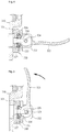
- FIG. 3 is a side view illustrating the side clamp according to the present invention.
- the side clamp 300 includes a fixing plate 310 and a distance adjusting part 320.
- the fixing plate 300 is a device that is attached to the side of the upper frame 200 to protrude from the top of the upper frame 200 by a predetermined length and supports the sides of the plurality of stacked glass plates. Such a fixing plate 300 has on a surface coming into contact with the glass plate an elastic plate 311 to absorb shocks.
- the elastic plate 311 may be made of any material as long as it has a predetermined elastic force and absorbs shocks when coming into contact with the glass plate.
- the elastic plate is preferably made of a rubber plate.
- An interleaf is inserted between the plurality of stacked glass plates to prevent the glass plates from coming into contact with each other. Since an area of the interleaf is larger than that of the glass plate, the interleaf protruding out from the glass plate prevents the side clamp 300 from coming into direct contact with the glass plate. However, if the side clamp 300 is strongly compressed, the glass plate may be damaged. In order to prevent the glass plate from being damaged, the elastic plate 311 is provided.
- the side clamp 300 is provided to reduce a gap between the side clamp and the side of the glass plate as small as possible, in consideration of the areas of the upper frame 200 and the glass plate.
- a certain gap may inevitably occur to allow the glass plate to be inserted.
- shocks may be transmitted, if any, to the glass plate due to vibrations and external shocks.
- the distance adjusting part 320 is provided, which makes the side clamp 300 approach the glass plate as near as possible after the glass plates have been stacked up, thus minimizing the gap between the glass plate and the side clamp 300.
- the fixing plate 300 is fixed to be movable horizontally while having a predetermined gap between the fixing plate and the side of the upper frame 200, by a linear shaft 328 that will be described later.
- the distance adjusting part 320 is a device that is provided on a lower portion of the fixing plate 300, preferably, a predetermined position of a surface of the fixing plate 300 that is opposite to the other surface of the fixing plate 300 coming into contact with the upper frame 200 to cause the fixing plate 300 to approach or move away from the glass plate.
- Such a distance adjusting part 320 mainly includes a base plate 321, a washer 323, an operation part, a curved washer, an elastic part 327, and a linear shaft 328.
- the base plate 321 is a device that is provided on a lower portion of a surface that is opposite to the other surface of the fixing plate 300 coupled to the upper frame 200 to define a space for accommodating components of the distance adjusting part 320.
- Such a base plate 321 is formed in the shape of a flat plate, and has at a central portion thereof a through-hole to allow the linear shaft 328 to pass therethrough.
- the washer 323 is a device that is inserted into the through-hole formed in the central portion of the base plate 321 and defines a space to allow the curved washer or the like to be stably seated therein.
- a washer 323 may be a flat washer, but preferably may be a recessed washer to allow the inserted curved washer to be fixed without being changed in position by the operation of the operation part.
- the elastic part 327 is a device that is provided on a predetermined portion of a lower surface or an upper surface of the washer 323 to make the fixing plate 300 approach or move away from the glass plate while being kept compressed or released by the operation of the operation part.
- Such an elastic part 327 may be made of any material as long as it has a predetermined elastic force.
- the elastic part may be preferably a spring, and more preferably a leaf spring or a plate spring.
- the elastic part 327 may be provided on the lower surface of the washer 323 to be entirely compressed by the compression of the washer 323, thus allowing external force to be evenly transmitted from the operation part to the elastic part.
- the operation part is a device that applies or removes external force to or from the elastic part 327 by a user's operation, thus compressing or releasing the elastic part 327.
- the operation part may employ any device as long as it achieves an intended purpose. The configuration of the operation part according to an embodiment will be described in more detail.
- the operation part may include a support part 322, a rotating shaft 324, and a lever part 325.
- the support part 322 is a pair of plate-shaped members that protrude from a surface of the base plate 321 to face each other.
- the pair of support parts 322 is provided to be symmetric with respect to a center of the through-hole formed at the center of the base plate 321.
- the rotating shaft 324 passes through the pair of support parts 322 and then is fixed, thus serving as the rotation center of the lever part 325.
- FIGS. 4 and 5 are views illustrating the use of the distance adjusting part according to the present invention.
- the lever part 325 is provided to be rotatable about the rotating shaft 324, and has on a portion coupled with the rotating shaft 324 a cam shape to adjust the compression and release of the elastic part 327 depending on the rotating angle.
- the portion of the lever part coupled with the rotating shaft 324 has the cam shape, it is possible to compress or release the elastic part 327 by operating the lever part 325, as illustrated in FIGS. 4 and 5 .
- the driving of the elastic part 327 and the driving of the fixing plate 300 by the operation part will be described below in more detail.
- the curved washer having on a surface thereof a curved surface may be provided between the lever part 325 and the washer 323 to more easily and evenly transmit external force transmitted by the cam shape of the lever part 325 to the washer 323 and the elastic part 327. Since the surface of the curved washer has the curved surface corresponding to the cam shape of the lever part 325, like the neck washer 326, it is easy to operate the lever part 325, and it is possible to evenly transmit the external force transmitted by the cam shape to the washer 323 and the elastic part 327. According to an intended use, it is possible to use a plate-shaped member made of an elastic material that may be flexibly deformed in conformity with the cam shape of the lever part 325, instead of the neck washer 326.
- One end of the linear shaft 328 passes through the fixing plate 300 to be inserted into the side of the upper frame 200, while the other end is fixed to the elastic part 327 or the rotating shaft 324 of the operation part.
- the linear shaft causes the fixing plate 300 to approach or move away from the glass plate.
- the linear shaft 328 may be fixed to a side of the elastic part 327 according to an intended use.
- the elastic part 327 is kept released.
- the fixing plate 300 is spaced apart from the side of the glass plate by a predetermined distance, thus allowing the glass plate to be easily seated and stacked on the upper frame 200.
- the lever part 325 of the operation part is rotated in one direction. Then, as the external force is transmitted to the neck washer 326, the washer 323 and the elastic part 327 by the cam shape of the lever part 325, the elastic part 327 is compressed and the linear shaft 328 is pulled out from the upper frame 200. If the linear shaft 328 is pulled out from the upper frame 200 as such, the fixing plate 300 approaches the upper frame 200 and comes into close contact with the side of the glass plate, thus preventing the glass plate from being shaken and vibrated. In the state where the side clamp 300 is compressed, the glass plate is stably fixed by the elasticity of the rubber plate provided inside the fixing plate 300, and vibrations and shocks transmitted to the glass plate are minimized.
- the lever part 325 is rotated in the other direction. Then, the elastic part 327 is released and the linear shaft 328 moves inwards relative to the upper frame 200, and the fixing plate 300 generates the gap between it and the upper frame 200. As such, the gap is generated between the fixing plate 300 and the glass plate, thus making it easy to unload the glass plate.
- a one-touch button may be employed to compress and release the elastic part 327, instead of the lever part, according to an intended use. Further, devices other than the one-touch button may be used as long as they fulfill the intended use.
- a plurality of distance adjusting parts 320 configured as described above may be provided on a side of the fixing plate 300 to allow the fixing plate 300 to stably and uniformly approach or move away from the glass plate. Although it is shown in the drawings that two distance adjusting parts 320 are provided on one fixing plate 300, it is apparent that a single distance adjusting part 320 or two or more distance adjusting parts 320 may be provided according to an intended use.
- a side of the lower frame 100 may be fixed and then lifted and transferred by a transfer arm.
- the lower frame 100 has on a side thereof a plurality of support columns to stack the plurality of pallets 10 while separating them from each other at a predetermined interval, thus allowing a great number of glass plates to be simultaneously conveyed. Since such a lower frame 100 is usually used in the art, a detailed description thereof will be omitted herein.
- shock absorbers may be provided between the lower frame 100 and the upper frame 200 to mitigate external shocks and vibrations.
- the shock absorber may easily mitigate external shocks and vibrations, it may be made of any material and may have any shape.
Landscapes
- Engineering & Computer Science (AREA)
- Mechanical Engineering (AREA)
- Packaging Frangible Articles (AREA)
- Pallets (AREA)
Applications Claiming Priority (2)
| Application Number | Priority Date | Filing Date | Title |
|---|---|---|---|
| KR1020140187129A KR101548698B1 (ko) | 2014-12-23 | 2014-12-23 | 유리판 이송 팔레트 |
| PCT/KR2015/014020 WO2016105049A1 (ko) | 2014-12-23 | 2015-12-21 | 유리판 이송 팔레트 |
Publications (4)
| Publication Number | Publication Date |
|---|---|
| EP3239065A1 true EP3239065A1 (de) | 2017-11-01 |
| EP3239065A4 EP3239065A4 (de) | 2018-08-08 |
| EP3239065B1 EP3239065B1 (de) | 2019-09-18 |
| EP3239065B8 EP3239065B8 (de) | 2019-10-23 |
Family
ID=54246784
Family Applications (1)
| Application Number | Title | Priority Date | Filing Date |
|---|---|---|---|
| EP15873576.1A Not-in-force EP3239065B8 (de) | 2014-12-23 | 2015-12-21 | Palette zum transportieren einer glasplatte |
Country Status (5)
| Country | Link |
|---|---|
| US (1) | US20170341853A1 (de) |
| EP (1) | EP3239065B8 (de) |
| KR (1) | KR101548698B1 (de) |
| CN (1) | CN107108069B (de) |
| WO (1) | WO2016105049A1 (de) |
Cited By (1)
| Publication number | Priority date | Publication date | Assignee | Title |
|---|---|---|---|---|
| US11892018B2 (en) | 2019-07-30 | 2024-02-06 | Crateight Limited | Apparatus for holding artwork |
Families Citing this family (4)
| Publication number | Priority date | Publication date | Assignee | Title |
|---|---|---|---|---|
| CN209506380U (zh) * | 2018-12-05 | 2019-10-18 | 惠科股份有限公司 | 一种栈板和包装装置 |
| KR101988366B1 (ko) * | 2019-01-31 | 2019-06-12 | 임재열 | 판유리 이송 장치 |
| JP7539699B2 (ja) * | 2020-12-21 | 2024-08-26 | 株式会社ダイワ | シート状の物品の搬送方法 |
| CN114873270B (zh) * | 2022-05-31 | 2025-07-18 | 嘉兴市大明实业有限公司 | 一种光伏玻璃板快装式托架 |
Family Cites Families (13)
| Publication number | Priority date | Publication date | Assignee | Title |
|---|---|---|---|---|
| DE3607766C1 (en) * | 1986-03-08 | 1987-05-27 | Parke Davis & Co | Object clamping-in device for a microtome |
| JP5182283B2 (ja) * | 2007-02-26 | 2013-04-17 | 旭硝子株式会社 | 板状体の梱包パレット |
| JP2009154960A (ja) * | 2007-12-28 | 2009-07-16 | Asahi Glass Co Ltd | 板状体収納容器 |
| JP5251136B2 (ja) * | 2008-01-16 | 2013-07-31 | 旭硝子株式会社 | 板状体の積載装置及び運搬車両 |
| KR100961203B1 (ko) * | 2008-04-29 | 2010-06-09 | 주식회사 하이닉스반도체 | 스페이서 패터닝 기술을 이용한 미세 패턴 형성 방법 |
| JP5423969B2 (ja) | 2009-04-27 | 2014-02-19 | 旭硝子株式会社 | 板状体の収納容器及び収納体 |
| JP2011063284A (ja) | 2009-09-16 | 2011-03-31 | Asahi Glass Co Ltd | ガラス板搬送用パレット |
| JP3166374U (ja) * | 2010-12-20 | 2011-03-03 | 旭硝子株式会社 | 板状体収納容器 |
| JP2012131549A (ja) * | 2010-12-22 | 2012-07-12 | Asahi Glass Co Ltd | 梱包容器および梱包体 |
| JP5139561B2 (ja) * | 2011-03-10 | 2013-02-06 | 三協立山株式会社 | 搬送パレット |
| JP5939748B2 (ja) * | 2011-07-01 | 2016-06-22 | 三協立山株式会社 | 搬送パレットのパネル保持板のパネル保持台への取り付け方法 |
| JP2013107686A (ja) * | 2011-11-22 | 2013-06-06 | Asahi Glass Co Ltd | ガラス板梱包体のガラス板押え装置 |
| JP5534085B2 (ja) * | 2013-06-07 | 2014-06-25 | 日本電気硝子株式会社 | ガラス板梱包体 |
-
2014
- 2014-12-23 KR KR1020140187129A patent/KR101548698B1/ko not_active Expired - Fee Related
-
2015
- 2015-12-21 EP EP15873576.1A patent/EP3239065B8/de not_active Not-in-force
- 2015-12-21 WO PCT/KR2015/014020 patent/WO2016105049A1/ko not_active Ceased
- 2015-12-21 US US15/538,660 patent/US20170341853A1/en not_active Abandoned
- 2015-12-21 CN CN201580070887.4A patent/CN107108069B/zh not_active Expired - Fee Related
Cited By (1)
| Publication number | Priority date | Publication date | Assignee | Title |
|---|---|---|---|---|
| US11892018B2 (en) | 2019-07-30 | 2024-02-06 | Crateight Limited | Apparatus for holding artwork |
Also Published As
| Publication number | Publication date |
|---|---|
| CN107108069B (zh) | 2019-02-01 |
| KR101548698B1 (ko) | 2015-09-01 |
| US20170341853A1 (en) | 2017-11-30 |
| WO2016105049A1 (ko) | 2016-06-30 |
| CN107108069A (zh) | 2017-08-29 |
| EP3239065B1 (de) | 2019-09-18 |
| EP3239065B8 (de) | 2019-10-23 |
| EP3239065A4 (de) | 2018-08-08 |
Similar Documents
| Publication | Publication Date | Title |
|---|---|---|
| EP3239065B1 (de) | Palette zum transportieren einer glasplatte | |
| US7857140B2 (en) | Semiconductor wafer storage case and semiconductor wafer storing method | |
| EP2903072B1 (de) | Blattmaterial-haftmittelanwendungsverfahren | |
| US9381653B2 (en) | Robot and substrate handling apparatus including the same | |
| US20130141717A1 (en) | Piezoelectric motor, driving device, electronic component conveying device, electronic component inspection device, printing device, robot hand, and robot | |
| CN210364828U (zh) | 防振托盘以及玻璃捆包体 | |
| KR101511731B1 (ko) | 웨이퍼 운반장치 | |
| JP4329536B2 (ja) | 半導体ウェハーの収納具 | |
| JP5070651B2 (ja) | リニアフィーダ | |
| WO2011001472A1 (ja) | 移載装置 | |
| KR102649102B1 (ko) | 유리판 곤포용 펠릿 및 유리판 곤포체 | |
| JP7012942B2 (ja) | 積層体パレット一体品、及びパレット | |
| KR20250023269A (ko) | 하향 압력을 흡수하기 위한 레티클 지지대가 제공된 레티클 포드 | |
| CN105102347A (zh) | 包装弹性压环 | |
| CN106468497B (zh) | 一种搁架组件及包括其的冰箱 | |
| CN205608386U (zh) | 掩膜板卡夹 | |
| KR101045622B1 (ko) | 편광판 공급장치용 카세트 및 이를 포함하는 편광판 공급장치 | |
| JPH03503329A (ja) | 整列装置 | |
| CN208631464U (zh) | 可调整驱动力的压电振动送料器 | |
| KR101867273B1 (ko) | 전자부품용 로딩 유닛 및 그 제어방법 | |
| JP7750627B2 (ja) | トップオープンタイプの基板容器の保持装置 | |
| CN213893077U (zh) | 一种拾取设备的输送装置 | |
| KR102892575B1 (ko) | 다단 적재 트레이 정렬장치 및 이를 포함하는 다단 적재 트레이 정렬 시스템 | |
| KR101431179B1 (ko) | 피치 가변에 따른 피커의 흔들림 방지 구조 | |
| JP6481091B1 (ja) | スペーサー |
Legal Events
| Date | Code | Title | Description |
|---|---|---|---|
| STAA | Information on the status of an ep patent application or granted ep patent |
Free format text: STATUS: THE INTERNATIONAL PUBLICATION HAS BEEN MADE |
|
| PUAI | Public reference made under article 153(3) epc to a published international application that has entered the european phase |
Free format text: ORIGINAL CODE: 0009012 |
|
| STAA | Information on the status of an ep patent application or granted ep patent |
Free format text: STATUS: REQUEST FOR EXAMINATION WAS MADE |
|
| 17P | Request for examination filed |
Effective date: 20170706 |
|
| AK | Designated contracting states |
Kind code of ref document: A1 Designated state(s): AL AT BE BG CH CY CZ DE DK EE ES FI FR GB GR HR HU IE IS IT LI LT LU LV MC MK MT NL NO PL PT RO RS SE SI SK SM TR |
|
| AX | Request for extension of the european patent |
Extension state: BA ME |
|
| DAV | Request for validation of the european patent (deleted) | ||
| DAX | Request for extension of the european patent (deleted) | ||
| A4 | Supplementary search report drawn up and despatched |
Effective date: 20180711 |
|
| RIC1 | Information provided on ipc code assigned before grant |
Ipc: B65D 19/44 20060101AFI20180705BHEP Ipc: B65D 85/48 20060101ALI20180705BHEP |
|
| GRAP | Despatch of communication of intention to grant a patent |
Free format text: ORIGINAL CODE: EPIDOSNIGR1 |
|
| STAA | Information on the status of an ep patent application or granted ep patent |
Free format text: STATUS: GRANT OF PATENT IS INTENDED |
|
| INTG | Intention to grant announced |
Effective date: 20190416 |
|
| GRAS | Grant fee paid |
Free format text: ORIGINAL CODE: EPIDOSNIGR3 |
|
| GRAA | (expected) grant |
Free format text: ORIGINAL CODE: 0009210 |
|
| STAA | Information on the status of an ep patent application or granted ep patent |
Free format text: STATUS: THE PATENT HAS BEEN GRANTED |
|
| GRAT | Correction requested after decision to grant or after decision to maintain patent in amended form |
Free format text: ORIGINAL CODE: EPIDOSNCDEC |
|
| RAP1 | Party data changed (applicant data changed or rights of an application transferred) |
Owner name: LG CHEM, LTD. |
|
| AK | Designated contracting states |
Kind code of ref document: B1 Designated state(s): AL AT BE BG CH CY CZ DE DK EE ES FI FR GB GR HR HU IE IS IT LI LT LU LV MC MK MT NL NO PL PT RO RS SE SI SK SM TR |
|
| REG | Reference to a national code |
Ref country code: GB Ref legal event code: FG4D |
|
| REG | Reference to a national code |
Ref country code: CH Ref legal event code: EP Ref country code: CH Ref legal event code: PK Free format text: BERICHTIGUNG B8 |
|
| RAP2 | Party data changed (patent owner data changed or rights of a patent transferred) |
Owner name: LG CHEM, LTD. |
|
| REG | Reference to a national code |
Ref country code: AT Ref legal event code: REF Ref document number: 1181025 Country of ref document: AT Kind code of ref document: T Effective date: 20191015 |
|
| RAP2 | Party data changed (patent owner data changed or rights of a patent transferred) |
Owner name: LG CHEM, LTD. |
|
| REG | Reference to a national code |
Ref country code: IE Ref legal event code: FG4D |
|
| REG | Reference to a national code |
Ref country code: DE Ref legal event code: R096 Ref document number: 602015038483 Country of ref document: DE |
|
| REG | Reference to a national code |
Ref country code: NL Ref legal event code: MP Effective date: 20190918 |
|
| PG25 | Lapsed in a contracting state [announced via postgrant information from national office to epo] |
Ref country code: SE Free format text: LAPSE BECAUSE OF FAILURE TO SUBMIT A TRANSLATION OF THE DESCRIPTION OR TO PAY THE FEE WITHIN THE PRESCRIBED TIME-LIMIT Effective date: 20190918 Ref country code: BG Free format text: LAPSE BECAUSE OF FAILURE TO SUBMIT A TRANSLATION OF THE DESCRIPTION OR TO PAY THE FEE WITHIN THE PRESCRIBED TIME-LIMIT Effective date: 20191218 Ref country code: HR Free format text: LAPSE BECAUSE OF FAILURE TO SUBMIT A TRANSLATION OF THE DESCRIPTION OR TO PAY THE FEE WITHIN THE PRESCRIBED TIME-LIMIT Effective date: 20190918 Ref country code: NO Free format text: LAPSE BECAUSE OF FAILURE TO SUBMIT A TRANSLATION OF THE DESCRIPTION OR TO PAY THE FEE WITHIN THE PRESCRIBED TIME-LIMIT Effective date: 20191218 Ref country code: LT Free format text: LAPSE BECAUSE OF FAILURE TO SUBMIT A TRANSLATION OF THE DESCRIPTION OR TO PAY THE FEE WITHIN THE PRESCRIBED TIME-LIMIT Effective date: 20190918 Ref country code: FI Free format text: LAPSE BECAUSE OF FAILURE TO SUBMIT A TRANSLATION OF THE DESCRIPTION OR TO PAY THE FEE WITHIN THE PRESCRIBED TIME-LIMIT Effective date: 20190918 |
|
| REG | Reference to a national code |
Ref country code: LT Ref legal event code: MG4D |
|
| PG25 | Lapsed in a contracting state [announced via postgrant information from national office to epo] |
Ref country code: LV Free format text: LAPSE BECAUSE OF FAILURE TO SUBMIT A TRANSLATION OF THE DESCRIPTION OR TO PAY THE FEE WITHIN THE PRESCRIBED TIME-LIMIT Effective date: 20190918 Ref country code: GR Free format text: LAPSE BECAUSE OF FAILURE TO SUBMIT A TRANSLATION OF THE DESCRIPTION OR TO PAY THE FEE WITHIN THE PRESCRIBED TIME-LIMIT Effective date: 20191219 Ref country code: AL Free format text: LAPSE BECAUSE OF FAILURE TO SUBMIT A TRANSLATION OF THE DESCRIPTION OR TO PAY THE FEE WITHIN THE PRESCRIBED TIME-LIMIT Effective date: 20190918 Ref country code: RS Free format text: LAPSE BECAUSE OF FAILURE TO SUBMIT A TRANSLATION OF THE DESCRIPTION OR TO PAY THE FEE WITHIN THE PRESCRIBED TIME-LIMIT Effective date: 20190918 |
|
| REG | Reference to a national code |
Ref country code: AT Ref legal event code: MK05 Ref document number: 1181025 Country of ref document: AT Kind code of ref document: T Effective date: 20190918 |
|
| PG25 | Lapsed in a contracting state [announced via postgrant information from national office to epo] |
Ref country code: AT Free format text: LAPSE BECAUSE OF FAILURE TO SUBMIT A TRANSLATION OF THE DESCRIPTION OR TO PAY THE FEE WITHIN THE PRESCRIBED TIME-LIMIT Effective date: 20190918 Ref country code: PL Free format text: LAPSE BECAUSE OF FAILURE TO SUBMIT A TRANSLATION OF THE DESCRIPTION OR TO PAY THE FEE WITHIN THE PRESCRIBED TIME-LIMIT Effective date: 20190918 Ref country code: NL Free format text: LAPSE BECAUSE OF FAILURE TO SUBMIT A TRANSLATION OF THE DESCRIPTION OR TO PAY THE FEE WITHIN THE PRESCRIBED TIME-LIMIT Effective date: 20190918 Ref country code: ES Free format text: LAPSE BECAUSE OF FAILURE TO SUBMIT A TRANSLATION OF THE DESCRIPTION OR TO PAY THE FEE WITHIN THE PRESCRIBED TIME-LIMIT Effective date: 20190918 Ref country code: RO Free format text: LAPSE BECAUSE OF FAILURE TO SUBMIT A TRANSLATION OF THE DESCRIPTION OR TO PAY THE FEE WITHIN THE PRESCRIBED TIME-LIMIT Effective date: 20190918 Ref country code: IT Free format text: LAPSE BECAUSE OF FAILURE TO SUBMIT A TRANSLATION OF THE DESCRIPTION OR TO PAY THE FEE WITHIN THE PRESCRIBED TIME-LIMIT Effective date: 20190918 Ref country code: EE Free format text: LAPSE BECAUSE OF FAILURE TO SUBMIT A TRANSLATION OF THE DESCRIPTION OR TO PAY THE FEE WITHIN THE PRESCRIBED TIME-LIMIT Effective date: 20190918 Ref country code: PT Free format text: LAPSE BECAUSE OF FAILURE TO SUBMIT A TRANSLATION OF THE DESCRIPTION OR TO PAY THE FEE WITHIN THE PRESCRIBED TIME-LIMIT Effective date: 20200120 |
|
| PG25 | Lapsed in a contracting state [announced via postgrant information from national office to epo] |
Ref country code: IS Free format text: LAPSE BECAUSE OF FAILURE TO SUBMIT A TRANSLATION OF THE DESCRIPTION OR TO PAY THE FEE WITHIN THE PRESCRIBED TIME-LIMIT Effective date: 20200224 Ref country code: SM Free format text: LAPSE BECAUSE OF FAILURE TO SUBMIT A TRANSLATION OF THE DESCRIPTION OR TO PAY THE FEE WITHIN THE PRESCRIBED TIME-LIMIT Effective date: 20190918 Ref country code: SK Free format text: LAPSE BECAUSE OF FAILURE TO SUBMIT A TRANSLATION OF THE DESCRIPTION OR TO PAY THE FEE WITHIN THE PRESCRIBED TIME-LIMIT Effective date: 20190918 Ref country code: CZ Free format text: LAPSE BECAUSE OF FAILURE TO SUBMIT A TRANSLATION OF THE DESCRIPTION OR TO PAY THE FEE WITHIN THE PRESCRIBED TIME-LIMIT Effective date: 20190918 |
|
| REG | Reference to a national code |
Ref country code: DE Ref legal event code: R097 Ref document number: 602015038483 Country of ref document: DE |
|
| PLBE | No opposition filed within time limit |
Free format text: ORIGINAL CODE: 0009261 |
|
| STAA | Information on the status of an ep patent application or granted ep patent |
Free format text: STATUS: NO OPPOSITION FILED WITHIN TIME LIMIT |
|
| PG2D | Information on lapse in contracting state deleted |
Ref country code: IS |
|
| PG25 | Lapsed in a contracting state [announced via postgrant information from national office to epo] |
Ref country code: DK Free format text: LAPSE BECAUSE OF FAILURE TO SUBMIT A TRANSLATION OF THE DESCRIPTION OR TO PAY THE FEE WITHIN THE PRESCRIBED TIME-LIMIT Effective date: 20190918 Ref country code: IS Free format text: LAPSE BECAUSE OF FAILURE TO SUBMIT A TRANSLATION OF THE DESCRIPTION OR TO PAY THE FEE WITHIN THE PRESCRIBED TIME-LIMIT Effective date: 20200119 |
|
| REG | Reference to a national code |
Ref country code: CH Ref legal event code: PL |
|
| 26N | No opposition filed |
Effective date: 20200619 |
|
| REG | Reference to a national code |
Ref country code: BE Ref legal event code: MM Effective date: 20191231 |
|
| PG25 | Lapsed in a contracting state [announced via postgrant information from national office to epo] |
Ref country code: MC Free format text: LAPSE BECAUSE OF FAILURE TO SUBMIT A TRANSLATION OF THE DESCRIPTION OR TO PAY THE FEE WITHIN THE PRESCRIBED TIME-LIMIT Effective date: 20190918 Ref country code: SI Free format text: LAPSE BECAUSE OF FAILURE TO SUBMIT A TRANSLATION OF THE DESCRIPTION OR TO PAY THE FEE WITHIN THE PRESCRIBED TIME-LIMIT Effective date: 20190918 |
|
| PG25 | Lapsed in a contracting state [announced via postgrant information from national office to epo] |
Ref country code: IE Free format text: LAPSE BECAUSE OF NON-PAYMENT OF DUE FEES Effective date: 20191221 Ref country code: LU Free format text: LAPSE BECAUSE OF NON-PAYMENT OF DUE FEES Effective date: 20191221 |
|
| PG25 | Lapsed in a contracting state [announced via postgrant information from national office to epo] |
Ref country code: BE Free format text: LAPSE BECAUSE OF NON-PAYMENT OF DUE FEES Effective date: 20191231 Ref country code: LI Free format text: LAPSE BECAUSE OF NON-PAYMENT OF DUE FEES Effective date: 20191231 Ref country code: CH Free format text: LAPSE BECAUSE OF NON-PAYMENT OF DUE FEES Effective date: 20191231 |
|
| PG25 | Lapsed in a contracting state [announced via postgrant information from national office to epo] |
Ref country code: CY Free format text: LAPSE BECAUSE OF FAILURE TO SUBMIT A TRANSLATION OF THE DESCRIPTION OR TO PAY THE FEE WITHIN THE PRESCRIBED TIME-LIMIT Effective date: 20190918 |
|
| PG25 | Lapsed in a contracting state [announced via postgrant information from national office to epo] |
Ref country code: HU Free format text: LAPSE BECAUSE OF FAILURE TO SUBMIT A TRANSLATION OF THE DESCRIPTION OR TO PAY THE FEE WITHIN THE PRESCRIBED TIME-LIMIT; INVALID AB INITIO Effective date: 20151221 Ref country code: MT Free format text: LAPSE BECAUSE OF FAILURE TO SUBMIT A TRANSLATION OF THE DESCRIPTION OR TO PAY THE FEE WITHIN THE PRESCRIBED TIME-LIMIT Effective date: 20190918 |
|
| PG25 | Lapsed in a contracting state [announced via postgrant information from national office to epo] |
Ref country code: TR Free format text: LAPSE BECAUSE OF FAILURE TO SUBMIT A TRANSLATION OF THE DESCRIPTION OR TO PAY THE FEE WITHIN THE PRESCRIBED TIME-LIMIT Effective date: 20190918 |
|
| PG25 | Lapsed in a contracting state [announced via postgrant information from national office to epo] |
Ref country code: MK Free format text: LAPSE BECAUSE OF FAILURE TO SUBMIT A TRANSLATION OF THE DESCRIPTION OR TO PAY THE FEE WITHIN THE PRESCRIBED TIME-LIMIT Effective date: 20190918 |
|
| PGFP | Annual fee paid to national office [announced via postgrant information from national office to epo] |
Ref country code: GB Payment date: 20231120 Year of fee payment: 9 |
|
| PGFP | Annual fee paid to national office [announced via postgrant information from national office to epo] |
Ref country code: FR Payment date: 20231121 Year of fee payment: 9 Ref country code: DE Payment date: 20231120 Year of fee payment: 9 |
|
| REG | Reference to a national code |
Ref country code: DE Ref legal event code: R119 Ref document number: 602015038483 Country of ref document: DE |
|
| GBPC | Gb: european patent ceased through non-payment of renewal fee |
Effective date: 20241221 |
|
| PG25 | Lapsed in a contracting state [announced via postgrant information from national office to epo] |
Ref country code: DE Free format text: LAPSE BECAUSE OF NON-PAYMENT OF DUE FEES Effective date: 20250701 |
|
| PG25 | Lapsed in a contracting state [announced via postgrant information from national office to epo] |
Ref country code: GB Free format text: LAPSE BECAUSE OF NON-PAYMENT OF DUE FEES Effective date: 20241221 |
|
| PG25 | Lapsed in a contracting state [announced via postgrant information from national office to epo] |
Ref country code: FR Free format text: LAPSE BECAUSE OF NON-PAYMENT OF DUE FEES Effective date: 20241231 |