EP3239097A1 - Brennstoffzellenelement - Google Patents
Brennstoffzellenelement Download PDFInfo
- Publication number
- EP3239097A1 EP3239097A1 EP16167062.5A EP16167062A EP3239097A1 EP 3239097 A1 EP3239097 A1 EP 3239097A1 EP 16167062 A EP16167062 A EP 16167062A EP 3239097 A1 EP3239097 A1 EP 3239097A1
- Authority
- EP
- European Patent Office
- Prior art keywords
- fuel cell
- unit
- water
- fuel
- reformer
- Prior art date
- Legal status (The legal status is an assumption and is not a legal conclusion. Google has not performed a legal analysis and makes no representation as to the accuracy of the status listed.)
- Granted
Links
Images

Classifications
-
- C—CHEMISTRY; METALLURGY
- C01—INORGANIC CHEMISTRY
- C01B—NON-METALLIC ELEMENTS; COMPOUNDS THEREOF; METALLOIDS OR COMPOUNDS THEREOF NOT COVERED BY SUBCLASS C01C
- C01B3/00—Hydrogen; Gaseous mixtures containing hydrogen; Separation of hydrogen from mixtures containing it; Purification of hydrogen; Reversible storage of hydrogen
- C01B3/02—Production of hydrogen; Production of gaseous mixtures containing hydrogen
- C01B3/32—Production of hydrogen; Production of gaseous mixtures containing hydrogen by reaction of gaseous or liquid organic compounds with gasifying agents, e.g. water, carbon dioxide or air
- C01B3/34—Production of hydrogen; Production of gaseous mixtures containing hydrogen by reaction of gaseous or liquid organic compounds with gasifying agents, e.g. water, carbon dioxide or air by reaction of hydrocarbons with gasifying agents
-
- H—ELECTRICITY
- H01—ELECTRIC ELEMENTS
- H01M—PROCESSES OR MEANS, e.g. BATTERIES, FOR THE DIRECT CONVERSION OF CHEMICAL ENERGY INTO ELECTRICAL ENERGY
- H01M8/00—Fuel cells; Manufacture thereof
- H01M8/04—Auxiliary arrangements, e.g. for control of pressure or for circulation of fluids
- H01M8/04298—Processes for controlling fuel cells or fuel cell systems
- H01M8/04694—Processes for controlling fuel cells or fuel cell systems characterised by variables to be controlled
- H01M8/04955—Shut-off or shut-down of fuel cells
-
- H—ELECTRICITY
- H01—ELECTRIC ELEMENTS
- H01M—PROCESSES OR MEANS, e.g. BATTERIES, FOR THE DIRECT CONVERSION OF CHEMICAL ENERGY INTO ELECTRICAL ENERGY
- H01M8/00—Fuel cells; Manufacture thereof
- H01M8/06—Combination of fuel cells with means for production of reactants or for treatment of residues
- H01M8/0606—Combination of fuel cells with means for production of reactants or for treatment of residues with means for production of gaseous reactants
- H01M8/0612—Combination of fuel cells with means for production of reactants or for treatment of residues with means for production of gaseous reactants from carbon-containing material
- H01M8/0618—Reforming processes, e.g. autothermal, partial oxidation or steam reforming
-
- C—CHEMISTRY; METALLURGY
- C01—INORGANIC CHEMISTRY
- C01B—NON-METALLIC ELEMENTS; COMPOUNDS THEREOF; METALLOIDS OR COMPOUNDS THEREOF NOT COVERED BY SUBCLASS C01C
- C01B2203/00—Integrated processes for the production of hydrogen or synthesis gas
- C01B2203/02—Processes for making hydrogen or synthesis gas
- C01B2203/0205—Processes for making hydrogen or synthesis gas containing a reforming step
- C01B2203/0227—Processes for making hydrogen or synthesis gas containing a reforming step containing a catalytic reforming step
- C01B2203/0233—Processes for making hydrogen or synthesis gas containing a reforming step containing a catalytic reforming step the reforming step being a steam reforming step
-
- C—CHEMISTRY; METALLURGY
- C01—INORGANIC CHEMISTRY
- C01B—NON-METALLIC ELEMENTS; COMPOUNDS THEREOF; METALLOIDS OR COMPOUNDS THEREOF NOT COVERED BY SUBCLASS C01C
- C01B2203/00—Integrated processes for the production of hydrogen or synthesis gas
- C01B2203/06—Integration with other chemical processes
- C01B2203/066—Integration with other chemical processes with fuel cells
-
- C—CHEMISTRY; METALLURGY
- C01—INORGANIC CHEMISTRY
- C01B—NON-METALLIC ELEMENTS; COMPOUNDS THEREOF; METALLOIDS OR COMPOUNDS THEREOF NOT COVERED BY SUBCLASS C01C
- C01B2203/00—Integrated processes for the production of hydrogen or synthesis gas
- C01B2203/12—Feeding the process for making hydrogen or synthesis gas
- C01B2203/1288—Evaporation of one or more of the different feed components
-
- C—CHEMISTRY; METALLURGY
- C01—INORGANIC CHEMISTRY
- C01B—NON-METALLIC ELEMENTS; COMPOUNDS THEREOF; METALLOIDS OR COMPOUNDS THEREOF NOT COVERED BY SUBCLASS C01C
- C01B2203/00—Integrated processes for the production of hydrogen or synthesis gas
- C01B2203/16—Controlling the process
- C01B2203/1609—Shutting down the process
-
- Y—GENERAL TAGGING OF NEW TECHNOLOGICAL DEVELOPMENTS; GENERAL TAGGING OF CROSS-SECTIONAL TECHNOLOGIES SPANNING OVER SEVERAL SECTIONS OF THE IPC; TECHNICAL SUBJECTS COVERED BY FORMER USPC CROSS-REFERENCE ART COLLECTIONS [XRACs] AND DIGESTS
- Y02—TECHNOLOGIES OR APPLICATIONS FOR MITIGATION OR ADAPTATION AGAINST CLIMATE CHANGE
- Y02E—REDUCTION OF GREENHOUSE GAS [GHG] EMISSIONS, RELATED TO ENERGY GENERATION, TRANSMISSION OR DISTRIBUTION
- Y02E60/00—Enabling technologies; Technologies with a potential or indirect contribution to GHG emissions mitigation
- Y02E60/30—Hydrogen technology
- Y02E60/50—Fuel cells
Definitions
- Fuel cell device which is provided to be operated with a fluidic fuel, with a desulfurization unit, which is provided to desulfurize the fuel at least partially, with a reformer unit, which is provided for generating at least one fuel gas, and with a fuel cell unit, is already known.
- the invention is based on a fuel cell device, which is provided to be operated with a fluidic fuel, with a desulfurization unit, which is provided to desulfurize the fuel at least partially, with a reformer unit, which is provided for generating at least one fuel gas, and with a fuel cell unit.
- the fuel cell device comprises a water supply unit, which is provided for supplying water at least temporarily to the reformer unit at least when shutting down the fuel cell unit.
- a “fuel cell device” is to be understood in particular a functional component, in particular a structural and/or functioning component of a fuel cell system.
- a “fuel cell system” is to be understood as a system provided for stationary and/or mobile generation of in particular electrical and/or thermal energy by using at least one fuel cell unit.
- “Provided” is to be understood in particular as specifically programmed, designed and/or equipped.
- a “fuel cell unit” is to be understood a unit with at least one fuel cell, which is provided for converting at least a chemical reaction energy of at least one in particular continuously supplied fuel gas, in particular hydrogen and/or carbon monoxide, and at least one oxidizing agent, in particular oxygen from air, into electrical and/or thermal energy.
- the at least one fuel cell may be embodied in particular as a solid oxide fuel cell (SOFC).
- SOFC solid oxide fuel cell
- the fuel cell unit comprises a plurality of fuel cells, which are in particular arranged in a fuel cell stack.
- a "desulfurization unit” is to be understood as a unit provided to reduce a volume and/or mole fraction of sulfur compounds in the fuel, in particular below a specified threshold value and preferably to remove a volume and/or mole fraction of sulfur compounds in the fuel at least substantially from the fuel, preferably by at least one physical and/or chemical adsorption and/or absorption process.
- a “reformer unit” is to be understood in particular a chemical-technical unit, which is provided for processing the fuel, in particular for generating a fuel gas containing gas mixture, in particular by partial oxidation and/or by an autothermal reforming and/or preferably by steam reforming.
- the reformer unit is embodied as a steam reformer unit.
- a steam reformer unit is to be understood in particular as a reformer unit provided to process the fuel by addition of water vapor for generation of the fuel gas containing gas mixture.
- a “water supply unit” is to be understood in particular a unit, which is provided for supplying water which is required for a reforming process to the reformer unit.
- the water supply unit is provided for supplying water continuously to the reformer unit.
- the water supply unit comprises at least one water supply pump provided for in particular continuous conveyance of the water.
- the water supply unit in particular comprises at least one vaporizer, which is fluidically arranged upstream of the reformer unit and which is provided for vaporizing the supplied water.
- the water supply unit is provided for keeping up the water supply of the reformer unit in particular for at least four hours, preferably for at least eight hours and especially preferred for at least twelve hours.
- a fuel cell device having advantageous operative features, in particular an enhanced shut down behavior, can be provided.
- materials of the desulfurization unit may absorb methane.
- the absorbed methane may be desorbed, which may lead to a coking of the reformer unit and/or the fuel cell unit if no water or an insufficient amount of water is supplied to the reformer unit.
- a water supply unit which is provided for supplying water at least temporarily to the reformer unit when shutting down the fuel cell unit, a sufficient amount of water can be supplied to the reformer unit even in case of a shutdown.
- coking of the reformer unit and/or the fuel cell unit can be advantageously reduced or preferably advantageously avoided.
- the water supply unit comprises at least one water reservoir, which is provided for providing water for supplying the reformer unit at least when shutting down the fuel cell unit.
- the water reservoir is provided for having a sufficient amount of water available for supplying the reformer unit when shutting down the fuel cell unit.
- the water reservoir is in particular provided to have at least 50 ml, preferably at least 100 ml and especially preferable at least 150 ml of water available for supplying the reformer unit when shutting down the fuel cell unit.
- the water reservoir comprises at least one water tank, which is provided for storing the water for supplying the reformer unit at least when shutting down the fuel cell unit.
- the water tank may be embodied at least partly as a rigid water tank.
- the water reservoir comprises at least one valve particularly a float valve, which is provided for releasing air from the water tank during filling the water tank and/or for letting in air into the water tank during emptying the water tank.
- the water tank may be embodied as a membrane expansion water tank or a spring-loaded water tank.
- a sufficient amount of water for supplying the reformer unit can be provided when shutting down the fuel cell unit.
- the water supply unit comprises at least one water storage pump, which is at least provided for filling the water reservoir at least partially with water during a normal operation of the fuel cell unit.
- the water storage pump is provided for filling the water reservoir completely during a normal operation of the fuel cell unit.
- the water supply pump is particularly provided for promoting water from a domestic water supply and/or from another water source to the water reservoir during a normal operation of the fuel cell unit.
- the water storage pump is embodied as an electrically driven water pump.
- the water storage pump is in particular driven by electrical energy provided by the fuel cell unit during a normal operation of the fuel cell unit.
- water for supplying the reformer unit can be advantageously stored during a normal operation of the fuel cell unit.
- the water reservoir is arranged above the reformer unit with respect to a common reference level.
- the common reference level may be a floor of an installation site of the fuel cell device.
- the water reservoir is connected via at least one at least substantially perpendicular orientated down pipe with at least one supply pipe of the reformer unit.
- the down pipe is at least substantially perpendicular to the common reference level.
- the water supply unit comprises at least one water supply pump, which is at least provided for continuously supplying water to the reformer unit during a normal operation of the fuel cell unit, and which comprises at least one energy storage, which is provided for supplying energy at least to the water supply pump when shutting down the fuel cell unit.
- the water supply pump is embodied as an electrically driven water pump.
- the water supply pump is in particular driven by electrical energy provided by the fuel cell unit during a normal operation of the fuel cell unit.
- the energy storage is provided for storing particularly electrical and/or mechanical energy for driving the water supply pump when shutting down the fuel cell unit.
- the energy storage is preferably embodied as electrical energy storage, e.g.
- the water supply pump When shutting down the fuel cell unit the water supply pump is in particular driven by electrical energy provided by the energy storage.
- the water supply pump is provided for promoting water from a domestic water supply to the reformer unit during a normal operation of the fuel cell unit.
- the water supply pump is provided for conveying water at least temporarily from a domestic water supply and/or another water source to the reformer unit when shutting down the fuel cell unit.
- the energy storage is provided for supplying energy to the water supply pump for at least four hours, preferably for at least eight hours and especially preferable for at least twelve hours.
- a sufficient amount of water for supplying the reformer unit can be provided when shutting down the fuel cell unit.
- the energy storage may be charged by an external power source, e.g. a domestic power supply.
- the energy storage is provided for storing electrical energy provided by the fuel cell unit during a normal operation of the fuel cell unit.
- the energy storage is preferably embodied as a rechargeable battery, a capacitor and/or a super capacitor.
- energy for supplying the water supply pump can be advantageously stored during a normal operation of the fuel cell unit.
- the water storage pump and the water supply pump are identical.
- the water storage pump and the water supply pump are integrally embodied as a single water pump, which is provided to carry out both functions.
- the single water pump in particular may be provided for simultaneously supplying water to the reformer unit and the water reservoir during a normal operation of the fuel cell unit.
- the single water pump in particular may be provided for supplying water to the reformer unit during a normal operation of the fuel cell unit and supplying at least temporarily water to the reformer unit when shutting down the fuel cell unit.
- a required number of water pumps can be advantageously reduced.
- a fuel cell system is proposed with at least one fuel cell device according to the invention.
- the fuel cell system may comprise further components and/or units such as supply pipes for fuel and/or air, flue pipes, heat exchangers, compressors, catalytic converters, compressors, and/or afterburners.
- supply pipes for fuel and/or air flue pipes, heat exchangers, compressors, catalytic converters, compressors, and/or afterburners.
- a method for operating a fuel cell device which is provided to be operated with a fluidic fuel, with a desulfurization unit, which is provided to desulfurize the fuel at least partially, with a reformer unit, which is provided for generating at least one fuel gas, and with a fuel cell unit, wherein the reformer unit is at least temporarily supplied with water when shutting down the fuel cell unit, is proposed.
- a sufficient amount of water can be supplied to the reformer unit even when shutting down the fuel cell unit.
- coking of the reformer unit and/or the fuel cell unit can be advantageously reduced or preferably advantageously avoided.
- the fuel cell device according to the invention is herein not to be restricted to the application and implementation described above.
- the fuel cell device according to the invention may comprise a number of individual elements, components and units, which differ from the number herein mentioned.
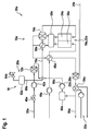
- FIG. 1 shows a schematic view of a fuel cell system 30a.
- the fuel cell system 30a comprises a fuel cell device 10a, which is provided to be operated with a fluidic fuel, in particular with natural gas. Alternatively, it is also conceivable to operate the fuel cell device 10a with another hydrocarbon containing in particular gaseous fuel such as biogas.
- the fuel cell device 10a comprises a fuel cell unit 16a.
- the fuel cell unit 16a is shown here simplified as a single fuel cell 32a. However, a fuel cell unit embodied as a fuel cell stack comprising a plurality of fuel cells is expedient.
- the fuel cell 32a is preferably embodied as a solid oxide fuel cell.
- the fuel cell 32a has an anode 34a and a cathode 36a.
- a fuel supply line 38a the fluidic fuel is fed to the fuel cell system 30a. Feed-in of the fluidic fuel can be controlled and/or regulated and/or entirely interrupted by a fuel valve 40a.
- the fuel valve 40a is preferably electro-magnetically actuatable.
- a fuel compressor 42a By means of a fuel compressor 42a a sufficient flow-rate of the fluidic fuel is ensured.
- Air is fed to a cathode 36a of the fuel cell unit 16a by means of a further compressor 44a or fan. Before entering the cathode 36a the air is preheated by a preheating unit 46a.
- the fuel cell device 10a comprises a desulfurization unit 12a.
- the desulfurization unit 12a is connected downstream of the fuel compressor 42a.
- the desulfurization unit 12a is provided to desulfurize the fluidic fuel.
- the fuel cell unit 10a further comprises a reformer unit 14a.
- the reformer unit 14a is provided for obtaining a hydrogen-rich fuel gas by processing the desulfurized fluidic fuel.
- the reformer unit 14a is embodied as a steam reformer unit.
- the hydrogen-rich gas leaving the reformer unit 14a is mainly fed to the anode 34a of the fuel cell unit 16a.
- the fuel cell device 10a further comprises a water supply unit 18a.
- the water supply unit 18a is provided for supplying water to the reformer unit 14a. Before entering the reformer unit 14a the water supplied is vaporized by a vaporizer unit 58a.
- the water supply unit 18a is provided for supplying water to the reformer unit 14a continuously during a normal operation of the fuel cell unit 16a.
- the water supply unit 18a comprises a water supply pump 26a provided for a continuous conveyance of the water from a water source 60a.
- the water source 60a can be a water tank that is filled either as shown by condensate water from the offgas line or by a connection to an external water supply.
- the water source may also contain a filter, for example a purifier, ion exchanger and/or a reverse osmosis unit.
- the water conveyed by the water supply pump 26a is mixed with the desulfurized fluidic fuel leaving the desulfurization unit 12a.
- materials of the desulfurization unit 12a may absorb methane.
- the absorbed methane may be desorbed, which may lead to a coking of the reformer unit 14a and/or the fuel cell unit 16a.
- the water supply unit 18a is provided for supplying water at least temporarily to the reformer unit 14a when shutting down the fuel cell unit 16a.
- the water supply unit 18a is provided for supplying water for at least twelve hours to the reformer unit 14a when shutting down the fuel cell unit 16a.
- the water supply unit 18a comprises a water reservoir 20a, which is provided for providing water for supplying the reformer unit 14a when shutting down the fuel cell unit.
- the water reservoir 20a is provided for having a sufficient amount of water available for supplying the reformer unit 14a when shutting down the fuel cell unit 16a.
- the water reservoir 20 is in particular provided for having at least 50 ml, preferable at least 100 ml and especially preferably at least 150 ml of water available for supplying the reformer unit 14a when shutting down the fuel cell unit 16a.
- the water reservoir 20a comprises a water tank 62a, which is provided for storing the water for supplying the reformer unit 14a when shutting down the fuel cell unit 16a.
- the water tank 62a may be embodied at least partly as a rigid water tank.
- the water reservoir 20a comprises at least one valve 64a particularly a float valve, which is provided for releasing air from the water tank 62a during the filling of the water tank 62a and/or for drawing air into the water tank 62a while emptying the water tank.
- the water supply unit 14a comprises a water storage pump 22a, which is provided for filling the water reservoir 20a with water during a normal operation of the fuel cell unit 16a.
- the water storage pump 22a and the water supply pump 26a are integrally embodied as a single water pump 66a, which is provided to carry out both functions.
- the single water pump 66a is provided for simultaneously supplying water to the reformer unit 14a and to the water reservoir 20a during a normal operation of the fuel cell unit 16a.
- the water reservoir 20a is arranged above the reformer unit 14a with respect to a common reference level 24a.
- the common reference level 24a may be a floor of an installation site of the fuel cell device 10a.
- the water reservoir 20a is connected via an at least substantially perpendicular orientated down pipe 68a with a supply pipe 70a of the reformer unit 14a.
- the down pipe 68a is at least substantially perpendicular to the common reference level 24a.
- the water reservoir 20a is supplied with water via the down pipe 68a.
- water is conveyed via the down pipe 68a to the supply pipe 70a of the reformer unit 14a by means of gravity.
- an exhaust gas of the anode 34a and air from the cathode 36a of the fuel cell unit 16a are fed to a combustion unit 50a in which an afterburning of combustible components remaining in the anode exhaust gas is effected.
- Thermal energy herein released is transferred, for example to a heating water circulation 52a via a heat exchanger 54a, to the reformer unit 14a, to the preheating unit 46a and/or to the vaporizer unit 58a.
- An exhaust gas is discharged via a chimney 56a.
- Figure 2 shows a further exemplary embodiment of the invention.
- the following descriptions and the drawings are essentially limited to the differences between the embodiments, wherein regarding equally designated components, in particular with regard to components with the same reference numerals, reference can be made to the drawings and/or the description of the embodiment of figure 1 .
- the letter a is attached to the reference numerals of the embodiment of figure 1 .
- the letter a is replaced by the letter b.
- FIG 2 shows a schematic view of a fuel cell system 30b.
- the fuel cell system 30b comprises an alternatively embodied fuel cell device 10b, which is provided to be operated with a fluidic fuel, in particular with natural gas. Alternatively, it is also conceivable to operate the fuel cell device 10b with another hydrocarbon containing in particular gaseous fuel such as biogas.
- the fuel cell device 10b comprises a fuel cell unit 16b.
- the fuel cell unit 16b is shown here simplified as a single fuel cell 32b. However a fuel cell unit embodied as a fuel cell stack comprising a plurality of fuel cells is expedient.
- the fuel cell 32b is preferably embodied as a solid oxide fuel cell.
- the fuel cell 32b has an anode 34b and a cathode 36b.
- the fluidic fuel is fed to the fuel cell system 30b. Feed-in of the fluidic fuel can be controlled and/or regulated and/or entirely interrupted by a fuel valve 40b.
- the fuel valve 40b is preferably electro-magnetically actuatable.
- a fuel compressor 42b By means of a fuel compressor 42b a sufficient flow-rate of the fluidic fuel is ensured.
- Air is fed to the cathode 36b of the fuel cell unit 16b by means of a further compressor 44b or fan. Before entering the cathode 36b the air is preheated by a preheating unit 46b.
- the fuel cell device 10b comprises a desulfurization unit 12b. The desulfurization unit 12b is connected downstream to the fuel compressor 42b.
- the desulfurization unit 12b is provided to desulfurize the fluidic fuel.
- the fuel cell unit 10b further comprises a reformer unit 14b.
- the reformer unit 14a is provided for obtaining a hydrogen-rich fuel gas by processing the desulfurized fluidic fuel.
- the reformer unit 14b is embodied as a steam reformer unit.
- the hydrogen-rich gas leaving the reformer unit 14b is mainly fed to the anode 34b of the fuel cell unit 16b.
- the fuel cell device 10b further comprises a water supply unit 18b.
- the water supply unit 18b is provided for supplying water to the reformer unit 14b. Before entering the reformer unit 14b the water supplied is vaporized by a vaporizer unit 58b.
- the water supply unit 18b is provided for supplying water to the reformer unit 14b continuously during a normal operation of the fuel cell unit 16b.
- the water supply unit 18b comprises a water supply pump 26b provided for a continuous conveyance of the water from a water source 60b.
- the water source 60b can be a water tank that is filled either as shown by condensate water from the offgas line or by a connection to an external water supply.
- the water source may also contain a filter, for example a purifier, ion exchanger and/or a reverse osmosis unit.
- the water promoted by the water supply pump 26b is mixed with the desulfurized fluidic fuel leaving the desulfurization unit 12b.
- materials of the desulfurization unit 12b may absorb methane.
- the absorbed methane may be desorbed, which may lead to a coking of the reformer unit 14b and/or the fuel cell unit 16b.
- the water supply unit 18b is provided for supplying water at least temporarily to the reformer unit 14b when shutting down the fuel cell unit 16b.
- the water supply unit 18b is provided for supplying water for at least twelve hours to the reformer unit 14b when shutting down the fuel cell unit 16b.
- the water supply pump 26b is embodied as an electrically driven water pump. The water supply pump 26b is in particular driven by electrical energy provided by the fuel cell unit 16b during a normal operation of the fuel cell unit 16b.
- the water supply unit 18b comprises an energy storage 28b, which is provided for supplying energy to the water supply pump 26b when shutting down the fuel cell unit 16b.
- the energy storage 28b is provided for storing electrical energy for driving the water supply pump 26b when shutting down the fuel cell unit 16a.
- the energy storage 28b is preferably embodied as electrical energy storage, e.g. as a battery, a rechargeable battery, a capacitor and/or a supercapacitor.
- the energy storage 28b is provided for storing electrical energy provided by the fuel cell unit 16b during a normal operation of the fuel cell unit 16b.
- the energy storage 28b is provided for supplying energy to the water supply pump 26b for at least twelve hours.
- an exhaust gas of the anode 34b and air from the cathode 36b of the fuel cell unit 16b are fed to a combustion unit 50b, in which an afterburning of combustible components remaining in the anode exhaust gas is effected.
- Thermal energy herein released is transferred, for example to a heating water circulation 52b via a heat exchanger 54b, to the reformer unit 14b, to the preheating unit 46b and/or to the vaporizer unit 58b.
- An exhaust gas is discharged via a chimney 56b.
Landscapes
- Chemical & Material Sciences (AREA)
- Chemical Kinetics & Catalysis (AREA)
- Engineering & Computer Science (AREA)
- Sustainable Development (AREA)
- Sustainable Energy (AREA)
- Life Sciences & Earth Sciences (AREA)
- Manufacturing & Machinery (AREA)
- Electrochemistry (AREA)
- General Chemical & Material Sciences (AREA)
- Organic Chemistry (AREA)
- Health & Medical Sciences (AREA)
- General Health & Medical Sciences (AREA)
- Combustion & Propulsion (AREA)
- Inorganic Chemistry (AREA)
- Fuel Cell (AREA)
Priority Applications (1)
| Application Number | Priority Date | Filing Date | Title |
|---|---|---|---|
| EP16167062.5A EP3239097B1 (de) | 2016-04-26 | 2016-04-26 | Brennstoffzellenelement |
Applications Claiming Priority (1)
| Application Number | Priority Date | Filing Date | Title |
|---|---|---|---|
| EP16167062.5A EP3239097B1 (de) | 2016-04-26 | 2016-04-26 | Brennstoffzellenelement |
Publications (2)
| Publication Number | Publication Date |
|---|---|
| EP3239097A1 true EP3239097A1 (de) | 2017-11-01 |
| EP3239097B1 EP3239097B1 (de) | 2019-02-13 |
Family
ID=55854634
Family Applications (1)
| Application Number | Title | Priority Date | Filing Date |
|---|---|---|---|
| EP16167062.5A Active EP3239097B1 (de) | 2016-04-26 | 2016-04-26 | Brennstoffzellenelement |
Country Status (1)
| Country | Link |
|---|---|
| EP (1) | EP3239097B1 (de) |
Cited By (2)
| Publication number | Priority date | Publication date | Assignee | Title |
|---|---|---|---|---|
| PL424261A1 (pl) * | 2018-01-12 | 2019-07-15 | Przedsiębiorstwo Innowacyjno-Wdrożeniowe Ekomotor Spółka Z Ograniczoną Odpowiedzialnością | Sposób i układ wytwarzania energii elektrycznej przy zastosowaniu reformingu parowego gazu zwłaszcza gazu zawierającego metan |
| JP2021064507A (ja) * | 2019-10-11 | 2021-04-22 | 京セラ株式会社 | 燃料電池装置、制御装置および制御プログラム |
Citations (4)
| Publication number | Priority date | Publication date | Assignee | Title |
|---|---|---|---|---|
| EP1753061A2 (de) * | 2005-06-30 | 2007-02-14 | Viessmann Werke GmbH & Co KG | Verfahren zum Starten und Abschalten einer Brennstoffzellenanlage |
| EP2256851A1 (de) * | 2009-05-28 | 2010-12-01 | Toto Ltd. | Festoxid-Brennstoffzellenvorrichtung |
| JP2012138186A (ja) * | 2010-12-24 | 2012-07-19 | Kyocera Corp | 高温作動型燃料電池システム |
| US20150044587A1 (en) * | 2012-04-09 | 2015-02-12 | Toto Ltd. | Solid oxide fuel cell system |
-
2016
- 2016-04-26 EP EP16167062.5A patent/EP3239097B1/de active Active
Patent Citations (4)
| Publication number | Priority date | Publication date | Assignee | Title |
|---|---|---|---|---|
| EP1753061A2 (de) * | 2005-06-30 | 2007-02-14 | Viessmann Werke GmbH & Co KG | Verfahren zum Starten und Abschalten einer Brennstoffzellenanlage |
| EP2256851A1 (de) * | 2009-05-28 | 2010-12-01 | Toto Ltd. | Festoxid-Brennstoffzellenvorrichtung |
| JP2012138186A (ja) * | 2010-12-24 | 2012-07-19 | Kyocera Corp | 高温作動型燃料電池システム |
| US20150044587A1 (en) * | 2012-04-09 | 2015-02-12 | Toto Ltd. | Solid oxide fuel cell system |
Cited By (3)
| Publication number | Priority date | Publication date | Assignee | Title |
|---|---|---|---|---|
| PL424261A1 (pl) * | 2018-01-12 | 2019-07-15 | Przedsiębiorstwo Innowacyjno-Wdrożeniowe Ekomotor Spółka Z Ograniczoną Odpowiedzialnością | Sposób i układ wytwarzania energii elektrycznej przy zastosowaniu reformingu parowego gazu zwłaszcza gazu zawierającego metan |
| JP2021064507A (ja) * | 2019-10-11 | 2021-04-22 | 京セラ株式会社 | 燃料電池装置、制御装置および制御プログラム |
| JP7284062B2 (ja) | 2019-10-11 | 2023-05-30 | 京セラ株式会社 | 燃料電池装置、制御装置および制御プログラム |
Also Published As
| Publication number | Publication date |
|---|---|
| EP3239097B1 (de) | 2019-02-13 |
Similar Documents
| Publication | Publication Date | Title |
|---|---|---|
| CN1037941C (zh) | 利用和回收燃烧废气中二氧化碳的方法和装置 | |
| JP5607302B2 (ja) | 加熱準備型水素生成燃料電池システム | |
| KR101572982B1 (ko) | 연료전지를 탑재한 선박의 폐열 회수 시스템 | |
| JP5133165B2 (ja) | 燃料電池システム | |
| CN1543686A (zh) | 零排放/低排放和共生产型能量供应站 | |
| EP2860804B1 (de) | Vorrichtung und Verfahren zur Erwärmung eines Brennstoffzellenstapels sowie Brennstoffzellensystem mit der Vorrichtung | |
| CN100527499C (zh) | 燃料电池系统 | |
| EP2452917B1 (de) | Brennstoffzellensystem | |
| EP2810326B1 (de) | Brennstoffzellenmodul | |
| WO2012066174A1 (es) | Ethanol processing system integrated in air - independant propulsion systems | |
| EP3239097B1 (de) | Brennstoffzellenelement | |
| KR102217612B1 (ko) | 연료 전지용 메탄올 개질 시스템, 이산화탄소 흡수식 탱크 시스템, 연료 및 반응수 저장 장치 및 이를 포함하는 해양 구조물 | |
| KR102535403B1 (ko) | 연료전지 및 이를 포함하는 선박 | |
| JP2002110207A (ja) | 燃料電池システムおよびその運転方法 | |
| JP5127395B2 (ja) | 燃料電池発電システム | |
| KR101788743B1 (ko) | 선박용 연료전지 시스템 | |
| JP4733479B2 (ja) | 液状炭化水素の脱硫装置を備える燃料電池システム | |
| RU2526851C1 (ru) | Энергоустановка на основе топливных элементов | |
| JP2009076392A (ja) | 液体燃料電池発電システム | |
| EP3240080B1 (de) | Brennstoffzellenvorrichtung | |
| JP2010024402A (ja) | 燃料電池発電システムおよびそれに用いる脱硫器 | |
| KR20200138520A (ko) | 연료 전지용 메탄올 개질 시스템, 이산화탄소 흡수식 탱크 시스템, 연료 및 반응수 저장 장치 및 이를 포함하는 해양 구조물 | |
| KR102190941B1 (ko) | 선박 | |
| KR102216751B1 (ko) | 연료 전지용 메탄올 개질 시스템, 이산화탄소 흡수식 탱크 시스템, 연료 및 반응수 저장 장치 및 이를 포함하는 해양 구조물 | |
| JP6080322B2 (ja) | 燃料電池システム |
Legal Events
| Date | Code | Title | Description |
|---|---|---|---|
| PUAI | Public reference made under article 153(3) epc to a published international application that has entered the european phase |
Free format text: ORIGINAL CODE: 0009012 |
|
| STAA | Information on the status of an ep patent application or granted ep patent |
Free format text: STATUS: THE APPLICATION HAS BEEN PUBLISHED |
|
| AK | Designated contracting states |
Kind code of ref document: A1 Designated state(s): AL AT BE BG CH CY CZ DE DK EE ES FI FR GB GR HR HU IE IS IT LI LT LU LV MC MK MT NL NO PL PT RO RS SE SI SK SM TR |
|
| AX | Request for extension of the european patent |
Extension state: BA ME |
|
| STAA | Information on the status of an ep patent application or granted ep patent |
Free format text: STATUS: REQUEST FOR EXAMINATION WAS MADE |
|
| 17P | Request for examination filed |
Effective date: 20180425 |
|
| RBV | Designated contracting states (corrected) |
Designated state(s): AL AT BE BG CH CY CZ DE DK EE ES FI FR GB GR HR HU IE IS IT LI LT LU LV MC MK MT NL NO PL PT RO RS SE SI SK SM TR |
|
| GRAP | Despatch of communication of intention to grant a patent |
Free format text: ORIGINAL CODE: EPIDOSNIGR1 |
|
| STAA | Information on the status of an ep patent application or granted ep patent |
Free format text: STATUS: GRANT OF PATENT IS INTENDED |
|
| INTG | Intention to grant announced |
Effective date: 20180912 |
|
| GRAS | Grant fee paid |
Free format text: ORIGINAL CODE: EPIDOSNIGR3 |
|
| GRAA | (expected) grant |
Free format text: ORIGINAL CODE: 0009210 |
|
| STAA | Information on the status of an ep patent application or granted ep patent |
Free format text: STATUS: THE PATENT HAS BEEN GRANTED |
|
| AK | Designated contracting states |
Kind code of ref document: B1 Designated state(s): AL AT BE BG CH CY CZ DE DK EE ES FI FR GB GR HR HU IE IS IT LI LT LU LV MC MK MT NL NO PL PT RO RS SE SI SK SM TR |
|
| REG | Reference to a national code |
Ref country code: GB Ref legal event code: FG4D |
|
| REG | Reference to a national code |
Ref country code: CH Ref legal event code: EP Ref country code: AT Ref legal event code: REF Ref document number: 1096093 Country of ref document: AT Kind code of ref document: T Effective date: 20190215 |
|
| REG | Reference to a national code |
Ref country code: IE Ref legal event code: FG4D |
|
| REG | Reference to a national code |
Ref country code: DE Ref legal event code: R096 Ref document number: 602016009879 Country of ref document: DE |
|
| REG | Reference to a national code |
Ref country code: LT Ref legal event code: MG4D |
|
| REG | Reference to a national code |
Ref country code: NL Ref legal event code: MP Effective date: 20190213 |
|
| PG25 | Lapsed in a contracting state [announced via postgrant information from national office to epo] |
Ref country code: FI Free format text: LAPSE BECAUSE OF FAILURE TO SUBMIT A TRANSLATION OF THE DESCRIPTION OR TO PAY THE FEE WITHIN THE PRESCRIBED TIME-LIMIT Effective date: 20190213 Ref country code: NO Free format text: LAPSE BECAUSE OF FAILURE TO SUBMIT A TRANSLATION OF THE DESCRIPTION OR TO PAY THE FEE WITHIN THE PRESCRIBED TIME-LIMIT Effective date: 20190513 Ref country code: LT Free format text: LAPSE BECAUSE OF FAILURE TO SUBMIT A TRANSLATION OF THE DESCRIPTION OR TO PAY THE FEE WITHIN THE PRESCRIBED TIME-LIMIT Effective date: 20190213 Ref country code: NL Free format text: LAPSE BECAUSE OF FAILURE TO SUBMIT A TRANSLATION OF THE DESCRIPTION OR TO PAY THE FEE WITHIN THE PRESCRIBED TIME-LIMIT Effective date: 20190213 Ref country code: SE Free format text: LAPSE BECAUSE OF FAILURE TO SUBMIT A TRANSLATION OF THE DESCRIPTION OR TO PAY THE FEE WITHIN THE PRESCRIBED TIME-LIMIT Effective date: 20190213 Ref country code: PT Free format text: LAPSE BECAUSE OF FAILURE TO SUBMIT A TRANSLATION OF THE DESCRIPTION OR TO PAY THE FEE WITHIN THE PRESCRIBED TIME-LIMIT Effective date: 20190613 |
|
| PG25 | Lapsed in a contracting state [announced via postgrant information from national office to epo] |
Ref country code: LV Free format text: LAPSE BECAUSE OF FAILURE TO SUBMIT A TRANSLATION OF THE DESCRIPTION OR TO PAY THE FEE WITHIN THE PRESCRIBED TIME-LIMIT Effective date: 20190213 Ref country code: RS Free format text: LAPSE BECAUSE OF FAILURE TO SUBMIT A TRANSLATION OF THE DESCRIPTION OR TO PAY THE FEE WITHIN THE PRESCRIBED TIME-LIMIT Effective date: 20190213 Ref country code: BG Free format text: LAPSE BECAUSE OF FAILURE TO SUBMIT A TRANSLATION OF THE DESCRIPTION OR TO PAY THE FEE WITHIN THE PRESCRIBED TIME-LIMIT Effective date: 20190513 Ref country code: IS Free format text: LAPSE BECAUSE OF FAILURE TO SUBMIT A TRANSLATION OF THE DESCRIPTION OR TO PAY THE FEE WITHIN THE PRESCRIBED TIME-LIMIT Effective date: 20190613 Ref country code: GR Free format text: LAPSE BECAUSE OF FAILURE TO SUBMIT A TRANSLATION OF THE DESCRIPTION OR TO PAY THE FEE WITHIN THE PRESCRIBED TIME-LIMIT Effective date: 20190514 Ref country code: HR Free format text: LAPSE BECAUSE OF FAILURE TO SUBMIT A TRANSLATION OF THE DESCRIPTION OR TO PAY THE FEE WITHIN THE PRESCRIBED TIME-LIMIT Effective date: 20190213 |
|
| REG | Reference to a national code |
Ref country code: AT Ref legal event code: MK05 Ref document number: 1096093 Country of ref document: AT Kind code of ref document: T Effective date: 20190213 |
|
| PG25 | Lapsed in a contracting state [announced via postgrant information from national office to epo] |
Ref country code: DK Free format text: LAPSE BECAUSE OF FAILURE TO SUBMIT A TRANSLATION OF THE DESCRIPTION OR TO PAY THE FEE WITHIN THE PRESCRIBED TIME-LIMIT Effective date: 20190213 Ref country code: EE Free format text: LAPSE BECAUSE OF FAILURE TO SUBMIT A TRANSLATION OF THE DESCRIPTION OR TO PAY THE FEE WITHIN THE PRESCRIBED TIME-LIMIT Effective date: 20190213 Ref country code: AL Free format text: LAPSE BECAUSE OF FAILURE TO SUBMIT A TRANSLATION OF THE DESCRIPTION OR TO PAY THE FEE WITHIN THE PRESCRIBED TIME-LIMIT Effective date: 20190213 Ref country code: SK Free format text: LAPSE BECAUSE OF FAILURE TO SUBMIT A TRANSLATION OF THE DESCRIPTION OR TO PAY THE FEE WITHIN THE PRESCRIBED TIME-LIMIT Effective date: 20190213 Ref country code: CZ Free format text: LAPSE BECAUSE OF FAILURE TO SUBMIT A TRANSLATION OF THE DESCRIPTION OR TO PAY THE FEE WITHIN THE PRESCRIBED TIME-LIMIT Effective date: 20190213 Ref country code: IT Free format text: LAPSE BECAUSE OF FAILURE TO SUBMIT A TRANSLATION OF THE DESCRIPTION OR TO PAY THE FEE WITHIN THE PRESCRIBED TIME-LIMIT Effective date: 20190213 Ref country code: ES Free format text: LAPSE BECAUSE OF FAILURE TO SUBMIT A TRANSLATION OF THE DESCRIPTION OR TO PAY THE FEE WITHIN THE PRESCRIBED TIME-LIMIT Effective date: 20190213 Ref country code: RO Free format text: LAPSE BECAUSE OF FAILURE TO SUBMIT A TRANSLATION OF THE DESCRIPTION OR TO PAY THE FEE WITHIN THE PRESCRIBED TIME-LIMIT Effective date: 20190213 |
|
| REG | Reference to a national code |
Ref country code: DE Ref legal event code: R097 Ref document number: 602016009879 Country of ref document: DE |
|
| PG25 | Lapsed in a contracting state [announced via postgrant information from national office to epo] |
Ref country code: SM Free format text: LAPSE BECAUSE OF FAILURE TO SUBMIT A TRANSLATION OF THE DESCRIPTION OR TO PAY THE FEE WITHIN THE PRESCRIBED TIME-LIMIT Effective date: 20190213 Ref country code: PL Free format text: LAPSE BECAUSE OF FAILURE TO SUBMIT A TRANSLATION OF THE DESCRIPTION OR TO PAY THE FEE WITHIN THE PRESCRIBED TIME-LIMIT Effective date: 20190213 |
|
| REG | Reference to a national code |
Ref country code: CH Ref legal event code: PL |
|
| REG | Reference to a national code |
Ref country code: BE Ref legal event code: MM Effective date: 20190430 |
|
| PLBE | No opposition filed within time limit |
Free format text: ORIGINAL CODE: 0009261 |
|
| STAA | Information on the status of an ep patent application or granted ep patent |
Free format text: STATUS: NO OPPOSITION FILED WITHIN TIME LIMIT |
|
| PG25 | Lapsed in a contracting state [announced via postgrant information from national office to epo] |
Ref country code: LU Free format text: LAPSE BECAUSE OF NON-PAYMENT OF DUE FEES Effective date: 20190426 Ref country code: MC Free format text: LAPSE BECAUSE OF FAILURE TO SUBMIT A TRANSLATION OF THE DESCRIPTION OR TO PAY THE FEE WITHIN THE PRESCRIBED TIME-LIMIT Effective date: 20190213 Ref country code: AT Free format text: LAPSE BECAUSE OF FAILURE TO SUBMIT A TRANSLATION OF THE DESCRIPTION OR TO PAY THE FEE WITHIN THE PRESCRIBED TIME-LIMIT Effective date: 20190213 |
|
| 26N | No opposition filed |
Effective date: 20191114 |
|
| PG25 | Lapsed in a contracting state [announced via postgrant information from national office to epo] |
Ref country code: LI Free format text: LAPSE BECAUSE OF NON-PAYMENT OF DUE FEES Effective date: 20190430 Ref country code: CH Free format text: LAPSE BECAUSE OF NON-PAYMENT OF DUE FEES Effective date: 20190430 |
|
| PG25 | Lapsed in a contracting state [announced via postgrant information from national office to epo] |
Ref country code: SI Free format text: LAPSE BECAUSE OF FAILURE TO SUBMIT A TRANSLATION OF THE DESCRIPTION OR TO PAY THE FEE WITHIN THE PRESCRIBED TIME-LIMIT Effective date: 20190213 Ref country code: FR Free format text: LAPSE BECAUSE OF NON-PAYMENT OF DUE FEES Effective date: 20190430 Ref country code: BE Free format text: LAPSE BECAUSE OF NON-PAYMENT OF DUE FEES Effective date: 20190430 |
|
| PG25 | Lapsed in a contracting state [announced via postgrant information from national office to epo] |
Ref country code: TR Free format text: LAPSE BECAUSE OF FAILURE TO SUBMIT A TRANSLATION OF THE DESCRIPTION OR TO PAY THE FEE WITHIN THE PRESCRIBED TIME-LIMIT Effective date: 20190213 |
|
| PG25 | Lapsed in a contracting state [announced via postgrant information from national office to epo] |
Ref country code: IE Free format text: LAPSE BECAUSE OF NON-PAYMENT OF DUE FEES Effective date: 20190426 |
|
| GBPC | Gb: european patent ceased through non-payment of renewal fee |
Effective date: 20200426 |
|
| PG25 | Lapsed in a contracting state [announced via postgrant information from national office to epo] |
Ref country code: GB Free format text: LAPSE BECAUSE OF NON-PAYMENT OF DUE FEES Effective date: 20200426 |
|
| PG25 | Lapsed in a contracting state [announced via postgrant information from national office to epo] |
Ref country code: CY Free format text: LAPSE BECAUSE OF FAILURE TO SUBMIT A TRANSLATION OF THE DESCRIPTION OR TO PAY THE FEE WITHIN THE PRESCRIBED TIME-LIMIT Effective date: 20190213 |
|
| PG25 | Lapsed in a contracting state [announced via postgrant information from national office to epo] |
Ref country code: MT Free format text: LAPSE BECAUSE OF FAILURE TO SUBMIT A TRANSLATION OF THE DESCRIPTION OR TO PAY THE FEE WITHIN THE PRESCRIBED TIME-LIMIT Effective date: 20190213 Ref country code: HU Free format text: LAPSE BECAUSE OF FAILURE TO SUBMIT A TRANSLATION OF THE DESCRIPTION OR TO PAY THE FEE WITHIN THE PRESCRIBED TIME-LIMIT; INVALID AB INITIO Effective date: 20160426 |
|
| PG25 | Lapsed in a contracting state [announced via postgrant information from national office to epo] |
Ref country code: MK Free format text: LAPSE BECAUSE OF FAILURE TO SUBMIT A TRANSLATION OF THE DESCRIPTION OR TO PAY THE FEE WITHIN THE PRESCRIBED TIME-LIMIT Effective date: 20190213 |
|
| P01 | Opt-out of the competence of the unified patent court (upc) registered |
Effective date: 20230525 |
|
| PGFP | Annual fee paid to national office [announced via postgrant information from national office to epo] |
Ref country code: DE Payment date: 20250430 Year of fee payment: 10 |