EP3239105B1 - Module d'électrolyse - Google Patents
Module d'électrolyse Download PDFInfo
- Publication number
- EP3239105B1 EP3239105B1 EP15873462.4A EP15873462A EP3239105B1 EP 3239105 B1 EP3239105 B1 EP 3239105B1 EP 15873462 A EP15873462 A EP 15873462A EP 3239105 B1 EP3239105 B1 EP 3239105B1
- Authority
- EP
- European Patent Office
- Prior art keywords
- pipe
- electrolysis
- electrode
- electrodes
- insulating spacer
- Prior art date
- Legal status (The legal status is an assumption and is not a legal conclusion. Google has not performed a legal analysis and makes no representation as to the accuracy of the status listed.)
- Active
Links
Images


Classifications
-
- C—CHEMISTRY; METALLURGY
- C25—ELECTROLYTIC OR ELECTROPHORETIC PROCESSES; APPARATUS THEREFOR
- C25B—ELECTROLYTIC OR ELECTROPHORETIC PROCESSES FOR THE PRODUCTION OF COMPOUNDS OR NON-METALS; APPARATUS THEREFOR
- C25B9/00—Cells or assemblies of cells; Constructional parts of cells; Assemblies of constructional parts, e.g. electrode-diaphragm assemblies; Process-related cell features
- C25B9/70—Assemblies comprising two or more cells
-
- C—CHEMISTRY; METALLURGY
- C02—TREATMENT OF WATER, WASTE WATER, SEWAGE, OR SLUDGE
- C02F—TREATMENT OF WATER, WASTE WATER, SEWAGE, OR SLUDGE
- C02F1/00—Treatment of water, waste water, or sewage
- C02F1/46—Treatment of water, waste water, or sewage by electrochemical methods
- C02F1/461—Treatment of water, waste water, or sewage by electrochemical methods by electrolysis
- C02F1/46104—Devices therefor; Their operating or servicing
- C02F1/46109—Electrodes
-
- C—CHEMISTRY; METALLURGY
- C25—ELECTROLYTIC OR ELECTROPHORETIC PROCESSES; APPARATUS THEREFOR
- C25B—ELECTROLYTIC OR ELECTROPHORETIC PROCESSES FOR THE PRODUCTION OF COMPOUNDS OR NON-METALS; APPARATUS THEREFOR
- C25B1/00—Electrolytic production of inorganic compounds or non-metals
- C25B1/01—Products
- C25B1/02—Hydrogen or oxygen
- C25B1/04—Hydrogen or oxygen by electrolysis of water
-
- C—CHEMISTRY; METALLURGY
- C25—ELECTROLYTIC OR ELECTROPHORETIC PROCESSES; APPARATUS THEREFOR
- C25B—ELECTROLYTIC OR ELECTROPHORETIC PROCESSES FOR THE PRODUCTION OF COMPOUNDS OR NON-METALS; APPARATUS THEREFOR
- C25B1/00—Electrolytic production of inorganic compounds or non-metals
- C25B1/01—Products
- C25B1/24—Halogens or compounds thereof
- C25B1/26—Chlorine; Compounds thereof
- C25B1/265—Chlorates
-
- C—CHEMISTRY; METALLURGY
- C02—TREATMENT OF WATER, WASTE WATER, SEWAGE, OR SLUDGE
- C02F—TREATMENT OF WATER, WASTE WATER, SEWAGE, OR SLUDGE
- C02F1/00—Treatment of water, waste water, or sewage
- C02F1/46—Treatment of water, waste water, or sewage by electrochemical methods
- C02F1/461—Treatment of water, waste water, or sewage by electrochemical methods by electrolysis
- C02F1/46104—Devices therefor; Their operating or servicing
- C02F1/46109—Electrodes
- C02F2001/46128—Bipolar electrodes
-
- C—CHEMISTRY; METALLURGY
- C02—TREATMENT OF WATER, WASTE WATER, SEWAGE, OR SLUDGE
- C02F—TREATMENT OF WATER, WASTE WATER, SEWAGE, OR SLUDGE
- C02F1/00—Treatment of water, waste water, or sewage
- C02F1/46—Treatment of water, waste water, or sewage by electrochemical methods
- C02F1/461—Treatment of water, waste water, or sewage by electrochemical methods by electrolysis
- C02F1/46104—Devices therefor; Their operating or servicing
- C02F1/46109—Electrodes
- C02F2001/46152—Electrodes characterised by the shape or form
- C02F2001/46171—Cylindrical or tubular shaped
-
- C—CHEMISTRY; METALLURGY
- C02—TREATMENT OF WATER, WASTE WATER, SEWAGE, OR SLUDGE
- C02F—TREATMENT OF WATER, WASTE WATER, SEWAGE, OR SLUDGE
- C02F2201/00—Apparatus for treatment of water, waste water or sewage
- C02F2201/002—Construction details of the apparatus
- C02F2201/007—Modular design
-
- Y—GENERAL TAGGING OF NEW TECHNOLOGICAL DEVELOPMENTS; GENERAL TAGGING OF CROSS-SECTIONAL TECHNOLOGIES SPANNING OVER SEVERAL SECTIONS OF THE IPC; TECHNICAL SUBJECTS COVERED BY FORMER USPC CROSS-REFERENCE ART COLLECTIONS [XRACs] AND DIGESTS
- Y02—TECHNOLOGIES OR APPLICATIONS FOR MITIGATION OR ADAPTATION AGAINST CLIMATE CHANGE
- Y02E—REDUCTION OF GREENHOUSE GAS [GHG] EMISSIONS, RELATED TO ENERGY GENERATION, TRANSMISSION OR DISTRIBUTION
- Y02E60/00—Enabling technologies; Technologies with a potential or indirect contribution to GHG emissions mitigation
- Y02E60/30—Hydrogen technology
- Y02E60/36—Hydrogen production from non-carbon containing sources, e.g. by water electrolysis
Definitions
- the present invention relates to an electrolysis module and, more particularly, to an electrolysis module constructed by connecting a plurality of unit modules in parallel with each other, each unit module including a plurality of pipe-type electrolysis cells connected in series with each other, each pipe-type electrolysis cell having a reduced size while providing advantages of a tube type electrolysis cell, whereby the pipe-type electrolysis cell can overcome a constraint of limited installation space and reduce manufacturing cost.
- an electrolytic cell for electrolyzing sea water, fresh water, or the like, there is a pipe-type electrolysis cell.
- the pipe-type electrolysis cell has a pipe-type electrode typically consisting of an outer pipe and an inner pipe.
- the inner pipe is a combined bipolar tube electrode in which one portion serves as an anode and the other portion serves as a cathode.
- the outer pipe includes an anode portion, a cathode portion, and an insulating spacer disposed at a center portion thereof, in which the anode portion and the cathode portion are disposed to be opposite to the anode and the cathode of the inner pipe.
- both of the inner pipe and the outer pipe may be monopolar electrodes having one polarity.
- Chlorine (Cl 2 ) is produced at the anode side through oxidation of chlorine ions, and hydrogen gas (H 2 ) and hydroxyl ions (OH-) are produced at the cathode side through water splitting.
- Hydroxyl ions (OH-) produced at the cathode side react with sodium ions (Na+) in a bulk phase, to produce sodium hydroxide (NaOH), and the sodium hydroxide (NaOH) reacts with chlorine (Cl 2 ) produced at the anode, in a bulk phase, to produce sodium hypochlorite (NaOCl).
- Sodium hypochlorite (NaOCl) produced in this way is used to lower biological activity, or used in various applications for sterilization (disinfection) and cleaning.
- Hardness materials such as Ca and Mg contained in sea water form scale on a cathode electrode through chemical reactions described below, during electrolysis, and the accumulated scale lowers electrolysis efficiency, resulting in an increase in cell voltage, impedes the flow of a fluid, and causes physical damage attributable to short-circuiting between electrodes in extreme cases.
- a conventional technology of preventing accumulation of scale is disclosed in Korean Patent Application Publication No. 10-2006-0098445 (Electronic Water Treatment System And Method For Controlling The Same).
- an anode bar serving as an anode is installed inside a pipeline through which a fluid flows, a housing surrounding the anode bar serves as a cathode, and an electric current flows through the anode bar to form electromagnetic fields in a fluid passage, thereby preventing generation of scale. That is, when a fluid flows along the fluid passage in which electromagnetic fields are formed, since free electrons are sufficiently generated due to the electromagnetic fields, inorganic substances contained in the fluid become structurally stable, thereby preventing scale formation.
- the conventional technology requires generation of uniform density of electromagnetic fields to suppress the generation of scale.
- the flow rate of fluid, flowing along the fluid passage is not constant but fluctuates, it is difficult to maintain uniform density of electromagnetic fields. For this reason, it is difficult to effectively impede scale formation.
- the conventional art which prevents scale formation through an electrical method, requires an advanced technology to precisely control the intensity of current in accordance with the flow rate of fluid. Therefore, it is not easy to substantially prevent scale formation, and thus it is necessary to mechanically remove generated scale.
- Korean Patent Application No. 10-2012-0032399 titled “Pipe-type Electrolysis Cell” is disclosed.
- the "Pipe-type Electrolysis Cell” provides an electrolytic cell in which corners of electrodes in a fluid passing zone are eliminated to prevent scale formation on the surface of a cathode during operation of the electrolytic cell.
- the construction of the pipe-type electrolysis cell is shown in FIGS. 1 to 11 .
- a pipe-type electrolysis cell 10 includes an insulating spacer 11 disposed at a middle portion thereof, an anode outer pipe 12 disposed on one side of the insulating spacer 11, and a cathode outer pipe 13 disposed on the other side of the insulating spacer 11.
- a cathode inner pipe (not shown) is installed inside the anode outer pipe 12, and an anode inner pipe 13' is installed inside the cathode outer pipe 13.
- An insulating bushing 14, a spiral block 15, a fixing bushing 16, and an inlet/outlet connection nipple 17 are assembled with an end of the electrolysis cell 10 by a coupling member 18.
- the spiral block 15 Due to the use of the spiral block 15, when a fluid flows in and out of the electrolysis cell 10 through a spiral hole 15a formed in the spiral block 15, since a fluid passage has a spiral form, the fluid can flow at a constant uniform flow rate. This prevents hydrogen gas H 2 and oxygen gas O 2 generated during an electrolytic reaction from being locally concentrated in a specific portion, thereby removing an intervening factor of surface reaction attributable to the gases and enabling uniform reaction. Therefore, it is possible to obtain effects of an improvement in efficiency of electrolytic reaction and an increase in life span of the electrolysis cell.
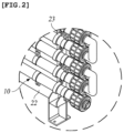
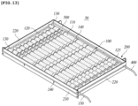
- a plurality of electrolysis cells 10 each cell being the pipe-type electrolysis cell 10 having the structure described above, is connected in series with each other to form a unit module 20 as illustrated in FIG. 1 . Therefore, it is possible to easily provide a module having desired capacity. Furthermore, a plurality of unit modules 20 may be connected in parallel with each other to increase the electrolysis capacity, as illustrated in FIG. 6
- one electrolysis cell 10 and another electrolysis cell 10 are connected via a U-shaped elbow connection member or an arbitrary connection member 21 manufactured through a molding process so that a fluid can flow from one cell to another. Then, the electrolysis cells 10 are fixed to frames 22 using U-shaped saddles 23 or bolts. In addition, upper electrolysis cells 10 and lower electrolysis cells 10 are connected via bus bars 24. In this way, it is possible to manufacture the unit module 20 by connecting multiple electrolysis cells 10. Furthermore, it is possible to assemble and install a large-capacity electrolysis module 30 on site by connecting the unit modules 20 in parallel with each other as shown in FIG. 6 .
- the electrolysis module consisting of the pipe-type electrolysis cells has a higher withstand voltage and a simpler structure than conventional cube-shaped electrolysis modules using a flat plate electrode. Furthermore, since this electrolysis module has an improved velocity profile, it is possible to minimize scale accumulation and facilitate hydrogen emissions.
- Patent Document 1 Korean Patent Application Publication No. 10-2006-0098445 (Electronic Water Treatment System And Method For Controlling The Same)
- the KR 101 412 721 B1 discloses an electrolysis module including an electrolysis unit module in which a plurality of pipe type electrolysis cells are connected in series; a molding case that surrounds the circumference of the electrolysis unit module to protect the electrolysis unit module; a cell guide member that is disposed in the molding case to support the electrolysis unit module; a power cable with one end connected to the electrolysis unit module and the other end extending outward through the molding case; and a resin filling layer that is formed by filling the molding case with a resin material so as to cover the outer side of the electrolysis unit module mounted on the molding case.
- the US 2011/147203A1 discloses a drop-in cell for disinfection of water from bathing pools, particularly whirlpools, with an electrolytic cell which can be flowed through by water and has two contact electrodes, which are positioned in parallel and spaced apart from each other, and preferably at least one bipolar diamond particle electrode, which is arranged between the contact electrodes at a distance from them.
- the electrodes are joined together by spacers located between them to form an elongate, approximately cuboidal electrode pack, which is embedded in a casing of plastic or synthetic resin while leaving an inflow and an outflow free.
- the EP 2 631 334 A1 discloses an electrolysis cell comprising an anode chamber provided with an anode and a cathode chamber provided with a cathode, and which is separated from the anode chamber by a membrane, where the membrane is designed as a hollow ceramic cylinder surrounded by an outer housing, and the hollow ceramic cylinder and the outer housing are respectively mounted at the ends in a closure cap, which has a central bore forming an entry channel to the interior of the hollow ceramic cylinder that forms the membrane, and an annular chamber that runs around the hollow ceramic cylinder.
- the electrolysis cell comprises an anode chamber provided with an anode and a cathode chamber provided with a cathode, and is separated from the anode chamber by a membrane, where the membrane is designed as a hollow ceramic cylinder surrounded by an outer housing, and the hollow ceramic cylinder forming the membrane and the outer housing surrounding the cylinder are respectively mounted at the ends in a closure cap, which has a central bore forming an entry channel to the interior of the hollow ceramic cylinder that forms the membrane and an annular chamber that runs around the hollow ceramic cylinder and is connected to the inter-space between membrane and outer housing, on the media side.
- the GB 2 513 368 A discloses a process apparatus comprising at least one elongate hollow semi-permeable member, at least one anode and at least one cathode.
- the anode and cathode are arranged radially and concentrically with respect to the semi-permeable member.
- the hollow semi-permeable member is a filter element such as a water filter element and it is formed as an anode or cathode. It comprises a plurality of hollow semi-permeable members and associated anodes and cathodes and a housing adapted to communicate liquid from the housing inlet through the plurality of hollow semi-permeable members to an outlet.
- the US 2014/261252A1 A1 discloses a combination air pressure system and a gas generator system adapted for mounting next to an intake manifold of a turbocharged diesel engine.
- the system includes a solution reservoir tank for supplying a fluid mixture to a gas generator.
- the gas generator includes a housing with a plurality of concentric tubular electrodes consisting of both anode and cathode tubular electrodes with a series of interposed bipolar electrodes.
- the CN 2 064 366 U discloses an electrolytic apparatus which generates sodium hypochlorite by electrolyzing salt solution and which is suitable for the treatment of sewage containing bacteria, the treatment of electroplated cyanide containing waste and the sterilization of drinking water.
- the electrolytic apparatus is characterized in that the anode is a cylindrical reticular metallic anode with double-face work; the cathodes are cylindrical metallic cathodes; the anode is positioned between the two cathodes.
- an object of the present invention is to provide an electrolysis module that can reduce the manufacturing cost by reducing the number of parts thereof and simplifying a manufacturing method, and can overcome a space constraint problem by having a size that is about a half of the size of a conventional unit module having the same capacity, while providing advantages of conventional technologies that are proven to be safe.
- Another object of the present invention is to improve uniformity and efficiency of reaction by enabling uniform current distribution throughout pipe-type electrolysis cells arranged in multiple stages.
- the present invention is devised in consideration of the above problems, and is intended to provide an improved pipe-type electrolysis module having a reduced size while maintaining an electrolysis performance, thereby saving installation space and reducing manufacturing cost.
- the inside surface of the inner electrode is plated with a metal having a high electrical conductivity to improve the flow of an electrical current. Therefore, the electrolysis module has improved electrolysis efficiency.
- the electrolysis module is molded with a resin, safety of the electrolysis module can be guaranteed. That is, it is possible to prevent a risk of explosion attributable to a leakage of water and hydrogen gas and to prevent workers or operators from being electrically shocked.
- the coupling of the assembled parts is not loosened by external vibrations. Since the molding treatment is performed with a transparent material, the state of the electrolysis module can be easily inspected or checked, maintenance of the electrolysis module can be conveniently performed, and a maintenance cost is reduced.
- the pipe-type electrolysis cell used in the electrolysis module of the present invention has a structure in which both the inside surface and the outside surface of the bipolar electrode can be used for electrolysis. Therefore, electrolysis efficiency is doubled compared with convention electrolysis cells having the same size. For this reason, it is possible to reduce the size and the manufacturing cost of the electrolysis module, which obviates a problem of space constraint when the electrolysis module is installed in a ship.
- an electrolysis module 50 includes a electrolysis unit module 100, a molding case 200, a cell guide member 300, a power cable 400, and a resin layer 500.
- the electrolysis unit module 100 includes a pipe-type electrolysis cell 110, a connection pipe 120, and an inlet/outlet connection nipple 130.
- the pipe-type electrolysis cell 110 includes a pair of terminal electrodes, a bipolar electrode, an insulation unit, and a spiral block 118.
- the pair of terminal electrodes includes inner electrodes 115a and 115b, outer electrodes 114a and 114b, and connection plates 116 by which first ends of the inner electrodes 115a and 115b are electrically connected to first ends of the outer electrodes 114a and 114b.
- the bipolar electrode includes a pipe-type middle electrode 111 installed between the inner electrodes 115a and 115b and the outer electrodes 114a and 114b.
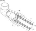
- the middle electrode 111 is a bipolar electrode having opposite polarities at opposite sides thereof. As shown in FIGS. 23A and 23B , each end of the middle electrode 111 is provided with insulating terminal spacers 117. Specifically, each end of the middle electrode 111 is provided with three insulating terminal spacers 117. The three insulating terminal spacers 117 may be arranged at an equal angular interval of 120°C. However, the number and interval of the insulating terminal spacers 117 are not limited thereto. More specifically, the insulating terminal spacers 117 may be provided to protrude outward from an end of the middle electrode 111 in a longitudinal direction and from the outside surface of the middle electrode 111.
- each insulating terminal spacer 117 is provided with a coupling pin 117a to be fitted into a coupling hole 111b provided at an end portion of the middle electrode 111. Due to the insulating terminal spacers 117, the middle electrode 111 can be spaced from the outer electrodes 114a and 114b and from the connection plates 116, by a predetermined distance. Therefore, the middle electrode 111 can be electrically insulated from the outer electrodes and the connection plates.
- the shape of the insulating terminal spacers 117 is not limited to the structure described above.
- the insulating terminal spacers 117 can have any shape if they can space the middle electrode 111 from the outer electrodes 114a and 114b, and the connection plates 116, thereby electrically insulating the middle electrode 111 from the outer electrodes 114a and 114b and the connection plates 116.
- the insulating terminal spacers 117 there is a further requirement that it should not block sea water that is introduced into a channel formed between the electrodes through fluid passing holes formed in the connection plates 116.
- the insulation unit includes an outer insulating spacer 112 installed outside the middle electrode 111, at a middle portion of the middle electrode 111 in a longitudinal direction thereof, and an inner insulating spacer 113 installed inside the middle portion at the middle portion. A further detailed description of the insulation will be given later.
- the outer electrodes 114a and 114b have a pipe shape.
- One outer electrode (114a) of the outer electrodes serves as a cathode and the other outer electrode (114b) serves as an anode.
- the outer insulating spacer 112 is provided between the outer electrode 114a and the outer electrode 114b to electrically insulate the outer electrodes 114a and 114b from each other and spaces the outer electrodes 114a and 114b from the middle electrode 111.
- a middle portion of the inside surface of the outer insulating spacer 112 is provided with protrusions 112a which enable the inside surface of the outer insulating spacer 112 to be spaced from the outside surface of the middle electrode 111 by a predetermined distance.
- the protrusions 112a may be arranged at regular intervals in the circumferential direction of the outer insulating spacer 112 and are in surface contact with the outside surface of the middle electrode 111. Respective ends of the outer insulating spacer 112 are provided with outer electrode connection portions 112b into which end portions of the outer electrodes 114a and 114b are inserted, in which the outer electrode connection portions 112b have an inner diameter larger than an inner diameter of the middle portion of the outer insulating spacer 112. That is, the inside surface of the electrode connection portion 112b and the inside surface of the middle portion of the insulating outer spacer 112 form a step shape. Therefore, the outer electrodes 114a and 114b are supported on and insulated from each other by the outer insulating spacer 112.
- adjacent ends (second ends) of the outer electrodes 114a and 114b are assembled with the outer insulating spacer 112, and the other ends (first ends) are respectively assembled with the connection pipes 120 or the inlet/outlet connection nipples 130.
- first ends of the outer electrodes 114a and 114b are connected to first ends of the inner electrodes 115a and 115b by the connection plates 116.
- the connection plates 116 are made of a metal.
- the first ends of the inner electrodes 115a and 115b and the first ends of the outer electrodes 114a and 114b are connected through a connection method such as welding that does not increase electrical resistance. Therefore, as to the inner electrodes 115a and 115b and the outer electrodes 114a and 114b connected by the connection plate 116, the outer electrode 114a and the inner electrode 115a, connected to each other, have the same polarity (i.e. both serving as a cathode) and the outer electrode 114b and the inner electrode 115b have the same polarity (i.e. both serving as an anode).
- the inner insulating spacer 113 is provided between the inner electrodes 115a and 115b, so that the inner electrodes 115a and 115b are electrically insulated from each other by the inner insulating spacer 113.
- the inner insulating spacer 113 also spaces and electrically insulates the inner electrodes 115a and 115b from the middle electrode 111.
- the inner insulating spacer 113 is installed at a middle portion inside the middle electrode 111 and is provided with a plurality of protrusions 113 on the outside surface thereof.
- the protrusions 113a protrude from the outside surface 113 of the inner insulating spacer 113 and are arranged at regular intervals in the circumferential direction.
- the protrusions 113 are in contact with the inside surface of the middle electrode 111.
- Respective ends of the inner insulating spacer 113 are provided with inner electrode connection portions 113b that have a smaller outer diameter than that of a middle portion of the inner insulating spacer 113 such that the outside surface of the inner electrode connection portion 113b and the outside surface of the middle portion of the inner insulating spacer 113 form a step shape. Therefore, the inner electrode connection portions 113b of the inner insulating spacer 113 can be respectively inserted into the adjacent ends of the inner electrodes 115a and 115b.
- the inner insulating spacer 113 supports the inner electrodes 115a and 115b while electrically insulating the inner electrodes 115a and 115b from each other, and also spaces and electrically insulates the inner electrodes 115a and 115b from the middle electrode 111.
- the outer insulating spacer 112 and the inner insulating spacer 113 have a structure that can meet requirements that the outer electrodes 114a and 114b can be supported in a state of being electrically insulated from each other, the inner electrodes 115a and 115b can be supported in a state of being electrically insulated from each other, and the outer electrodes and the inner electrodes can be spaced and electrically insulated from the middle electrode 111 by a predetermined distance.
- the protrusions 112a of the outer insulating spacer 112 and the protrusions 113a of the inner insulating spacer 113 which are provided to space and electrically insulate the outer electrodes and the inner electrodes from the middle electrode 111, are preferably configured not to impede the flow of sea water which flows along a channel provided between the outer electrode and the middle electrode and a channel provided between the inner electrode and the middle electrode.
- the bipolar electrode i.e. the pipe-type middle electrode 111, 11, which is disposed between and spaced from the outer electrodes 114a and 114b and the inner electrodes 115a and 115b, with respect to the outer electrodes 114a and 114b and the inner electrodes 115a and 115b.
- an electrolytic reaction occurs in a state in which a fluid flows along the outside surface and the inside surface of the middle electrode 111. Since the electrolytic reaction occurs while the fluid is flowing along the outside surface and the inside surface of the middle electrode 111, the pipe-type electrolysis cell of the present invention exhibits electrolysis performance that is twice or more than that of conventional pipe-type electrolysis cells.
- the pipe-type electrolysis cell of the invention can obtain two times higher electrolysis efficiency than the conventional pipe-type electrolysis cell. Since those skilled in the art can easily understand the detailed structure and operation of the pipe-type electrolysis cell, there will be no further description thereof.
- connection plate 116 is provided with a plurality of fluid passing holes 116a that are equal in size and are arranged at regular intervals in a circumferential direction of the connection plate 116 such that the fluid can be introduced into a gap between the inner electrodes 115a and 115b and the outer electrodes 114a and 114b.
- one or more positioning guide pins 116b are formed to protrude from the outside surface of the connection plate 116. The positioning guide pins 116b are configured to enable a combined structure of the electrodes to be precisely and accurately aligned with the spiral block 118 when the combined structure of the electrodes is combined with the spiral block.
- connection plate 116 may be made of a plurality of plates arranged in multiple stages. In this case, the plates are stacked such that the fluid passing holes provided to each plate are misaligned. That is, a fluid path extending through the fluid passing holes of the plates may form a spiral shape. Alternatively, each fluid passing hole 116a may extend in a spiral form in the connection plate 116, thereby guiding the fluid along a spiral flow path.
- the spiral block 118 is connected to the outside surface of the connection plate 116.
- the spiral block 118 is provided with a plurality of spiral guide holes 118a that are arranged at intervals in a circumferential direction of the spiral block 118. Since the fluid spirally flows while passing through the spiral guide holes 118a, velocity distribution of the fluid can be uniformized.
- the spiral block 118 is provided with a positioning hole 118b that is used to position the spiral block 118 such that the guide holes 118a of the spiral block 118 can be precisely and accurately aligned with the fluid passing holes 116a of the connection plate 116 when the spiral block 118 is connected to the connection plate 116.
- connection plate 116 When the positioning guide pin 116b of the connection plate 116 is inserted into the positioning hole 118b, the fluid passing holes 116a are automatically aligned with the guides hole 118a. Therefore, the fluid can flow without flow resistance.
- the spiral block 118 is assembled with the connection pipe 120 or the inlet/outlet connection nipple 130.
- the middle electrode 111 a half of each of the outside surface and the inside surface in terms of the longitudinal direction is coated with an anode material. That is, both of the outside surface and the inside surface of the middle electrode 111 can be used for an electrolytic reaction unlike conventional arts. Therefore, electrolysis capacity is doubled.
- the outer electrode 114a serving as the cathode and the inner electrode 115a serving as the cathode are made of stainless steel or nickel alloys.
- the outer electrode 114a and the inner electrode 115a serving as the cathode are connected to the connection plate 116 through a connection method such as welding that does not increase electric resistance.
- one or more surfaces of the electrodes, which do not participate in an electrolytic reaction while the sea water flows for example, i.e. the inside surface of the inner electrode 115a or the outside surface of the outer electrode 114a, are preferably coated with a metal having a high electric conductivity, which uniformly distributes current intensity over the entire length of the electrode during the electrolytic reaction. For this reason, uniformity and efficiency of the electrolytic reaction can be improved compared with conventional multi-stage electrolytic cells, and heat generated during the electrolytic reaction can be controlled.
- the outer electrode 114b and the inner electrode 115b serving as the anode are made of titanium.
- the inside surface of the outer electrode 114a and the outside surface of the inner electrode 115b are coated with a platinum oxide to form insoluble electrodes.
- these electrodes are plated and welded in the same manner as the electrodes serving as the cathode described above, thereby maintaining the electrical conductivity.
- a plurality of pipe-type electrolysis cells 110 having the structure described above are arranged in series, and adjacent ends thereof are connected to each other by the connection pipe 120 so that a fluid can flow from one cell to another.
- the connection pipe 120 has a U shape.
- the outermost pipe-type electrolysis cells 110 of the electrolysis unit module 100 are connected to power cables 400.
- the outermost electrolysis cells 110 are connected to the inlet/outlet connection nipples 130. That is, outer ends of both of the outermost pipe-type electrolysis cell 110 are connected to the connection pipes 120 or the connection nipples 130. Alternatively, the outer end of one of the outermost pipe-type electrolysis cells 110 may be connected to the connection pipe 120 and the outer end of the other of the outermost pipe-type electrolysis cells 110 may be connected to the connection nipple 130.
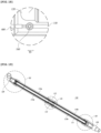
- the connection pipe 120 and the connection nipple 130 are elements through which a fluid can be introduced into the pipe-type electrolysis cell 110 or fluid in the pipe-type electrode cell 110 can be discharged outside.
- connection pipe 120 and the connection nipple 130 are assembled with ends of the spiral blocks 118.
- the connection nipple 130 may extend to the outside of the molding case 200 through a nipple passing hole 230 (see FIGS. 12A and 12B ) formed in the molding case 200.
- an internal fluid channel i.e. fluid passage channel
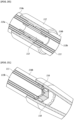
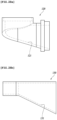
- the connection pipe 120 and the connection nipple 130 have bottom surfaces 121 and 131 that are sloped upward toward the outer ends thereof as shown in FIGS. 28A and 28B .
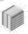
- the electrolysis unit module 100 is configured such that a plurality of pipe-type electrolysis cells 110 is arranged in series and assembled as shown in FIG. 12 , in which adjacent pipe-type electrolysis cells 110 are electrically connected to each other by a ring-shaped connection terminal 140 in the assembled state.
- terminals 150 are connected to connectors 140 connected to the outermost pipe-type electrolysis cells 110, and the power cables 400 are connected to the terminal 150 by coupling members 160 (see FIG. 18 ) such as bolts.
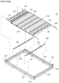
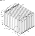
- the molding case 200 has a rectangular frame shape.
- the assembled electrolysis unit module 100 is molded in a state of being disposed inside the molding case 200.
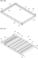
- the molding case 200 consists of a pair of long bars 210 and a pair of short bars 220 that are connected to respective ends of the long bars 210. Inner surfaces of the long bars 210 are provided with guide member assembling holes 240 into which ends of the cell guide members 300 are inserted.
- the short bars 220 are provided with cable passing holes 250 through which the power cables 400 pass and the nipple passing holes 230 through which the inlet/outlet connection nipples 130 pass.
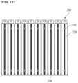
- each cell guide member 300 there are multiple cell guide members 300. Respective ends of each cell guide member 300 are inserted into the guide member assembling holes 240 formed in the long bars 210 such that the cell guide members 300 are disposed inside the molding case 200, thereby supporting the assembled electrolysis unit module 100. To this end, the cell guide members 300 are installed to extend across the molding case 200.
- the cell guide members 300 are made of a flexible insulating material or have a flexible structure.
- the cell guide member 300 has a structure in which arc-shaped concave portions 310 are arranged in a row, thereby conforming to the outer surfaces of the pipe-type electrolysis cells 110 connected in series with each other. Thus, the cell guide member 300 can be in tight contact with and can support the outer surfaces of the pipe-type electrolysis cells 110.
- a molding case 200' may be configured such that a resin filling portion (refer to reference characteristics D1 and D2) is bent to increase bonding force to a resin or an inner surface of the molding case 200' is imparted with surface roughness.
- a resin filling portion (refer to reference characteristics D1 and D2) is bent to increase bonding force to a resin or an inner surface of the molding case 200' is imparted with surface roughness.
- the molding case 200 is filled with a resin and the resin is cured. Next, the molding case 200 is removed (see FIG. 12C ).
- the filled and cured resin may function as the molding case.
- the assembled electrolysis unit module 100 is placed on the cell guide member 300.
- the electrolysis unit module 100 is provided inside the molding case 200.
- the power cable 400 is connected to the electrolysis unit module 100, and then a resin is introduced into a space in the molding case 200 and supplied to surround the entire surface of the electrolysis unit module 100, thereby forming a resin layer 400.
- the resin layer 400 may be preferably formed of epoxy resin.
- the resin layer 400 may be preferably made of a fire retardant resin.
- the state of the molded electrolysis unit module 100 can be checked from outside.
- the electrolysis capacity of the molded electrolysis module 50 can be changed and adjusted by compactly connecting the electrolysis cells.
- the molded electrolysis module 50 since the molded electrolysis module 50 is in a safe state in which water and hydrogen leakage is prevented and workers are protected from electric shock, it is unnecessary to encase an electrolysis module as is required in conventional arts. Therefore, it is not necessary to use a water sensor for sensing water leakage, nor a hydrogen sensor for sensing hydrogen leakage. For this reason, the manufacturing cost can be reduced.
- the state of the electrolysis module can be easily checked and inspected, and thus maintenance of the electrolysis module becomes easy.
- the pipe-type electrolysis cell 110 is structured such that the pipe-type bipolar electrode (i.e. middle electrode) is arranged between the terminal electrodes consisting of the outer electrode and the inner electrode, thereby enabling the electrolytic reaction to occur on both the inside surface and the outside surface of the bipolar electrode.
- the electrolysis module can obtain an electrolysis performance equal to that of a conventional electrolysis module even while being only half the size.
- the amount of electrode material is reduced to about 65 %, and the amount of epoxy molding material and the amount of frames are also reduced by about 50 %.
- the electrolysis module of the invention is considerably more cost effective.
- the electrolysis module of the invention can be installed in old ships as well as new ships because it requires a reduced installation space.
- Electrolysis module 100 Electrolysis unit module 110: Pipe-type electrolysis cell 120: Connection pipe 130: Connection nipple 200: Molding case 300: Cell guide member 400: Power cable 500: Resin layer
Landscapes
- Chemical & Material Sciences (AREA)
- Organic Chemistry (AREA)
- Engineering & Computer Science (AREA)
- Chemical Kinetics & Catalysis (AREA)
- Electrochemistry (AREA)
- Life Sciences & Earth Sciences (AREA)
- General Chemical & Material Sciences (AREA)
- Hydrology & Water Resources (AREA)
- Environmental & Geological Engineering (AREA)
- Water Supply & Treatment (AREA)
- Metallurgy (AREA)
- Materials Engineering (AREA)
- Inorganic Chemistry (AREA)
- Electrolytic Production Of Non-Metals, Compounds, Apparatuses Therefor (AREA)
- Water Treatment By Electricity Or Magnetism (AREA)
Claims (8)
- Module d'électrolyse (50) comprenant :un module d'unité d'électrolyse (100) incluant une pluralité de cellules d'électrolyse de type tube (110) connectées en série les unes avec les autres ;un boîtier de moulage (200) entourant et protégeant le module d'unité d'électrolyse (100) ;un élément de guidage de cellule (300) s'étendant de part et d'autre du boîtier de moulage (200) et soutenant le module d'unité d'électrolyse (100) ;un câble d'alimentation (400) ayant une première extrémité connectée au module d'unité d'électrolyse (100) et une deuxième extrémité s'étendant vers une zone extérieure à travers le boîtier de moulage (200) ; etune couche de résine (500) remplie dans le boîtier de moulage (200) couvrant une surface externe du module d'unité d'électrolyse (100) disposé dans le boîtier de moulage (200),dans lequel la cellule d'électrolyse de type tube (110) comprend : une paire d'électrodes terminales (114a, 114b, 115a, 115b) incluant des électrodes externes de type tube (114a, 114b) et des électrodes internes de type tube (115a, 115b) qui sont connectées l'une à l'autre à des premières extrémités de celles-ci et séparées l'une de l'autre à des deuxièmes extrémités de celles-ci ; et une électrode centrale bipolaire de type tube (111) installée entre les électrodes terminales (114a, 114b, 115a, 115b) et isolée électriquement des électrodes terminales (114a, 114b, 115a, 115b),dans lequel la cellule d'électrolyse de type tube (110) comprend en outre : une unité d'isolation comprenant un dispositif d'espacement d'isolation externe (112) installé à l'extérieur de l'électrode centrale bipolaire de type tube (111), au niveau d'une partie centrale de l'électrode centrale bipolaire de type tube (111) dans une direction longitudinale de celle-ci, et un dispositif d'espacement d'isolation interne (113) installé à l'intérieur de l'électrode centrale bipolaire de type tube (111) au niveau de la partie centrale,dans lequel une partie centrale de la surface intérieure du dispositif d'espacement d'isolation externe (112) est pourvue de protubérances (112a),dans lequel les protubérances (112a) sont disposées à intervalles réguliers dans la direction circonférentielle du dispositif d'espacement d'isolation externe (112) et sont en contact de surface avec la surface extérieure de l'électrode centrale bipolaire de type tube (111),dans lequel le dispositif d'espacement d'isolation interne (113) est pourvu d'une pluralité de protubérances (113a) sur la surface extérieure de celui-ci,dans lequel les protubérances (113a) font saillie à partir de la surface extérieure (113c) du dispositif d'espacement d'isolation interne (113), sont disposées à intervalles réguliers dans la direction circonférentielle et sont en contact avec la surface intérieure de l'électrode centrale bipolaire de type tube (111),dans lequel le dispositif d'espacement d'isolation externe (112) est disposé entre les électrodes externes (114a, 114b) pour les isoler l'une de l'autre et les espacer de l'électrode centrale bipolaire de type tube (111),dans lequel, pour soutenir et isoler les électrodes externes (114a, 114b) l'une de l'autre, les extrémités du dispositif d'espacement d'isolation externe (112) ont des parties de connexion d'électrode externe (112b) avec une forme de marche dans laquelle les parties d'extrémité des électrodes externes (114a, 114b) sont insérées,dans lequel pour espacer les électrodes externes (114a, 114b) de l'électrode centrale bipolaire de type tube (111), les protubérances (112a) sont configurées pour espacer la surface intérieure du dispositif d'espacement d'isolation externe (112) de l'électrode centrale bipolaire de type tube (111) d'une distance prédéterminée,dans lequel le dispositif d'espacement d'isolation interne (113) est disposé entre les électrodes internes (115a, 115b) pour les isoler l'une de l'autre et pour les espacer de l'électrode centrale bipolaire de type tube (111),dans lequel, pour soutenir et isoler les électrodes internes (115a, 115b) l'une de l'autre, les extrémités du dispositif d'espacement d'isolation interne (113) ont des parties de connexion d'électrode interne (113b) avec une forme de marche qui sont insérées dans les extrémités adjacentes des électrodes internes (115a, 115b),dans lequel, pour espacer les électrodes internes (115a, 115b) de l'électrode centrale bipolaire de type tube (111), les protubérances (113a) sont configurées pour espacer la surface extérieure du dispositif d'espacement d'isolation interne (113) de l'électrode centrale bipolaire de type tube (111) d'une distance prédéterminée.
- Module d'électrolyse (50) selon la revendication 1, dans lequel la cellule d'électrolyse de type tube (110) comprend en outre :
un bloc hélicoïdal (118) combiné avec les extrémités connectées des électrodes terminales (114a, 114b, 115a, 115b) et pourvu d'un trou de guidage hélicoïdal (118a) à travers lequel un fluide est apte à passer. - Module d'électrolyse (50) selon la revendication 2, dans lequel la cellule d'électrolyse de type tube (110) inclut une plaque de connexion (116) connectant et soutenant les extrémités de l'électrode interne (115a, 115b) et de l'électrode externe (114a, 114b), la plaque de connexion (116) étant pourvue d'un trou de passage de fluide (116a) communiquant avec un canal formé entre l'électrode interne (115a, 115b) et l'électrode externe (114a, 114b) et guidant un fluide vers le canal.
- Module d'électrolyse (50) selon la revendication 3, comprenant en outre un dispositif d'espacement d'isolation terminale (117) installé à chaque extrémité de l'électrode bipolaire (111) et espaçant et isolant électriquement l'électrode bipolaire (111) de la plaque de connexion (116), de l'électrode interne (115a, 115b) et de l'électrode externe (114a, 114b).
- Module d'électrolyse (50) selon la revendication 1, dans lequel au moins l'une quelconque d'une surface externe de l'électrode externe (114a, 114b) et d'une surface interne de l'électrode interne (115a, 115b), qui sont des surfaces qui ne sont pas impliquées dans une réaction électrolytique, est revêtue d'un métal ayant une conductivité électrique élevée.
- Module d'électrolyse (50) selon la revendication 3, dans lequel la plaque de connexion (116) ayant le trou de passage de fluide (116a) est connectée à l'électrode externe (114a, 114b) par soudage.
- Module d'électrolyse (50) selon la revendication 3, dans lequel les trous de passage de fluide (116a) formés dans la plaque de connexion (116) sont des trous traversants alignés avec les trous de guidage hélicoïdaux (118a) formés dans le bloc hélicoïdal (118).
- Module d'électrolyse (50) selon la revendication 3, comprenant une pluralité de modules d'unité d'électrolyse (100), dans lequel les modules d'unité d'électrolyse (100) sont connectés en parallèle les uns avec les autres pour augmenter une capacité.
Applications Claiming Priority (2)
| Application Number | Priority Date | Filing Date | Title |
|---|---|---|---|
| KR1020140187429A KR101686138B1 (ko) | 2014-12-23 | 2014-12-23 | 전해모듈 |
| PCT/KR2015/011465 WO2016104934A1 (fr) | 2014-12-23 | 2015-10-28 | Module d'électrolyse |
Publications (3)
| Publication Number | Publication Date |
|---|---|
| EP3239105A1 EP3239105A1 (fr) | 2017-11-01 |
| EP3239105A4 EP3239105A4 (fr) | 2018-08-01 |
| EP3239105B1 true EP3239105B1 (fr) | 2024-08-28 |
Family
ID=56150916
Family Applications (1)
| Application Number | Title | Priority Date | Filing Date |
|---|---|---|---|
| EP15873462.4A Active EP3239105B1 (fr) | 2014-12-23 | 2015-10-28 | Module d'électrolyse |
Country Status (6)
| Country | Link |
|---|---|
| US (1) | US10494275B2 (fr) |
| EP (1) | EP3239105B1 (fr) |
| JP (1) | JP6538171B2 (fr) |
| KR (1) | KR101686138B1 (fr) |
| CN (1) | CN107109670B (fr) |
| WO (1) | WO2016104934A1 (fr) |
Families Citing this family (4)
| Publication number | Priority date | Publication date | Assignee | Title |
|---|---|---|---|---|
| SG10202111432YA (en) * | 2017-04-14 | 2021-12-30 | Evoqua Water Tech Llc | Internal electrical connections for concentric tubular electrochemical cells |
| EP3823112A1 (fr) * | 2019-11-18 | 2021-05-19 | Groon Co., Ltd. | Appareil de génération d'images apte à amplifier la capacité variable à plusieurs niveaux |
| US20240166538A1 (en) * | 2022-11-21 | 2024-05-23 | Oxbyel Technologies, Inc. | Water treatment process incorporating a split cell electrochemical reactor |
| TWI877794B (zh) * | 2023-09-18 | 2025-03-21 | 育勝環境科技有限公司 | 電解槽結構 |
Citations (2)
| Publication number | Priority date | Publication date | Assignee | Title |
|---|---|---|---|---|
| CN2064366U (zh) * | 1989-12-05 | 1990-10-24 | 航空航天部航空工业规划设计研究院 | 双极阴极换向除垢次氯酸钠发生器 |
| US20140261252A1 (en) * | 2013-03-15 | 2014-09-18 | CFT Global, LLC. | Pressure induced cylindrical gas generator system for the electrolysis of ammonium hydroxide |
Family Cites Families (16)
| Publication number | Priority date | Publication date | Assignee | Title |
|---|---|---|---|---|
| JPS59154397U (ja) * | 1983-03-31 | 1984-10-16 | 株式会社 公害防止綜合研究所 | 電解槽用陽極体 |
| AU1574588A (en) * | 1987-06-09 | 1989-01-04 | Cleanup And Recovery Corporation | System for electrolytic treatment of liquid |
| JP3509999B2 (ja) * | 1995-05-22 | 2004-03-22 | ホシザキ電機株式会社 | 電解水生成装置 |
| KR100718723B1 (ko) | 2005-03-03 | 2007-05-15 | 주식회사 성창엔지니어링 | 전자장 수처리 장치 및 그 제어방법 |
| JP5082256B2 (ja) * | 2006-02-23 | 2012-11-28 | パナソニック株式会社 | 密閉型蓄電池 |
| KR20100011851A (ko) * | 2008-07-25 | 2010-02-03 | 한국원자력연구원 | 전해셀 |
| AT509286B1 (de) * | 2009-12-16 | 2016-10-15 | Pro Aqua Diamantelektroden Produktion Gmbh Und Co Kg | Tauchzelle zur elektrolytischen desinfektion von wasser |
| CN102762773B (zh) | 2010-03-15 | 2016-01-20 | 唯一科技股份公司 | 次氯酸钠制造用电解槽 |
| EP2546389A1 (fr) * | 2011-07-14 | 2013-01-16 | United Initiators GmbH & Co. KG | Procédé de fabrication de peroxodisulfate alcalin ou d'ammonium dans une pièce d'électrolyse non divisée |
| CN103058425B (zh) * | 2011-10-21 | 2015-07-29 | 通用电气公司 | 脱盐系统和方法 |
| EP2617874B1 (fr) * | 2012-01-18 | 2015-06-03 | H-TEC Systems GmbH | Electrolyseur |
| EP2631334A1 (fr) * | 2012-02-24 | 2013-08-28 | Caliopa AG | Cellule électrolytique, notamment pour l'utilisation dans une installation destinée à la production d'une solution de chlorure de sodium activée de manière électrochimique, ainsi qu'installation dotée d'un certain nombre de telles cellules électrolytiques |
| KR101389937B1 (ko) * | 2012-03-29 | 2014-04-30 | (주) 테크윈 | 파이프형 전해셀 |
| GB2513368B (en) * | 2013-04-25 | 2016-01-27 | Radical Filtration Ltd | Process apparatus |
| KR101466371B1 (ko) | 2013-04-30 | 2014-11-27 | 주식회사 욱영전해씨스템 | 고농도 차아염소산나트륨 생산용 나트륨 해수전해장치 |
| KR101412721B1 (ko) * | 2013-05-23 | 2014-06-30 | (주) 테크윈 | 전해모듈 |
-
2014
- 2014-12-23 KR KR1020140187429A patent/KR101686138B1/ko active Active
-
2015
- 2015-10-28 CN CN201580069422.7A patent/CN107109670B/zh active Active
- 2015-10-28 WO PCT/KR2015/011465 patent/WO2016104934A1/fr not_active Ceased
- 2015-10-28 EP EP15873462.4A patent/EP3239105B1/fr active Active
- 2015-10-28 JP JP2017533871A patent/JP6538171B2/ja active Active
-
2017
- 2017-06-15 US US15/624,158 patent/US10494275B2/en active Active
Patent Citations (2)
| Publication number | Priority date | Publication date | Assignee | Title |
|---|---|---|---|---|
| CN2064366U (zh) * | 1989-12-05 | 1990-10-24 | 航空航天部航空工业规划设计研究院 | 双极阴极换向除垢次氯酸钠发生器 |
| US20140261252A1 (en) * | 2013-03-15 | 2014-09-18 | CFT Global, LLC. | Pressure induced cylindrical gas generator system for the electrolysis of ammonium hydroxide |
Also Published As
| Publication number | Publication date |
|---|---|
| KR20160076859A (ko) | 2016-07-01 |
| EP3239105A4 (fr) | 2018-08-01 |
| CN107109670B (zh) | 2019-05-21 |
| WO2016104934A1 (fr) | 2016-06-30 |
| CN107109670A (zh) | 2017-08-29 |
| US10494275B2 (en) | 2019-12-03 |
| KR101686138B1 (ko) | 2016-12-28 |
| US20170283284A1 (en) | 2017-10-05 |
| JP6538171B2 (ja) | 2019-07-03 |
| JP2018508339A (ja) | 2018-03-29 |
| EP3239105A1 (fr) | 2017-11-01 |
Similar Documents
| Publication | Publication Date | Title |
|---|---|---|
| CN103917694B (zh) | 管型电解装置 | |
| EP3239105B1 (fr) | Module d'électrolyse | |
| EP2705173B1 (fr) | Générateur de gaz hydrogène | |
| US10550485B2 (en) | Pipe-type electrolysis cell | |
| ES2209875T3 (es) | Estructura electrodica. | |
| CN111032919B (zh) | 电解池及电解池用电极板 | |
| WO2011115370A2 (fr) | Electrolyseur destiné à produire de l'hypochlorite de sodium | |
| JP2009228041A (ja) | 電解装置および電解方法 | |
| KR100497996B1 (ko) | 다수의 전해관을 구비한 전해조 | |
| US20020056635A1 (en) | Electrolytic cell for hypochlorite generation | |
| KR101329046B1 (ko) | 차아염소산 나트륨 제조용 튜브형 전해조 | |
| KR101412721B1 (ko) | 전해모듈 | |
| KR200475903Y1 (ko) | 튜블라 타입 전해 장치 | |
| HK1241423B (zh) | 电解模块 | |
| HK1241423A1 (en) | Electrolysis module | |
| KR101339051B1 (ko) | 튜브형 전해조의 보호 및 지지장치 | |
| HK1241422A1 (en) | Pipe-type electrolysis cell | |
| CA3209715A1 (fr) | Reacteur electrolytique et procedes pour le traitement electrolytique de fluides | |
| AU723896B2 (en) | Electrochemical cell | |
| KR20170064792A (ko) | 물의 전기분해를 이용한 수소 및 산소 발생 시스템 | |
| HK1241422B (zh) | 管式电解槽 | |
| UA107435U (uk) | Проточна електрохімічна комірка для отримання розчину натрію гіпохлориту | |
| JP2007054813A (ja) | 銅イオン供給装置 | |
| WO2014204332A1 (fr) | Cellule modulaire électrochimique pour le traitement de solutions d'électrolytes | |
| HK1193850B (zh) | 氢气发生器 |
Legal Events
| Date | Code | Title | Description |
|---|---|---|---|
| STAA | Information on the status of an ep patent application or granted ep patent |
Free format text: STATUS: THE INTERNATIONAL PUBLICATION HAS BEEN MADE |
|
| PUAI | Public reference made under article 153(3) epc to a published international application that has entered the european phase |
Free format text: ORIGINAL CODE: 0009012 |
|
| STAA | Information on the status of an ep patent application or granted ep patent |
Free format text: STATUS: REQUEST FOR EXAMINATION WAS MADE |
|
| 17P | Request for examination filed |
Effective date: 20170627 |
|
| AK | Designated contracting states |
Kind code of ref document: A1 Designated state(s): AL AT BE BG CH CY CZ DE DK EE ES FI FR GB GR HR HU IE IS IT LI LT LU LV MC MK MT NL NO PL PT RO RS SE SI SK SM TR |
|
| AX | Request for extension of the european patent |
Extension state: BA ME |
|
| DAV | Request for validation of the european patent (deleted) | ||
| DAX | Request for extension of the european patent (deleted) | ||
| A4 | Supplementary search report drawn up and despatched |
Effective date: 20180628 |
|
| RIC1 | Information provided on ipc code assigned before grant |
Ipc: C02F 1/461 20060101AFI20180622BHEP |
|
| STAA | Information on the status of an ep patent application or granted ep patent |
Free format text: STATUS: EXAMINATION IS IN PROGRESS |
|
| 17Q | First examination report despatched |
Effective date: 20200921 |
|
| GRAP | Despatch of communication of intention to grant a patent |
Free format text: ORIGINAL CODE: EPIDOSNIGR1 |
|
| STAA | Information on the status of an ep patent application or granted ep patent |
Free format text: STATUS: GRANT OF PATENT IS INTENDED |
|
| INTG | Intention to grant announced |
Effective date: 20240419 |
|
| GRAS | Grant fee paid |
Free format text: ORIGINAL CODE: EPIDOSNIGR3 |
|
| GRAA | (expected) grant |
Free format text: ORIGINAL CODE: 0009210 |
|
| STAA | Information on the status of an ep patent application or granted ep patent |
Free format text: STATUS: THE PATENT HAS BEEN GRANTED |
|
| AK | Designated contracting states |
Kind code of ref document: B1 Designated state(s): AL AT BE BG CH CY CZ DE DK EE ES FI FR GB GR HR HU IE IS IT LI LT LU LV MC MK MT NL NO PL PT RO RS SE SI SK SM TR |
|
| REG | Reference to a national code |
Ref country code: GB Ref legal event code: FG4D |
|
| REG | Reference to a national code |
Ref country code: CH Ref legal event code: EP |
|
| REG | Reference to a national code |
Ref country code: DE Ref legal event code: R096 Ref document number: 602015089719 Country of ref document: DE |
|
| P01 | Opt-out of the competence of the unified patent court (upc) registered |
Free format text: CASE NUMBER: APP_47632/2024 Effective date: 20240819 |
|
| REG | Reference to a national code |
Ref country code: IE Ref legal event code: FG4D |
|
| REG | Reference to a national code |
Ref country code: NL Ref legal event code: FP |
|
| REG | Reference to a national code |
Ref country code: LT Ref legal event code: MG9D |
|
| REG | Reference to a national code |
Ref country code: GR Ref legal event code: EP Ref document number: 20240402535 Country of ref document: GR Effective date: 20241209 |
|
| PG25 | Lapsed in a contracting state [announced via postgrant information from national office to epo] |
Ref country code: NO Free format text: LAPSE BECAUSE OF FAILURE TO SUBMIT A TRANSLATION OF THE DESCRIPTION OR TO PAY THE FEE WITHIN THE PRESCRIBED TIME-LIMIT Effective date: 20241128 |
|
| REG | Reference to a national code |
Ref country code: AT Ref legal event code: MK05 Ref document number: 1717818 Country of ref document: AT Kind code of ref document: T Effective date: 20240828 |
|
| PG25 | Lapsed in a contracting state [announced via postgrant information from national office to epo] |
Ref country code: FI Free format text: LAPSE BECAUSE OF FAILURE TO SUBMIT A TRANSLATION OF THE DESCRIPTION OR TO PAY THE FEE WITHIN THE PRESCRIBED TIME-LIMIT Effective date: 20240828 Ref country code: PT Free format text: LAPSE BECAUSE OF FAILURE TO SUBMIT A TRANSLATION OF THE DESCRIPTION OR TO PAY THE FEE WITHIN THE PRESCRIBED TIME-LIMIT Effective date: 20241230 Ref country code: PL Free format text: LAPSE BECAUSE OF FAILURE TO SUBMIT A TRANSLATION OF THE DESCRIPTION OR TO PAY THE FEE WITHIN THE PRESCRIBED TIME-LIMIT Effective date: 20240828 |
|
| PG25 | Lapsed in a contracting state [announced via postgrant information from national office to epo] |
Ref country code: BG Free format text: LAPSE BECAUSE OF FAILURE TO SUBMIT A TRANSLATION OF THE DESCRIPTION OR TO PAY THE FEE WITHIN THE PRESCRIBED TIME-LIMIT Effective date: 20240828 |
|
| PG25 | Lapsed in a contracting state [announced via postgrant information from national office to epo] |
Ref country code: LV Free format text: LAPSE BECAUSE OF FAILURE TO SUBMIT A TRANSLATION OF THE DESCRIPTION OR TO PAY THE FEE WITHIN THE PRESCRIBED TIME-LIMIT Effective date: 20240828 |
|
| PG25 | Lapsed in a contracting state [announced via postgrant information from national office to epo] |
Ref country code: IS Free format text: LAPSE BECAUSE OF FAILURE TO SUBMIT A TRANSLATION OF THE DESCRIPTION OR TO PAY THE FEE WITHIN THE PRESCRIBED TIME-LIMIT Effective date: 20241228 Ref country code: AT Free format text: LAPSE BECAUSE OF FAILURE TO SUBMIT A TRANSLATION OF THE DESCRIPTION OR TO PAY THE FEE WITHIN THE PRESCRIBED TIME-LIMIT Effective date: 20240828 |
|
| PG25 | Lapsed in a contracting state [announced via postgrant information from national office to epo] |
Ref country code: HR Free format text: LAPSE BECAUSE OF FAILURE TO SUBMIT A TRANSLATION OF THE DESCRIPTION OR TO PAY THE FEE WITHIN THE PRESCRIBED TIME-LIMIT Effective date: 20240828 |
|
| PG25 | Lapsed in a contracting state [announced via postgrant information from national office to epo] |
Ref country code: RS Free format text: LAPSE BECAUSE OF FAILURE TO SUBMIT A TRANSLATION OF THE DESCRIPTION OR TO PAY THE FEE WITHIN THE PRESCRIBED TIME-LIMIT Effective date: 20241128 Ref country code: ES Free format text: LAPSE BECAUSE OF FAILURE TO SUBMIT A TRANSLATION OF THE DESCRIPTION OR TO PAY THE FEE WITHIN THE PRESCRIBED TIME-LIMIT Effective date: 20240828 |
|
| PG25 | Lapsed in a contracting state [announced via postgrant information from national office to epo] |
Ref country code: RS Free format text: LAPSE BECAUSE OF FAILURE TO SUBMIT A TRANSLATION OF THE DESCRIPTION OR TO PAY THE FEE WITHIN THE PRESCRIBED TIME-LIMIT Effective date: 20241128 Ref country code: PT Free format text: LAPSE BECAUSE OF FAILURE TO SUBMIT A TRANSLATION OF THE DESCRIPTION OR TO PAY THE FEE WITHIN THE PRESCRIBED TIME-LIMIT Effective date: 20241230 Ref country code: PL Free format text: LAPSE BECAUSE OF FAILURE TO SUBMIT A TRANSLATION OF THE DESCRIPTION OR TO PAY THE FEE WITHIN THE PRESCRIBED TIME-LIMIT Effective date: 20240828 Ref country code: NO Free format text: LAPSE BECAUSE OF FAILURE TO SUBMIT A TRANSLATION OF THE DESCRIPTION OR TO PAY THE FEE WITHIN THE PRESCRIBED TIME-LIMIT Effective date: 20241128 Ref country code: LV Free format text: LAPSE BECAUSE OF FAILURE TO SUBMIT A TRANSLATION OF THE DESCRIPTION OR TO PAY THE FEE WITHIN THE PRESCRIBED TIME-LIMIT Effective date: 20240828 Ref country code: IS Free format text: LAPSE BECAUSE OF FAILURE TO SUBMIT A TRANSLATION OF THE DESCRIPTION OR TO PAY THE FEE WITHIN THE PRESCRIBED TIME-LIMIT Effective date: 20241228 Ref country code: HR Free format text: LAPSE BECAUSE OF FAILURE TO SUBMIT A TRANSLATION OF THE DESCRIPTION OR TO PAY THE FEE WITHIN THE PRESCRIBED TIME-LIMIT Effective date: 20240828 Ref country code: FI Free format text: LAPSE BECAUSE OF FAILURE TO SUBMIT A TRANSLATION OF THE DESCRIPTION OR TO PAY THE FEE WITHIN THE PRESCRIBED TIME-LIMIT Effective date: 20240828 Ref country code: ES Free format text: LAPSE BECAUSE OF FAILURE TO SUBMIT A TRANSLATION OF THE DESCRIPTION OR TO PAY THE FEE WITHIN THE PRESCRIBED TIME-LIMIT Effective date: 20240828 Ref country code: BG Free format text: LAPSE BECAUSE OF FAILURE TO SUBMIT A TRANSLATION OF THE DESCRIPTION OR TO PAY THE FEE WITHIN THE PRESCRIBED TIME-LIMIT Effective date: 20240828 Ref country code: AT Free format text: LAPSE BECAUSE OF FAILURE TO SUBMIT A TRANSLATION OF THE DESCRIPTION OR TO PAY THE FEE WITHIN THE PRESCRIBED TIME-LIMIT Effective date: 20240828 |
|
| PG25 | Lapsed in a contracting state [announced via postgrant information from national office to epo] |
Ref country code: DK Free format text: LAPSE BECAUSE OF FAILURE TO SUBMIT A TRANSLATION OF THE DESCRIPTION OR TO PAY THE FEE WITHIN THE PRESCRIBED TIME-LIMIT Effective date: 20240828 Ref country code: RO Free format text: LAPSE BECAUSE OF FAILURE TO SUBMIT A TRANSLATION OF THE DESCRIPTION OR TO PAY THE FEE WITHIN THE PRESCRIBED TIME-LIMIT Effective date: 20240828 Ref country code: SM Free format text: LAPSE BECAUSE OF FAILURE TO SUBMIT A TRANSLATION OF THE DESCRIPTION OR TO PAY THE FEE WITHIN THE PRESCRIBED TIME-LIMIT Effective date: 20240828 |
|
| PG25 | Lapsed in a contracting state [announced via postgrant information from national office to epo] |
Ref country code: EE Free format text: LAPSE BECAUSE OF FAILURE TO SUBMIT A TRANSLATION OF THE DESCRIPTION OR TO PAY THE FEE WITHIN THE PRESCRIBED TIME-LIMIT Effective date: 20240828 |
|
| PG25 | Lapsed in a contracting state [announced via postgrant information from national office to epo] |
Ref country code: CZ Free format text: LAPSE BECAUSE OF FAILURE TO SUBMIT A TRANSLATION OF THE DESCRIPTION OR TO PAY THE FEE WITHIN THE PRESCRIBED TIME-LIMIT Effective date: 20240828 |
|
| PG25 | Lapsed in a contracting state [announced via postgrant information from national office to epo] |
Ref country code: SK Free format text: LAPSE BECAUSE OF FAILURE TO SUBMIT A TRANSLATION OF THE DESCRIPTION OR TO PAY THE FEE WITHIN THE PRESCRIBED TIME-LIMIT Effective date: 20240828 Ref country code: IT Free format text: LAPSE BECAUSE OF FAILURE TO SUBMIT A TRANSLATION OF THE DESCRIPTION OR TO PAY THE FEE WITHIN THE PRESCRIBED TIME-LIMIT Effective date: 20240828 |
|
| REG | Reference to a national code |
Ref country code: DE Ref legal event code: R119 Ref document number: 602015089719 Country of ref document: DE |
|
| REG | Reference to a national code |
Ref country code: CH Ref legal event code: PL |
|
| PLBE | No opposition filed within time limit |
Free format text: ORIGINAL CODE: 0009261 |
|
| STAA | Information on the status of an ep patent application or granted ep patent |
Free format text: STATUS: NO OPPOSITION FILED WITHIN TIME LIMIT |
|
| PG25 | Lapsed in a contracting state [announced via postgrant information from national office to epo] |
Ref country code: MC Free format text: LAPSE BECAUSE OF FAILURE TO SUBMIT A TRANSLATION OF THE DESCRIPTION OR TO PAY THE FEE WITHIN THE PRESCRIBED TIME-LIMIT Effective date: 20240828 |
|
| PG25 | Lapsed in a contracting state [announced via postgrant information from national office to epo] |
Ref country code: DE Free format text: LAPSE BECAUSE OF NON-PAYMENT OF DUE FEES Effective date: 20250501 |
|
| PG25 | Lapsed in a contracting state [announced via postgrant information from national office to epo] |
Ref country code: BE Free format text: LAPSE BECAUSE OF NON-PAYMENT OF DUE FEES Effective date: 20241031 Ref country code: LU Free format text: LAPSE BECAUSE OF NON-PAYMENT OF DUE FEES Effective date: 20241028 |
|
| PG25 | Lapsed in a contracting state [announced via postgrant information from national office to epo] |
Ref country code: CH Free format text: LAPSE BECAUSE OF NON-PAYMENT OF DUE FEES Effective date: 20241031 |
|
| 26N | No opposition filed |
Effective date: 20250530 |
|
| REG | Reference to a national code |
Ref country code: BE Ref legal event code: MM Effective date: 20241031 |
|
| PG25 | Lapsed in a contracting state [announced via postgrant information from national office to epo] |
Ref country code: SE Free format text: LAPSE BECAUSE OF FAILURE TO SUBMIT A TRANSLATION OF THE DESCRIPTION OR TO PAY THE FEE WITHIN THE PRESCRIBED TIME-LIMIT Effective date: 20240828 |
|
| PG25 | Lapsed in a contracting state [announced via postgrant information from national office to epo] |
Ref country code: IE Free format text: LAPSE BECAUSE OF NON-PAYMENT OF DUE FEES Effective date: 20241028 |
|
| PGFP | Annual fee paid to national office [announced via postgrant information from national office to epo] |
Ref country code: NL Payment date: 20251023 Year of fee payment: 11 |
|
| PGFP | Annual fee paid to national office [announced via postgrant information from national office to epo] |
Ref country code: GB Payment date: 20251024 Year of fee payment: 11 |
|
| PGFP | Annual fee paid to national office [announced via postgrant information from national office to epo] |
Ref country code: FR Payment date: 20251024 Year of fee payment: 11 |
|
| PGFP | Annual fee paid to national office [announced via postgrant information from national office to epo] |
Ref country code: GR Payment date: 20251021 Year of fee payment: 11 |
|
| PG25 | Lapsed in a contracting state [announced via postgrant information from national office to epo] |
Ref country code: HU Free format text: LAPSE BECAUSE OF FAILURE TO SUBMIT A TRANSLATION OF THE DESCRIPTION OR TO PAY THE FEE WITHIN THE PRESCRIBED TIME-LIMIT; INVALID AB INITIO Effective date: 20151028 |
|
| PG25 | Lapsed in a contracting state [announced via postgrant information from national office to epo] |
Ref country code: CY Free format text: LAPSE BECAUSE OF FAILURE TO SUBMIT A TRANSLATION OF THE DESCRIPTION OR TO PAY THE FEE WITHIN THE PRESCRIBED TIME-LIMIT; INVALID AB INITIO Effective date: 20151028 |