EP3239444A1 - Appareil pour faire coulisser une porte de douche, facile à nettoyer, de type dissimulé - Google Patents
Appareil pour faire coulisser une porte de douche, facile à nettoyer, de type dissimulé Download PDFInfo
- Publication number
- EP3239444A1 EP3239444A1 EP16871753.6A EP16871753A EP3239444A1 EP 3239444 A1 EP3239444 A1 EP 3239444A1 EP 16871753 A EP16871753 A EP 16871753A EP 3239444 A1 EP3239444 A1 EP 3239444A1
- Authority
- EP
- European Patent Office
- Prior art keywords
- pulley
- pulley seat
- plate
- fixing member
- movable door
- Prior art date
- Legal status (The legal status is an assumption and is not a legal conclusion. Google has not performed a legal analysis and makes no representation as to the accuracy of the status listed.)
- Withdrawn
Links
Images




Classifications
-
- E—FIXED CONSTRUCTIONS
- E05—LOCKS; KEYS; WINDOW OR DOOR FITTINGS; SAFES
- E05D—HINGES OR SUSPENSION DEVICES FOR DOORS, WINDOWS OR WINGS
- E05D15/00—Suspension arrangements for wings
- E05D15/06—Suspension arrangements for wings for wings sliding horizontally more or less in their own plane
- E05D15/0621—Details, e.g. suspension or supporting guides
- E05D15/066—Details, e.g. suspension or supporting guides for wings supported at the bottom
- E05D15/0665—Details, e.g. suspension or supporting guides for wings supported at the bottom on wheels with fixed axis
-
- E—FIXED CONSTRUCTIONS
- E06—DOORS, WINDOWS, SHUTTERS, OR ROLLER BLINDS IN GENERAL; LADDERS
- E06B—FIXED OR MOVABLE CLOSURES FOR OPENINGS IN BUILDINGS, VEHICLES, FENCES OR LIKE ENCLOSURES IN GENERAL, e.g. DOORS, WINDOWS, BLINDS, GATES
- E06B3/00—Window sashes, door leaves, or like elements for closing wall or like openings; Layout of fixed or moving closures, e.g. windows in wall or like openings; Features of rigidly-mounted outer frames relating to the mounting of wing frames
- E06B3/32—Arrangements of wings characterised by the manner of movement; Arrangements of movable wings in openings; Features of wings or frames relating solely to the manner of movement of the wing
- E06B3/34—Arrangements of wings characterised by the manner of movement; Arrangements of movable wings in openings; Features of wings or frames relating solely to the manner of movement of the wing with only one kind of movement
- E06B3/42—Sliding wings; Details of frames with respect to guiding
- E06B3/46—Horizontally-sliding wings
- E06B3/4636—Horizontally-sliding wings for doors
-
- E—FIXED CONSTRUCTIONS
- E05—LOCKS; KEYS; WINDOW OR DOOR FITTINGS; SAFES
- E05D—HINGES OR SUSPENSION DEVICES FOR DOORS, WINDOWS OR WINGS
- E05D15/00—Suspension arrangements for wings
- E05D15/06—Suspension arrangements for wings for wings sliding horizontally more or less in their own plane
- E05D15/0621—Details, e.g. suspension or supporting guides
-
- A—HUMAN NECESSITIES
- A47—FURNITURE; DOMESTIC ARTICLES OR APPLIANCES; COFFEE MILLS; SPICE MILLS; SUCTION CLEANERS IN GENERAL
- A47K—SANITARY EQUIPMENT; ACCESSORIES THEREFOR, e.g. TOILET ACCESSORIES
- A47K3/00—Baths; Showers; Appurtenances therefor
- A47K3/28—Showers or bathing douches
- A47K3/30—Screens or collapsible cabinets for showers or baths
-
- A—HUMAN NECESSITIES
- A47—FURNITURE; DOMESTIC ARTICLES OR APPLIANCES; COFFEE MILLS; SPICE MILLS; SUCTION CLEANERS IN GENERAL
- A47K—SANITARY EQUIPMENT; ACCESSORIES THEREFOR, e.g. TOILET ACCESSORIES
- A47K3/00—Baths; Showers; Appurtenances therefor
- A47K3/28—Showers or bathing douches
- A47K3/30—Screens or collapsible cabinets for showers or baths
- A47K3/34—Slidable screens
-
- E—FIXED CONSTRUCTIONS
- E05—LOCKS; KEYS; WINDOW OR DOOR FITTINGS; SAFES
- E05D—HINGES OR SUSPENSION DEVICES FOR DOORS, WINDOWS OR WINGS
- E05D13/00—Accessories for sliding or lifting wings, e.g. pulleys, safety catches
-
- E—FIXED CONSTRUCTIONS
- E05—LOCKS; KEYS; WINDOW OR DOOR FITTINGS; SAFES
- E05Y—INDEXING SCHEME ASSOCIATED WITH SUBCLASSES E05D AND E05F, RELATING TO CONSTRUCTION ELEMENTS, ELECTRIC CONTROL, POWER SUPPLY, POWER SIGNAL OR TRANSMISSION, USER INTERFACES, MOUNTING OR COUPLING, DETAILS, ACCESSORIES, AUXILIARY OPERATIONS NOT OTHERWISE PROVIDED FOR, APPLICATION THEREOF
- E05Y2600/00—Mounting or coupling arrangements for elements provided for in this subclass
- E05Y2600/50—Mounting methods; Positioning
- E05Y2600/52—Toolless
-
- E—FIXED CONSTRUCTIONS
- E05—LOCKS; KEYS; WINDOW OR DOOR FITTINGS; SAFES
- E05Y—INDEXING SCHEME ASSOCIATED WITH SUBCLASSES E05D AND E05F, RELATING TO CONSTRUCTION ELEMENTS, ELECTRIC CONTROL, POWER SUPPLY, POWER SIGNAL OR TRANSMISSION, USER INTERFACES, MOUNTING OR COUPLING, DETAILS, ACCESSORIES, AUXILIARY OPERATIONS NOT OTHERWISE PROVIDED FOR, APPLICATION THEREOF
- E05Y2900/00—Application of doors, windows, wings or fittings thereof
- E05Y2900/10—Application of doors, windows, wings or fittings thereof for buildings or parts thereof
- E05Y2900/114—Application of doors, windows, wings or fittings thereof for buildings or parts thereof for showers
Definitions
- the present invention relates to the technical field of shower doors, and more particularly, to a shower door sliding device, especially to a shower door sliding device that can achieve hiding and is easy to clean.
- An existing sliding type shower door generally has upper and lower rails and a movable door sheet, where a sliding channel is arranged on one side of the rail, an upper pulley and a lower pulley are installed on the movable door sheet, the pulleys may slide on the rails, and during a process in which the movable door sheet slides along the rails, there is a certain distance between the movable door sheet and the rails.
- the sliding channel is located on the side of the rails, a user may see the sliding channel of the rails and the sliding pulleys when looking out from the shower door, thus affecting aesthetics; on the other hand, the shower door may need to be cleaned in a timely manner, while in the structure of an existing shower door, separation between the rails and movable door sheet is cumbersome, so that it is relatively difficult to carry out removal work of sundries and dirt in the rails and movable door sheet.
- the technical problem to be solved by the present invention is to provide a hidden easy-to-clean shower door sliding device capable of improving aesthetics and ease of use in view of the above mentioned drawbacks in the prior art.
- a hidden easy-to-clean shower door sliding device which includes: a rail with a sliding channel, a pulley seat installed on a movable door sheet, and a pulley bracket provided with a pulley, where the pulley bracket and the rail form relative sliding fit by rolling the pulley in the sliding channel, where a first magnetic member is arranged on the pulley bracket, a second magnetic member is arranged on the pulley seat, and fixation or separation of the pulley bracket and the pulley seat is achieved through adsorption or separation of the first magnetic member and the second magnetic member.
- an interior of the rail may be provide with a sliding channel formed by a substantially C-sectioned groove wall and used for the pulley to roll therein, the lower part of one side of the sliding channel has an opening, a decorative plate for hiding the sliding channel and the pulley is arranged on the outer side of the sliding channel, an open cavity is arranged on the upper part of the sliding channel, and a screw hole is arranged on an internal corner between an outer wall and a bottom wall of the rail.
- the pulley bracket includes a pulley bracket body and a bending plate
- the first magnetic member is installed on one side of the pulley bracket body
- the bending plate extends upwardly from one side of the bottom of the pulley bracket body
- a screw hole is arranged on the top of the bending plate to install the pulley
- the pulley is arranged within the sliding channel by the pulley bracket via the bending plate.
- the pulley bracket body may be substantially plate-shaped, a first blind hole is arranged on the back side of the pulley bracket body, the first magnetic member is installed within the first blind hole, a baffle plate extends out from an edge of the pulley bracket body along a direction away from the bending plate, the baffle plate and the pulley bracket body form an accommodating chamber for accommodating the pulley seat, and a size of the accommodating chamber is adapted to that of the pulley seat.
- the pulley seat may include a pulley seat body plate, a second blind hole is arranged on the back side of the pulley seat body plate, and the second magnetic member is installed within the second blind hole; a screw hole is arranged on the pulley seat body plate, and the pulley seat is fixed to the movable door sheet via a screw; a first baffle plate extends out from the lower part of the pulley seat body plate in a direction perpendicular to a plane at which the body plate is located, and the first baffle plate is in contact with an edge of the movable door sheet, to prevent the pulley seat from rotating relative to the movable door sheet; and guide parts are arranged on both sides of the pulley seat body plate.
- the device may further include a pulley seat fixing member, where the pulley seat is fixed to the movable door sheet by cooperating with the pulley seat fixing member, the pulley seat fixing member includes a fixing member body plate, and a screw hole is formed on the fixing member body plate, the pulley seat fixing member is installed on the movable door sheet via a screw, a second baffle plate extends out from the lower part of the fixing member body plate in a direction perpendicular to a plane at which the fixing member body plate is located, and the second baffle plate is in contact with an edge of the movable door sheet, to prevent the pulley seat fixing member from rotating relative to the movable door sheet.
- the pulley seat fixing member includes a fixing member body plate, and a screw hole is formed on the fixing member body plate, the pulley seat fixing member is installed on the movable door sheet via a screw, a second baffle plate extends out from the lower part of the fixing member body plate in a direction perpendicular to a
- a decorative cap may be disposed on an exterior of the pulley seat fixing member.
- the pulley seat is fixed to the movable door sheet in an adhesive manner.
- a plurality of first magnetic members and a plurality of second magnetic members can be arranged respectively.
- the shower door sliding device of the present invention may achieve fixation between the pulley bracket and the pulley seat through magnetic attraction.
- an external force may be used to separate magnetic members, then the pulley bracket and the pulley seat are separated, thereby achieving separation of the movable door sheet and the rail; after cleaning, the external force is removed, the movable door sheet reverts back under self-weight action to achieve contact between the pulley bracket and the pulley seat, and fixation between them under magnetic force action may be achieved again, operation is simple and convenient, and the sliding channel of the rail and the pulleys can be hidden, so that appearance is aesthetically pleasing.
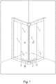
- FIG. 1 which shows an application position of a shower door sliding device in a shower door of the present invention, such as A, B, C, and D.
- an embodiment of the present invention includes a rail 10, a pulley 20, a pulley bracket 30, magnetic members 40, a pulley seat 50, a pulley seat fixing member 70 and a decorative cap 80 and the like, wherein the pulley bracket 30 is slidably arranged on the rail 10 via the pulley 20, the pulley seat 50 cooperates with the pulley seat fixing member 70 to be fixed to a movable door sheet 60, a plurality of the magnetic members 40 may be arranged, the pulley bracket 30 and the pulley seat 50 are respectively provided with the magnetic members 40, and the movable door sheet 60 and the pulley bracket 30 may be secured to each other by magnetic attraction of the magnetic members 40, thereby ensuring linearly relative sliding of the movable door sheet 60 along the rail 10. An external force acts on the movable door sheet 60 to separate the magnetic members 40, so as to achieve separation between the movable door sheet 60 and the rail 10.
- an interior of the rail 10 is a sliding channel 106 formed by a substantially C-sectioned groove wall 105 and used for the pulley 20 to roll therein, the lower part of one side of the sliding channel 106 has an opening 109, a decorative plate 104 is arranged on the outer side of the sliding channel 106, an open cavity 107 is arranged on the upper part of the sliding channel 106, and other sealing members for the movable door sheet can be installed.
- a screw hole 108 is arranged on an internal corner between an outer wall 103 and a bottom wall 101 of the rail 10.
- the magnetic member 40 is installed on one side of a body 301 of the pulley bracket 30, a bending plate 302 extends upwardly from one side of the bottom of the body 301, and screw holes 303 are arranged on the top of the bending plate 302 to install the pulleys 20.
- the pulley bracket 30 gets into the sliding channel 106 from the opening 109 by using the bending plate 302, and sets the pulleys 20 into the sliding channel 106.
- the decorative plate 104 hides the sliding channel 106 and the pulleys 20, which achieves aesthetic effects.
- the pulley bracket 30 has a substantially plate-shaped body 307, more than one (there are two in the embodiment) blind holes 306 are arranged on the back side of the body 307, the magnetic members 40 are installed within the blind holes 306, a baffle plate 304 extends out from an edge of the body 307 along a direction away from the bending plate 302, the baffle plate 304 and the body 307 form an accommodating chamber 305, and a size of the accommodating chamber 305 is adapted to that of the pulley seat 50 to accommodate the pulley seat 50.
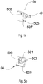
- the pulley seat 50 has a body plate 501, more than one (there are two in the embodiment) blind holes 502 are arranged on the back side of the body plate 501, the magnetic members 40 are arranged within the blind holes 502, a screw hole 506 is arranged on the body plate 501, and the pulley seat 50 is fixed to the movable door 60 by a screw (not shown), a baffle plate 505 extends out from the lower part of the body plate 501 in a direction perpendicular to a plane at which the body plate 501 is located, and the baffle plate 505 is in contact with an edge of the movable door sheet 60, to prevent the pulley seat 50 from rotating relative to the movable door sheet 60.
- Guide parts 507 are arranged on both sides of the body plate 501.
- the pulley seat fixing member 70 has a body plate 701, a screw hole 702 is formed on the body plate 701, and the pulley seat fixing member 70 is fixed to the movable door 60 by a screw 704, a baffle plate 703 extends out from the lower part of the body plate 701 in a direction perpendicular to a plane at which the body plate 701 is located, and the baffle plate 703 is in contact with an edge of the movable door sheet 60, to prevent the pulley seat fixing member 70 from rotating relative to the movable door sheet 60.
- a decorative cap 80 may be disposed on an exterior of the pulley seat fixing member 70. It should be stated that the pulley seat fixing member 70 and the decorative cap 80 are not essential, for example, the pulley seat 50 can be fixed to the movable door sheet 60 in an adhesive manner.
- the hidden easy-to-clean shower door sliding device of the present invention can be manufactured and used in industry; therefore the present invention possesses industrial applicability.
Landscapes
- Health & Medical Sciences (AREA)
- Public Health (AREA)
- Engineering & Computer Science (AREA)
- Mechanical Engineering (AREA)
- Epidemiology (AREA)
- General Health & Medical Sciences (AREA)
- Civil Engineering (AREA)
- Structural Engineering (AREA)
- Support Devices For Sliding Doors (AREA)
- Wing Frames And Configurations (AREA)
Applications Claiming Priority (1)
| Application Number | Priority Date | Filing Date | Title |
|---|---|---|---|
| PCT/CN2016/072682 WO2017128279A1 (fr) | 2016-01-29 | 2016-01-29 | Appareil pour faire coulisser une porte de douche, facile à nettoyer, de type dissimulé |
Publications (2)
| Publication Number | Publication Date |
|---|---|
| EP3239444A1 true EP3239444A1 (fr) | 2017-11-01 |
| EP3239444A4 EP3239444A4 (fr) | 2018-02-21 |
Family
ID=56216030
Family Applications (1)
| Application Number | Title | Priority Date | Filing Date |
|---|---|---|---|
| EP16871753.6A Withdrawn EP3239444A4 (fr) | 2016-01-29 | 2016-01-29 | Appareil pour faire coulisser une porte de douche, facile à nettoyer, de type dissimulé |
Country Status (4)
| Country | Link |
|---|---|
| US (1) | US20180320426A1 (fr) |
| EP (1) | EP3239444A4 (fr) |
| CN (1) | CN105683470A (fr) |
| WO (1) | WO2017128279A1 (fr) |
Cited By (1)
| Publication number | Priority date | Publication date | Assignee | Title |
|---|---|---|---|---|
| CN107995935A (zh) * | 2017-11-06 | 2018-05-04 | 佛山市爱迪尔卫浴有限公司 | 一种导向夹组件及淋浴门 |
Families Citing this family (9)
| Publication number | Priority date | Publication date | Assignee | Title |
|---|---|---|---|---|
| EP3312373B1 (fr) * | 2016-09-08 | 2019-05-08 | Ideal Sanitary Ware Co., Ltd. | Dispositif de coulissement inférieur facile à nettoyer pour porte de douche |
| CN106618317A (zh) * | 2016-12-05 | 2017-05-10 | 平湖市欧迪雅厨卫设备有限公司 | 一种新型防滑淋浴房 |
| GB201702042D0 (en) * | 2017-02-08 | 2017-03-22 | Kohler Mira Ltd | A detachable guide assembly for a shower enclosure door |
| CN110199077A (zh) * | 2019-04-28 | 2019-09-03 | 佛山市理想卫浴有限公司 | 滑轮组件隐藏式淋浴门 |
| CN110219541A (zh) * | 2019-06-20 | 2019-09-10 | 佛山市理想卫浴有限公司 | 滑轮组件及淋浴门组件 |
| CN111877936B (zh) * | 2020-08-26 | 2024-08-30 | 福建西河卫浴科技有限公司 | 一种电动淋浴房门 |
| AU2020469890B2 (en) * | 2020-09-22 | 2024-12-19 | Foshan Ideal Co., Ltd. | Hidden-type shower door with small rail sliding assembly |
| AT524703B1 (de) * | 2021-02-02 | 2024-01-15 | Artweger Gmbh & Co Kg | Bodenführungsvorrichtung für eine Schiebetüranordnung |
| US20260103942A1 (en) * | 2024-10-10 | 2026-04-16 | Foshan Lanfeilin Sanitary Ware Co., Ltd. | FRAMELESS HIDDEN wheel SLIDABLE DOOR |
Family Cites Families (8)
| Publication number | Priority date | Publication date | Assignee | Title |
|---|---|---|---|---|
| US4575966A (en) * | 1984-08-27 | 1986-03-18 | Jarrow Products, Inc. | Magnetically sealed sliding window assembly |
| CN2567319Y (zh) * | 2002-05-17 | 2003-08-20 | 危五祥 | 上轨道滑轮 |
| DE202004014466U1 (de) * | 2004-09-15 | 2004-11-25 | Pauli + Sohn Gmbh Metallwaren | Schiebetürführungsbeschlag und Schiebetüreinheit |
| CN202401908U (zh) * | 2012-01-17 | 2012-08-29 | 中山市雅立洁具有限公司 | 一种玻璃锁墙夹具 |
| CN203476042U (zh) * | 2013-07-30 | 2014-03-12 | 佛山市理想卫浴有限公司 | 具有自动关门功能的淋浴门组件 |
| CN203476035U (zh) * | 2013-07-30 | 2014-03-12 | 佛山市理想卫浴有限公司 | 一种滑轮机构 |
| CN204212588U (zh) * | 2014-11-07 | 2015-03-18 | 佛山市恒洁卫浴有限公司 | 一种淋浴房的导轨结构 |
| CN204691512U (zh) * | 2015-02-10 | 2015-10-07 | 福建西河卫浴科技有限公司 | 一种防撞止转淋浴滑轮组件 |
-
2016
- 2016-01-29 EP EP16871753.6A patent/EP3239444A4/fr not_active Withdrawn
- 2016-01-29 US US15/540,204 patent/US20180320426A1/en not_active Abandoned
- 2016-01-29 CN CN201680000092.0A patent/CN105683470A/zh active Pending
- 2016-01-29 WO PCT/CN2016/072682 patent/WO2017128279A1/fr not_active Ceased
Cited By (2)
| Publication number | Priority date | Publication date | Assignee | Title |
|---|---|---|---|---|
| CN107995935A (zh) * | 2017-11-06 | 2018-05-04 | 佛山市爱迪尔卫浴有限公司 | 一种导向夹组件及淋浴门 |
| CN107995935B (zh) * | 2017-11-06 | 2020-05-01 | 佛山市爱迪尔卫浴有限公司 | 一种导向夹组件及淋浴门 |
Also Published As
| Publication number | Publication date |
|---|---|
| US20180320426A1 (en) | 2018-11-08 |
| CN105683470A (zh) | 2016-06-15 |
| WO2017128279A1 (fr) | 2017-08-03 |
| EP3239444A4 (fr) | 2018-02-21 |
Similar Documents
| Publication | Publication Date | Title |
|---|---|---|
| US20180320426A1 (en) | Hidden easy-to-clean shower door sliding device | |
| US9486114B2 (en) | Removable header for a shower door track assembly | |
| US20180020882A1 (en) | Guide block for glass panel | |
| GB2532097A (en) | A three-section synchronous concealed slide rail | |
| EP3488747B1 (fr) | Ensemble support réglable réversible pour panneau de verre | |
| EP3537942B1 (fr) | Ensemble de guidage amovible pour porte de cabine de douche | |
| US20060049730A1 (en) | Drawer frame | |
| ITMC20110058A1 (it) | Cassetto perfezionato con anta frontale corredato di attrezzatura di regolazione e bloccaggio per detta anta frontale. | |
| CN105992856A (zh) | 导向夹组件及淋浴门 | |
| CN105492714A (zh) | 淋浴门组件及淋浴门 | |
| CN104329895B (zh) | 抽屉组件及冰箱 | |
| US9896245B1 (en) | Sliding door and track assembly | |
| EP3312373B1 (fr) | Dispositif de coulissement inférieur facile à nettoyer pour porte de douche | |
| CN205639184U (zh) | 一种滑动卡扣机构及其空调器 | |
| KR20170026998A (ko) | 욕실장용 롤러 브래킷과 프레임의 조립장치 | |
| EP3299729B1 (fr) | Assemblage d'une hotte et d'un placard | |
| JP2004011200A (ja) | 扉又は引き出しの持ち手構造 | |
| CN201011144Y (zh) | 一种安装防撞式淋浴房 | |
| KR20170056355A (ko) | 욕실용 수납장 | |
| CN101503936A (zh) | 一种带有内置物架的淋浴房门 | |
| WO2006111772A3 (fr) | Ameliorations pour bain-douche | |
| KR101616092B1 (ko) | 가구용 슬라이딩 도어의 고정 브래킷 | |
| KR200334958Y1 (ko) | 장식장 여닫이문장치 | |
| JP5849244B2 (ja) | キャビネットにおける幕板の変形抑制構造 | |
| KR101592697B1 (ko) | 전통 건축물 식당의 배식구 개폐문 설치구조 |
Legal Events
| Date | Code | Title | Description |
|---|---|---|---|
| STAA | Information on the status of an ep patent application or granted ep patent |
Free format text: STATUS: UNKNOWN |
|
| STAA | Information on the status of an ep patent application or granted ep patent |
Free format text: STATUS: THE INTERNATIONAL PUBLICATION HAS BEEN MADE |
|
| PUAI | Public reference made under article 153(3) epc to a published international application that has entered the european phase |
Free format text: ORIGINAL CODE: 0009012 |
|
| STAA | Information on the status of an ep patent application or granted ep patent |
Free format text: STATUS: REQUEST FOR EXAMINATION WAS MADE |
|
| 17P | Request for examination filed |
Effective date: 20170613 |
|
| AK | Designated contracting states |
Kind code of ref document: A1 Designated state(s): AL AT BE BG CH CY CZ DE DK EE ES FI FR GB GR HR HU IE IS IT LI LT LU LV MC MK MT NL NO PL PT RO RS SE SI SK SM TR |
|
| AX | Request for extension of the european patent |
Extension state: BA ME |
|
| A4 | Supplementary search report drawn up and despatched |
Effective date: 20180124 |
|
| RIC1 | Information provided on ipc code assigned before grant |
Ipc: E05D 15/06 20060101AFI20180117BHEP Ipc: A47K 3/30 20060101ALI20180117BHEP |
|
| STAA | Information on the status of an ep patent application or granted ep patent |
Free format text: STATUS: EXAMINATION IS IN PROGRESS |
|
| 17Q | First examination report despatched |
Effective date: 20190320 |
|
| DAV | Request for validation of the european patent (deleted) | ||
| DAX | Request for extension of the european patent (deleted) | ||
| STAA | Information on the status of an ep patent application or granted ep patent |
Free format text: STATUS: THE APPLICATION IS DEEMED TO BE WITHDRAWN |
|
| 18D | Application deemed to be withdrawn |
Effective date: 20190731 |