EP3239607A1 - Pulso-réacteur comprenant une flamme à pulser en particulier pour le traitement thermique de matériau ou la synthèse de matériaux - Google Patents
Pulso-réacteur comprenant une flamme à pulser en particulier pour le traitement thermique de matériau ou la synthèse de matériaux Download PDFInfo
- Publication number
- EP3239607A1 EP3239607A1 EP17000515.1A EP17000515A EP3239607A1 EP 3239607 A1 EP3239607 A1 EP 3239607A1 EP 17000515 A EP17000515 A EP 17000515A EP 3239607 A1 EP3239607 A1 EP 3239607A1
- Authority
- EP
- European Patent Office
- Prior art keywords
- flame
- burner
- diffuser
- pulsating
- vibrating
- Prior art date
- Legal status (The legal status is an assumption and is not a legal conclusion. Google has not performed a legal analysis and makes no representation as to the accuracy of the status listed.)
- Withdrawn
Links
- 239000000463 material Substances 0.000 title abstract description 46
- 230000015572 biosynthetic process Effects 0.000 title abstract description 11
- 238000003786 synthesis reaction Methods 0.000 title abstract description 10
- 238000000034 method Methods 0.000 claims abstract description 11
- 230000008569 process Effects 0.000 claims abstract description 7
- 238000002485 combustion reaction Methods 0.000 claims description 54
- 239000007789 gas Substances 0.000 claims description 33
- 239000000203 mixture Substances 0.000 claims description 22
- 239000000446 fuel Substances 0.000 claims description 14
- 239000002994 raw material Substances 0.000 claims description 12
- 238000006243 chemical reaction Methods 0.000 claims description 5
- 239000002737 fuel gas Substances 0.000 claims description 4
- 238000007669 thermal treatment Methods 0.000 claims description 3
- 230000010355 oscillation Effects 0.000 abstract description 32
- 230000010349 pulsation Effects 0.000 abstract description 14
- 238000004519 manufacturing process Methods 0.000 abstract description 4
- 238000005516 engineering process Methods 0.000 abstract description 2
- 230000002860 competitive effect Effects 0.000 abstract 1
- 230000002265 prevention Effects 0.000 abstract 1
- 206010016754 Flashback Diseases 0.000 description 11
- 238000011144 upstream manufacturing Methods 0.000 description 7
- 230000008859 change Effects 0.000 description 6
- 230000008901 benefit Effects 0.000 description 5
- 238000010304 firing Methods 0.000 description 5
- 230000000737 periodic effect Effects 0.000 description 5
- 238000001816 cooling Methods 0.000 description 4
- 230000006378 damage Effects 0.000 description 4
- VNWKTOKETHGBQD-UHFFFAOYSA-N methane Chemical compound C VNWKTOKETHGBQD-UHFFFAOYSA-N 0.000 description 4
- 239000007787 solid Substances 0.000 description 4
- 230000003068 static effect Effects 0.000 description 4
- 230000007423 decrease Effects 0.000 description 3
- 238000009792 diffusion process Methods 0.000 description 3
- 238000002156 mixing Methods 0.000 description 3
- 239000002245 particle Substances 0.000 description 3
- 239000000126 substance Substances 0.000 description 3
- XLYOFNOQVPJJNP-UHFFFAOYSA-N water Substances O XLYOFNOQVPJJNP-UHFFFAOYSA-N 0.000 description 3
- QVGXLLKOCUKJST-UHFFFAOYSA-N atomic oxygen Chemical compound [O] QVGXLLKOCUKJST-UHFFFAOYSA-N 0.000 description 2
- 239000000919 ceramic Substances 0.000 description 2
- 230000003247 decreasing effect Effects 0.000 description 2
- 238000010586 diagram Methods 0.000 description 2
- 238000010438 heat treatment Methods 0.000 description 2
- 239000007788 liquid Substances 0.000 description 2
- 239000001301 oxygen Substances 0.000 description 2
- 229910052760 oxygen Inorganic materials 0.000 description 2
- 230000000630 rising effect Effects 0.000 description 2
- MYMOFIZGZYHOMD-UHFFFAOYSA-N Dioxygen Chemical compound O=O MYMOFIZGZYHOMD-UHFFFAOYSA-N 0.000 description 1
- LFQSCWFLJHTTHZ-UHFFFAOYSA-N Ethanol Chemical compound CCO LFQSCWFLJHTTHZ-UHFFFAOYSA-N 0.000 description 1
- UFHFLCQGNIYNRP-UHFFFAOYSA-N Hydrogen Chemical compound [H][H] UFHFLCQGNIYNRP-UHFFFAOYSA-N 0.000 description 1
- 230000005856 abnormality Effects 0.000 description 1
- 230000009471 action Effects 0.000 description 1
- 238000004873 anchoring Methods 0.000 description 1
- 230000004323 axial length Effects 0.000 description 1
- 230000008033 biological extinction Effects 0.000 description 1
- 238000001354 calcination Methods 0.000 description 1
- 239000002131 composite material Substances 0.000 description 1
- 239000002826 coolant Substances 0.000 description 1
- 238000013016 damping Methods 0.000 description 1
- 238000001035 drying Methods 0.000 description 1
- 230000000694 effects Effects 0.000 description 1
- 238000002635 electroconvulsive therapy Methods 0.000 description 1
- 239000003344 environmental pollutant Substances 0.000 description 1
- 239000008236 heating water Substances 0.000 description 1
- 239000001257 hydrogen Substances 0.000 description 1
- 229910052739 hydrogen Inorganic materials 0.000 description 1
- 239000008235 industrial water Substances 0.000 description 1
- 238000011068 loading method Methods 0.000 description 1
- 230000007246 mechanism Effects 0.000 description 1
- 239000003345 natural gas Substances 0.000 description 1
- 239000007800 oxidant agent Substances 0.000 description 1
- 231100000719 pollutant Toxicity 0.000 description 1
- 238000000746 purification Methods 0.000 description 1
- 230000009257 reactivity Effects 0.000 description 1
- 230000009467 reduction Effects 0.000 description 1
- 210000002023 somite Anatomy 0.000 description 1
- 230000005654 stationary process Effects 0.000 description 1
- 239000000725 suspension Substances 0.000 description 1
- 230000008646 thermal stress Effects 0.000 description 1
- 230000036962 time dependent Effects 0.000 description 1
- 230000001052 transient effect Effects 0.000 description 1
- 230000007704 transition Effects 0.000 description 1
Images
Classifications
-
- F—MECHANICAL ENGINEERING; LIGHTING; HEATING; WEAPONS; BLASTING
- F23—COMBUSTION APPARATUS; COMBUSTION PROCESSES
- F23C—METHODS OR APPARATUS FOR COMBUSTION USING FLUID FUEL OR SOLID FUEL SUSPENDED IN A CARRIER GAS OR AIR
- F23C15/00—Apparatus in which combustion takes place in pulses influenced by acoustic resonance in a gas mass
-
- F—MECHANICAL ENGINEERING; LIGHTING; HEATING; WEAPONS; BLASTING
- F23—COMBUSTION APPARATUS; COMBUSTION PROCESSES
- F23C—METHODS OR APPARATUS FOR COMBUSTION USING FLUID FUEL OR SOLID FUEL SUSPENDED IN A CARRIER GAS OR AIR
- F23C7/00—Combustion apparatus characterised by arrangements for air supply
- F23C7/002—Combustion apparatus characterised by arrangements for air supply the air being submitted to a rotary or spinning motion
-
- F—MECHANICAL ENGINEERING; LIGHTING; HEATING; WEAPONS; BLASTING
- F23—COMBUSTION APPARATUS; COMBUSTION PROCESSES
- F23C—METHODS OR APPARATUS FOR COMBUSTION USING FLUID FUEL OR SOLID FUEL SUSPENDED IN A CARRIER GAS OR AIR
- F23C99/00—Subject-matter not provided for in other groups of this subclass
- F23C99/003—Combustion process using sound or vibrations
-
- F—MECHANICAL ENGINEERING; LIGHTING; HEATING; WEAPONS; BLASTING
- F26—DRYING
- F26B—DRYING SOLID MATERIALS OR OBJECTS BY REMOVING LIQUID THEREFROM
- F26B23/00—Heating arrangements
- F26B23/02—Heating arrangements using combustion heating
- F26B23/026—Heating arrangements using combustion heating with pulse combustion, e.g. pulse jet combustion drying of particulate materials
-
- F—MECHANICAL ENGINEERING; LIGHTING; HEATING; WEAPONS; BLASTING
- F26—DRYING
- F26B—DRYING SOLID MATERIALS OR OBJECTS BY REMOVING LIQUID THEREFROM
- F26B3/00—Drying solid materials or objects by processes involving the application of heat
- F26B3/02—Drying solid materials or objects by processes involving the application of heat by convection, i.e. heat being conveyed from a heat source to the materials or objects to be dried by a gas or vapour, e.g. air
- F26B3/10—Drying solid materials or objects by processes involving the application of heat by convection, i.e. heat being conveyed from a heat source to the materials or objects to be dried by a gas or vapour, e.g. air the gas or vapour carrying the materials or objects to be dried with it
-
- F—MECHANICAL ENGINEERING; LIGHTING; HEATING; WEAPONS; BLASTING
- F23—COMBUSTION APPARATUS; COMBUSTION PROCESSES
- F23C—METHODS OR APPARATUS FOR COMBUSTION USING FLUID FUEL OR SOLID FUEL SUSPENDED IN A CARRIER GAS OR AIR
- F23C2205/00—Pulsating combustion
Definitions
- the invention relates to a vibrating furnace for a material treatment or material synthesis (pulse dryer, pulse combustor, Pulsationsreaktor), the at least one burner, at least one pulsating flame, a combustion chamber and at least one resonant gas column (eg in the combustion chamber or in a resonance tube), in the raw material to be treated can be introduced and removed from it, and a corresponding method for its operation.
- a material treatment or material synthesis pulse dryer, pulse combustor, Pulsationsreaktor
- the at least one burner at least one pulsating flame
- a combustion chamber and at least one resonant gas column eg in the combustion chamber or in a resonance tube
- combustion process is at least an order of magnitude smaller than the average sizes of the combustion process (such as average flow velocity, mean temperature of the combustion process), with the exception of minor turbulent fluctuations Flame or the exhaust gas flow, mean static pressure in the combustion chamber, etc.), on average on a time-constant basis.
- the conversion of the fuel used is continuous over time and, as a consequence, also the heat release from the combustion process and the mass flow of exhaust gas arising (combustion products) have constant values for a fixed burner setting.
- the heat release rate (s) of the flame (s) and thus the thermal firing efficiency of the incinerator as well as the exhaust flow into and out of the combustion chamber and the static pressure in the combustion chamber itself become periodically unsteady, ie oscillating.
- combustion instabilities often causes a relation to the stationary operation of the furnace changed pollutant emission behavior and causes not only increased noise pollution of the plant environment but also a significantly increased mechanical and / or thermal stress on the plant structure (eg combustion chamber walls, combustion chamber lining, etc.), the up to Destruction of the firing or individual components may result.
- plant structure eg combustion chamber walls, combustion chamber lining, etc.
- the raw material may also be a mixture of raw materials.
- the raw material or the raw material mixture can be present both in solid and in liquid or in gaseous or vaporous form.
- thermo shock treatment in pulsating hot gas flows.
- any change in both the mass flows of the abandoned raw materials and the specific material properties of different educts change the amplitude of the vibration of the pulsating hot gas flow at material application and thus the result of the material treatment.
- flashback is to be understood as follows:
- a vibratory firing which is driven by the process described above, in particular self-excited combustion instabilities (flame oscillations)
- combustion instabilities flame oscillations
- there is a temporal-periodic change in the mass flow of fuel gas / air mixture leaving the burner (For example, in the case of premix combustion) and thus also to a temporal-periodic change in the burner exit velocity (axial velocity component)
- the flame speed (firing rate) of the effluent from the burner mixture at a constant composition and thus constant air ratio of the premix has a constant value.
- flashback is understood to mean instantaneous or even permanent burning of the flame within the burner and not, as actually desired, in a raised, stable position axially after burner exit outside the burner.
- shutting down the equipment due to an unwanted flashback will also result in the material (product) that was last thermally treated and / or synthesized under undefined thermal conditions being rejected.
- the present invention is therefore based on the object of specifying a device with which the amplitudes of the oscillation of the hot gas flow in the combustion chamber can assume high values during operation of a pulsation reactor in order thus also to be able to increase, for example, the achievable product throughput rates and thus the reactor throughput. and at the same time the risk of accidental kickback of the pulsating flame in the burner is effectively avoided.
- a method for their operation to be proposed.
- the burner is designed to produce a pulsating flame to produce a pulsating hot gas flow as a swirl burner and has a diffuser as an element at its outlet.
- a method according to the invention is therefore distinguished by the fact that the pulsating fuel / air mixture flowing to the pulsating flame is conducted through a swirl burner and a diffuser adjoining it.
- the diffuser is, in particular, a conical, preferably metal-shaped, diffuser whose free cross-sectional area increases in the axial flow direction.
- An opening half-angle of the element according to the invention referred to as a diffuser, can be chosen in the range between 3 degrees and 45 degrees.
- an axial extent of the diffuser can be 0.5 times to 10 times the free diameter of the burner outlet.
- the diffuser can be positioned directly after a swirl generator on the burner. But it is also possible initially to provide at the outlet of the swirl generator nor a cylindrical tube element, which is then followed in the axial flow direction of the diffuser.
- the invention is based on the surprising finding that when using a pulsating premix spiral flame or a pulsating, fast mixing diffusion swirl flame as the "drive" of a vibrating or pulsation reactor to produce the pulsating hot gas stream required in this for the material treatment or synthesis a burner outlet designed as a diffuser, with the correct choice of diffuser length and diffuser opening angle, will automatically prevent flashback of the pulsating flame into the burner - even at very high amplitudes of the combustion oscillation in the combustion chamber.
- One possible explanatory model of the effect of the invention as an autoadaptive flashback fuse is based on the fact that in the upstream traveling of the pulsating flame in the moments of low burner Ausström Ober vibration period, the flame itself blocks a part of the free flow cross-sectional area of the diffuser. This is based on the finding that, in the case of a swirl burner, the area occupied by the flame or the internal backflow zone of the swirl flow, which is subject to the flame (perpendicular to the axial direction), is substantially independent of the outflow velocity of the fuel gas / air present in the axial direction of the burner -Gemisches is.
- the problem of unwanted flashback by the pulsating flow in a vibrating or pulsation reactor is only relevant if the flame is fully pre-mixed (fuel and combustion air are spatially mixed with each other before the burner molecularly) or if they burns as a fast-mixing diffusion flame. In the latter case, e.g. a nozzle mixing flame, in the fuel and combustion air only within the burner - preferably at the burner outlet - are merged.
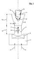
- the fuel and combustion air separated 2 or pre-mixed fuel / air mixture 2 is supplied via at least one line not shown here.
- fuel By fuel is meant e.g. Fuel gases such as natural gas, methane, hydrogen or liquid fuels such as alcohol, etc.
- combustion air is generally understood in the context of the present invention, an oxidizing agent, which provides the oxygen required for combustion. In addition to air, this includes, for example, pure oxygen or oxygen-enriched air, etc.
- This combustion air stream or this fuel / air mixture is conducted via a swirl generator 3 within the swirl burner 1, so that the mass flow 5 flowing out of the burner outlet 4 has a rotational movement 6 in the circumferential direction (tangential velocity component or "swirl") apart from a movement in the axial direction.
- the mass flow 5 flows into a diffuser 7.
- the walls of the diffuser have a substantially conical shape with an opening half-angle 8.
- This opening half-angle 8 is in a range between 3 ° and 45 ° and is measured with respect to the axial direction.
- the burner outlet 4 has a substantially circular cross-section and may have an axial extent 9, which is preferably approximately in the range between 0 and 0.5 m.
- the axial length 10 of the conical or frusto-conical diffuser 7 may have an amount of about 0.1 to 1 m. It is thus based on the dimensions of the burner outlet 4 between about 0.5 times and 10 times the free diameter of the burner outlet.
- a swirl flame 12 is formed in the mass flow 5 from the outflowing fuel / air mixture.
- This swirl flame 12 is characterized in particular by a central greedström which is an important characteristic of a spin-stabilized flame.
- the flame 12 burns in a pulsating manner into a combustion chamber (not shown here), which adjoins the diffuser 7 in terms of flow, and generates there a swinging hot gas flow.
- This hot gas flow is required to give up a lot of material for material treatment or material synthesis.
- This material after being treated or synthesized in the hot gas flow, is finally separated again, for example, in a cyclone or a hot gas filter, which are also not shown.
- the pulsation of the flame 12 is self-excited and acts in the composite burner - flame - combustion chamber - reaction chamber - separator on the incoming mass flow 5 back.
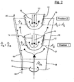
- the mass flow emerging from the burner has a time-dependent - usually approximately sinusoidal - time course).
- the axial velocity of the burner exit flow (axial flow component of the burner outflow) changes, while at the same time the flame speed 14 of the forming flame 12 remains constant.
- the flame speed is the speed at which the flame 12 opposes the outflow direction of the incoming fuel / air mixture spreads in this.
- the flame 12 is essentially constant in its geometric dimensions transversely to the outflow direction, regardless of its axial position. This is related to the special properties of a spin-stabilized flame, as already mentioned above.
- the free annular surface 17 as explained due to the shape of the diffuser 7 is smaller than the free annular surface 15 in the position 2.
- the axial flow velocity U 1 increases in the same, of the characterized by the central remindströmzone spin-stabilized flame 12, non-permeable surface in the Position 1, the axial flow velocity U 1 and thus there also increases the axial pulse current ⁇ . 1
- the axial pulse current ⁇ 1 is thus greater than the axial pulse current ⁇ 2 .
- the wall 16 of the diffuser 7 and the wall 18 of the burner outlet 4 either uncooled or as in the Fig. 2 can be seen on the left side, may be provided with a cooling 19, which is for example caused by a stream 20 of air or water, which is passed through the cooling 19.
- the device described here and its operation make it possible to set the oscillation amplitude of a vibrating fire reactor to high values, in particular during idling of the system (ie without material feed), without having to carry the risk of a flashback in the burner, since such a flashback by the invention provided on the swirl burner used diffuser is reliably prevented.
Landscapes
- Engineering & Computer Science (AREA)
- Chemical & Material Sciences (AREA)
- Combustion & Propulsion (AREA)
- Mechanical Engineering (AREA)
- General Engineering & Computer Science (AREA)
- Life Sciences & Earth Sciences (AREA)
- Sustainable Development (AREA)
- Microbiology (AREA)
- Fluidized-Bed Combustion And Resonant Combustion (AREA)
Applications Claiming Priority (1)
| Application Number | Priority Date | Filing Date | Title |
|---|---|---|---|
| DE102016005155.8A DE102016005155B4 (de) | 2016-04-28 | 2016-04-28 | Schwingfeuerreaktor mit pulsierender Flamme und Verfahren für eine thermische Materialbehandlung oder Materialsynthese |
Publications (1)
| Publication Number | Publication Date |
|---|---|
| EP3239607A1 true EP3239607A1 (fr) | 2017-11-01 |
Family
ID=58461036
Family Applications (1)
| Application Number | Title | Priority Date | Filing Date |
|---|---|---|---|
| EP17000515.1A Withdrawn EP3239607A1 (fr) | 2016-04-28 | 2017-03-29 | Pulso-réacteur comprenant une flamme à pulser en particulier pour le traitement thermique de matériau ou la synthèse de matériaux |
Country Status (3)
| Country | Link |
|---|---|
| US (1) | US20170314778A1 (fr) |
| EP (1) | EP3239607A1 (fr) |
| DE (1) | DE102016005155B4 (fr) |
Families Citing this family (5)
| Publication number | Priority date | Publication date | Assignee | Title |
|---|---|---|---|---|
| DE102018211652A1 (de) * | 2018-07-12 | 2020-01-16 | Ibu-Tec Advanced Materials Ag | Vorrichtung zur Herstellung von Partikeln |
| DE102020204199A1 (de) * | 2020-03-31 | 2021-09-30 | Glatt Ingenieurtechnik Gesellschaft mit beschränkter Haftung | Reaktorsystem |
| GB2607736B (en) * | 2021-06-08 | 2024-09-11 | Hydrogen Tech Llc | Burner assemblies and methods |
| DE102021115957B3 (de) | 2021-06-21 | 2022-10-20 | Horst Büchner | Vorrichtung zum Vorwärmen metallischer Werkstücke, insbesondere der Endstücke von miteinander zu verschweißenden Bahnschienen |
| ES2999292T3 (en) | 2022-01-27 | 2025-02-25 | Ekonek Innovacion En Valorizacion Desubproductos S L | Pulse combustion dryer |
Citations (3)
| Publication number | Priority date | Publication date | Assignee | Title |
|---|---|---|---|---|
| US3276505A (en) * | 1963-02-23 | 1966-10-04 | Huber | Resonant burner |
| DE19545310A1 (de) * | 1995-12-05 | 1997-06-12 | Asea Brown Boveri | Vormischbrenner |
| EP2092976A1 (fr) * | 2008-01-30 | 2009-08-26 | IBU-tec advanced materials AG | Procédé de fabrication de particules fines |
Family Cites Families (2)
| Publication number | Priority date | Publication date | Assignee | Title |
|---|---|---|---|---|
| DE19934612A1 (de) * | 1999-07-23 | 2001-01-25 | Abb Alstom Power Ch Ag | Verfahren zur aktiven Unterdrückung von strömungsmechanischen Instabilitäten in einem Verbrennungssystem sowie Verbrennungssystem zur Durchführung des Verfahrens |
| EP2107310A1 (fr) * | 2008-04-01 | 2009-10-07 | Siemens Aktiengesellschaft | Brûleur |
-
2016
- 2016-04-28 DE DE102016005155.8A patent/DE102016005155B4/de active Active
-
2017
- 2017-03-29 EP EP17000515.1A patent/EP3239607A1/fr not_active Withdrawn
- 2017-04-27 US US15/499,192 patent/US20170314778A1/en not_active Abandoned
Patent Citations (3)
| Publication number | Priority date | Publication date | Assignee | Title |
|---|---|---|---|---|
| US3276505A (en) * | 1963-02-23 | 1966-10-04 | Huber | Resonant burner |
| DE19545310A1 (de) * | 1995-12-05 | 1997-06-12 | Asea Brown Boveri | Vormischbrenner |
| EP2092976A1 (fr) * | 2008-01-30 | 2009-08-26 | IBU-tec advanced materials AG | Procédé de fabrication de particules fines |
Also Published As
| Publication number | Publication date |
|---|---|
| DE102016005155B4 (de) | 2024-05-08 |
| US20170314778A1 (en) | 2017-11-02 |
| DE102016005155A1 (de) | 2017-11-02 |
Similar Documents
| Publication | Publication Date | Title |
|---|---|---|
| DE102015005224B4 (de) | Verfahren und Vorrichtung zur Einstellung der Schwingungsamplituden von Schwingfeueranlagen | |
| EP3239607A1 (fr) | Pulso-réacteur comprenant une flamme à pulser en particulier pour le traitement thermique de matériau ou la synthèse de matériaux | |
| DE3306483C2 (fr) | ||
| WO1999037951A1 (fr) | Dispositif permettant de supprimer les oscillations de la flamme/pression dans un foyer, notamment une turbine a gaz | |
| DE4416650A1 (de) | Verbrennungsverfahren für atmosphärische Feuerungsanlagen | |
| WO2005095863A1 (fr) | Brûleur | |
| EP0623786A1 (fr) | Chambre de combustion | |
| DE4426351A1 (de) | Brennkammer | |
| EP1507119A1 (fr) | Brûleur et méthode de fonctionnement d'une turbine à gaz | |
| EP1182398A1 (fr) | Procédé pour accroítre la stabilité fluidique d'un brûleur de prémélange ainsi que brûleur de prémélange pour mettre en oeuvre le procédé | |
| EP0995066A1 (fr) | Agencement de bruleurs pour une installation de chauffe, notamment une chambre de combustion de turbine a gaz | |
| DE4231866A1 (de) | Brenner und verfahren zum verbrennen von gas mit niedrigem brennwert | |
| EP0040690B1 (fr) | Dispositif pour la combustion de matières oxydables dans les gaz d'échappement | |
| EP0101462B1 (fr) | Bruleur pour carburants a l'etat poudreux, gazeux et/ou liquide | |
| DE3907347A1 (de) | Keramischer brenner | |
| DE2952502A1 (de) | Verfahren zur steuerung des verlaufs einer kontaktkinetischen flammenlosen verbrennung und kessel zur durchfuehrung dieses verfahrens | |
| DE2315821A1 (de) | Durchsink-vorerhitzer | |
| DE202008009650U1 (de) | Mehrstoff-Brenner | |
| DE19613777C2 (de) | Verbrennungsanlage und Nachverbrennungsverfahren | |
| EP0005714B1 (fr) | Brûleur pour la combustion du charbon broyé | |
| EP1893915B1 (fr) | Systeme bruleur et son mode de fonctionnement | |
| EP1001214A1 (fr) | Procédé pour empêcher la formation d'instabilités d'écoulement dans un brûleur | |
| EP2587148B1 (fr) | Chambre de combustion secondaire avec injection d'air secondaire | |
| DE3043286A1 (de) | Verbrennungseinrichtung zur verbrennung von stoerstoffen in abgasen | |
| DE102017118166B4 (de) | Brennerkopf, Brennersystem und Verwendung des Brennersystems |
Legal Events
| Date | Code | Title | Description |
|---|---|---|---|
| PUAI | Public reference made under article 153(3) epc to a published international application that has entered the european phase |
Free format text: ORIGINAL CODE: 0009012 |
|
| AK | Designated contracting states |
Kind code of ref document: A1 Designated state(s): AL AT BE BG CH CY CZ DE DK EE ES FI FR GB GR HR HU IE IS IT LI LT LU LV MC MK MT NL NO PL PT RO RS SE SI SK SM TR |
|
| AX | Request for extension of the european patent |
Extension state: BA ME |
|
| 17P | Request for examination filed |
Effective date: 20180427 |
|
| RBV | Designated contracting states (corrected) |
Designated state(s): AL AT BE BG CH CY CZ DE DK EE ES FI FR GB GR HR HU IE IS IT LI LT LU LV MC MK MT NL NO PL PT RO RS SE SI SK SM TR |
|
| STAA | Information on the status of an ep patent application or granted ep patent |
Free format text: STATUS: THE APPLICATION IS DEEMED TO BE WITHDRAWN |
|
| 18D | Application deemed to be withdrawn |
Effective date: 20191001 |