EP3239620A1 - Ventilateur d'extraction d'air à section de passage variable en cas d'incendie - Google Patents
Ventilateur d'extraction d'air à section de passage variable en cas d'incendie Download PDFInfo
- Publication number
- EP3239620A1 EP3239620A1 EP17168460.8A EP17168460A EP3239620A1 EP 3239620 A1 EP3239620 A1 EP 3239620A1 EP 17168460 A EP17168460 A EP 17168460A EP 3239620 A1 EP3239620 A1 EP 3239620A1
- Authority
- EP
- European Patent Office
- Prior art keywords
- passage
- normal
- air
- fan according
- outlet
- Prior art date
- Legal status (The legal status is an assumption and is not a legal conclusion. Google has not performed a legal analysis and makes no representation as to the accuracy of the status listed.)
- Granted
Links
Images

Classifications
-
- F—MECHANICAL ENGINEERING; LIGHTING; HEATING; WEAPONS; BLASTING
- F24—HEATING; RANGES; VENTILATING
- F24F—AIR-CONDITIONING; AIR-HUMIDIFICATION; VENTILATION; USE OF AIR CURRENTS FOR SCREENING
- F24F7/00—Ventilation
- F24F7/02—Roof ventilation
- F24F7/025—Roof ventilation with forced air circulation by means of a built-in ventilator
-
- F—MECHANICAL ENGINEERING; LIGHTING; HEATING; WEAPONS; BLASTING
- F04—POSITIVE - DISPLACEMENT MACHINES FOR LIQUIDS; PUMPS FOR LIQUIDS OR ELASTIC FLUIDS
- F04D—NON-POSITIVE-DISPLACEMENT PUMPS
- F04D27/00—Control, e.g. regulation, of pumps, pumping installations or pumping systems specially adapted for elastic fluids
- F04D27/002—Control, e.g. regulation, of pumps, pumping installations or pumping systems specially adapted for elastic fluids by varying geometry within the pumps, e.g. by adjusting vanes
-
- F—MECHANICAL ENGINEERING; LIGHTING; HEATING; WEAPONS; BLASTING
- F24—HEATING; RANGES; VENTILATING
- F24F—AIR-CONDITIONING; AIR-HUMIDIFICATION; VENTILATION; USE OF AIR CURRENTS FOR SCREENING
- F24F11/00—Control or safety arrangements
-
- F—MECHANICAL ENGINEERING; LIGHTING; HEATING; WEAPONS; BLASTING
- F24—HEATING; RANGES; VENTILATING
- F24F—AIR-CONDITIONING; AIR-HUMIDIFICATION; VENTILATION; USE OF AIR CURRENTS FOR SCREENING
- F24F11/00—Control or safety arrangements
- F24F11/30—Control or safety arrangements for purposes related to the operation of the system, e.g. for safety or monitoring
-
- F—MECHANICAL ENGINEERING; LIGHTING; HEATING; WEAPONS; BLASTING
- F24—HEATING; RANGES; VENTILATING
- F24F—AIR-CONDITIONING; AIR-HUMIDIFICATION; VENTILATION; USE OF AIR CURRENTS FOR SCREENING
- F24F7/00—Ventilation
- F24F7/02—Roof ventilation
-
- F—MECHANICAL ENGINEERING; LIGHTING; HEATING; WEAPONS; BLASTING
- F24—HEATING; RANGES; VENTILATING
- F24F—AIR-CONDITIONING; AIR-HUMIDIFICATION; VENTILATION; USE OF AIR CURRENTS FOR SCREENING
- F24F11/00—Control or safety arrangements
- F24F11/30—Control or safety arrangements for purposes related to the operation of the system, e.g. for safety or monitoring
- F24F11/32—Responding to malfunctions or emergencies
- F24F11/33—Responding to malfunctions or emergencies to fire, excessive heat or smoke
- F24F11/34—Responding to malfunctions or emergencies to fire, excessive heat or smoke by opening air passages
Definitions
- the present invention relates to an exhaust fan provided for renewing the air of a building, in particular for a dwelling or a tertiary building.
- Buildings receiving people including housing or tertiary premises such as schools or offices, usually include a ventilation system of the various rooms to renew the air, including a system for extracting air from the premises, and air inlets from outside to compensate for this extraction.
- the main purpose of room air renewal is to remove air pollutants related to the presence of occupants, the presence of equipment or machines used in these rooms, as well as those emitted by the building itself. even.
- the ventilation of the premises can be natural, with air ducts from different rooms to open to the outside, which have a thermal draw activated by the difference in natural pressure when the air is colder outside. When the outside temperature is higher the pressure differential between the inside and the outside is lost, and the air flow may be insufficient.
- Ventilation of the premises can also be achieved by a controlled mechanical ventilation called "VMC", comprising a turbine driven by an electric motor running continuously, which generates a vacuum to activate the flow in the air ducts opening to the outside.
- VMC controlled mechanical ventilation
- an intermediate ventilation system also called hybrid ventilation, comprises a turbine with a stationary low pressure drop in the duct, which is stopped when the thermal draft of the natural ventilation is sufficient, and which rotates at a speed variable adapted when the natural ventilation and insufficient to compensate the flow too low.
- the speed of the turbine can be adjusted automatically according to the outside temperature which activates the natural ventilation.
- the present invention proposes for this purpose an air extraction fan intended to be arranged on a building at the outlet of a ventilation circuit, having a normal passage for the exit of the air towards the outside, this fan being remarkable in that it comprises a deformable portion closing a passage to the outside, which deforms in temperature under the effect of hot gases in the fan during a fire, so as to form an additional outlet passage s' adding to the normal output passage to increase the total passage section outward.
- the exhaust fan according to the invention may further comprise one or more of the following features, which may be combined with each other.
- the deformable portion is disposed below the normal air outlet passage.
- the deformable portion may form a flared collar that opens outwardly approaching the normal passage of air outlet. Aeraulic form is thus given to the outlet air duct to the outside.
- the exhaust fan may comprise successively from below a base cylinder, the flared shell of the deformable part which fits fittingly on this cylinder, the normal cylindrical air outlet passage, and a hat covering this passage.
- the deformable portion comprises a plastic material shaped by molding or thermoforming, producing no inflamed drop in case of fire. In this way, a complex shape that is easily deformable in temperature is simply and economically produced.
- the exhaust fan may comprise an air extraction turbine driven by a motor.
- An integrated assembly is thus formed comprising a means of depression to activate the air flow in all atmospheric conditions.
- the extraction turbine comprises a plastic material which softens and flexes with the temperature of the flow of hot gases in the fan.
- the normal output passage comprises a protection grid.
- the section of the additional outlet passage of the fan is equal to at least the section of the normal outlet passage.
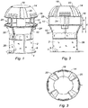
- the Figures 1, 2 and 3 have an air extraction fan intended to be placed on the roof or terrace of a building, comprising a lower cylinder 2 whose base is surrounded by a flat horizontal ring 4, receiving inside the passage of air extraction.
- gussets 6 distributed around the periphery of the lower cylinder 2, are fixed on the flat base ring 4 to frame fixing holes of this ring on the building, strengthening its connection with the cylinder.
- the assembly is made of steel sheets.
- a cap 14 placed above the exhaust fan has a basic circular contour having a diameter greater than that of the lower cylinder 2 to cover it, which is fixed above this cylinder leaving a vertical distance of total passage of Exit H.
- the cap 14 is connected to the lower cylinder 2 by four bars 28 distributed over the contour and arranged in two vertical planes intersecting along the axis, each of which comprises starting from the bottom a slightly inclined outwardly 10, then a length vertical 12.
- a circular ring of reduced section 8 connects the four bars 28 between them at the base of the vertical lengths 12, it is substantially at half height of the total output passage H.
- the cap 14 has a generally circular shape bulging outwards, delimited by a lower plane 16 and an upper plane 18 which are horizontal.
- the curved circular shape has four recesses 20 arranged in vertical planes, distributed around the periphery, each comprising at its base a horizontal plane having a bore 22 allowing screwing on a horizontal flat ring fixed at the top of the vertical lengths 12 of the webs 28.
- the cap 14 is formed by molding or thermoforming a plastic material, which makes it possible to directly obtain a finished product with complex shapes.
- the air extraction fan comprises inside an axial tube 24 made of sheet metal, of significantly reduced diameter relative to that of the lower cylinder 2 so as to allow the passage of the extraction flow between them.
- the inner tube 24 has an internally disposed electric motor, the end of the downwardly facing shaft receiving a turbine fitted into the lower cylinder 2 so as to generate the air extraction flow if necessary.
- the turbine has vanes having a very low pressure drop for the air flow at standstill, which makes it possible to leave the engine stopped when the natural draft is sufficient.
- the lower cylinder 2 extends above it in a manner adjusted by a flared circular flange 30, molded of plastics material, which comprises by mounting a gradually flared outwardly, so as to end slightly below the circular ring 8 connecting the bars 28 between them, with a substantially equivalent diameter.
- the figure 4 presents the exhaust fan without the flared shell 30, having a protective grid 50 which circumnavigates the normal exit passage, so as to protect this output of intrusions, leaves or birds for example.
- the Figures 5 and 6 have the flared shell 30 having at its base a small circular recess of constant height 32 allowing adjustment in the base cylinder 2, having holes 40 receiving twelve rivets distributed around the periphery and passing through the base cylinder, in order to ensure a secure fixation on its entire periphery.
- Flared shell 30 has at the bottom four notches 34, each allowing the passage of the base of a bar 28 which is fitted therein.
- the flared shell 30 comprises in the upper part a stiffening flange 36, comprising a horizontal part turned outwards then a vertical part turned upwards, also having four notches 38 each allowing the passage of a bar 28 which is fitted in. not to exceed outside this shell.
- the operation of the exhaust fan according to the invention is as follows. In normal operation, the turbine being stopped or running at a variable speed, the air flow is guided by the flared shell 30 to gradually climb outward through the normal flow section output of height H1, above this ferrule.
- the ventilation circuit then extracts air and fumes at a high temperature, which can reach in particular 400 ° C.
- a high temperature which can reach in particular 400 ° C.
- the fastening rivets of the lower contour of the flared shell 30 on the base cylinder 2 clamp the plastic material of this ferrule with wide washers, in order to ensure a circular maintenance of this contour on the cylinder, avoiding that it does not retract inward which would hinder the passage of gases.
- the plastic material of the flared shell a material having a low temperature, good mechanical and chemical resistance, in particular high rigidity, and which will easily flex with the temperature of the fumes, without producing an inflamed drop.
- the protective grid 50 may also be chosen from a fusible material, so as to bend and possibly melt to increase the passage section of the fumes in case of fire.
- the fan turbine is also selected from a plastic material that easily softens with the flue gas temperature, causing its retraction towards the axis and downwards so as to release the passage of the fumes by reducing the losses of loads caused by the turbine at a standstill.
- the fume extraction with the ventilation circuit is thus easily and economically promoted with these various measures even if the turbine no longer operates, which improves the safety of people and buildings.
- An example of well-adapted dimensions for a large variety of buildings includes a diameter of the base cylinder 2 of the exhaust fan of about 430mm, an outer diameter of the shell flared about 600mm, a height of the normal passage of exit H1 about 150mm, and a height of the additional H2 exit passage of about 140mm.
- the exhaust fan according to the invention is applied to a ventilation circuit with or without a motorized turbine.
Landscapes
- Engineering & Computer Science (AREA)
- Mechanical Engineering (AREA)
- General Engineering & Computer Science (AREA)
- Chemical & Material Sciences (AREA)
- Combustion & Propulsion (AREA)
- Physics & Mathematics (AREA)
- Geometry (AREA)
- Structures Of Non-Positive Displacement Pumps (AREA)
Abstract
Description
- La présente invention concerne un ventilateur d'extraction prévu pour renouveler l'air d'un bâtiment, en particulier pour une habitation ou un bâtiment tertiaire.
- Les bâtiments recevant des personnes, notamment les logements ou les locaux tertiaires comme les écoles ou les bureaux, comportent généralement un système d'aération des différentes pièces pour renouveler l'air, comprenant un système d'extraction de l'air des locaux, et des entrées d'air venant de l'extérieur afin de compenser cette extraction.
- Le renouvellement de l'air des pièces a pour principal objectif d'évacuer les polluants de l'air liés à la présence des occupants, à la présence du matériel ou des machines utilisées dans ces locaux, ainsi que ceux émis par le bâtiment lui-même.
- En particulier chaque personne respirant pendant une journée un volume d'air d'environ 12m3, il est important pour des raisons d'hygiène et de confort de réaliser un renouvellement de l'air des pièces fermées. On renouvelle aussi cet air pour contrôler le taux d'hygrométrie intérieur du bâtiment. De plus il est nécessaire de maîtriser le débit du renouvellement d'air, afin de limiter les déperditions thermiques dues à l'évacuation de l'air intérieur chauffé en hiver.
- La ventilation des locaux peut être naturelle, avec des conduits d'air partant de différentes pièces pour déboucher à l'extérieur, qui présentent un tirage thermique activé par la différence de pression naturelle quand l'air est plus froid à l'extérieur. Quand la température extérieure est plus élevée on perd le différentiel de pression entre l'intérieur et l'extérieur, et le débit d'air peut être insuffisant.
- La ventilation des locaux peut être aussi réalisée par une ventilation mécanique contrôlée appelée « VMC », comportant une turbine entraînée par un moteur électrique tournant en permanence, qui génère une dépression pour activer le débit dans les conduits d'air débouchant à l'extérieur.
- En variante un système de ventilation intermédiaire, appelé aussi ventilation hybride, comporte une turbine présentant à l'arrêt une faible perte de charge dans le conduit, qui est arrêtée quand le tirage thermique de la ventilation naturelle est suffisante, et qui tourne à une vitesse variable adaptée quand la ventilation naturelle et insuffisante pour compenser le débit trop faible. En particulier la vitesse de la turbine peut être ajustée automatiquement en fonction de la température extérieure qui active la ventilation naturelle.
- De cette manière on obtient toujours un débit d'air suffisant pendant toute l'année avec une turbine arrêtée autant que possible, et une vitesse croissante en fonction des besoins pour établir le débit nécessaire, ce qui réduit la consommation de courant électrique et les émissions sonores.
- Toutefois un problème se pose en cas d'incendie, la ventilation devant garantir un débit suffisant dans toutes les conditions, notamment en présence d'une turbine quand elle est à l'arrêt alors qu'elle freine ce débit par une restriction de la section de passage. Le classement au feu des ventilateurs d'extraction d'air doit être du type « C4 », qui impose un débit de ventilation suffisant pendant 30mn minimum alors que la température de l'air extrait est de 400°C.
- La présente invention propose à cet effet un ventilateur d'extraction d'air prévu pour être disposé sur un bâtiment en sortie d'un circuit de ventilation, présentant un passage normal pour la sortie de l'air vers l'extérieur, ce ventilateur étant remarquable en ce qu'il comporte une partie déformable fermant un passage vers l'extérieur, qui se déforme en température sous l'effet de gaz chauds dans le ventilateur lors d'un incendie, de manière à former un passage additionnel de sortie s'ajoutant au passage normal de sortie pour augmenter la section totale de passage vers l'extérieur.
- Un avantage de ce ventilateur d'extraction d'air et qu'en cas d'incendie dans le bâtiment, le passage de l'air ou des fumées à température plus élevée dans ce ventilateur s'accompagne d'un échauffement de la partie déformable, qui se déforme en augmentant alors automatiquement la section de passage des fumées vers l'extérieur et en réduisant la perte de charge du flux, ce qui améliore le débit. On peut en particulier compenser une perte de charge due à l'arrêt d'une turbine d'extraction, dans le cas où l'installation en comporte une.
- On facilite alors la sortie naturelle des gaz chauds dans le bâtiment vers l'extérieur.
- Le ventilateur d'extraction selon l'invention peut de plus comporter une ou plusieurs des caractéristiques suivantes, qui peuvent être combinées entre elles.
- Avantageusement, la partie déformable est disposée en-dessous du passage normal de sortie d'air.
- Dans ce cas, la partie déformable peut former une virole évasée qui s'ouvre vers l'extérieur en se rapprochant du passage normal de sortie d'air. On donne ainsi une forme aéraulique au conduit de sortie d'air vers l'extérieur.
- En particulier, le ventilateur d'extraction peut comporter successivement en partant du bas un cylindre de base, la virole évasée de la partie déformable qui se raccorde de manière ajustée sur ce cylindre, le passage normal de sortie d'air de forme cylindrique, et un chapeau couvrant ce passage.
- Avantageusement, la partie déformable comporte une matière plastique mise en forme par moulage ou thermoformage, ne produisant pas de goutte enflammée en cas d'incendie. On réalise ainsi simplement et de manière économique une forme complexe facilement déformable en température.
- En particulier, le ventilateur d'extraction peut comporter une turbine d'extraction d'air entraînée par un moteur. On forme ainsi un ensemble intégré comprenant un moyen de mise en dépression pour activer le flux d'air dans toutes les conditions atmosphériques.
- Avantageusement, la turbine d'extraction comporte un matériau plastique qui se ramollit et fléchit avec la température du débit des gaz chauds dans le ventilateur.
- Avantageusement, le passage normal de sortie comporte une grille de protection.
- Avantageusement, la section du passage additionnel de sortie du ventilateur est égale à au moins la section du passage normal de sortie.
- L'invention sera mieux comprise et d'autres caractéristiques et avantages apparaîtront plus clairement à la lecture de la description ci-après donnée à titre d'exemple, en référence aux dessins annexés dans lesquels :
- les
figures 1, 2 et 3 sont des vues respectivement en perspective, de côté et de dessus, d'un ventilateur d'extraction d'air selon l'invention comportant sa partie déformable, la grille de sortie étant démontée ; - la
figure 4 présente ce même ventilateur comportant sa grille de sortie, sa partie déformable étant démontée ; - la
figure 5 présente en perspective la partie déformable seule ; et - la
figure 6 est une vue de côté de la partie déformable, montrant sa déformation en température. - Les
figures 1, 2 et 3 présentent un ventilateur d'extraction d'air prévu pour être posé sur la toiture ou la terrasse d'un bâtiment, comportant un cylindre inférieur 2 dont la base est entourée par une couronne horizontale plate 4, recevant à l'intérieur le passage d'extraction d'air. - Quatre goussets 6 répartis sur le pourtour du cylindre inférieur 2, sont fixés sur la couronne plate de base 4 pour encadrer des perçages de fixation de cette couronne sur le bâtiment, en renforçant sa liaison avec le cylindre. L'ensemble est réalisé dans des tôles d'acier.
- Un chapeau 14 posé au-dessus du ventilateur d'extraction présente un contour circulaire de base comportant un diamètre supérieur à celui du cylindre inférieur 2 pour le recouvrir, qui est fixé au-dessus de ce cylindre en laissant une distance verticale de passage total de sortie H.
- Le chapeau 14 est relié au cylindre inférieur 2 par quatre barrettes 28 réparties sur le contour et disposées dans deux plans verticaux se croisant suivant l'axe, qui comportent chacune en partant du bas une longueur légèrement inclinée vers l'extérieur 10, puis une longueur verticale 12. Un anneau circulaire de section réduite 8 relie les quatre barrettes 28 entre elles au niveau de la base des longueurs verticales 12, il se trouve sensiblement à mi-hauteur du passage total de sortie H.
- Le chapeau 14 comporte une forme globalement circulaire bombée vers l'extérieur, délimitée par un plan inférieur 16 et un plan supérieur 18 qui sont horizontaux. La forme circulaire bombée présente quatre creux 20 disposés dans des plans verticaux, répartis sur le pourtour, comprenant chacun à sa base un plan horizontal présentant un perçage 22 permettant le vissage sur une couronne horizontale plate fixée en haut des longueurs verticales 12 des barrettes 28.
- Avantageusement le chapeau 14 est formé par le moulage ou le thermoformage d'une matière plastique, qui permet d'obtenir directement un produit fini avec des formes complexes.
- Le ventilateur d'extraction d'air comporte à l'intérieur un tube axial 24 réalisé en tôle métallique, de diamètre nettement réduit par rapport à celui du cylindre inférieur 2 de manière à laisser le passage du flux d'extraction entre eux.
- Le tube intérieur 24 comporte un moteur électrique disposé à l'intérieur, dont l'extrémité de l'arbre tourné vers le bas reçoit une turbine ajustée dans le cylindre inférieur 2 de manière à générer le flux d'extraction d'air si nécessaire. La turbine comporte des aubes présentant à l'arrêt une très faible perte de charge pour le flux d'air, ce qui permet de laisser le moteur arrêté quand le tirage naturel est suffisant.
- Un câble électrique 26 venant de l'extérieur monte à l'extérieur du cylindre inférieur 2, puis d'une barrette 28, pour arriver dans le chapeau 14 et alimenter le moteur électrique.
- Le cylindre inférieur 2 se prolonge au-dessus de manière ajustée par une collerette circulaire évasée 30, moulée en matière plastique, qui comporte en montant une forme progressivement évasée vers l'extérieur, de manière à se terminer légèrement en dessous de l'anneau circulaire 8 reliant les barrettes 28 entre elles, avec un diamètre sensiblement équivalent.
- Dans un fonctionnement normal l'air montant verticalement dans le ventilateur d'extraction entre le tube intérieur 24 et le cylindre de base 2, est progressivement guidé radialement vers l'extérieur par la collerette évasée 30, pour sortir radialement dans le passage normal de sortie de hauteur H1, formé entre cette collerette et le chapeau 14.
- La
figure 4 présente le ventilateur d'extraction sans la virole évasée 30, comportant une grille de protection 50 qui fait le tour du passage normal de sortie, de manière à protéger cette sortie d'intrusions, de feuilles ou d'oiseaux par exemple. - Les
figures 5 et 6 présentent la virole évasée 30 comportant à sa base un petit retrait circulaire de hauteur constante 32 permettant un ajustement dans le cylindre de base 2, présentant des perçages 40 recevant douze rivets de fixation répartis sur le pourtour et traversant ce cylindre de base, afin d'assurer une fixation solide sur son pourtour complet. La virole évasée 30 comporte en partie inférieure quatre échancrures 34, permettant chacune le passage de la base d'une barrette 28 qui est ajustée dedans. - La virole évasée 30 comporte en partie supérieure un rebord de rigidification 36, comprenant une partie horizontale tournée vers l'extérieur puis une partie verticale tournée vers le haut, présentant aussi quatre échancrures 38 permettant chacune le passage d'une barrette 28 qui est ajustée dedans pour ne pas dépasser à l'extérieur de cette virole.
- Le fonctionnement du ventilateur d'extraction d'air selon l'invention est le suivant. Dans un fonctionnement normal, la turbine étant à l'arrêt ou en marche à une vitesse variable, le débit d'air est guidé par la virole évasée 30 pour en montant progressivement partir vers l'extérieur au travers de la section de passage normal de sortie de hauteur H1, au-dessus de cette virole.
- En cas d'incendie dans le bâtiment, le circuit de ventilation extrait alors de l'air et des fumées à une température élevée, qui peut atteindre en particulier 400°C. En choisissant le matériau plastique de la virole évasée 30, on obtient sous l'effet de ces gaz chauds un échauffement et un ramollissement de ce matériau, qui tend à s'affaisser vers l'extérieur et vers le bas comme présenté par les flèches F de la
figure 6 , pour atteindre la position basse 42. - Avantageusement les rivets de fixation du contour inférieur de la virole évasée 30 sur le cylindre de base 2 serrent la matière plastique de cette virole par des rondelles larges, afin d'assurer un maintien circulaire de ce contour sur le cylindre, en évitant qu'il ne se rétracte vers l'intérieur ce qui gênerait le passage des gaz.
- On a alors le dégagement d'un passage additionnel de sortie des gaz chauds, qui peut présenter après une ouverture complète la hauteur additionnelle H2, s'additionnant à la hauteur H1 du passage normal de sortie pour donner la hauteur de passage total H. On obtient une perte de charge fortement diminuée pour cette sortie, qui peut compenser un arrêt de la turbine, particulièrement dans le cas où l'alimentation électrique du bâtiment est coupée.
- Avantageusement on choisit pour la matière plastique de la virole évasée 30 une matière comportant à basse température une bonne résistance mécanique et chimique, en particulier une rigidité élevée, et qui va facilement fléchir avec la température des fumées, sans produire de goutte enflammée.
- La grille de protection 50 peut aussi être choisie dans un matériau fusible, de manière à fléchir et éventuellement fondre pour augmenter la section de passage des fumées en cas d'incendie.
- De plus, avantageusement la turbine du ventilateur est aussi choisie dans un matériau plastique qui se ramollit facilement avec la température des fumées, en entraînant sa rétractation vers l'axe et vers le bas de manière à libérer le passage des fumées en diminuant les pertes de charges causées par la turbine à l'arrêt.
- On favorise ainsi de manière simple et économique avec ces différentes mesures, l'extraction des fumées avec le circuit de ventilation même si la turbine ne fonctionne plus, ce qui améliore la sécurité des personnes et des bâtiments.
- Un exemple de dimensions bien adaptées pour une grande variété de bâtiments comporte un diamètre du cylindre de base 2 du ventilateur d'extraction d'environ 430mm, un diamètre extérieur de la virole évasée d'environ 600mm, une hauteur du passage normal de sortie H1 d'environ 150mm, et une hauteur du passage additionnel de sortie H2 d'environ 140mm.
- On obtient alors une section du passage normal de sortie avec la grille 50 d'environ 2600cm2, qui est agrandie après disparation de la grille à environ 2900cm2, et après fléchissement de la collerette évasée 30 à environ 5300cm2. On note dans ce cas que la section du passage total de sortie a plus que doublé par rapport au passage normal.
- D'une manière générale, le ventilateur d'extraction selon l'invention s'applique sur un circuit de ventilation avec ou sans turbine motorisée.
Claims (9)
- Ventilateur d'extraction d'air prévu pour être disposé sur un bâtiment en sortie d'un circuit de ventilation, présentant un passage normal pour la sortie de l'air vers l'extérieur, caractérisé en ce qu'il comporte une partie déformable (30) fermant un passage vers l'extérieur, qui se déforme en température sous l'effet d'un débit de gaz chauds dans le ventilateur lors d'un incendie, de manière à former un passage additionnel de sortie s'ajoutant au passage normal de sortie pour augmenter la section totale de passage vers l'extérieur.
- Ventilateur d'extraction selon la revendication 1, caractérisé en ce que la partie déformable (30) est disposée en-dessous du passage normal de sortie d'air.
- Ventilateur d'extraction selon la revendication 2, caractérisé en ce que la partie déformable (30) forme une virole évasée qui s'ouvre vers l'extérieur en se rapprochant du passage normal de sortie d'air.
- Ventilateur d'extraction selon la revendication 3, caractérisé en ce qu'il comporte successivement en partant du bas un cylindre de base (2), la virole évasée de la partie déformable (30) qui se raccorde de manière ajustée sur ce cylindre, le passage normal de sortie d'air de forme cylindrique, et un chapeau couvrant ce passage (14).
- Ventilateur d'extraction selon l'une quelconque des revendications précédentes, caractérisé en ce que la partie déformable (30) comporte une matière plastique mise en forme par moulage ou thermoformage, ne produisant pas de goutte enflammée en cas d'incendie.
- Ventilateur d'extraction selon l'une quelconque des revendications précédentes, caractérisé en ce qu'il comporte une turbine d'extraction d'air entraînée par un moteur.
- Ventilateur d'extraction selon la revendication 6, caractérisé en ce que la turbine d'extraction comporte un matériau plastique qui se ramollit et fléchit avec la température du débit des gaz chauds dans le ventilateur.
- Ventilateur d'extraction selon l'une quelconque des revendications précédentes, caractérisé en ce que le passage normal de sortie comporte une grille de protection (50).
- Ventilateur d'extraction selon l'une quelconque des revendications précédentes, caractérisé en ce que la section du passage additionnel de sortie du ventilateur est égale à au moins la section du passage normal de sortie.
Applications Claiming Priority (1)
| Application Number | Priority Date | Filing Date | Title |
|---|---|---|---|
| FR1653786A FR3050808B1 (fr) | 2016-04-28 | 2016-04-28 | Ventilateur d'extraction d'air a section de passage variable en cas d'incendie |
Publications (2)
| Publication Number | Publication Date |
|---|---|
| EP3239620A1 true EP3239620A1 (fr) | 2017-11-01 |
| EP3239620B1 EP3239620B1 (fr) | 2020-09-02 |
Family
ID=56511715
Family Applications (1)
| Application Number | Title | Priority Date | Filing Date |
|---|---|---|---|
| EP17168460.8A Active EP3239620B1 (fr) | 2016-04-28 | 2017-04-27 | Ventilateur d'extraction d'air à section de passage variable en cas d'incendie |
Country Status (4)
| Country | Link |
|---|---|
| EP (1) | EP3239620B1 (fr) |
| FR (1) | FR3050808B1 (fr) |
| HU (1) | HUE051621T2 (fr) |
| RU (1) | RU2734377C2 (fr) |
Cited By (2)
| Publication number | Priority date | Publication date | Assignee | Title |
|---|---|---|---|---|
| CN111294729A (zh) * | 2018-12-07 | 2020-06-16 | 中国移动通信集团终端有限公司 | 移动终端的网络切换方法、装置、设备及介质 |
| CN114234324A (zh) * | 2021-12-24 | 2022-03-25 | 西华大学 | 一种绿色建筑用通风节能设备 |
Citations (4)
| Publication number | Priority date | Publication date | Assignee | Title |
|---|---|---|---|---|
| EP0055665A1 (fr) * | 1980-12-31 | 1982-07-07 | JEUMONT-SCHNEIDER Société anonyme dite: | Procédé pour soustraire aux contraintes thermiques accidentelles un moteur de ventilateur aérateur capable d'évacuer des fumées chaudes en cas d'incendie et dispositif pour la mise en oeuvre de ce procédé |
| DE29917485U1 (de) * | 1999-10-04 | 1999-12-09 | Gebrüder Trox, GmbH, 47506 Neukirchen-Vluyn | Rauch- und Wärmeabzugsanlage |
| US20140199938A1 (en) * | 2013-01-15 | 2014-07-17 | Fusion Hvac Pty Limited | Apparatus for exhausting air |
| FR3021099A1 (fr) * | 2014-05-13 | 2015-11-20 | Soler & Palau Res Sl | Caisson de ventilation |
Family Cites Families (1)
| Publication number | Priority date | Publication date | Assignee | Title |
|---|---|---|---|---|
| RU136542U1 (ru) * | 2013-09-06 | 2014-01-10 | Рустам Кимович Эсманский | Крышная вытяжная вентиляторная установка |
-
2016
- 2016-04-28 FR FR1653786A patent/FR3050808B1/fr not_active Expired - Fee Related
-
2017
- 2017-04-27 RU RU2017115058A patent/RU2734377C2/ru active
- 2017-04-27 HU HUE17168460A patent/HUE051621T2/hu unknown
- 2017-04-27 EP EP17168460.8A patent/EP3239620B1/fr active Active
Patent Citations (4)
| Publication number | Priority date | Publication date | Assignee | Title |
|---|---|---|---|---|
| EP0055665A1 (fr) * | 1980-12-31 | 1982-07-07 | JEUMONT-SCHNEIDER Société anonyme dite: | Procédé pour soustraire aux contraintes thermiques accidentelles un moteur de ventilateur aérateur capable d'évacuer des fumées chaudes en cas d'incendie et dispositif pour la mise en oeuvre de ce procédé |
| DE29917485U1 (de) * | 1999-10-04 | 1999-12-09 | Gebrüder Trox, GmbH, 47506 Neukirchen-Vluyn | Rauch- und Wärmeabzugsanlage |
| US20140199938A1 (en) * | 2013-01-15 | 2014-07-17 | Fusion Hvac Pty Limited | Apparatus for exhausting air |
| FR3021099A1 (fr) * | 2014-05-13 | 2015-11-20 | Soler & Palau Res Sl | Caisson de ventilation |
Cited By (2)
| Publication number | Priority date | Publication date | Assignee | Title |
|---|---|---|---|---|
| CN111294729A (zh) * | 2018-12-07 | 2020-06-16 | 中国移动通信集团终端有限公司 | 移动终端的网络切换方法、装置、设备及介质 |
| CN114234324A (zh) * | 2021-12-24 | 2022-03-25 | 西华大学 | 一种绿色建筑用通风节能设备 |
Also Published As
| Publication number | Publication date |
|---|---|
| HUE051621T2 (hu) | 2021-03-01 |
| EP3239620B1 (fr) | 2020-09-02 |
| RU2017115058A (ru) | 2018-10-29 |
| RU2734377C2 (ru) | 2020-10-15 |
| RU2017115058A3 (fr) | 2020-06-05 |
| FR3050808B1 (fr) | 2018-06-01 |
| FR3050808A1 (fr) | 2017-11-03 |
Similar Documents
| Publication | Publication Date | Title |
|---|---|---|
| US9284945B2 (en) | Wind turbine and tower system | |
| EP3239620B1 (fr) | Ventilateur d'extraction d'air à section de passage variable en cas d'incendie | |
| EP0204611A2 (fr) | Dispositif d'aération des locaux et de tirage des cheminées | |
| FR2658593A1 (fr) | Bouche d'entree d'air. | |
| ITUD940178A1 (it) | Perfezionamenti ai dispositivi modulari permettenti l'assemblaggio di apparecchiature per l'estrazione dei fumi o l'aerazione dei | |
| US8240977B2 (en) | Wind collector device for generation of energy | |
| US20180045417A1 (en) | Double wall fire pit | |
| EP1947384B1 (fr) | Dispositif d'assistance mécanique pour l'évacuation de flux gazeux plus particulièrement destiné à un ensemble habitable | |
| FR2626324A1 (fr) | Procede de mise en mouvement de l'air dans une gaine d'aeration par jets d'air induits et son extension pour d'autres fluides | |
| KR102170270B1 (ko) | 화재에 대비한 송풍기 조립체 | |
| US544390A (en) | Chimney-cowl | |
| US1254517A (en) | Ventilator. | |
| FR2848616A1 (fr) | Perfectionnements pour dispositifs capteurs d'energie eolienne | |
| BE1018575A3 (fr) | Rideau d'air a recuperation de calories. | |
| BE1024272B1 (fr) | Rideau d'air a recuperation de calories | |
| BE1026869A1 (fr) | Turbine aerolique a flux traversant | |
| JP5325258B2 (ja) | 薪ストーブ | |
| FR2587458A2 (fr) | Dispositif d'aeration des locaux et de tirage des cheminees | |
| KR102312705B1 (ko) | 배기성능이 향상된 동력 고정식 벤틸레이터 | |
| FR2891474A1 (fr) | Dispositif de brumisation | |
| FR3051517A1 (fr) | Extracteur de gaz comprenant une eolienne, un ventilateur, un moteur et un dispositif d'accouplement | |
| FR2982011A1 (fr) | Dispositif de recuperation de chaleur pour un poele, notamment un poele a bois, ainsi qu'installation correspondante de chauffage d'un batiment | |
| EP1634020A1 (fr) | Dispositif pour augmenter le tirage dans des cheminees | |
| FR3048759B1 (fr) | Systemes d'entree d'air pour un batiment comportant une entretoise donnant un flux constant | |
| FR2776054A1 (fr) | Installation de ventilation collective a prise d'air a ouverture thermique |
Legal Events
| Date | Code | Title | Description |
|---|---|---|---|
| PUAI | Public reference made under article 153(3) epc to a published international application that has entered the european phase |
Free format text: ORIGINAL CODE: 0009012 |
|
| STAA | Information on the status of an ep patent application or granted ep patent |
Free format text: STATUS: THE APPLICATION HAS BEEN PUBLISHED |
|
| AK | Designated contracting states |
Kind code of ref document: A1 Designated state(s): AL AT BE BG CH CY CZ DE DK EE ES FI FR GB GR HR HU IE IS IT LI LT LU LV MC MK MT NL NO PL PT RO RS SE SI SK SM TR |
|
| AX | Request for extension of the european patent |
Extension state: BA ME |
|
| STAA | Information on the status of an ep patent application or granted ep patent |
Free format text: STATUS: REQUEST FOR EXAMINATION WAS MADE |
|
| 17P | Request for examination filed |
Effective date: 20180430 |
|
| RBV | Designated contracting states (corrected) |
Designated state(s): AL AT BE BG CH CY CZ DE DK EE ES FI FR GB GR HR HU IE IS IT LI LT LU LV MC MK MT NL NO PL PT RO RS SE SI SK SM TR |
|
| RIC1 | Information provided on ipc code assigned before grant |
Ipc: F24F 11/00 20180101ALI20200408BHEP Ipc: F24F 7/02 20060101AFI20200408BHEP |
|
| GRAP | Despatch of communication of intention to grant a patent |
Free format text: ORIGINAL CODE: EPIDOSNIGR1 |
|
| STAA | Information on the status of an ep patent application or granted ep patent |
Free format text: STATUS: GRANT OF PATENT IS INTENDED |
|
| INTG | Intention to grant announced |
Effective date: 20200515 |
|
| GRAS | Grant fee paid |
Free format text: ORIGINAL CODE: EPIDOSNIGR3 |
|
| GRAA | (expected) grant |
Free format text: ORIGINAL CODE: 0009210 |
|
| STAA | Information on the status of an ep patent application or granted ep patent |
Free format text: STATUS: THE PATENT HAS BEEN GRANTED |
|
| RAP1 | Party data changed (applicant data changed or rights of an application transferred) |
Owner name: AERECO |
|
| AK | Designated contracting states |
Kind code of ref document: B1 Designated state(s): AL AT BE BG CH CY CZ DE DK EE ES FI FR GB GR HR HU IE IS IT LI LT LU LV MC MK MT NL NO PL PT RO RS SE SI SK SM TR |
|
| REG | Reference to a national code |
Ref country code: GB Ref legal event code: FG4D Free format text: NOT ENGLISH |
|
| REG | Reference to a national code |
Ref country code: AT Ref legal event code: REF Ref document number: 1309284 Country of ref document: AT Kind code of ref document: T Effective date: 20200915 Ref country code: CH Ref legal event code: EP |
|
| REG | Reference to a national code |
Ref country code: DE Ref legal event code: R096 Ref document number: 602017022618 Country of ref document: DE |
|
| REG | Reference to a national code |
Ref country code: IE Ref legal event code: FG4D Free format text: LANGUAGE OF EP DOCUMENT: FRENCH |
|
| REG | Reference to a national code |
Ref country code: CH Ref legal event code: NV Representative=s name: CABINET GERMAIN AND MAUREAU, CH |
|
| REG | Reference to a national code |
Ref country code: SE Ref legal event code: TRGR |
|
| REG | Reference to a national code |
Ref country code: LT Ref legal event code: MG4D |
|
| PG25 | Lapsed in a contracting state [announced via postgrant information from national office to epo] |
Ref country code: FI Free format text: LAPSE BECAUSE OF FAILURE TO SUBMIT A TRANSLATION OF THE DESCRIPTION OR TO PAY THE FEE WITHIN THE PRESCRIBED TIME-LIMIT Effective date: 20200902 Ref country code: BG Free format text: LAPSE BECAUSE OF FAILURE TO SUBMIT A TRANSLATION OF THE DESCRIPTION OR TO PAY THE FEE WITHIN THE PRESCRIBED TIME-LIMIT Effective date: 20201202 Ref country code: GR Free format text: LAPSE BECAUSE OF FAILURE TO SUBMIT A TRANSLATION OF THE DESCRIPTION OR TO PAY THE FEE WITHIN THE PRESCRIBED TIME-LIMIT Effective date: 20201203 Ref country code: NO Free format text: LAPSE BECAUSE OF FAILURE TO SUBMIT A TRANSLATION OF THE DESCRIPTION OR TO PAY THE FEE WITHIN THE PRESCRIBED TIME-LIMIT Effective date: 20201202 Ref country code: HR Free format text: LAPSE BECAUSE OF FAILURE TO SUBMIT A TRANSLATION OF THE DESCRIPTION OR TO PAY THE FEE WITHIN THE PRESCRIBED TIME-LIMIT Effective date: 20200902 Ref country code: LT Free format text: LAPSE BECAUSE OF FAILURE TO SUBMIT A TRANSLATION OF THE DESCRIPTION OR TO PAY THE FEE WITHIN THE PRESCRIBED TIME-LIMIT Effective date: 20200902 |
|
| REG | Reference to a national code |
Ref country code: NL Ref legal event code: MP Effective date: 20200902 |
|
| REG | Reference to a national code |
Ref country code: AT Ref legal event code: MK05 Ref document number: 1309284 Country of ref document: AT Kind code of ref document: T Effective date: 20200902 |
|
| PG25 | Lapsed in a contracting state [announced via postgrant information from national office to epo] |
Ref country code: LV Free format text: LAPSE BECAUSE OF FAILURE TO SUBMIT A TRANSLATION OF THE DESCRIPTION OR TO PAY THE FEE WITHIN THE PRESCRIBED TIME-LIMIT Effective date: 20200902 Ref country code: RS Free format text: LAPSE BECAUSE OF FAILURE TO SUBMIT A TRANSLATION OF THE DESCRIPTION OR TO PAY THE FEE WITHIN THE PRESCRIBED TIME-LIMIT Effective date: 20200902 |
|
| REG | Reference to a national code |
Ref country code: HU Ref legal event code: AG4A Ref document number: E051621 Country of ref document: HU |
|
| PG25 | Lapsed in a contracting state [announced via postgrant information from national office to epo] |
Ref country code: EE Free format text: LAPSE BECAUSE OF FAILURE TO SUBMIT A TRANSLATION OF THE DESCRIPTION OR TO PAY THE FEE WITHIN THE PRESCRIBED TIME-LIMIT Effective date: 20200902 Ref country code: RO Free format text: LAPSE BECAUSE OF FAILURE TO SUBMIT A TRANSLATION OF THE DESCRIPTION OR TO PAY THE FEE WITHIN THE PRESCRIBED TIME-LIMIT Effective date: 20200902 Ref country code: PT Free format text: LAPSE BECAUSE OF FAILURE TO SUBMIT A TRANSLATION OF THE DESCRIPTION OR TO PAY THE FEE WITHIN THE PRESCRIBED TIME-LIMIT Effective date: 20210104 Ref country code: CZ Free format text: LAPSE BECAUSE OF FAILURE TO SUBMIT A TRANSLATION OF THE DESCRIPTION OR TO PAY THE FEE WITHIN THE PRESCRIBED TIME-LIMIT Effective date: 20200902 Ref country code: SM Free format text: LAPSE BECAUSE OF FAILURE TO SUBMIT A TRANSLATION OF THE DESCRIPTION OR TO PAY THE FEE WITHIN THE PRESCRIBED TIME-LIMIT Effective date: 20200902 |
|
| PG25 | Lapsed in a contracting state [announced via postgrant information from national office to epo] |
Ref country code: ES Free format text: LAPSE BECAUSE OF FAILURE TO SUBMIT A TRANSLATION OF THE DESCRIPTION OR TO PAY THE FEE WITHIN THE PRESCRIBED TIME-LIMIT Effective date: 20200902 Ref country code: AL Free format text: LAPSE BECAUSE OF FAILURE TO SUBMIT A TRANSLATION OF THE DESCRIPTION OR TO PAY THE FEE WITHIN THE PRESCRIBED TIME-LIMIT Effective date: 20200902 Ref country code: AT Free format text: LAPSE BECAUSE OF FAILURE TO SUBMIT A TRANSLATION OF THE DESCRIPTION OR TO PAY THE FEE WITHIN THE PRESCRIBED TIME-LIMIT Effective date: 20200902 Ref country code: IS Free format text: LAPSE BECAUSE OF FAILURE TO SUBMIT A TRANSLATION OF THE DESCRIPTION OR TO PAY THE FEE WITHIN THE PRESCRIBED TIME-LIMIT Effective date: 20210102 |
|
| REG | Reference to a national code |
Ref country code: DE Ref legal event code: R097 Ref document number: 602017022618 Country of ref document: DE |
|
| PG25 | Lapsed in a contracting state [announced via postgrant information from national office to epo] |
Ref country code: SK Free format text: LAPSE BECAUSE OF FAILURE TO SUBMIT A TRANSLATION OF THE DESCRIPTION OR TO PAY THE FEE WITHIN THE PRESCRIBED TIME-LIMIT Effective date: 20200902 |
|
| PLBE | No opposition filed within time limit |
Free format text: ORIGINAL CODE: 0009261 |
|
| STAA | Information on the status of an ep patent application or granted ep patent |
Free format text: STATUS: NO OPPOSITION FILED WITHIN TIME LIMIT |
|
| 26N | No opposition filed |
Effective date: 20210603 |
|
| PG25 | Lapsed in a contracting state [announced via postgrant information from national office to epo] |
Ref country code: SI Free format text: LAPSE BECAUSE OF FAILURE TO SUBMIT A TRANSLATION OF THE DESCRIPTION OR TO PAY THE FEE WITHIN THE PRESCRIBED TIME-LIMIT Effective date: 20200902 Ref country code: DK Free format text: LAPSE BECAUSE OF FAILURE TO SUBMIT A TRANSLATION OF THE DESCRIPTION OR TO PAY THE FEE WITHIN THE PRESCRIBED TIME-LIMIT Effective date: 20200902 |
|
| PG25 | Lapsed in a contracting state [announced via postgrant information from national office to epo] |
Ref country code: IT Free format text: LAPSE BECAUSE OF FAILURE TO SUBMIT A TRANSLATION OF THE DESCRIPTION OR TO PAY THE FEE WITHIN THE PRESCRIBED TIME-LIMIT Effective date: 20200902 |
|
| PG25 | Lapsed in a contracting state [announced via postgrant information from national office to epo] |
Ref country code: MC Free format text: LAPSE BECAUSE OF FAILURE TO SUBMIT A TRANSLATION OF THE DESCRIPTION OR TO PAY THE FEE WITHIN THE PRESCRIBED TIME-LIMIT Effective date: 20200902 |
|
| PG25 | Lapsed in a contracting state [announced via postgrant information from national office to epo] |
Ref country code: LU Free format text: LAPSE BECAUSE OF NON-PAYMENT OF DUE FEES Effective date: 20210427 |
|
| REG | Reference to a national code |
Ref country code: BE Ref legal event code: MM Effective date: 20210430 |
|
| PG25 | Lapsed in a contracting state [announced via postgrant information from national office to epo] |
Ref country code: IS Free format text: LAPSE BECAUSE OF FAILURE TO SUBMIT A TRANSLATION OF THE DESCRIPTION OR TO PAY THE FEE WITHIN THE PRESCRIBED TIME-LIMIT Effective date: 20210102 |
|
| PG25 | Lapsed in a contracting state [announced via postgrant information from national office to epo] |
Ref country code: BE Free format text: LAPSE BECAUSE OF NON-PAYMENT OF DUE FEES Effective date: 20210430 |
|
| PG25 | Lapsed in a contracting state [announced via postgrant information from national office to epo] |
Ref country code: NL Free format text: LAPSE BECAUSE OF NON-PAYMENT OF DUE FEES Effective date: 20200923 Ref country code: CY Free format text: LAPSE BECAUSE OF FAILURE TO SUBMIT A TRANSLATION OF THE DESCRIPTION OR TO PAY THE FEE WITHIN THE PRESCRIBED TIME-LIMIT Effective date: 20200902 |
|
| P01 | Opt-out of the competence of the unified patent court (upc) registered |
Effective date: 20230526 |
|
| PG25 | Lapsed in a contracting state [announced via postgrant information from national office to epo] |
Ref country code: MK Free format text: LAPSE BECAUSE OF FAILURE TO SUBMIT A TRANSLATION OF THE DESCRIPTION OR TO PAY THE FEE WITHIN THE PRESCRIBED TIME-LIMIT Effective date: 20200902 |
|
| PGFP | Annual fee paid to national office [announced via postgrant information from national office to epo] |
Ref country code: GB Payment date: 20240328 Year of fee payment: 8 |
|
| PG25 | Lapsed in a contracting state [announced via postgrant information from national office to epo] |
Ref country code: TR Free format text: LAPSE BECAUSE OF FAILURE TO SUBMIT A TRANSLATION OF THE DESCRIPTION OR TO PAY THE FEE WITHIN THE PRESCRIBED TIME-LIMIT Effective date: 20200902 |
|
| PGFP | Annual fee paid to national office [announced via postgrant information from national office to epo] |
Ref country code: IE Payment date: 20240422 Year of fee payment: 8 |
|
| PGFP | Annual fee paid to national office [announced via postgrant information from national office to epo] |
Ref country code: DE Payment date: 20240415 Year of fee payment: 8 |
|
| PGFP | Annual fee paid to national office [announced via postgrant information from national office to epo] |
Ref country code: CH Payment date: 20240501 Year of fee payment: 8 |
|
| PGFP | Annual fee paid to national office [announced via postgrant information from national office to epo] |
Ref country code: SE Payment date: 20240423 Year of fee payment: 8 Ref country code: HU Payment date: 20240424 Year of fee payment: 8 |
|
| PG25 | Lapsed in a contracting state [announced via postgrant information from national office to epo] |
Ref country code: MT Free format text: LAPSE BECAUSE OF FAILURE TO SUBMIT A TRANSLATION OF THE DESCRIPTION OR TO PAY THE FEE WITHIN THE PRESCRIBED TIME-LIMIT Effective date: 20200902 |
|
| PGFP | Annual fee paid to national office [announced via postgrant information from national office to epo] |
Ref country code: PL Payment date: 20250409 Year of fee payment: 9 |
|
| REG | Reference to a national code |
Ref country code: DE Ref legal event code: R119 Ref document number: 602017022618 Country of ref document: DE |
|
| REG | Reference to a national code |
Ref country code: CH Ref legal event code: H13 Free format text: ST27 STATUS EVENT CODE: U-0-0-H10-H13 (AS PROVIDED BY THE NATIONAL OFFICE) Effective date: 20251125 |
|
| REG | Reference to a national code |
Ref country code: SE Ref legal event code: EUG |
|
| PG25 | Lapsed in a contracting state [announced via postgrant information from national office to epo] |
Ref country code: HU Free format text: LAPSE BECAUSE OF NON-PAYMENT OF DUE FEES Effective date: 20250428 |
|
| GBPC | Gb: european patent ceased through non-payment of renewal fee |
Effective date: 20250427 |
|
| PG25 | Lapsed in a contracting state [announced via postgrant information from national office to epo] |
Ref country code: DE Free format text: LAPSE BECAUSE OF NON-PAYMENT OF DUE FEES Effective date: 20251104 |
|
| PG25 | Lapsed in a contracting state [announced via postgrant information from national office to epo] |
Ref country code: GB Free format text: LAPSE BECAUSE OF NON-PAYMENT OF DUE FEES Effective date: 20250427 |
|
| PG25 | Lapsed in a contracting state [announced via postgrant information from national office to epo] |
Ref country code: CH Free format text: LAPSE BECAUSE OF NON-PAYMENT OF DUE FEES Effective date: 20250430 |
|
| PG25 | Lapsed in a contracting state [announced via postgrant information from national office to epo] |
Ref country code: SE Free format text: LAPSE BECAUSE OF NON-PAYMENT OF DUE FEES Effective date: 20250428 |
|
| PG25 | Lapsed in a contracting state [announced via postgrant information from national office to epo] |
Ref country code: IE Free format text: LAPSE BECAUSE OF NON-PAYMENT OF DUE FEES Effective date: 20250427 |
|
| PGFP | Annual fee paid to national office [announced via postgrant information from national office to epo] |
Ref country code: FR Payment date: 20260330 Year of fee payment: 10 |