EP3239675A1 - Appareil pour corriger le signal de mesure de température - Google Patents
Appareil pour corriger le signal de mesure de température Download PDFInfo
- Publication number
- EP3239675A1 EP3239675A1 EP16193107.6A EP16193107A EP3239675A1 EP 3239675 A1 EP3239675 A1 EP 3239675A1 EP 16193107 A EP16193107 A EP 16193107A EP 3239675 A1 EP3239675 A1 EP 3239675A1
- Authority
- EP
- European Patent Office
- Prior art keywords
- temperature sensing
- voltage
- sensing signal
- output limiting
- limiting diode
- Prior art date
- Legal status (The legal status is an assumption and is not a legal conclusion. Google has not performed a legal analysis and makes no representation as to the accuracy of the status listed.)
- Ceased
Links
Images



Classifications
-
- G—PHYSICS
- G01—MEASURING; TESTING
- G01K—MEASURING TEMPERATURE; MEASURING QUANTITY OF HEAT; THERMALLY-SENSITIVE ELEMENTS NOT OTHERWISE PROVIDED FOR
- G01K15/00—Testing or calibrating of thermometers
- G01K15/005—Calibration
-
- G—PHYSICS
- G01—MEASURING; TESTING
- G01K—MEASURING TEMPERATURE; MEASURING QUANTITY OF HEAT; THERMALLY-SENSITIVE ELEMENTS NOT OTHERWISE PROVIDED FOR
- G01K7/00—Measuring temperature based on the use of electric or magnetic elements directly sensitive to heat ; Power supply therefor, e.g. using thermoelectric elements
- G01K7/16—Measuring temperature based on the use of electric or magnetic elements directly sensitive to heat ; Power supply therefor, e.g. using thermoelectric elements using resistive elements
- G01K7/22—Measuring temperature based on the use of electric or magnetic elements directly sensitive to heat ; Power supply therefor, e.g. using thermoelectric elements using resistive elements the element being a non-linear resistance, e.g. thermistor
-
- H—ELECTRICITY
- H03—ELECTRONIC CIRCUITRY
- H03K—PULSE TECHNIQUE
- H03K17/00—Electronic switching or gating, i.e. not by contact-making and –breaking
- H03K17/08—Modifications for protecting switching circuit against overcurrent or overvoltage
- H03K17/082—Modifications for protecting switching circuit against overcurrent or overvoltage by feedback from the output to the control circuit
- H03K17/0828—Modifications for protecting switching circuit against overcurrent or overvoltage by feedback from the output to the control circuit in composite switches
-
- G—PHYSICS
- G01—MEASURING; TESTING
- G01K—MEASURING TEMPERATURE; MEASURING QUANTITY OF HEAT; THERMALLY-SENSITIVE ELEMENTS NOT OTHERWISE PROVIDED FOR
- G01K7/00—Measuring temperature based on the use of electric or magnetic elements directly sensitive to heat ; Power supply therefor, e.g. using thermoelectric elements
- G01K7/01—Measuring temperature based on the use of electric or magnetic elements directly sensitive to heat ; Power supply therefor, e.g. using thermoelectric elements using semiconducting elements having PN junctions
-
- G—PHYSICS
- G01—MEASURING; TESTING
- G01K—MEASURING TEMPERATURE; MEASURING QUANTITY OF HEAT; THERMALLY-SENSITIVE ELEMENTS NOT OTHERWISE PROVIDED FOR
- G01K7/00—Measuring temperature based on the use of electric or magnetic elements directly sensitive to heat ; Power supply therefor, e.g. using thermoelectric elements
- G01K7/16—Measuring temperature based on the use of electric or magnetic elements directly sensitive to heat ; Power supply therefor, e.g. using thermoelectric elements using resistive elements
- G01K7/22—Measuring temperature based on the use of electric or magnetic elements directly sensitive to heat ; Power supply therefor, e.g. using thermoelectric elements using resistive elements the element being a non-linear resistance, e.g. thermistor
- G01K7/24—Measuring temperature based on the use of electric or magnetic elements directly sensitive to heat ; Power supply therefor, e.g. using thermoelectric elements using resistive elements the element being a non-linear resistance, e.g. thermistor in a specially-adapted circuit, e.g. bridge circuit
- G01K7/25—Measuring temperature based on the use of electric or magnetic elements directly sensitive to heat ; Power supply therefor, e.g. using thermoelectric elements using resistive elements the element being a non-linear resistance, e.g. thermistor in a specially-adapted circuit, e.g. bridge circuit for modifying the output characteristic, e.g. linearising
-
- G—PHYSICS
- G06—COMPUTING OR CALCULATING; COUNTING
- G06F—ELECTRIC DIGITAL DATA PROCESSING
- G06F17/00—Digital computing or data processing equipment or methods, specially adapted for specific functions
- G06F17/10—Complex mathematical operations
-
- H—ELECTRICITY
- H03—ELECTRONIC CIRCUITRY
- H03K—PULSE TECHNIQUE
- H03K17/00—Electronic switching or gating, i.e. not by contact-making and –breaking
- H03K17/08—Modifications for protecting switching circuit against overcurrent or overvoltage
- H03K2017/0806—Modifications for protecting switching circuit against overcurrent or overvoltage against excessive temperature
-
- H—ELECTRICITY
- H03—ELECTRONIC CIRCUITRY
- H03K—PULSE TECHNIQUE
- H03K2217/00—Indexing scheme related to electronic switching or gating, i.e. not by contact-making or -breaking covered by H03K17/00
- H03K2217/0027—Measuring means of, e.g. currents through or voltages across the switch
Definitions
- the present invention relates to an apparatus for correcting a temperature sensing (or measurement) signal and more particularly, to an apparatus for correcting a temperature sensing signal, which is capable of determining a value of voltage drop generated in an output limiting diode included in an Insulated Gate Bipolar Transistor (IGBT) temperature sensor by calculating a value of a current flowing through the output limiting diode and capable of correcting an error of a temperature sensing signal output from the IGBT temperature sensor, which is caused by the voltage drop of the output limiting diode, by increasing a voltage of the temperature sensing signal by the voltage drop value.
- IGBT Insulated Gate Bipolar Transistor
- an Insulated Gate Bipolar Transistor refers to a high power switching transistor having a fast switching function to block or conduct a flow of electricity.
- the switching function requires a dedicated part having a high operation speed and a low power loss for a product requiring a precise operation, although it may be implemented with other parts or circuits.
- an existing switching semiconductor transistor has a demerit that it has a complicated circuit configuration and a low operation speed although it is inexpensive.
- an existing switching Metal Oxide Semiconductor Field Effect Transistor (MOSFET) has a demerit that it is expensive although it consumes low power and has a high operation speed.
- IGBT is evaluated as a product having only the merits of the above-mentioned transistor and MOSFET. Accordingly, the IGBT is being used as a switching device in a variety of power converters such as an inverter, a converter and so on. In typical, an IGBT for converting power of a high voltage and a large current generates hot heat due to resistance, which has an effect on stability and power efficiency of a power converter.
- the IGBT is provided with an IGBT temperature sensing device for measuring (or sensing) a temperature of the IGBT by using a Negative Temperature Coefficient (NTC) thermistor.
- NTC Negative Temperature Coefficient
- the NTC thermistor is a thermistor whose electrical resistance is continuously changed with a negative temperature coefficient, and is used as a temperature sensor using this characteristic.
- Fig. 1 is a circuit diagram of a conventional IGBT temperature sensing device.
- a conventional IGBT temperature sensor 10 includes a temperature sensor 11, a signal selector 12 and an AD input part 13.
- An NTC thermistor R NTC of the temperature sensor 11 is changed in its resistance with a change in temperature of the IGBT.
- a first voltage distributing resistor R 1 and a second voltage distributing resistor R 2 of the temperature sensor 11 distribute a voltage of a driving power supply V cc to the NTC thermistor R NTC according to a preset ratio.
- a temperature sensing signal is output to an output limiting diode D 1 according to the change in resistance of the NTC thermistor R NTC .
- the output limiting diode D 1 outputs the temperature sensing signal to the signal selector 12 only when a voltage of the temperature sensing signal is equal to or higher than a preset voltage.
- the signal selector 12 compares a voltage of a previously received temperature sensing signal with a voltage of a recently received temperature sensing signal. If the voltage of the recently received temperature sensing signal is higher than the voltage of the previously received temperature sensing signal, the signal selector 12 outputs the recently received temperature sensing signal to the AD input part 13.
- the AD input part 13 converts an analog voltage value of the temperature sensing signal to a digital voltage value which is then output to the outside or an IGBT controller.
- the conventional IGBT temperature sensor 10 uses the output limiting diode D 1 conducted only when a driving voltage is applied to output only a temperature sensing signal having a voltage equal to or higher than the preset voltage value.
- IGBT Insulated Gate Bipolar Transistor
- an apparatus for correcting a temperature sensing signal of an IGBT temperature sensing device which outputs only a temperature sensing signal having a voltage value equal to or higher than a preset voltage value, by using an output limiting diode, including: a calculating part configured to calculate a conduction current value of the output limiting diode by using the resistance of an NTC thermistor included in the IGBT temperature sensing device; a determining part configured to determine a drop voltage value of a voltage drop occurring in the output limiting diode based on the conduction current value; and a correcting part configured to correct the temperature sensing signal by increasing the voltage of the temperature sensing signal output from the IGBT temperature sensing device by the drop voltage value.
- the present invention it is possible to measure the IGBT temperature with precision by determining a value of voltage drop generated in an output limiting diode included in an IGBT temperature sensor by calculating a value of a current flowing through the output limiting diode, and correcting an error of a temperature sensing signal output from the IGBT temperature sensor, which is caused by the voltage drop of the output limiting diode, by increasing a voltage of the temperature sensing signal by the voltage drop value.
- Fig. 2 is a block diagram illustrating an IGBT temperature sensing device 200 provided with a temperature sensing signal corrector 100 according to one embodiment of the present invention.
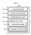
- Fig. 3 is a schematic view illustrating the detailed configuration of the temperature sensing signal corrector 100 according to one embodiment of the present invention.
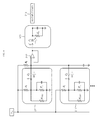
- Fig. 4 is a circuit diagram of the temperature sensing signal corrector 100 and the IGBT temperature sensing device 200 according to one embodiment of the present invention.
- the IGBT temperature sensing device 200 provided with the temperature sensing signal corrector 100 includes a plurality of temperature sensors 211, a signal selector 212 and an AD input part 213.
- An NTC thermistor R NTC of each temperature sensor 211 is installed in the IGBT and is changed in its resistance with a change in temperature of the IGBT. At this time, a first voltage distributing resistor R 1 and a second voltage distributing resistor R 2 of the temperature sensor 211 distribute a voltage of a driving power supply V cc to the NTC thermistor R NTC according to a preset ratio.
- the first voltage distributing resistor R 1 may be connected between an input terminal of an output limiting diode D 1 and the driving power supply V cc .
- the second voltage distributing resistor R 2 may be connected between the input terminal of the output limiting diode D 1 and the ground and may be connected in parallel to the NTC thermistor R NTC .
- a current limiting resistor R3 is a resistor limiting a current value of a current flowing into the signal selector 212 to be described later and may be connected between an output terminal of the output limiting diode D 1 and the driving power supply V cc .
- the temperature sensing signal with the change in resistance of the NTC thermistor R NTC can be input to the input terminal of the output limiting diode D 1 .
- the output limiting diode D 1 outputs the temperature sensing signal input to the input terminal to the signal selector 212 only when a voltage value of the temperature sensing signal is equal to or higher than the preset voltage value.
- the signal selector 212 may compare a voltage of a previously received temperature sensing signal with a voltage of a recently received temperature sensing signal.
- the signal selector 212 selects and outputs the recently received temperature sensing signal to the temperature sensing signal corrector 100.
- the signal selector 212 may be an OP (Operational Amplifier).
- the temperature sensing signal input to the signal selector 212 may be input from a plurality of temperature sensors 211 and 211'.
- the temperature sensing signal corrector 100 includes a sensing part 110, a calculating part 120, a determining part 130 and a correcting part 140.
- the sensing part 110 may measures the resistance of the NTC thermistor R NTC of the temperature sensor 211 selected by the signal selector 212.
- the NTC thermistor R NTC is a thermistor whose resistance is negatively changed with a change in temperature, and has a characteristic that the resistance is decreased with increase in an ambient temperature and increased with decrease in the ambient temperature.
- the sensing part 110 may measure the resistances of the NTC thermistors R NTC of all of the temperature sensors 211 in real time and output the resistance of the corresponding NTC thermistors R NTC upon receiving the temperature sensing signal from the signal selector 212.
- the sensing part 110 measures the resistances of all of the NTC thermistors R NTC in real time rather than measuring the resistance of any NTC thermistor R NTC . Thereafter, upon receiving the temperature signal, the sensing part 110 may output the resistance of the NTC thermistor R NTC of the temperature sensor 211 selected by the signal selector 212.
- the calculating part 120 may calculate a conduction current value of the output limiting diode D 1 based on the resistance of the NTC thermistor R NTC measured from the sensing part 110.
- the conduction current value may be a current value of a forward conduction current flowing into the output limiting diode D 1 as the output limiting diode D 1 is conducted when a voltage equal to or higher than a driving voltage V d is applied across the output limiting diode D 1 .
- the calculating part 120 can calculate the conduction current value of the output limiting diode D 1 by using the following equation 1.
- I f V cc R 1 + R NTC ⁇ R 1 + V d ⁇ 1 R 3
- I f is the conduction current value of the output limiting diode D 1
- V cc is the driving power supply voltage of the IGBT temperature sensing device 200
- V d is the driving voltage of the output limiting diode D 1
- R NTC is the resistance of the NTC thermistor R NTC
- R 1 is the resistance of the first voltage distributing resistor R 1
- R 2 is the resistance of the second voltage distributing resistor R 2
- R 3 is the resistance of the current liming resistor R 3 .
- the determining part 130 can determine a drop voltage value of a voltage drop occurring in the output limiting diode D 1 based on the conduction current value calculated from the calculating part 120.
- the voltage drop occurs in the output limiting diode D 1 .
- the drop voltage value may be a voltage value dropped in the output limiting diode D 1 .
- the temperature sensor 211 uses the output limiting diode D 1 to output only the temperature sensing signal having a voltage equal to or higher than the preset voltage value.
- a voltage drop occurs in the output limiting diode D 1 . Accordingly, a voltage difference occurs between a temperature sensing signal before being input to the output limiting diode D 1 and a temperature sensing signal output from the output limiting diode D 1 .
- the determining part 130 can determine the drop voltage value according to the conduction current value of the output limiting diode D 1 from the current/voltage characteristic data of the output limiting diode D 1 .
- the determining part 130 can determine the drop voltage value from a drop voltage value characteristic table according to a forward conduction current value provided from a maker of the output limiting diode D 1 , as listed in the following table 1.
- the determining part 130 can determine a corresponding voltage value of 170mV as the drop voltage value.
- the correcting part 140 can increase a voltage of the temperature sensing signal output from the signal selector 212 by the drop voltage value determined by the determining part 130.
- the correcting part 140 may include a boosting diode D2 connected to the output terminal of the signal selector 212 and a variable resistor R4 connected between the boosting diode D2 and the ground.
- the correcting part 140 can control the increased voltage value of the temperature sensing signal by changing a value of current flowing into the boosting diode D2 by adjusting the resistance of the variable resistor R4.
- the correcting part 140 can adjust the resistance of the variable resistor R4 based on a characteristic table according to a backward conduction current value provided from a maker of the boosting diode D2.
- the correcting part 140 can search a conduction current value corresponding to the same boosting voltage value as the drop voltage value determined by the determining part 130 and adjust the resistance of the variable resistor R4 so as to flow the searched conduction current into the boosting diode D2.
- the correcting part 140 can output the temperature sensing signal, which is corrected by increasing the voltage by the drop voltage value determined by the determining part 130, to the AD input part 213.
- the AD input part 213 converts an analog voltage value of the input temperature sensing signal to a digital voltage value which is then output to the outside or an IGBT controller.
- Fig. 5 is a graph showing a temperature sensing signal of an IGBT temperature sensed from the conventional IGBT temperature sensing device.
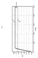
- Fig. 6 is a graph showing a temperature sensing signal of an IGBT temperature corrected from the temperature sensing signal corrector 100 according to one embodiment of the present invention.
- a temperature sensing signal c of an IGBT temperature corrected from the temperature sensing signal corrector 100 has no error from a section of about 0.01 sec.
- the temperature sensing signal corrector 100 can measure the IGBT temperature with precision by correcting a voltage drop of the temperature sensing signal occurring in the output limiting diode.
Landscapes
- Physics & Mathematics (AREA)
- General Physics & Mathematics (AREA)
- Nonlinear Science (AREA)
- Engineering & Computer Science (AREA)
- Theoretical Computer Science (AREA)
- Mathematical Physics (AREA)
- Data Mining & Analysis (AREA)
- Mathematical Optimization (AREA)
- Mathematical Analysis (AREA)
- Computational Mathematics (AREA)
- Pure & Applied Mathematics (AREA)
- Databases & Information Systems (AREA)
- Software Systems (AREA)
- General Engineering & Computer Science (AREA)
- Algebra (AREA)
- Power Conversion In General (AREA)
- Measuring Temperature Or Quantity Of Heat (AREA)
Applications Claiming Priority (1)
| Application Number | Priority Date | Filing Date | Title |
|---|---|---|---|
| KR1020160051149A KR20170122058A (ko) | 2016-04-26 | 2016-04-26 | 온도 측정 신호 보정 장치 |
Publications (1)
| Publication Number | Publication Date |
|---|---|
| EP3239675A1 true EP3239675A1 (fr) | 2017-11-01 |
Family
ID=57121151
Family Applications (1)
| Application Number | Title | Priority Date | Filing Date |
|---|---|---|---|
| EP16193107.6A Ceased EP3239675A1 (fr) | 2016-04-26 | 2016-10-10 | Appareil pour corriger le signal de mesure de température |
Country Status (5)
| Country | Link |
|---|---|
| US (1) | US10247625B2 (fr) |
| EP (1) | EP3239675A1 (fr) |
| JP (1) | JP6490653B2 (fr) |
| KR (1) | KR20170122058A (fr) |
| CN (1) | CN107314830B (fr) |
Cited By (2)
| Publication number | Priority date | Publication date | Assignee | Title |
|---|---|---|---|---|
| FR3083307A1 (fr) * | 2018-06-29 | 2020-01-03 | Sc2N | Capteur de temperature |
| EP3817230A1 (fr) * | 2019-10-28 | 2021-05-05 | Sansha Electric Manufacturing Co., Ltd. | Circuit de commande de grille |
Families Citing this family (10)
| Publication number | Priority date | Publication date | Assignee | Title |
|---|---|---|---|---|
| CN108572037B (zh) * | 2017-12-27 | 2019-06-28 | 中国科学院长春光学精密机械与物理研究所 | 一种规避自热效应的热敏电阻器稳态标定方法 |
| CN109659635B (zh) * | 2019-01-21 | 2023-11-03 | 安徽安凯汽车股份有限公司 | 一种温度显示装置 |
| CN111123061B (zh) * | 2019-12-26 | 2021-10-19 | 荣信汇科电气股份有限公司 | 一种快速响应的正反向管压降检测电路 |
| KR102842184B1 (ko) | 2020-03-13 | 2025-08-04 | 한국전자기술연구원 | 전력반도체 소자의 온도 측정을 위한 시험장치 및 그 온도측정 시험방법 |
| CN111933070A (zh) * | 2020-07-27 | 2020-11-13 | 重庆惠科金渝光电科技有限公司 | 驱动电路以及显示装置 |
| RU2764674C1 (ru) * | 2020-11-25 | 2022-01-19 | федеральное государственное бюджетное образовательное учреждение высшего образования "Ульяновский государственный технический университет" | Способ измерения теплового сопротивления переход-корпус и тепловых постоянных времени переход-корпус кристаллов полупроводниковых изделий в составе электронного модуля |
| US20220236117A1 (en) * | 2021-01-28 | 2022-07-28 | Marvell Asia Pte Ltd | Thermal Diode Sensor Self-Correction |
| US12339176B2 (en) * | 2022-07-28 | 2025-06-24 | Pixart Imaging Inc. | Electronic device and method for more accurately estimating resistance value of thermistor |
| KR102919133B1 (ko) * | 2022-08-30 | 2026-01-29 | 주식회사 경동나비엔 | 유도 가열 장치 및 유도 가열 장치의 제어 방법 |
| CN116659437B (zh) * | 2023-08-01 | 2023-09-22 | 深圳市艾姆克斯科技有限公司 | 一种基于大数据的比对仪零件监测系统 |
Citations (4)
| Publication number | Priority date | Publication date | Assignee | Title |
|---|---|---|---|---|
| GB939486A (en) * | 1960-06-02 | 1963-10-16 | Amos Nathan | Input converter for analogue multipliers |
| JP2004108875A (ja) * | 2002-09-17 | 2004-04-08 | Makita Corp | 温度検出回路 |
| JP2014070951A (ja) * | 2012-09-28 | 2014-04-21 | Sharp Corp | 温度検知回路 |
| KR101481290B1 (ko) * | 2013-07-09 | 2015-01-09 | 엘에스산전 주식회사 | 온도 검출 장치 및 이를 포함하는 인버터-충전기 통합 장치 |
Family Cites Families (16)
| Publication number | Priority date | Publication date | Assignee | Title |
|---|---|---|---|---|
| CA676182A (en) * | 1959-06-11 | 1963-12-17 | Antoszewski Eugeniusz | Temperature compensation of transistor amplifiers |
| GB2243994B (en) * | 1990-05-16 | 1994-02-16 | Samsung Electronics Co Ltd | Electric vacuum cleaner with an ozonizer |
| IL148862A0 (en) * | 1999-10-01 | 2002-09-12 | Online Power Supply Inc | Non-saturating magnetic element(s) power converters and surge protection |
| JP2004117111A (ja) | 2002-09-25 | 2004-04-15 | Toshiba Corp | 半導体装置 |
| CN100442190C (zh) * | 2003-01-13 | 2008-12-10 | 艾默生网络能源有限公司 | 电源输出端二极管压降的补偿电路及补偿方法 |
| US7356441B2 (en) * | 2005-09-28 | 2008-04-08 | Rockwell Automation Technologies, Inc. | Junction temperature prediction method and apparatus for use in a power conversion module |
| JP2007336728A (ja) | 2006-06-16 | 2007-12-27 | Hitachi Ltd | インバータ装置及びそれを用いたモータ駆動装置 |
| JP5188173B2 (ja) * | 2007-12-27 | 2013-04-24 | キヤノン株式会社 | 充電器 |
| US7826985B2 (en) * | 2008-05-02 | 2010-11-02 | Rockwell Automation Technologies, Inc. | Power module life estimation fatigue function |
| CN101771428A (zh) * | 2010-01-19 | 2010-07-07 | 青岛海信移动通信技术股份有限公司 | 一种温度检测电路及移动通信设备 |
| US8471516B2 (en) * | 2010-05-24 | 2013-06-25 | Rockwell Automation Technologies, Inc. | Adjustable speed drive lifetime improvement method |
| US9534962B2 (en) * | 2010-07-19 | 2017-01-03 | Mediatek Inc. | Temperature measurement devices |
| JP5590240B2 (ja) | 2011-07-06 | 2014-09-17 | 富士電機株式会社 | パワー半導体デバイスの電流補正回路および電流補正方法 |
| JP5861590B2 (ja) | 2012-07-30 | 2016-02-16 | 株式会社デンソー | 温度検出装置 |
| CN104867455B (zh) * | 2015-06-16 | 2017-05-03 | 深圳市华星光电技术有限公司 | 补偿amoled电压降的系统及方法 |
| CN205489504U (zh) * | 2016-02-04 | 2016-08-17 | 北京康斯特仪表科技股份有限公司 | 一种用于低压电压测量电路的抗高压保护电路 |
-
2016
- 2016-04-26 KR KR1020160051149A patent/KR20170122058A/ko not_active Abandoned
- 2016-10-10 EP EP16193107.6A patent/EP3239675A1/fr not_active Ceased
- 2016-11-01 CN CN201610935555.4A patent/CN107314830B/zh not_active Expired - Fee Related
- 2016-11-07 JP JP2016217634A patent/JP6490653B2/ja not_active Expired - Fee Related
- 2016-11-14 US US15/350,316 patent/US10247625B2/en active Active
Patent Citations (4)
| Publication number | Priority date | Publication date | Assignee | Title |
|---|---|---|---|---|
| GB939486A (en) * | 1960-06-02 | 1963-10-16 | Amos Nathan | Input converter for analogue multipliers |
| JP2004108875A (ja) * | 2002-09-17 | 2004-04-08 | Makita Corp | 温度検出回路 |
| JP2014070951A (ja) * | 2012-09-28 | 2014-04-21 | Sharp Corp | 温度検知回路 |
| KR101481290B1 (ko) * | 2013-07-09 | 2015-01-09 | 엘에스산전 주식회사 | 온도 검출 장치 및 이를 포함하는 인버터-충전기 통합 장치 |
Non-Patent Citations (1)
| Title |
|---|
| JOHN ANONYMOUS: "Diode Clipper Circuit - Positive,Negative,Biased,Combination clipper", WWW.CIRCUITSTODAY.COM, 4 April 2011 (2011-04-04), INTERNET, pages 1 - 5, XP055404945, Retrieved from the Internet <URL:http://www.circuitstoday.com/diode-clippers> [retrieved on 20170908] * |
Cited By (3)
| Publication number | Priority date | Publication date | Assignee | Title |
|---|---|---|---|---|
| FR3083307A1 (fr) * | 2018-06-29 | 2020-01-03 | Sc2N | Capteur de temperature |
| EP3817230A1 (fr) * | 2019-10-28 | 2021-05-05 | Sansha Electric Manufacturing Co., Ltd. | Circuit de commande de grille |
| US11901882B2 (en) | 2019-10-28 | 2024-02-13 | Sansha Electric Manufacturing Co., Ltd. | Gate drive circuit |
Also Published As
| Publication number | Publication date |
|---|---|
| US20170307450A1 (en) | 2017-10-26 |
| KR20170122058A (ko) | 2017-11-03 |
| JP6490653B2 (ja) | 2019-03-27 |
| US10247625B2 (en) | 2019-04-02 |
| CN107314830B (zh) | 2019-09-03 |
| JP2017198646A (ja) | 2017-11-02 |
| CN107314830A (zh) | 2017-11-03 |
Similar Documents
| Publication | Publication Date | Title |
|---|---|---|
| US10247625B2 (en) | Apparatus for correcting of temperature measurement signal | |
| ES2705433T3 (es) | Método para la compensación de deriva de temperatura de dispositivo de medición de temperatura que usa termopar | |
| US11293948B2 (en) | System and method for correcting current value of shunt resistor | |
| CN110994549B (zh) | 一种功率开关的过温保护方法及电路 | |
| US6783274B2 (en) | Device for measuring temperature of semiconductor integrated circuit | |
| CN110967549B (zh) | 电流采样方法和电流采样电路 | |
| US20170328786A1 (en) | Temperature detecting apparatus | |
| US11243223B2 (en) | Airflow velocity measuring apparatus and airflow rate measuring apparatus | |
| JP6151296B2 (ja) | 可変抵抗を用いる広範囲の電流計測 | |
| JP6151295B2 (ja) | デューティサイクリングを用いる広範囲の電流計測 | |
| JP5629016B2 (ja) | 自立的なセルバランシング | |
| US10031162B2 (en) | Current detection device and method for sensing an electric current | |
| JPWO2019130533A1 (ja) | 電力変換装置 | |
| US10823750B2 (en) | Wind speed measuring device and airflow measuring device | |
| CN112882505B (zh) | 温度保护信号生成电路及温度保护点修调方法 | |
| KR102332635B1 (ko) | 온도 감지 장치 및 방법 | |
| CN214751554U (zh) | 温度保护信号生成电路 | |
| US9903905B2 (en) | Semiconductor switch and method for determining a current through a semiconductor switch | |
| US11193835B2 (en) | Error compensation for sheathed sensors | |
| JP2005003596A (ja) | 抵抗測定装置、抵抗測定用集積回路及び抵抗測定方法 | |
| CN113686458B (zh) | 一种测温电路、测温设备及测温方法 | |
| KR101452615B1 (ko) | 온도 측정 방법 | |
| US10591332B2 (en) | Airflow meter | |
| JP2022141181A (ja) | ゲート駆動装置 | |
| JP2001147163A (ja) | 半導体素子の温度検出装置及び温度検出方法 |
Legal Events
| Date | Code | Title | Description |
|---|---|---|---|
| PUAI | Public reference made under article 153(3) epc to a published international application that has entered the european phase |
Free format text: ORIGINAL CODE: 0009012 |
|
| STAA | Information on the status of an ep patent application or granted ep patent |
Free format text: STATUS: THE APPLICATION HAS BEEN PUBLISHED |
|
| AK | Designated contracting states |
Kind code of ref document: A1 Designated state(s): AL AT BE BG CH CY CZ DE DK EE ES FI FR GB GR HR HU IE IS IT LI LT LU LV MC MK MT NL NO PL PT RO RS SE SI SK SM TR |
|
| AX | Request for extension of the european patent |
Extension state: BA ME |
|
| STAA | Information on the status of an ep patent application or granted ep patent |
Free format text: STATUS: REQUEST FOR EXAMINATION WAS MADE |
|
| 17P | Request for examination filed |
Effective date: 20180430 |
|
| RBV | Designated contracting states (corrected) |
Designated state(s): AL AT BE BG CH CY CZ DE DK EE ES FI FR GB GR HR HU IE IS IT LI LT LU LV MC MK MT NL NO PL PT RO RS SE SI SK SM TR |
|
| STAA | Information on the status of an ep patent application or granted ep patent |
Free format text: STATUS: EXAMINATION IS IN PROGRESS |
|
| 17Q | First examination report despatched |
Effective date: 20200108 |
|
| STAA | Information on the status of an ep patent application or granted ep patent |
Free format text: STATUS: THE APPLICATION HAS BEEN REFUSED |
|
| 18R | Application refused |
Effective date: 20220412 |