EP3239985B1 - Tige de combustible de réacteur à eau légère, et ensemble de combustible - Google Patents
Tige de combustible de réacteur à eau légère, et ensemble de combustible Download PDFInfo
- Publication number
- EP3239985B1 EP3239985B1 EP15902245.8A EP15902245A EP3239985B1 EP 3239985 B1 EP3239985 B1 EP 3239985B1 EP 15902245 A EP15902245 A EP 15902245A EP 3239985 B1 EP3239985 B1 EP 3239985B1
- Authority
- EP
- European Patent Office
- Prior art keywords
- cladding tube
- fuel
- plug
- fuel cladding
- fuel rod
- Prior art date
- Legal status (The legal status is an assumption and is not a legal conclusion. Google has not performed a legal analysis and makes no representation as to the accuracy of the status listed.)
- Active
Links
Images





Classifications
-
- G—PHYSICS
- G21—NUCLEAR PHYSICS; NUCLEAR ENGINEERING
- G21C—NUCLEAR REACTORS
- G21C3/00—Reactor fuel elements and their assemblies; Selection of substances for use as reactor fuel elements
- G21C3/02—Fuel elements
- G21C3/04—Constructional details
- G21C3/06—Casings; Jackets
- G21C3/10—End closures ; Means for tight mounting therefor
-
- G—PHYSICS
- G21—NUCLEAR PHYSICS; NUCLEAR ENGINEERING
- G21C—NUCLEAR REACTORS
- G21C21/00—Apparatus or processes specially adapted to the manufacture of reactors or parts thereof
- G21C21/02—Manufacture of fuel elements or breeder elements contained in non-active casings
-
- G—PHYSICS
- G21—NUCLEAR PHYSICS; NUCLEAR ENGINEERING
- G21C—NUCLEAR REACTORS
- G21C3/00—Reactor fuel elements and their assemblies; Selection of substances for use as reactor fuel elements
- G21C3/02—Fuel elements
- G21C3/04—Constructional details
- G21C3/06—Casings; Jackets
-
- G—PHYSICS
- G21—NUCLEAR PHYSICS; NUCLEAR ENGINEERING
- G21C—NUCLEAR REACTORS
- G21C3/00—Reactor fuel elements and their assemblies; Selection of substances for use as reactor fuel elements
- G21C3/02—Fuel elements
- G21C3/04—Constructional details
- G21C3/06—Casings; Jackets
- G21C3/07—Casings; Jackets characterised by their material, e.g. alloys
-
- G—PHYSICS
- G21—NUCLEAR PHYSICS; NUCLEAR ENGINEERING
- G21C—NUCLEAR REACTORS
- G21C3/00—Reactor fuel elements and their assemblies; Selection of substances for use as reactor fuel elements
- G21C3/30—Assemblies of a number of fuel elements in the form of a rigid unit
-
- Y—GENERAL TAGGING OF NEW TECHNOLOGICAL DEVELOPMENTS; GENERAL TAGGING OF CROSS-SECTIONAL TECHNOLOGIES SPANNING OVER SEVERAL SECTIONS OF THE IPC; TECHNICAL SUBJECTS COVERED BY FORMER USPC CROSS-REFERENCE ART COLLECTIONS [XRACs] AND DIGESTS
- Y02—TECHNOLOGIES OR APPLICATIONS FOR MITIGATION OR ADAPTATION AGAINST CLIMATE CHANGE
- Y02E—REDUCTION OF GREENHOUSE GAS [GHG] EMISSIONS, RELATED TO ENERGY GENERATION, TRANSMISSION OR DISTRIBUTION
- Y02E30/00—Energy generation of nuclear origin
- Y02E30/30—Nuclear fission reactors
Definitions
- the present invention relates to a fuel assembly loaded into the reactor core of a nuclear reactor, and particularly to nuclear fuel rods and fuel assemblies loaded into the reactor core of a light water reactor.
- Light water reactors such as boiling-water reactors (BWR) and pressurized-water reactor (PWR) typically include fuel assemblies loaded into the reactor core as nuclear fuel.
- the fuel assembly includes a plurality of uranium-containing nuclear fuel rods (or simply, “fuel rods”) arrayed and supported with an upper tie plate and a lower tie plate.
- Each nuclear fuel rod includes uranium fuel pellets charged into a fuel cladding tube about 4 meters long, and the both ends of the tube are sealed with end plugs .
- a zirconium alloy zircalloy
- This material has good neutron economy, and has been safely used in typical nuclear reactor environments.
- LOCA loss-of-coolant accident
- ECCS emergency core cooling system
- SiC silicon carbide
- LOCA loss-of-coolant accident
- PTL 1 proposes a fuel cladding tube and end plugs configured from a SiC material.
- PTL 1 discloses a configuration in which a fuel cladding tube, and end plugs for sealing the both end portions of the fuel cladding tube are formed of a SiC fiber reinforced composite reinforced with silicon carbide continuous fibers, and in which the fuel cladding tube and the end plugs are directly joined to each other without interposing a dissimilar material, in at least a joint portion that comes into contact with the reactor coolant.
- This publication also describes a configuration in which the fuel cladding tube and the end plugs are directly joined to each other without interposing a dissimilar material on the side that comes into contact with the reactor coolant (the outer periphery surface side of the fuel cladding tube), and in which the side that does not come into contact with the reactor coolant (the inner periphery surface side of the fuel cladding tube) is joined by solid-state welding via a dissimilar material (a composite of titanium silicon carbide and titanium silicide, or silicon carbide containing aluminum and yttrium) .
- a dissimilar material a composite of titanium silicon carbide and titanium silicide, or silicon carbide containing aluminum and yttrium
- PTL 2 describes a multi-layered ceramic tube having an inner layer of high purity beta phase stoichiometric silicon carbide, a central composite layer of continuous beta phase stoichiometric silicon carbide fibers, and an outer layer of fine-grained silicon carbide.
- PTL 3 a nuclear fuel element for use in water-cooled nuclear power reactors is presented.
- the fuel element includes a multilayered silicon carbide cladding tube which preferably includes an inner layer and a central layer.
- the end-plug joints of a fuel rod where the solid end plugs and the hollow fuel cladding tube are connected to each other are regions that undergo abrupt changes in cross sectional area. Accordingly, an applied bending load on the fuel rod with the fixed end plugs translates into a concentrated stress at the end-plug joints.
- the end-plug joints of a traditional zirconium alloy fuel rod undergo plastic deformation under an applied stress that exceeds the proof strength, and cracks do not penetrate through the fuel rod until the applied stress reaches a stress at rupture.
- the end-plug joints connecting the fuel cladding tube and the end plugs using a ceramic base material do not undergo plastic deformation, and a crack propagates once it generates. The crack has a high probability of penetrating through the fuel rod.
- the configuration of PTL 1 has the risk of a crack propagating toward the outer periphery surface of the fuel cladding tube or the end plugs along the joint surface, and penetrating into the fuel cladding tube or the end plugs.
- a fuel rod for light water reactors of the present invention includes:
- a fuel assembly according to the present invention is a fuel assembly that includes a plurality of fuel rods bundled with a spacer, and that is to be loaded into a reactor core of a nuclear reactor, wherein the fuel rods include:
- the present invention can provide a fuel rod and a fuel assembly for light water reactors in which crack penetration to a fuel cladding tube or end plugs can be prevented even when cracking occurs at the joint between the fuel cladding tube and the end plugs for which a ceramic base material is used.
- FIG. 1 is a partial schematic cross sectional view of a nuclear fuel rod according to an embodiment of the present invention.
- a nuclear fuel rod 10a according to the present embodiment includes a fuel cladding tube 11, and a lower end-plug 12a and an upper end-plug 12b joined to the ends of the fuel cladding tube 11 to seal the fuel cladding tube 11.
- the fuel cladding tube 11 is charged with a plurality of fuel pellets 13.
- the nuclear fuel rod 10a is provided with a retainer spring 15 to retain the fuel pellets 13 charged inside the cylindrical fuel cladding tube 11.
- the upper end portion of the retainer spring 15 is connected to the upper end-plug 12b, and the lower end portion of the retainer spring 15 presses the fuel pellets 13.
- the fuel cladding tube 11, the upper end-plug 12a, and the lower end-plug 12b are configured from a ceramic base material. The following descriptions will be given through the case where these components are configured from a silicon carbide (SiC) material.
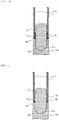
- FIG. 2 is an enlarged schematic cross sectional view representing an example of the joint between the fuel cladding tube and the end plug of a comparative example.
- the joint illustrated in FIG. 2 is the joint between the fuel cladding tube 11 and the lower end-plug 12a.
- the structure is the same for the joint between the upper end-plug 12b and the fuel cladding tube 11.
- the fuel pellets 13 charged inside the fuel cladding tube 11 are omitted to more clearly illustrate the joint between the fuel cladding tube 11 and the lower end-plug 12a.
- the lower end-plug 12a is a solid columnar member with a straight barrel insert 12c projecting into the fuel cladding tube 11 in a region other than the outer edge portion.
- the outer diameter of the straight barrel insert 12c is slightly smaller than the inner diameter of the fuel cladding tube 11, and the lower end-plug 12a has an outer diameter about the same as the outer diameter of the fuel cladding tube 11.
- the circular step with a flat top surface faces the lower end surface of the fuel cladding tube 11, and represents a butt joint interface 12d that is joined to the lower end surface of the fuel cladding tube 11 via a metallic joint material 20.
- a repeated stress during normal operation often acts to push the hollow cylindrical fuel cladding tube 11 outward.
- a repeated stress pushes the hollow cylindrical fuel cladding tube 11 in a direction that increases the inner diameter and the outer diameter of the fuel cladding tube 11.
- the displacement of the fuel cladding tube 11 becomes greater toward the upper side of FIG. 2 , from the butt joint interface 12d of the lower end-plug 12a, specifically from the base of the straight barrel insert 12c.
- cracking due to a repeated stress is believed to occur most frequently in the vicinity of the uppermost part of the metallic joint material 20 that is in contact with the outer periphery surface of the straight barrel insert 12c in the gap between the inner periphery surface of the fuel cladding tube 11 and the straight barrel insert 12c.
- a crack generated at the uppermost part of the interface between the metallic joint material 20 and the straight barrel insert 12c propagates downwardly toward the base of the straight barrel insert 12c along the outer periphery surface of the straight barrel insert 12c.
- the crack Upon reaching the base of the straight barrel insert 12c, the crack radially propagates at the interface between the butt joint interface 12d of the lower end-plug 12a and the metallic joint material 20 toward the outer periphery portion of the circular butt joint interface 12d, before possibly penetrating through the nuclear fuel rod.
- FIG. 3 is an enlarged schematic cross sectional view representing another example of the joint between the fuel cladding tube and the end plugs of the comparative example.
- the difference from the comparative example represented in FIG. 2 is that the butt joint interface 12d of the lower end-plug 12a in FIG. 3 is slanted with respect to the axial direction of the fuel cladding tube 11.
- the butt joint interface 12d of the lower end-plug 12a has a slanted surface so that the diameter of the lower end-plug 12a constituting the butt joint interface 12d increases toward the lower side of FIG. 3 from the base of the straight barrel insert 12c.
- the fuel cladding tube 11 has lower end surface of a shape that conforms to the butt joint interface 12d of the lower end-plug 12a. Specifically, the lower end surface of the fuel cladding tube 11 is slanted so that the inner diameter of the fuel cladding tube 11 increases toward the lower end-plug 12a. In the structure of the comparative example represented in FIG. 3 , a repeated stress pushes the hollow cylindrical fuel cladding tube 11 outward, as with the case of FIG. 2 .
- a crack generated at the interface between the straight barrel insert 12c and the metallic joint material 20 is more likely to propagate along the outer periphery surface of the straight barrel insert 12c, and the interface between the butt joint interface 12d of the lower end-plug 12a and the metallic joint material 20, and penetrate through the nuclear fuel rod than in the configuration of FIG. 2 .
- FIG. 4 is an enlarged schematic cross sectional view representing an example of the joint between the fuel cladding tube 11 and the lower end-plug 12a constituting the nuclear fuel rod 10a according to the embodiment of the present invention shown in FIG. 1 .
- the joint illustrated in FIG. 4 is the joint between the fuel cladding tube 11 and the lower end-plug 12a.
- the structure is the same for the joint between the upper end-plug 12b and the fuel cladding tube 11 shown in FIG. 1 .
- the fuel pellets 13 charged inside the hollow cylindrical fuel cladding tube 11 are omitted to more clearly illustrate the joint between the fuel cladding tube 11 and the lower end-plug 12a.
- the lower end-plug 12a is a solid columnar member with a concave portion 12f of a curved surface shape provided at an upper region including the butt joint interface 12d to be joined to the lower end surface of the fuel cladding tube 11.
- the concave portion 12f of a curved surface shape is a portion with a depression approximated to a portion of a spherical surface in the vicinity of the bottom portion, and a cylindrical portion having an inner surface that is continuous to the depression.
- the upper end surface of the lower end-plug 12a defining the concave portion 12f of a curved surface shape represents the butt joint interface 12d that can be brought into contact with the butt joint interface 11a (described later) representing the lower end surface of the fuel cladding tube 11.
- the butt joint interface 12d of the lower end-plug 12a has a surface that is slanted upward from the inner periphery surface side to the outer periphery surface side (toward the fuel cladding tube 11).
- the butt joint interface 12d of the lower end-plug 12a has such a shape that the inner diameter of the concave portion 12f of a curved surface shape becomes larger toward the fuel cladding tube 11.
- the butt joint interface 12d which appears circular as viewed from the top, has a shape similar to the shape of an inverted hollow circular cone that becomes taller from the inner diameter to the outer diameter side.
- the butt joint interface 11a representing the lower end surface of the fuel cladding tube 11 facing the butt joint interface 12d of the lower end-plug 12a is a surface that is slanted upward from the inner periphery surface side to the outer periphery surface side of the fuel cladding tube 11.
- the butt joint interface 11a of the fuel cladding tube 11 has a surface that is slanted toward the lower end-plug 12a from the outer periphery surface side to the inner periphery surface side of the fuel cladding tube 11. As illustrated in FIG.
- the nuclear fuel rod 10a also has a connection 21 that is disposed in a region extending from the concave portion 12f of a curved surface shape of the lower end-plug 12a to a predetermined height inside the fuel cladding tube 11 past the butt joint interface 12d of the lower end-plug 12a and the butt joint interface 11a of the fuel cladding tube 11.
- the connection 21 has a solid columnar portion, and a curved surface portion 21a approximated to a portion of a spherical surface, and provided at one end or both ends of the connection 21 relative to the lengthwise direction.
- the columnar portion and the curved surface portion 21a have outer surfaces that are continuous to each other. In the example represented in FIG.
- connection 21 having the curved surface portion 21a approximated to a portion of a spherical surface is shown opposite the depression of the concave portion 12f of a curved surface shape of the lower end-plug 12a.
- the connection 21 supports the fuel cladding tube 11 and the lower end-plug 12a.
- the curved surface portion 21a of the connection 21 approximated to a portion of a spherical surface, and the depression of the concave portion 12f of a curved surface shape of the lower end-plug 12a should have as large a curvature as possible, or should be approximated to a sphere having as large a radius as possible.
- the inner periphery surface of the fuel cladding tube 11, and the outer periphery surface of the connection 21 are joined to each other with the metallic joint material 20 in a region including the butt joint interface 12d of the lower end-plug 12a and the butt joint interface 11a of the fuel cladding tube 11, and covering a predetermined distance above the end portion of the butt joint interface 12d opposite the connection 21.
- the metallic joint material 20 may flow into the gap formed between the outer periphery surface of the connection 21 and the inner periphery surface of the concave portion 12f of a curved surface shape of the lower end-plug 12a, or may be applied beforehand to the outer periphery surface of the connection 21, or to the concave portion 12f of a curved surface shape of the lower end-plug 12a, and the gap may be closed with the metallic joint material 20 at the time of joining.
- the base of the straight barrel insert 12c constituting the lower end-plug 12a (a region in the vicinity of the joint between the fuel cladding tube 11 and the lower end-plug 12a) is a region where the transverse sectional area of the solid lower end-plug 12a undergoes abrupt changes.
- abrupt changes in the transverse sectional area of the solid lower end-plug 12a take place at the depression approximated to a portion of a spherical surface in the concave portion 12f of a curved surface shape of the lower end-plug 12a.
- a stress due to applied bending load concentrates in the vicinity of the depression of the concave portion 12f of a curved surface shape, distant away from the butt joint interface 11a of the cladding tube 11 and the butt joint interface 12d of the lower end-plug 12a where the fuel cladding tube 11 and the lower end-plug 12a are joined to each other. Further, the stress concentration itself is relaxed because the depression of the concave portion 12f of a curved surface shape of the lower end-plug 12a has a shape approximated to a portion of a spherical surface.
- a crack that has propagated through the interface between the metallic joint material 20 and the outer periphery surface of the connection 21 propagates along the inner surface of the concave portion 12f of a curved surface shape of the lower end-plug 12a below, and the outer surface of the connection 21, and stays inside the nuclear fuel rod 10a.
- any crack propagation into the connection 21 does not pose a problem because the crack does not penetrate the nuclear fuel rod 10a.
- a silicon carbide (SiC) material is used for the fuel cladding tube 11, the lower end-plug 12a, and the connection 21. It is particularly preferable that the fuel cladding tube 11 and the lower end-plug 12a use a silicon carbide fiber reinforced silicon carbide composite material containing silicon carbide fibers in a silicon carbide matrix (hereinafter, also referred to as "SiC/SiC composite material").
- the SiC/SiC composite material used has a SiC layer formed on a part of the surface (for example, in a region corresponding to the joint surface) .
- the method used to form the SiC layer is not particularly limited, and methods, for example, such as a chemical vapor deposition method (CVD method), and a coating and sintering method may be used.
- the fuel cladding tube 11 and the lower end-plug 12a In order to shield the SiC itself from the coolant water environment inside the nuclear reactor, it is preferable to coat the fuel cladding tube 11 and the lower end-plug 12a with a Zr-, Ti-, or Cr-based alloy or compound of a thickness of about at most 100 ⁇ m.
- the method used to form such an environmental barrier coating is not particularly limited, and methods, for example, such as a physical vapor deposition method (PVD method), a chemical vapor deposition method (CVD method), and a coating and sintering method may be used.
- the fuel cladding tube 11 has the same dimensions as traditional fuel cladding tubes of a zirconium alloy.
- the fuel cladding tube 11 has a length of about 4 m, an outer diameter of about 11mm, and a thickness of about 1 mm.
- the lower end-plug 12a has such a shape or dimensions that no step is created on the outer surface in the vicinity of the joint made upon joining the butt joint interface 12d to the butt joint interface 11a of the fuel cladding tube 11.
- the outer diameter of the connection 21 is preferably smaller than the inner diameter of the fuel cladding tube 11 by a moderate amount of clearance (for example, about 0.02 to 0.5 mm).
- the metallic joint material 20 may be preferably one selected from Si (melting point: 1,414°C), Ti (melting point: 1,812°C), Zr (melting point: 1,855°C), and a Si alloy, a Ti alloy, and a Zr alloy of a composition with a solidus temperature of 1,200°C or more.
- the nuclear fuel rod 10a can remain air-tight even in a rare case where the nuclear fuel rod 10a reaches a temperature as high as 1,200°C.
- the following describes a method for joining the fuel cladding tube 11 and the lower end-plug 12a to each other.
- a coating of the metallic joint material 20 is formed on at least one of the butt joint interface 11a of the fuel cladding tube 11 and the butt joint interface 12d of the lower end-plug 12a that are to be joined to each other, and on at least one of the inner periphery surface of the fuel cladding tube 11 and the outer periphery surface of the connection 21.
- the coating thickness is thick enough to close the clearance (the gap between the inner diameter of the fuel cladding tube 11 and the outer diameter of the connection 21) (for example, a thickness of about 0.01 to 0.25 mm).
- the lower end-plug 12a can be prevented from becoming loose or falling off when the butt joint interface 11a of the fuel cladding tube 11 is brought into contact with the butt joint interface 12d of the lower end-plug 12a, and when the connection 21 is inserted in the fuel cladding tube 11, and in the concave portion 12f of a curved surface shape of the lower end-plug 12a.
- the method used for the coating of the metallic joint material 20 is not particularly limited, and known methods, for example, such as vapor deposition, spraying, cold spraying, and melting may be used.
- the fuel cladding tube 11 and the lower end-plug 12a are then heated while being pressed against each other to join the fuel cladding tube 11, the lower end-plug 12a, and the connection 21.
- the fuel pellets 13 have not been charged into the fuel cladding tube 11, and the fuel cladding tube 11 on the side of the upper end-plug 12b has an open end.
- the fuel pellets 13 are then charged into the fuel cladding tube 11, and, after the insertion of the retainer spring 15, the butt joint interface of the upper end-plug 12b is brought into contact with the butt joint interface of the fuel cladding tube 11. These are then joined to each other under heat.
- heat may be applied to the whole fuel cladding tube 11, including the joint with the lower end-plug 12a.
- heat is applied locally to the joint so that the fuel pellets 13 are not heated.
- the heating method is not particularly limited, and known methods, for example, such as wide heating with a long heating furnace, and local heating with a laser, or a high-frequency or local heater may be used.
- the metallic joint material 20 used in the present embodiment has an average linear coefficient of expansion of preferably less than 10 ppm/K.
- the thermal stress due to temperature fluctuations (thermal expansion and thermal shrinkage) of the nuclear fuel rod 10a can be minimized, and joint damage can be prevented when the material used as the metallic joint material 20 has an average linear coefficient of expansion that does not differ greatly from the average linear coefficient of expansion (4.3 to 6.6 ppm/K) of the SiC material to be joined by the metallic joint material 20.
- the effect may not be obtained when the metallic joint material 20 has an average linear coefficient of expansion of 10 ppm/K or more, and the long-term reliability of the nuclear fuel rod 10a as a whole may be lost in this case.
- FIG. 5 is an enlarged schematic cross sectional view representing another example of the joint between the fuel cladding tube 11 and the lower end-plug 12a shown in FIG. 1 .
- a threaded structure 12e is provided on the inner periphery surface of the hollow cylindrical fuel cladding tube 11, the inner periphery surface of the cylindrical portion constituting the concave portion 12f of a curved surface shape of the lower end-plug 12a, and the outer periphery surface of the solid columnar portion of the connection 21.
- the reliability of the joint strength can be further improved by mechanically fastening the fuel cladding tube 11 and the lower end-plug 12a with the threaded structure 12e via the connection 21.
- the threaded structure 12e is preferably a wide threaded structure (for example, shallow thread depth, and a wide thread pitch) .
- a wide threaded structure may be used as long as the connection 21 can remain screwed and attached to the fuel cladding tube 11 and the lower end-plug 12a under the frictional force between the screwed external thread and internal thread.
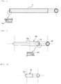
- FIG. 6 shows a side view and an elevational view of the fuel cladding tube 11 shown in FIG. 1 , along with an enlarged cross sectional view of the joint shape of the fuel cladding tube 11.
- FIG. 7 shows a side view and an elevational view of the lower end-plug 12a shown in FIG. 1 , along with an enlarged cross sectional view of the joint shape of the lower end-plug 12a.
- FIG. 8 shows a side view and an elevational view of the connection 21 disposed in a joint region inside the fuel cladding tube 11 and the lower end-plug 12a shown in FIGS. 6 and 7 .
- the butt joint interface 11a formed at the end portion of the hollow cylindrical fuel cladding tube 11 has a slanted surface that makes the outer diameter of the fuel cladding tube 11 smaller toward the tip, as shown in the enlarged cross sectional view.
- the butt joint interface 11a creates a slope angle ⁇ a with the inner periphery surface of the fuel cladding tube 11.
- the butt joint interface 11a is slanted with a slope angle ⁇ a with respect to the axial direction of the fuel cladding tube 11.
- the butt joint interface 12d formed at the end portion of the cylindrical portion constituting the concave portion 12f of a curved surface shape of the lower end-plug 12a (the end portion on the right-hand side of the side view in FIG. 7 ) has a slanted surface that makes the inner diameter of the cylindrical portion constituting the concave portion 12f of a curved surface shape larger toward the tip, as shown in the enlarged cross sectional view.
- the butt joint interface 12d creates a slope angle ⁇ b with the inner periphery surface of the cylindrical portion constituting the concave portion 12f of a curved surface shape.
- the butt joint interface 12d is slanted with a slope angle ⁇ b with respect to the axial direction of the lower end-plug 12a.
- the slope angles ⁇ a and ⁇ b are the same, and allow contact between the butt joint interface 11a of the fuel cladding tube 11 and the butt joint interface 12d of the lower end-plug 12a.
- the alignment accuracy between the fuel cladding tube 11 and the lower end-plug 12a can improve with the slope angle ⁇ a provided at the butt joint interface 11a of the fuel cladding tube 11, and the slope angle ⁇ b provided at the butt joint interface 12d of the lower end-plug 12a. This also increases the joint area between the butt joint interface 11a and the butt joint interface 12d, and can improve the joint strength and air-tightness.
- the slope angles ⁇ a and ⁇ b are preferably 30 to 80°, desirably 45 to 60°.
- the alignment accuracy improving effect can be obtained with slope angles ⁇ a and ⁇ b larger than 80°.
- these angles are not sufficient to reduce crack propagation to the butt joint interface 12d. Processibility suffers, and chipping tends to occur at the tips of the butt joint interfaces 11a and 12d when the slope angles ⁇ a and ⁇ b are less than 30°.
- the lower end-plug 12a has an outer diameter constriction 12g in a region that interdigitates with the lower tie plate of a fuel assembly (not illustrated), at a predetermined distance to the left along the lengthwise direction from the right dashed-dotted line of the side view.
- the outer diameter constriction 12g has such a shape that makes the outer diameter gradually smaller toward the tip of the lower end-plug 12a (toward the end portion on the left-hand side of the side view in FIG. 7 ). Specifically, the outer diameter constriction 12g is gradually sloped.
- the connection 21 is configured from a columnar portion, and a curved surface portion 21a approximated to a portion of a spherical surface, as shown in the side view of FIG. 8 .
- FIG. 9 is a partial schematic cross sectional view of a nuclear fuel rod according to another embodiment of the present invention.
- the nuclear fuel rod 10b according to the present embodiment differs from the nuclear fuel rod 10a shown in FIG. 1 in that a joint covering 14 of a coating metal having high corrosion resistance is provided over the outer periphery surface including the joint between the lower end-plug 12a and the fuel cladding tube 11, and the outer periphery surface including the joint between the upper end-plug 12b and the fuel cladding tube 11.
- FIG. 10 is an enlarged schematic cross sectional view representing an example of the joint between the fuel cladding tube 11 and the lower end-plug 12a shown in FIG. 9 .
- FIG. 11 is an enlarged schematic cross sectional view representing an example of the joint between the fuel cladding tube 11 and the lower end-plug 12a shown in FIG. 9 .
- the joint covering 14 covers the butt joint interface 11a of the fuel cladding tube 11, and the butt joint interface 12d of the lower end-plug 12a.
- the lower end of the joint covering 14 is below the depression constituting the concave portion 12f of a curved surface shape of the lower end-plug 12a.
- the upper end of the joint covering 14 is above the upper end portion of the connection 21 disposed in the fuel cladding tube 11 and in the concave portion 12f of a curved surface shape of the lower end-plug 12a.
- the 11 also covers the butt joint interface 11a of the fuel cladding tube 11 and the butt joint interface 12d of the lower end-plug 12a, and has a lower end below the depression constituting the concave portion 12f of a curved surface shape of the lower end-plug 12a, and an upper end above the upper end portion of the connection 21 disposed in the fuel cladding tube 11 and in the concave portion 12f of a curved surface shape of the lower end-plug 12a.
- the nuclear fuel rod 10b of the present embodiment has the joint covering 14 having high corrosion resistance covering the outer periphery surface including the joint between the lower end-plug 12a and the fuel cladding tube 11, and the outer periphery surface including the joint between the upper end-plug 12b and the fuel cladding tube 11. This further improves the joint strength compared to the nuclear fuel rods 10a shown in FIGS. 1 , 4, and 5 .
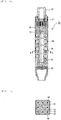
- FIG. 12 is a schematic longitudinal sectional view of a fuel assembly according to an embodiment of the present invention.
- FIG. 13 is a cross sectional view of the fuel assembly of FIG. 12 at A - A.
- the fuel assembly 30 shown in FIGS. 12 and 13 is an example of a fuel assembly for boiling-water reactors (BWR), and includes an upper tie plate 31, a lower tie plate 32, a plurality of nuclear fuel rods 10 held to the upper tie plate 31 and the lower tie plate 32 at the both ends, water rods 33 (also referred to as water channels), a fuel support grid (spacer) 34 binding the nuclear fuel rods, and a channel box 35 attached to the upper tie plate 31 and surrounding the fuel rods bundled by the fuel support grid 34.
- a handle 37 is fastened to the upper tie plate 31, so that the whole fuel assembly 30 can be pulled up by lifting the handle 37.
- Some of the nuclear fuel rods are short part-length rods 36 of a height that does not reach the upper tie plate 31.
- the short part-length rods 36 are nuclear fuel rods of a height that does not reach the upper tie plate 31, with a shorter effective fuel length than the nuclear fuel rods 10 (also called long part-length rods) inside the assembly.
- the nuclear fuel rods 10 (long part-length rods), the short part-length rods 36, and the water rods 33 are bundled in a square grid pattern, and housed inside the channel box 35 having a square-shaped transverse section.
- two water rods 33 are disposed at substantially the center of a transverse section of the channel box 35, and each water rod 33 is disposed in a grid region that can accommodate four nuclear fuel rods 10 (long part-length rods) .
- the water rods 33 in the fuel assembly 30 may be zirconium alloy water rods. However, considering a rare but possible incidence of loss-of-coolant accident (LOCA), it is preferable that the water rods 33 have the same configuration as the nuclear fuel rods 10, specifically a configuration with a hollow tube and end plugs made of a SiC material, and in which the hollow tube and the end plugs are joined to each other via the metallic joint material 20.
- the water rods 33 also may have a configuration in which the joint covering 14 covers the joint area where the hollow tube and the end plugs are joined to each other via the metallic joint material 20.
- the method used to form the environmental barrier coating is not particularly limited, and methods, for example, such as a physical vapor deposition method (PVD method), a chemical vapor deposition method (CVD method), and a coating and sintering method may be used.
- PVD method physical vapor deposition method
- CVD method chemical vapor deposition method
- coating and sintering method may be used.
- FIG. 14 is a schematic transverse sectional view representing an example of a boiling-water reactor cell.
- a cell 40 of a boiling-water reactor has four fuel assemblies 30 that are disposed in a square pattern, and control rods 41 that are arranged in a substantially crossed pattern at the center in a transverse section.
- the cell 40 can have improved safety against emergency situations (for example, a loss-of-coolant accident) while maintaining the current level of long-term reliability under a normal operating environment.
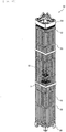
- FIG. 15 is a partially transparent external perspective view of a fuel assembly loaded into a pressurized-water reactor.
- the fuel assembly 50 is an example of a fuel assembly for pressurized-water reactors (PWR), and includes a plurality of nuclear fuel rods 10, a plurality of control rod guide thimbles 51, an incore instrumentation guide thimble 52, a plurality of support grids (spacers) 53 that bundles and supports these components, an upper nozzle 54, and a lower nozzle 55.
- the upper nozzle 54 and the lower nozzle 55 are provided as frame members of the fuel assembly 50, and to locate the fuel assembly 50 in the reactor core, or to provide channels for coolant water.
- the incore instrumentation guide thimble 52 is provided to guide incore instrumentation devices, such as a local power range monitor (LPRM), and an average power range monitor (APRM), to the reactor core.
- LPRM local power range monitor
- APRM average power range monitor
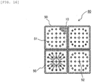
- FIG. 16 is a schematic transverse sectional view representing an example of a pressurized-water reactor cell.
- four fuel assemblies 50 are directly disposed in a square pattern in the pressurized-water reactor (PWR) cell 60 because the fuel assemblies 50 have control rods therein.
- the cell 60 also can have improved safety against emergency situations (for example, a loss-of-coolant accident) while maintaining the current level of long-term reliability under a normal operating environment.
- the present invention is not limited to these embodiments.
- the present invention is also applicable to a hollow tubular body (cladding tube) configured from common oxide ceramic materials, namely alumina (Al2O3), zirconia (Zr02), and mullite (Al6013Si2) and having lids made of such materials, and that is sealed against high temperature and/or high pressure, and exposed to a corrosive environment.
- a plurality of metallic joint materials 20 was prepared, and experiments were conducted by joining a SiC mock fuel cladding tube and a SiC mock end plug.
- the SiC mock fuel cladding tube and the SiC mock end plug were used after forming a SiC layer on the surfaces.
- Table 1 shows details of the metallic joint materials prepared. [Table 1] Details of metal joint materials Heating temperature in electric furnace Material Composition (mass%) Solidus temperature (°C) Average linear coefficient of expansion (ppm/K) Joint material SiC 2,730 4.3 to 6.6 Ex. 1 1,450 to 1,514°C Si C: 0.08% or less, Si: bal. 1,404 to 1,414 3.3 Ex. 2 1,250 to 1,514°C Si alloy Ge: 50% or less, C: 0.08% or less, Si: bal.
- the metallic joint material used in Example 1 contained 0.08% or less C, and the balance Si.
- the metallic joint material used in Example 2 contained 50% or less Ge, 0.08% or less C, and the balance Si.
- the metallic joint material used in Example 3 contained 5% or less Mo, 20% or less W, 40% or less Fe, and the balance Si.
- the metallic joint material used in Example 4 contained 2% or less Ti, 2% or less Zr, 2% or less Ta, 2% or less Nb, 2% or less V, 2% or less Y, 2% or less Cr, and the balance Si.
- the metallic joint material used in Example 5 contained 0.3% or less Fe, 0.08% or less C, and the balance Ti.
- the metallic joint material used in Example 6 contained 50% Zr, 0.3% or less Fe, 0.08% or less C, and the balance Ti.
- the metallic joint material used in Example 7 contained 0.3% or less Fe, 0.08% or less C, and the balance Zr.
- the metallic material used in Example 8 contained 1.2 to 1.7% Sn, 0.03 to 0.08% Ni, 0.07 to 0.2% Fe, 0.05 to 0.15% Cr, 0.005% or less Ti, and the balance Zr.
- the metallic joint material used in Example 9 contained 1.2 to 1.7% Sn, 0.18 to 0.24% Fe, 0.07 to 0.13% Cr, 0.005% or less Ti, and the balance Zr.
- the metallic joint material used in Example 10 contained 1 to 2.5% Nb, 0.005% or less Ti, and the balance Zr.
- a SiC mock fuel cladding tube, and a SiC mock end plug were prepared that had a SiC layer formed on the surface, and the metallic joint material (thickness of about 0.2 mm) of each Example was deposited on the SiC mock fuel cladding tube and the SiC mock end plug on one of the surfaces, using a vapor deposition method.
- the SiC mock fuel cladding tube, and the SiC mock end plug were then butted (contacted) to each other with the deposited metallic joint material coatings facing each other, and subjected to a compression heat treatment (under a stream of argon) with an electric furnace.
- the heating temperature was 1,450 to 1,514°C in Examples 1 and 4, 1,250 to 1, 514°C in Examples 2 and 3, and 1,200 to 1, 400°C in Examples 5 to 10.
- a joint cross section was polished, and the microstructure of the joint region was observed under a light microscope.
- Examples 1 to 4 Si, and a Si alloy
- Examples 5 to 10 Ti, a Ti alloy, Zr, and a Zr alloy
- Examples 5 to 10 had microstructures primarily from diffusion joining (diffusion joint structure). Cracks or communicating gas pockets were not observed in the joint region in any of the Examples.
Landscapes
- Engineering & Computer Science (AREA)
- Physics & Mathematics (AREA)
- Plasma & Fusion (AREA)
- General Engineering & Computer Science (AREA)
- High Energy & Nuclear Physics (AREA)
- Manufacturing & Machinery (AREA)
- Metallurgy (AREA)
- Monitoring And Testing Of Nuclear Reactors (AREA)
- Pressure Welding/Diffusion-Bonding (AREA)
Claims (10)
- Barre de combustible (10, 10a, 10b) pour des réacteurs à eau légère, comprenant :un tube de revêtement cylindrique (11) formé d'un matériau de base céramique,caractérisée en ce quele matériau de base céramique est représenté par du carbure de silicium (SiC), de l'alumine (AlO3), du zircone (ZrO2) et/ou de la mullite (Al6O13Si2), une connexion (21) formée du même matériau que le tube de revêtement (11); etun bouchon d'extrémité (12a, 12b) ayant une portion concave d'une forme de surface incurvée en continu (12f) adaptée pour abriter la connexion (21), dans laquelle le bouchon d'extrémité (12a, 12b) est formé du même matériau que le tube de revêtement (11),dans laquelle une surface oblique, formée au niveau d'une portion d'extrémité du tube de revêtement (11), et une surface oblique formée à une portion d'extrémité du bouchon d'extrémité (12a, 12b) sont jointes en contact l'une avec l'autre avec un matériau de jonction métallique (20) et supportées par la connexion (21).
- Barre de combustible (10, 10a, 10b) pour des réacteurs à eau légère selon la revendication 1,
dans laquelle la connexion (21) inclut une portion en forme de colonne et une portion de surface incurvée (21a) qui est prévue à une extrémité ou aux deux extrémités de la direction en longueur de la portion en forme de colonne, et qui représente approximativement une portion d'une surface sphérique, et dans laquelle la portion en forme de colonne et la portion de surface incurvée (21a) ont des surfaces extérieures qui sont en continu l'une avec l'autre. - Barre de combustible (10, 10a, 10b) pour des réacteurs à eau légère selon la revendication 2,
dans laquelle la portion concave (12f) d'une forme de surface incurvée du bouchon d'extrémité (12a, 12b) a une portion cylindrique opposée à la portion en forme de colonne de la connexion (21) avec un intervalle prédéterminé entre elles, et une dépression qui représente approximativement une portion d'une surface sphérique, et
dans laquelle la portion cylindrique et la dépression ont des surfaces intérieures qui sont en continu l'une avec l'autre. - Barre de combustible (10, 10a, 10b) pour des réacteurs à eau légère selon la revendication 3,
dans laquelle la surface oblique formée à la portion d'extrémité du bouchon d'extrémité (12a) a une forme qui fait que le diamètre intérieur de la portion concave (12f) d'une surface incurvée devient plus grand en direction du tube de revêtement (11). - Barre de combustible (10, 10a, 10b) pour des réacteurs à eau légère selon la revendication 4,
dans laquelle la surface oblique formée au niveau de la portion d'extrémité du tube de revêtement (11) est en oblique en direction du bouchon d'extrémité (12a, 12b) depuis le côté périphérique extérieur vers le côté périphérique intérieur du tube de revêtement (11) de manière à venir en contact avec la surface oblique formée au niveau de la portion d'extrémité du bouchon d'extrémité (12a, 12b). - Barre de combustible (10, 10a, 10b) pour des réacteurs à eau légère selon la revendication 5,
dans laquelle le matériau de jonction métallique (20) réunit au moins la surface oblique du tube de revêtement (11) et la surface oblique du bouchon d'extrémité (12a, 12b) l'une à l'autre, et la surface périphérique intérieure du tube de revêtement (11) et la surface périphérique extérieure de la connexion (21) l'une à l'autre. - Barre de combustible (10, 10a, 10b) pour des réacteurs à eau légère selon la revendication 6,
dans laquelle le matériau de jonction métallique (20) a un coefficient d'expansion thermique moyen inférieur à 10 ppm/K, et est un matériau sélectionné parmi silicium, alliage de silicium, titane, alliage de titane, zirconium, et alliage au zirconium quand le matériau céramique est un matériau en carbure de silicium, et dans lequel le matériau de jonction métallique (20) est uni par brasage ou par jointoyage par diffusion. - Barre de combustible (10, 10a, 10b) pour des réacteurs à eau légère selon la revendication 7,
dans laquelle le matériau de jonction métallique (20) est déposé au préalable sur la surface oblique du tube de revêtement (11), et/ou sur la surface oblique du bouchon d'extrémité (12a, 12b), et sur la surface périphérique intérieure du tube de revêtement (11), et/ou sur la surface périphérique extérieure de la portion en forme de colonne de la connexion (21), et
dans laquelle les portions de jonction avec le matériau de jonction métallique déposé (20) sont en butée les unes contre les autres, et chauffées localement avec un laser, ou avec un chauffage à haute fréquence ou encore un chauffage local. - Barre de combustible (10, 10a, 10b) pour des réacteurs à eau légère selon la revendication 8,
dans laquelle la surface oblique du tube de revêtement (11) a un angle de pente de 30° ou plus et de 80° ou moins sur son plan par rapport à la direction axiale du tube de revêtement (11). - Assemblage combustible qui comprend une pluralité de barres de combustible (10,10a, 10b) selon l'une au moins des revendications 1 à 9, groupées avec un élément d'espacement, et qu'il s'agit de charger dans un coeur de réacteur d'un réacteur nucléaire.
Applications Claiming Priority (1)
| Application Number | Priority Date | Filing Date | Title |
|---|---|---|---|
| PCT/JP2015/073816 WO2017033276A1 (fr) | 2015-08-25 | 2015-08-25 | Tige de combustible de réacteur à eau légère, et ensemble de combustible |
Publications (3)
| Publication Number | Publication Date |
|---|---|
| EP3239985A1 EP3239985A1 (fr) | 2017-11-01 |
| EP3239985A4 EP3239985A4 (fr) | 2018-08-01 |
| EP3239985B1 true EP3239985B1 (fr) | 2018-12-26 |
Family
ID=58099680
Family Applications (1)
| Application Number | Title | Priority Date | Filing Date |
|---|---|---|---|
| EP15902245.8A Active EP3239985B1 (fr) | 2015-08-25 | 2015-08-25 | Tige de combustible de réacteur à eau légère, et ensemble de combustible |
Country Status (4)
| Country | Link |
|---|---|
| US (1) | US10541057B2 (fr) |
| EP (1) | EP3239985B1 (fr) |
| JP (1) | JP6314254B2 (fr) |
| WO (1) | WO2017033276A1 (fr) |
Families Citing this family (15)
| Publication number | Priority date | Publication date | Assignee | Title |
|---|---|---|---|---|
| US10410754B2 (en) * | 2016-10-11 | 2019-09-10 | Bwxt Mpower, Inc. | Resistance pressure weld for nuclear reactor fuel rod tube end plug |
| GB2578048B (en) | 2017-05-22 | 2022-05-04 | Filippone Claudio | Nuclear power generator, fuel cartridges for nuclear power generator, and related methods |
| JP6850209B2 (ja) * | 2017-06-23 | 2021-03-31 | 日立Geニュークリア・エナジー株式会社 | 接合部材、それを用いた接合構造体及び接合部材の製造方法 |
| JP7170431B2 (ja) | 2017-09-25 | 2022-11-14 | 株式会社東芝 | 容器および容器における開口部の閉塞方法 |
| CN109935371B (zh) * | 2017-12-19 | 2024-07-02 | 中国原子能科学研究院 | 一种带有绕丝的双面冷却环形燃料棒 |
| US11049622B2 (en) * | 2018-02-13 | 2021-06-29 | Westinghouse Electric Company Llc | Method to pressurize sic fuel cladding tube before end plug sealing by pressurization pushing spring loaded end plug |
| KR102229251B1 (ko) * | 2019-10-07 | 2021-03-17 | 한전원자력연료 주식회사 | 경수로 핵연료봉 장입력 측정장치 |
| CN111951991A (zh) * | 2020-06-15 | 2020-11-17 | 西安交通大学 | 一种基于3d打印的棒状核燃料元件及其密封成形方法 |
| CN112242206B (zh) * | 2020-09-10 | 2023-10-31 | 中广核研究院有限公司 | 支撑连接装置及管式连接炉 |
| RU2762100C1 (ru) * | 2020-11-10 | 2021-12-15 | Акционерное общество "Высокотехнологический научно-исследовательский институт неорганических материалов имени академика А.А. Бочвара" (АО "ВНИИНМ") | Торцевая заглушка для герметизации композиционной трубчатой керамической оболочки тепловыделяющего элемента ядерного реактора (варианты) и способ ее изготовления (варианты) |
| JP7453941B2 (ja) * | 2021-07-02 | 2024-03-21 | 日立Geニュークリア・エナジー株式会社 | 原子炉燃料棒、該燃料棒の製造方法および該燃料棒を束ねた燃料集合体 |
| JP7557435B2 (ja) * | 2021-07-02 | 2024-09-27 | 日立Geニュークリア・エナジー株式会社 | 原子炉燃料棒および該燃料棒を束ねた燃料集合体 |
| KR20240044343A (ko) * | 2022-09-28 | 2024-04-04 | 바울 포 정 | 리셉터클을 폐쇄하기 위한 방법 및 시스템 |
| CN116543940A (zh) * | 2023-01-13 | 2023-08-04 | 中国原子能科学研究院 | 核组件SiCf/SiC复合材料管体和端塞的连接方法 |
| FR3154384B1 (fr) * | 2023-10-19 | 2025-10-10 | Commissariat Energie Atomique | Procédé de fermeture d’un orifice d’un contenant à base de carbure de silicium |
Family Cites Families (11)
| Publication number | Priority date | Publication date | Assignee | Title |
|---|---|---|---|---|
| JPS5435585A (en) | 1977-08-25 | 1979-03-15 | Toshiba Corp | Nuclear fuel rod |
| JPS54141990A (en) | 1978-04-26 | 1979-11-05 | Toshiba Corp | Method of mixed gas sealing for nuclear fuel element |
| JPS5648577A (en) | 1979-09-29 | 1981-05-01 | Tokyo Shibaura Electric Co | Nuclear fuel element |
| JPS5972085A (ja) * | 1982-10-18 | 1984-04-23 | 株式会社日立製作所 | 核燃料要素の製造方法 |
| JPS6010197A (ja) * | 1983-06-30 | 1985-01-19 | 動力炉・核燃料開発事業団 | タグガスカプセル付き端栓 |
| US4642217A (en) * | 1984-07-26 | 1987-02-10 | Westinghouse Electric Corp. | Fuel rod for a nuclear reactor having an improved end plug assembly |
| JPH0658413B2 (ja) | 1987-08-14 | 1994-08-03 | 三菱原子燃料株式会社 | 燃料棒およびその製造方法 |
| US20060039524A1 (en) | 2004-06-07 | 2006-02-23 | Herbert Feinroth | Multi-layered ceramic tube for fuel containment barrier and other applications in nuclear and fossil power plants |
| JP5677184B2 (ja) | 2011-04-28 | 2015-02-25 | 株式会社東芝 | 燃料被覆管接合体およびその製造方法 |
| WO2012174548A1 (fr) * | 2011-06-16 | 2012-12-20 | Ceramic Tubular Products Llc | Élément de combustible pour réacteur nucléaire comprenant une gaine multicouche en carbure de silicium et un combustible fissile à base d'oxyde de thorium |
| US10734121B2 (en) | 2014-03-12 | 2020-08-04 | Westinghouse Electric Company Llc | Double-sealed fuel rod end plug for ceramic-containing cladding |
-
2015
- 2015-08-25 EP EP15902245.8A patent/EP3239985B1/fr active Active
- 2015-08-25 WO PCT/JP2015/073816 patent/WO2017033276A1/fr not_active Ceased
- 2015-08-25 JP JP2016568977A patent/JP6314254B2/ja active Active
- 2015-08-25 US US15/511,663 patent/US10541057B2/en active Active
Non-Patent Citations (1)
| Title |
|---|
| None * |
Also Published As
| Publication number | Publication date |
|---|---|
| EP3239985A1 (fr) | 2017-11-01 |
| EP3239985A4 (fr) | 2018-08-01 |
| US20170301414A1 (en) | 2017-10-19 |
| US10541057B2 (en) | 2020-01-21 |
| WO2017033276A1 (fr) | 2017-03-02 |
| JP6314254B2 (ja) | 2018-04-18 |
| JPWO2017033276A1 (ja) | 2017-08-24 |
Similar Documents
| Publication | Publication Date | Title |
|---|---|---|
| EP3239985B1 (fr) | Tige de combustible de réacteur à eau légère, et ensemble de combustible | |
| JP6300953B2 (ja) | 原子炉燃料棒およびそれを束ねた燃料集合体 | |
| KR102572043B1 (ko) | 고온 기밀성 및 사고 내성을 갖는 다층 복합물 연료 클래드 시스템 | |
| US9548139B2 (en) | Multilayer tube in ceramic matrix composite material, resulting nuclear fuel cladding and associated manufacturing processes | |
| JP6082810B2 (ja) | 管状体および管状体の製造方法 | |
| KR100274767B1 (ko) | 핵 연료봉 피복에 사용되는 내식성 지르코늄 라이너 | |
| US20160049211A1 (en) | Silicon carbide multilayered cladding and nuclear reactor fuel element for use in water-cooled nuclear power reactors | |
| EP3117439B1 (fr) | Gainage pour combustible nucléaire en alliage de zirconium renforcé de céramique avec une couche résistant à l'oxydation intermédiaire | |
| JP6850209B2 (ja) | 接合部材、それを用いた接合構造体及び接合部材の製造方法 | |
| US3145150A (en) | Fuel-moderator element for a nuclear reactor and method of making | |
| US20230162873A1 (en) | Fuel-cladding chemical interaction resistant nuclear fuel elements and methods for manufacturing the same | |
| JP6632931B2 (ja) | 構造部材およびその製造方法、燃料棒、燃料チャンネルボックス、ウォーターロッド、燃料集合体 | |
| JP7453941B2 (ja) | 原子炉燃料棒、該燃料棒の製造方法および該燃料棒を束ねた燃料集合体 | |
| JP7557435B2 (ja) | 原子炉燃料棒および該燃料棒を束ねた燃料集合体 | |
| KR19990072604A (ko) | 복합부재및이를이용한연료집합체 | |
| JP7350254B2 (ja) | 端栓が接合された燃料棒 | |
| US20260011457A1 (en) | Fuel Assembly and Method for Producing Fuel Assembly | |
| JP2025018398A (ja) | 燃料集合体 | |
| EP3680917B1 (fr) | Tube de revêtement de barre de combustible pour réacteurs nucléaires |
Legal Events
| Date | Code | Title | Description |
|---|---|---|---|
| STAA | Information on the status of an ep patent application or granted ep patent |
Free format text: STATUS: THE INTERNATIONAL PUBLICATION HAS BEEN MADE |
|
| PUAI | Public reference made under article 153(3) epc to a published international application that has entered the european phase |
Free format text: ORIGINAL CODE: 0009012 |
|
| STAA | Information on the status of an ep patent application or granted ep patent |
Free format text: STATUS: REQUEST FOR EXAMINATION WAS MADE |
|
| 17P | Request for examination filed |
Effective date: 20170725 |
|
| AK | Designated contracting states |
Kind code of ref document: A1 Designated state(s): AL AT BE BG CH CY CZ DE DK EE ES FI FR GB GR HR HU IE IS IT LI LT LU LV MC MK MT NL NO PL PT RO RS SE SI SK SM TR |
|
| AX | Request for extension of the european patent |
Extension state: BA ME |
|
| A4 | Supplementary search report drawn up and despatched |
Effective date: 20180629 |
|
| RIC1 | Information provided on ipc code assigned before grant |
Ipc: G21C 3/30 20060101ALI20180625BHEP Ipc: G21C 21/02 20060101ALI20180625BHEP Ipc: G21C 3/10 20060101ALI20180625BHEP Ipc: G21C 3/06 20060101AFI20180625BHEP Ipc: G21C 3/07 20060101ALI20180625BHEP |
|
| GRAP | Despatch of communication of intention to grant a patent |
Free format text: ORIGINAL CODE: EPIDOSNIGR1 |
|
| STAA | Information on the status of an ep patent application or granted ep patent |
Free format text: STATUS: GRANT OF PATENT IS INTENDED |
|
| RIC1 | Information provided on ipc code assigned before grant |
Ipc: G21C 3/10 20060101ALI20180830BHEP Ipc: G21C 21/02 20060101ALI20180830BHEP Ipc: G21C 3/06 20060101AFI20180830BHEP Ipc: G21C 3/30 20060101ALI20180830BHEP Ipc: G21C 3/07 20060101ALI20180830BHEP |
|
| DAV | Request for validation of the european patent (deleted) | ||
| DAX | Request for extension of the european patent (deleted) | ||
| INTG | Intention to grant announced |
Effective date: 20180928 |
|
| RIN1 | Information on inventor provided before grant (corrected) |
Inventor name: ZHANG, XUDONG Inventor name: TAKAMORI, YOSHIYUKI Inventor name: ISHIBASHI, RYOU |
|
| GRAS | Grant fee paid |
Free format text: ORIGINAL CODE: EPIDOSNIGR3 |
|
| GRAA | (expected) grant |
Free format text: ORIGINAL CODE: 0009210 |
|
| STAA | Information on the status of an ep patent application or granted ep patent |
Free format text: STATUS: THE PATENT HAS BEEN GRANTED |
|
| AK | Designated contracting states |
Kind code of ref document: B1 Designated state(s): AL AT BE BG CH CY CZ DE DK EE ES FI FR GB GR HR HU IE IS IT LI LT LU LV MC MK MT NL NO PL PT RO RS SE SI SK SM TR |
|
| REG | Reference to a national code |
Ref country code: GB Ref legal event code: FG4D |
|
| REG | Reference to a national code |
Ref country code: CH Ref legal event code: EP |
|
| REG | Reference to a national code |
Ref country code: AT Ref legal event code: REF Ref document number: 1082542 Country of ref document: AT Kind code of ref document: T Effective date: 20190115 |
|
| REG | Reference to a national code |
Ref country code: DE Ref legal event code: R096 Ref document number: 602015022557 Country of ref document: DE |
|
| REG | Reference to a national code |
Ref country code: IE Ref legal event code: FG4D |
|
| PG25 | Lapsed in a contracting state [announced via postgrant information from national office to epo] |
Ref country code: LV Free format text: LAPSE BECAUSE OF FAILURE TO SUBMIT A TRANSLATION OF THE DESCRIPTION OR TO PAY THE FEE WITHIN THE PRESCRIBED TIME-LIMIT Effective date: 20181226 Ref country code: LT Free format text: LAPSE BECAUSE OF FAILURE TO SUBMIT A TRANSLATION OF THE DESCRIPTION OR TO PAY THE FEE WITHIN THE PRESCRIBED TIME-LIMIT Effective date: 20181226 Ref country code: BG Free format text: LAPSE BECAUSE OF FAILURE TO SUBMIT A TRANSLATION OF THE DESCRIPTION OR TO PAY THE FEE WITHIN THE PRESCRIBED TIME-LIMIT Effective date: 20190326 Ref country code: HR Free format text: LAPSE BECAUSE OF FAILURE TO SUBMIT A TRANSLATION OF THE DESCRIPTION OR TO PAY THE FEE WITHIN THE PRESCRIBED TIME-LIMIT Effective date: 20181226 Ref country code: FI Free format text: LAPSE BECAUSE OF FAILURE TO SUBMIT A TRANSLATION OF THE DESCRIPTION OR TO PAY THE FEE WITHIN THE PRESCRIBED TIME-LIMIT Effective date: 20181226 Ref country code: NO Free format text: LAPSE BECAUSE OF FAILURE TO SUBMIT A TRANSLATION OF THE DESCRIPTION OR TO PAY THE FEE WITHIN THE PRESCRIBED TIME-LIMIT Effective date: 20190326 |
|
| REG | Reference to a national code |
Ref country code: NL Ref legal event code: MP Effective date: 20181226 |
|
| REG | Reference to a national code |
Ref country code: LT Ref legal event code: MG4D |
|
| PG25 | Lapsed in a contracting state [announced via postgrant information from national office to epo] |
Ref country code: GR Free format text: LAPSE BECAUSE OF FAILURE TO SUBMIT A TRANSLATION OF THE DESCRIPTION OR TO PAY THE FEE WITHIN THE PRESCRIBED TIME-LIMIT Effective date: 20190327 Ref country code: RS Free format text: LAPSE BECAUSE OF FAILURE TO SUBMIT A TRANSLATION OF THE DESCRIPTION OR TO PAY THE FEE WITHIN THE PRESCRIBED TIME-LIMIT Effective date: 20181226 Ref country code: AL Free format text: LAPSE BECAUSE OF FAILURE TO SUBMIT A TRANSLATION OF THE DESCRIPTION OR TO PAY THE FEE WITHIN THE PRESCRIBED TIME-LIMIT Effective date: 20181226 Ref country code: SE Free format text: LAPSE BECAUSE OF FAILURE TO SUBMIT A TRANSLATION OF THE DESCRIPTION OR TO PAY THE FEE WITHIN THE PRESCRIBED TIME-LIMIT Effective date: 20181226 |
|
| REG | Reference to a national code |
Ref country code: AT Ref legal event code: MK05 Ref document number: 1082542 Country of ref document: AT Kind code of ref document: T Effective date: 20181226 |
|
| PG25 | Lapsed in a contracting state [announced via postgrant information from national office to epo] |
Ref country code: NL Free format text: LAPSE BECAUSE OF FAILURE TO SUBMIT A TRANSLATION OF THE DESCRIPTION OR TO PAY THE FEE WITHIN THE PRESCRIBED TIME-LIMIT Effective date: 20181226 |
|
| PG25 | Lapsed in a contracting state [announced via postgrant information from national office to epo] |
Ref country code: ES Free format text: LAPSE BECAUSE OF FAILURE TO SUBMIT A TRANSLATION OF THE DESCRIPTION OR TO PAY THE FEE WITHIN THE PRESCRIBED TIME-LIMIT Effective date: 20181226 Ref country code: PT Free format text: LAPSE BECAUSE OF FAILURE TO SUBMIT A TRANSLATION OF THE DESCRIPTION OR TO PAY THE FEE WITHIN THE PRESCRIBED TIME-LIMIT Effective date: 20190426 Ref country code: IT Free format text: LAPSE BECAUSE OF FAILURE TO SUBMIT A TRANSLATION OF THE DESCRIPTION OR TO PAY THE FEE WITHIN THE PRESCRIBED TIME-LIMIT Effective date: 20181226 Ref country code: CZ Free format text: LAPSE BECAUSE OF FAILURE TO SUBMIT A TRANSLATION OF THE DESCRIPTION OR TO PAY THE FEE WITHIN THE PRESCRIBED TIME-LIMIT Effective date: 20181226 Ref country code: PL Free format text: LAPSE BECAUSE OF FAILURE TO SUBMIT A TRANSLATION OF THE DESCRIPTION OR TO PAY THE FEE WITHIN THE PRESCRIBED TIME-LIMIT Effective date: 20181226 |
|
| PG25 | Lapsed in a contracting state [announced via postgrant information from national office to epo] |
Ref country code: RO Free format text: LAPSE BECAUSE OF FAILURE TO SUBMIT A TRANSLATION OF THE DESCRIPTION OR TO PAY THE FEE WITHIN THE PRESCRIBED TIME-LIMIT Effective date: 20181226 Ref country code: SK Free format text: LAPSE BECAUSE OF FAILURE TO SUBMIT A TRANSLATION OF THE DESCRIPTION OR TO PAY THE FEE WITHIN THE PRESCRIBED TIME-LIMIT Effective date: 20181226 Ref country code: SM Free format text: LAPSE BECAUSE OF FAILURE TO SUBMIT A TRANSLATION OF THE DESCRIPTION OR TO PAY THE FEE WITHIN THE PRESCRIBED TIME-LIMIT Effective date: 20181226 Ref country code: IS Free format text: LAPSE BECAUSE OF FAILURE TO SUBMIT A TRANSLATION OF THE DESCRIPTION OR TO PAY THE FEE WITHIN THE PRESCRIBED TIME-LIMIT Effective date: 20190426 Ref country code: EE Free format text: LAPSE BECAUSE OF FAILURE TO SUBMIT A TRANSLATION OF THE DESCRIPTION OR TO PAY THE FEE WITHIN THE PRESCRIBED TIME-LIMIT Effective date: 20181226 |
|
| REG | Reference to a national code |
Ref country code: DE Ref legal event code: R097 Ref document number: 602015022557 Country of ref document: DE |
|
| PG25 | Lapsed in a contracting state [announced via postgrant information from national office to epo] |
Ref country code: DK Free format text: LAPSE BECAUSE OF FAILURE TO SUBMIT A TRANSLATION OF THE DESCRIPTION OR TO PAY THE FEE WITHIN THE PRESCRIBED TIME-LIMIT Effective date: 20181226 Ref country code: AT Free format text: LAPSE BECAUSE OF FAILURE TO SUBMIT A TRANSLATION OF THE DESCRIPTION OR TO PAY THE FEE WITHIN THE PRESCRIBED TIME-LIMIT Effective date: 20181226 |
|
| PLBE | No opposition filed within time limit |
Free format text: ORIGINAL CODE: 0009261 |
|
| STAA | Information on the status of an ep patent application or granted ep patent |
Free format text: STATUS: NO OPPOSITION FILED WITHIN TIME LIMIT |
|
| 26N | No opposition filed |
Effective date: 20190927 |
|
| PG25 | Lapsed in a contracting state [announced via postgrant information from national office to epo] |
Ref country code: SI Free format text: LAPSE BECAUSE OF FAILURE TO SUBMIT A TRANSLATION OF THE DESCRIPTION OR TO PAY THE FEE WITHIN THE PRESCRIBED TIME-LIMIT Effective date: 20181226 |
|
| REG | Reference to a national code |
Ref country code: DE Ref legal event code: R119 Ref document number: 602015022557 Country of ref document: DE |
|
| PG25 | Lapsed in a contracting state [announced via postgrant information from national office to epo] |
Ref country code: TR Free format text: LAPSE BECAUSE OF FAILURE TO SUBMIT A TRANSLATION OF THE DESCRIPTION OR TO PAY THE FEE WITHIN THE PRESCRIBED TIME-LIMIT Effective date: 20181226 |
|
| PG25 | Lapsed in a contracting state [announced via postgrant information from national office to epo] |
Ref country code: MC Free format text: LAPSE BECAUSE OF FAILURE TO SUBMIT A TRANSLATION OF THE DESCRIPTION OR TO PAY THE FEE WITHIN THE PRESCRIBED TIME-LIMIT Effective date: 20181226 Ref country code: CH Free format text: LAPSE BECAUSE OF NON-PAYMENT OF DUE FEES Effective date: 20190831 Ref country code: LI Free format text: LAPSE BECAUSE OF NON-PAYMENT OF DUE FEES Effective date: 20190831 Ref country code: LU Free format text: LAPSE BECAUSE OF NON-PAYMENT OF DUE FEES Effective date: 20190825 |
|
| REG | Reference to a national code |
Ref country code: BE Ref legal event code: MM Effective date: 20190831 |
|
| PG25 | Lapsed in a contracting state [announced via postgrant information from national office to epo] |
Ref country code: DE Free format text: LAPSE BECAUSE OF NON-PAYMENT OF DUE FEES Effective date: 20200303 Ref country code: IE Free format text: LAPSE BECAUSE OF NON-PAYMENT OF DUE FEES Effective date: 20190825 |
|
| PG25 | Lapsed in a contracting state [announced via postgrant information from national office to epo] |
Ref country code: BE Free format text: LAPSE BECAUSE OF NON-PAYMENT OF DUE FEES Effective date: 20190831 |
|
| PG25 | Lapsed in a contracting state [announced via postgrant information from national office to epo] |
Ref country code: CY Free format text: LAPSE BECAUSE OF FAILURE TO SUBMIT A TRANSLATION OF THE DESCRIPTION OR TO PAY THE FEE WITHIN THE PRESCRIBED TIME-LIMIT Effective date: 20181226 |
|
| PG25 | Lapsed in a contracting state [announced via postgrant information from national office to epo] |
Ref country code: HU Free format text: LAPSE BECAUSE OF FAILURE TO SUBMIT A TRANSLATION OF THE DESCRIPTION OR TO PAY THE FEE WITHIN THE PRESCRIBED TIME-LIMIT; INVALID AB INITIO Effective date: 20150825 Ref country code: MT Free format text: LAPSE BECAUSE OF FAILURE TO SUBMIT A TRANSLATION OF THE DESCRIPTION OR TO PAY THE FEE WITHIN THE PRESCRIBED TIME-LIMIT Effective date: 20181226 |
|
| PG25 | Lapsed in a contracting state [announced via postgrant information from national office to epo] |
Ref country code: MK Free format text: LAPSE BECAUSE OF FAILURE TO SUBMIT A TRANSLATION OF THE DESCRIPTION OR TO PAY THE FEE WITHIN THE PRESCRIBED TIME-LIMIT Effective date: 20181226 |
|
| PGFP | Annual fee paid to national office [announced via postgrant information from national office to epo] |
Ref country code: GB Payment date: 20250703 Year of fee payment: 11 |
|
| PGFP | Annual fee paid to national office [announced via postgrant information from national office to epo] |
Ref country code: FR Payment date: 20250703 Year of fee payment: 11 |