EP3240006A1 - Thermischer reaktionsschalter - Google Patents
Thermischer reaktionsschalter Download PDFInfo
- Publication number
- EP3240006A1 EP3240006A1 EP14908957.5A EP14908957A EP3240006A1 EP 3240006 A1 EP3240006 A1 EP 3240006A1 EP 14908957 A EP14908957 A EP 14908957A EP 3240006 A1 EP3240006 A1 EP 3240006A1
- Authority
- EP
- European Patent Office
- Prior art keywords
- vertical portion
- heater
- thermally responsive
- reference axis
- middle vertical
- Prior art date
- Legal status (The legal status is an assumption and is not a legal conclusion. Google has not performed a legal analysis and makes no representation as to the accuracy of the status listed.)
- Withdrawn
Links
- 238000010438 heat treatment Methods 0.000 claims abstract description 30
- 239000002184 metal Substances 0.000 claims abstract description 17
- 229910052751 metal Inorganic materials 0.000 claims abstract description 17
- 239000000945 filler Substances 0.000 claims description 2
- 239000000463 material Substances 0.000 description 6
- 238000003466 welding Methods 0.000 description 4
- 238000005452 bending Methods 0.000 description 2
- 230000002596 correlated effect Effects 0.000 description 2
- 239000011521 glass Substances 0.000 description 2
- 238000004544 sputter deposition Methods 0.000 description 2
- 230000015572 biosynthetic process Effects 0.000 description 1
- 235000019994 cava Nutrition 0.000 description 1
- 230000001276 controlling effect Effects 0.000 description 1
- 230000003247 decreasing effect Effects 0.000 description 1
- 230000000694 effects Effects 0.000 description 1
- 239000012777 electrically insulating material Substances 0.000 description 1
- 238000005516 engineering process Methods 0.000 description 1
- 230000001747 exhibiting effect Effects 0.000 description 1
- 230000017525 heat dissipation Effects 0.000 description 1
- 239000000155 melt Substances 0.000 description 1
- 239000002923 metal particle Substances 0.000 description 1
- 150000002739 metals Chemical class 0.000 description 1
- 230000002093 peripheral effect Effects 0.000 description 1
- 230000000704 physical effect Effects 0.000 description 1
- 239000003507 refrigerant Substances 0.000 description 1
Images




Classifications
-
- H—ELECTRICITY
- H01—ELECTRIC ELEMENTS
- H01H—ELECTRIC SWITCHES; RELAYS; SELECTORS; EMERGENCY PROTECTIVE DEVICES
- H01H37/00—Thermally-actuated switches
- H01H37/02—Details
- H01H37/32—Thermally-sensitive members
- H01H37/52—Thermally-sensitive members actuated due to deflection of bimetallic element
- H01H37/54—Thermally-sensitive members actuated due to deflection of bimetallic element wherein the bimetallic element is inherently snap acting
- H01H37/5427—Thermally-sensitive members actuated due to deflection of bimetallic element wherein the bimetallic element is inherently snap acting encapsulated in sealed miniaturised housing
-
- F—MECHANICAL ENGINEERING; LIGHTING; HEATING; WEAPONS; BLASTING
- F04—POSITIVE - DISPLACEMENT MACHINES FOR LIQUIDS; PUMPS FOR LIQUIDS OR ELASTIC FLUIDS
- F04B—POSITIVE-DISPLACEMENT MACHINES FOR LIQUIDS; PUMPS
- F04B39/00—Component parts, details, or accessories, of pumps or pumping systems specially adapted for elastic fluids, not otherwise provided for in, or of interest apart from, groups F04B25/00 - F04B37/00
-
- F—MECHANICAL ENGINEERING; LIGHTING; HEATING; WEAPONS; BLASTING
- F04—POSITIVE - DISPLACEMENT MACHINES FOR LIQUIDS; PUMPS FOR LIQUIDS OR ELASTIC FLUIDS
- F04C—ROTARY-PISTON, OR OSCILLATING-PISTON, POSITIVE-DISPLACEMENT MACHINES FOR LIQUIDS; ROTARY-PISTON, OR OSCILLATING-PISTON, POSITIVE-DISPLACEMENT PUMPS
- F04C29/00—Component parts, details or accessories of pumps or pumping installations, not provided for in groups F04C18/00 - F04C28/00
-
- H—ELECTRICITY
- H01—ELECTRIC ELEMENTS
- H01H—ELECTRIC SWITCHES; RELAYS; SELECTORS; EMERGENCY PROTECTIVE DEVICES
- H01H37/00—Thermally-actuated switches
- H01H37/02—Details
- H01H37/12—Means for adjustment of "on" or "off" operating temperature
- H01H37/14—Means for adjustment of "on" or "off" operating temperature by anticipatory electric heater
-
- H—ELECTRICITY
- H01—ELECTRIC ELEMENTS
- H01H—ELECTRIC SWITCHES; RELAYS; SELECTORS; EMERGENCY PROTECTIVE DEVICES
- H01H37/00—Thermally-actuated switches
- H01H37/02—Details
- H01H37/32—Thermally-sensitive members
- H01H37/52—Thermally-sensitive members actuated due to deflection of bimetallic element
- H01H37/54—Thermally-sensitive members actuated due to deflection of bimetallic element wherein the bimetallic element is inherently snap acting
- H01H37/5418—Thermally-sensitive members actuated due to deflection of bimetallic element wherein the bimetallic element is inherently snap acting using cantilevered bimetallic snap elements
-
- H—ELECTRICITY
- H01—ELECTRIC ELEMENTS
- H01H—ELECTRIC SWITCHES; RELAYS; SELECTORS; EMERGENCY PROTECTIVE DEVICES
- H01H37/00—Thermally-actuated switches
- H01H37/02—Details
- H01H37/32—Thermally-sensitive members
- H01H37/52—Thermally-sensitive members actuated due to deflection of bimetallic element
- H01H37/54—Thermally-sensitive members actuated due to deflection of bimetallic element wherein the bimetallic element is inherently snap acting
- H01H2037/5463—Thermally-sensitive members actuated due to deflection of bimetallic element wherein the bimetallic element is inherently snap acting the bimetallic snap element forming part of switched circuit
Definitions
- the present invention relates to a thermally responsive switch used as a protection device for motors or the like.
- a thermally responsive switch 101 is provided with a metal housing 102 and a lid plate 103.
- the lid plate 103 is fixed to an opening of the housing 102 by welding to form an airtight container. Through holes are formed through the lid plate 103.
- Metal conductive terminal pins 104A, 104B are inserted into the through holes.
- the conductive terminal pins 104A, 104B are airtightly fixed by an electrically insulating material 105 such as glass.
- a fixed contact 106 is fixed to a portion of one (conductive terminal pin 104A) of the conductive terminal pins located inside the airtight container.
- One end of a heater 107 is connected to a portion of the other (conductive terminal pin 104B) of the conductive terminal pins located inside the airtight container.
- the other end of the heater 107 is connected to the lid plate 103.
- a thermally responsive plate 109 configured by a bimetal or the like is connected to the inner side of the housing 102 via a connecting body 110.
- a movable contact 108 is provided on a movable end of the thermally responsive plate 109.
- the thermally responsive plate 109 is molded into a shallow dish shape.
- the thermally responsive plate 109 reverses its curving direction when it reaches a predetermined operating temperature and recovers its original curving direction when it reaches a predetermined recovering temperature.
- the movable contact 108 of the thermally responsive plate 109 is placed in contact with the fixed contact 106 as shown in FIG.10 .
- the thermally responsive switch 101 is used for example in a sealed electric compressor that compresses refrigerant used in an air conditioner.
- the thermally responsive switch 101 is arranged inside a sealed housing of the compressor not shown, so that the conductive terminal pins 104A, 104B are series connected to a motor.
- an operating current of the electric compressor flows through the thermally responsive switch 101 connected in the aforementioned manner, by the following route: the conductive terminal pin 104B - the heater 107 - the lid plate 103 - the housing 102 - the connecting body 110 - the thermally responsive plate 109 - the movable contact 108 - the fixed contact 106 - the conductive terminal pin 104A.
- the current flowing in this manner causes the heater 107 and the thermally responsive plate 109 of the thermally responsive switch 101 to be heated.
- current flowing during normal operation of the air conditioner keeps the temperature of the thermally responsive plate 109 to be less than the operating temperature. Hence, the motor stays energized.
- the temperature of the thermally responsive plate 109 rises to the predetermined operating temperature and the curving direction of the thermally responsive plate 109 becomes reversed.
- the movable contact 108 fixed to the tip of the thermally responsive plate 109 is moved away from the fixed contact 106 to release the connection between the movable contact 108 and the fixed contact 106 and thereby cut off the electric circuit.
- the thermally responsive switch 101 releases the connection between the contacts in the above described manner when the compressor behaves abnormally to ensure that current is cut off from the motor before the motor coils reach a burning temperature.
- Patent Literature 1 Japanese Patent Publication No. 2005-240596
- the thermally responsive plate since drive force for opening and closing the movable contact needs to be secured for the thermally responsive plate, there is also a limit to thinning the thermally responsive plate. Further, types of metal used as the material of the heater is also limited by the required physical properties such as weldability and by cost requirements. Hence, there is substantially a limit to replacing the material of the heater with a material having high resistivity. Thus, the most effective way to increase the heating value of the thermally responsive switch is to reduce the cross-sectional area of the heater while increasing the overall length of the heater.
- a heating element of the heater is provided with multiple meandering portions formed of a strip-shaped metal plate.
- the multiple meandering portions are disposed so as to face one another with a conductive terminal pin disposed therebetween and a portion of the meandering portions are bent with respect to a predetermined reference axis.
- the thermal responsive switch configured in the above described manner, it is possible to reduce the cross sectional area of the heater and further extend the overall length of the heater. As a result, it is possible to increase the heating value of the heater.
- the heater is provided with meandering portions and is bent within a small space inside the sealed container, there is a risk of a so-called heat bank being formed in the heater where straining is prone to occur and heat is prone to accumulate. Therefore, there is a concern that the heater may become fused at unexpected locations due to excessive heat generated by overcurrent.
- a technology is being conceived for controlling the location where fusing occurs due to excessive heat generated by overcurrent by intentionally providing a fusing portion to the heater which is easily fused compared to other portions of the heater.
- Such fusing portion is formed by providing a portion having a narrower width compared to other portions to the heater.
- a heating element of the heater has a meandering portion formed of a strip-shaped metal plate.
- the meandering portion is bent twice, namely with respect to a first reference axis and a second reference axis both extending in a longitudinal direction of a housing to thereby form an outer vertical portion located in an outer side of the first reference axis and being perpendicular to an inner surface of a lid plate, an inner vertical portion located in an inner side of the second reference axis and being perpendicular to the inner surface of the lid plate, and an middle vertical portion located between the first reference axis and the second reference axis so as to be disposed between the outer vertical portion and the inner vertical portion and being perpendicular to the inner surface of the lid plate.
- the middle vertical portion has a narrow portion narrower than a width of said middle vertical portion. The narrow portion is provided on an end portion located in one side of the middle vertical portion where no other heating element exists among two widthwise end portions of the middle vertical portion.
- the narrow portion serving as a fusing portion is provided on the end portion located in one side of the middle vertical portion where no other heating element exists among the two widthwise end portions of the middle vertical portion. According to such configuration, the sputter generated when the narrow portion is fused scatters toward a relatively wide space where no other heating elements of the heater exists. Thus, even if arc is generated by the sputtering, it is possible to extinguish the arc before it is transferred to other portions and thereby allowing current flow to be cut off.
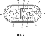
- a thermally responsive switch 1 is an airtight container configured of a metal housing 2 and a lid plate 3.
- the housing 2 is formed into a long-dome shape having an open end.
- the lid plate 3 is airtightly fixed to the open end of the housing 2 by welding or the like.
- Conductive terminal pins 4A, 4B made of metal are inserted into two through holes provided in the lid plate 3. These conductive terminal pins 4A, 4B are fixed by an electrically insulating filler such as glass. Thus, the conductive terminal pins 4A, 4B are airtightly fixed in an electrically insulated state.
- a fixed contact 6A is fixed, through a conductive fixed contact support 6B, to a portion of the conductive terminal pin 4A located inside the airtight container.
- a thermally responsive plate 9 configured of bimetal or tri-metal, for example, is fixed to the inner side of the housing 2 through a connecting body 10.
- the thermally responsive plate 9 is formed into a dish shape by drawing and has one end connected to an inner surface of the housing 2 through the connecting body 10.
- the thermally responsive plate 9 reverses its curving direction when it reaches a predetermined temperature.
- a movable contact 8 is fixed to a movable end which is the other end of the thermally responsive plate 9.
- the movable contact 8 moves away from the fixed contact 6A. This releases the connection between the movable contact 8 and the fixed contact 6A, and cuts off an electric circuit formed of: the conductive terminal pin 4B - a heater 7 - the lid plate 3 - the housing 2 - the connecting body 10 - the thermally responsive plate 9 - the movable contact 8 - the fixed contact 6A - the fixed contact support 6B - the conductive terminal pin 4A.
- the movable contact 8 is placed in contact with the fixed contact 6A and forms the above electric circuit.
- the movable contact 8 opens and closes the electric circuit by being driven by the thermally responsive plate 9 to come into contact with and separate from the fixed contact 6A.
- the heater 7 taking a three-dimensionally meandering shape as shown in FIG.4 , is manufactured by bending a strip-shaped heater forming material meandering as illustrated in FIG.5 with respect to predetermined references axes 7Ha and 7Hb serving as folding lines.
- the heater forming material shown in FIG.5 is obtained, for example, by blanking a planar metal plate having a predetermined resistivity.
- the heater 7 has meandering portions, and the meandering portions are bent.
- the heater 7 is configured of multiple heater units including a linear portion 7A being a linear heating element and a semicircular portion 7B being a semicircular heating element. Multiple heater units are alternately connected by joining the linear portion 7A of one heater unit to the semicircular portion 7B of another heater unit to form the heater 7.
- the heater 7 has multiple meandering portions 7C, 7D in which multiple linear portions 7A are provided adjacent to one another with the semicircular portion 7B interposed therebetween.
- the structure of the heater 7 adopts the meandering heating element so that a longer electric circuit can be obtained in a limited space.
- the meandering portions 7C, 7D are connected by a connecting portion 7E.
- the connecting portion 7E is a strip-shaped element extending in a straight line.
- the connection portion 7E may be configured as a meandering portion.
- fixing portions 7F, 7G are provided on the two end portions of the heater 7.
- the meandering portions 7C, 7D are bent twice with respect to a predetermined first reference axis 7Ha and a second reference axis 7Hb illustrated in FIG.5 .
- the first reference axis 7Ha and the second reference axis 7Hb are each an axis extending along a longitudinal direction of the housing 2 shaped like a long dome. Further, the first reference axis 7Ha is set so as to be located on the outer side of the second reference axis 7Hb as viewed in the width direction of the heater 7 and the second reference axis 7Hb is set so as to be located on the inner side of the first reference axis 7Ha as viewed in the width direction of the heater 7.
- the second reference axis 7Hb is set on the outer sides of the two ends of the connecting portion 7E so as to sandwich the connecting portion 7E and the first reference axis 7Ha is set further on the outer side of the second reference axis 7Hb.
- the first reference axis 7Ha and the second reference axis 7Hb extend in a direction perpendicular to the direction in which the linear portion 7A extends and the direction in which the connecting portion 7E connecting the meandering portions 7C, 7D extends.
- the linear portion 7A of the heater unit located in the portion facing the fixing portion 7F (the portion facing the conductive terminal pin 4B when mounted inside the airtight container) is shorter than the linear portions 7A of other heater units 7A.
- the linear portion 7A of the heater unit located in the portion facing the fixing portion 7F (the portion facing the conductive terminal pin 4B when mounted inside the airtight container) is shorter than the linear portions 7A of other heater units 7A.
- the meandering portions 7C, 7D are bent with respect to the first reference axis 7Ha and the second reference axis 7Hb such that a first surface of the two surfaces of the linear portion 7A faces the same first surface.
- the meandering portions 7C, 7D are bent 180 degrees at two locations, namely with respect to the first reference axis 7Ha and with respect to the second reference axis 7Hb.
- a predetermined gap is formed between opposing planes of the first surface of the same linear portion 7A, that is, between the surfaces located on the inner side in the bent state.
- the meandering portions 7C, 7D are configured such that the strip-shaped planar portions constituting the linear portions 7A face each other. Also, the meandering portions 7C, 7D are bent such that the linear portions 7A extend in the direction perpendicular to the connecting portion 7E.
- the heater 7 is arranged inside the airtight container such that the connecting portion 7E is parallel to the inner surface of the lid plate 3. Accordingly, the heater 7 is arranged inside the airtight container such that the linear portions 7A extend in a direction perpendicular to the inner surface of the lid plate 3.
- the heater 7 can be accommodated in a smaller space and the heater 7 having a longer overall length can be arranged inside a conventionalsized airtight container.
- the heater 7 having the meandering portions 7C, 7D bent in this manner is arranged inside the airtight container such that the linear portion 7A of one meandering portion 7C faces the linear portion 7A of the other meandering portion 7D.
- the heater 7 is arranged inside the airtight container such that the linear portion 7A of one meandering portion 7C is parallel to the linear portion 7A of the other meandering portion 7D.
- the heater 7 surrounds the periphery of the conductive terminal pin 4B with the fixing portion 7G - the meandering portion 7C - the connecting portion 7E - the meandering portion 7D - the fixing portion 7F. That is, the heater 7 is arranged around the conductive terminal pin 4B so as to form a spiral. Further, the heater 7 is arranged so that the meandering portions 7C, 7D oppose each other with the conductive terminal pin 4B interposed therebetween. Also, the heater 7 is arranged such that the meandering portions 7C, 7D are parallel to the inner surface of the lid plate 3.
- the heater 7 is also arranged such that the side surfaces on the outer sides of the meandering portions 7C, 7D are aligned with an inner peripheral surface of the housing 2.
- the fixing portion 7G being an end portion of the heater 7 on the circumferential edge side is fixed to the inner surface of the lid plate 3 by welding, for example.
- the fixing portion 7F being an end portion of the heater 7 on the center side is fixed to an end portion of the conductive terminal pin 4B inside the airtight container by welding, for example.
- the heater 7 is arranged inside the airtight container such that the connection portion 7E is on the thermally responsive plate 9 side, a bent portion closest to the connection portion 7E is on the lid plate 3 side, and the next bent portion is on the thermally responsive plate 9 side.
- the heater 7 when the heater 7 is arranged inside the airtight container, its area is larger on the thermally responsive plate 9 side than on the lid plate 3 side which is opposite of the thermally responsive plate 9 side.
- the meandering portions 7C, 7D are bent twice with respect to the first reference axis 7Ha and the second reference axis 7Hb extending in the longitudinal direction of the housing 2 so that each of the meandering portions 7C, 7D form multiple outer vertical portions 71, multiple inner vertical portions 72, and multiple middle vertical portions 73.
- the outer vertical portion 71 is located in the outer side of the first reference axis 7Ha and is vertical with respect to the inner surface of the lid plate 3.
- the inner vertical portion 72 is located in the inner side of the second reference axis 7Hb and is vertical with respect to the inner surface of the lid plate 3.
- the middle vertical portion 73 is located between the first reference axis 7Ha and the second reference axis 7Hb so as to be interposed between the outer vertical portion 71 and the inner vertical portion 72 and is vertical with respect to the inner surface of the lid plate 3.
- the middle vertical portions 73 formed in the heater 7 can be categorized into two types, namely, type A in which other middle vertical portion 73 exists on both widthwise end portions of the middle vertical portion 73 and type B in which other middle vertical portion 73 does not exist on one of the widthwise end portions of the middle vertical portion 73 as shown in FIG.6 .
- three type B middle vertical portions 73B are formed in a single heater 7; that is, one middle vertical portion 73B formed in immediate proximity of the fixing portion 7F and two middle vertical portions 73B formed on both ends of the connecting portion 7E.
- special creative efforts are put in to the shape of the middle vertical portion 73B formed in immediate proximity of the fixing portion 7F.
- FIG.7 illustrates a part of the heater 7 and in particular, the part near the fixing portion 7F.
- a narrow portion 74 serving as a fuse portion that melts more easily compared to other portions of the heater 7, is formed to the middle vertical portion 73B formed in immediate proximity of the fixing portion 7F.
- the narrow portion 74 is located at one of the two widthwise end portions of the middle vertical portion 73B in which other heating element does not exist and has a narrower width compared to the middle vertical portion 73B.
- the thermally responsive switch 1 is arranged inside the airtight container so that relatively wide space is secured in the side of the end portion where the narrow portion 74 is provided among the two end portions of the middle vertical portion 73B.
- the narrow portion 74 is provided so as to be shifted toward the end portion located in the free side of the middle vertical portion 73B where no other heating element exists (the end portion in the right side as viewed in FIG.8 ) as viewed in the width direction of the middle vertical portion 73B. That is, the narrow portion 74 is provided in a position shifted toward the free side of the middle vertical portion 73B relative to a center line CL as viewed in the width direction of the middle vertical portion 73B.
- a recess 75 is formed which caves in the shape of a circular arc toward the end portion located in the side where no other heating element exists.
- the shape of the recess 75 is not limited to a circular arc.
- the heater 7 is provided with a thin portion 76 between the fixing portion 7F which is an end portion connected to the conductive terminal pin 4B and the inner vertical portion 72 which faces the middle vertical portion 73B provided with the narrow portion 74.
- the width of the thin portion 76 is at least thinner than the width of the inner vertical portion 72.
- a vertical dimension H1 of the inner vertical portion 72 is shorter than a vertical dimension H2 of the middle vertical portion 73.
- the heater 7 may be configured so that the vertical dimension of the outer vertical portion 71 is shorter than the vertical dimension of the middle vertical portion 73 or the vertical dimensions of both the outer vertical portion 71 and the inner vertical portion 72 are shorter than the vertical dimension of the middle vertical portion 73. In other words, the heater 7 may be configured so that at least either of the outer vertical portion 71 and the inner vertical portion 72 is shorter than the middle vertical portion 73.
- the heating elements of the heater 7 are provided with meandering portions 7C, 7D formed of a strip-shaped metal plate.
- Each of the meandering portions 7C, 7D is bent twice with respect to the first reference axis 7Ha and the second reference axis 7Hb extending in the longitudinal direction of the housing 2.
- the meandering portions 7C, 7D are each provided with the outer vertical portion 71 disposed in the outer side of the first reference axis 7Ha so as to be perpendicular to the inner surface of the lid 3, the inner vertical portion 72 disposed in the inner side of the second reference axis 7Hb so as to be perpendicular to the inner surface of the lid 3, and the middle vertical portion 73 disposed between the first reference axis 7Ha and the second reference axis 7Hb and between the outer vertical portion 71 and the inner vertical portion 72 so as to be perpendicular to the inner surface of the lid 3.
- the middle vertical portion 73B provided in immediate proximity of the fixing portion 7F is provided with the narrow portion 74 being narrower than the width of the middle vertical portion 73B on the end portion located in the free side of the middle vertical portion 73B where no other heating element exists among the two widthwise end portions of the middle vertical portion 73B.
- the narrow portion 74 serving as the fusing portion is provided on the end portion located in the free side of the middle vertical portion 73B where no other heating element exists among the two widthwise end portions of the middle vertical portion 73B.
- Relatively wide space is provided beside the end portion in the free side of the middle vertical portion 73B.
- the heater 7 is provided with three type-B middle vertical portions 73B in which no other middle vertical portion 73 exists on one of the two widthwise end portions of the middle vertical portion 73.
- the two middle vertical portions 73B other than the middle vertical portion 73B located in immediate proximity of the fixing portion 7F are disposed near the thermally responsive plate 9.
- the narrow portion 74 having a relatively large heating value is formed at these two middle vertical portions 73B, heat transfer may occur in a concentrated manner between the heater 7 and the thermally responsive plate 9 and possibly affect the stability of operation.
- the narrow portion 74 is formed at the middle vertical portion 73B located most distant from the thermally responsive plate 9. It is thus, possible to prevent the operation of the switch from becoming unstable by the formation of the narrow portion 74.
- the heater 7 forms meandering portions 7C, 7D configured of meandering strip-shaped metal plates.
- the meandering portions 7C, 7D are bent twice with respect to two reference axes 7Ha and 7Hb to provide a complicated shape. According to such structure, heat tends to accumulate especially in the middle vertical portion 73 disposed between the outer vertical portion 71 and the inner vertical portion 72.
- the heater 7 is configured so that the vertical dimension of the inner vertical portion 72 is shorter than the vertical dimension of the middle vertical portion 73. It is thus, possible to reduce the area of the inner vertical portion 72 facing the middle vertical portion 73. In other words, it is possible to increase the area of the middle vertical portion 73 for releasing heat. As a result, it is possible to improve heat dissipation from the middle vertical portion 73 and prevent excessive temperature elevation at the middle vertical portion 73 to thereby provide a homogenous temperature distribution.
- the heater 7 is configured so that thin portion 76 thinner than the inner vertical portion 72 is provided between the fixing portion 7F connected to the conductive terminal pin 4B and the inner vertical portion 72. According to such configuration, it is possible to prevent the temperature of the inner vertical portion 72 from becoming too low by the heat escaping towards the conductive terminal pin 4B side from the fixing portion 7F.
- the heater 7 is required to generate amount of heat which is correlated with the size of current flowing through the heater 7. When heat escapes towards the conductive terminal pin 4B side from the fixing portion 7F, the temperature of the inner vertical portion 72 may become too low.
- the narrow portion 74 exhibiting relatively large heating value is located close to the fixing portion 7F in the present embodiment, it may not be possible to obtain the desired fusing performance when subjected to overcurrent.
- the thin portion 76 is provided to increase the heating value in the vicinity of the fixing portion 7F. As a result, heat at the inner vertical portion 72 including the narrow portion 74 does not easily escape toward the conductive terminal pin 4B side. It is thus, possible to maintain the capacity of the heater 7 to generate amount of heat which is correlated with the size of current flowing through the heater 7.
- the present invention is not limited to the embodiment described above but may be modified or expanded within the gist of the invention.
- the number of meandering portions provided to the heater is not limited to two but may be increased or decreased as required.
Landscapes
- Engineering & Computer Science (AREA)
- Mechanical Engineering (AREA)
- General Engineering & Computer Science (AREA)
- Physics & Mathematics (AREA)
- Thermal Sciences (AREA)
- Thermally Actuated Switches (AREA)
- Resistance Heating (AREA)
Applications Claiming Priority (1)
| Application Number | Priority Date | Filing Date | Title |
|---|---|---|---|
| PCT/JP2014/084082 WO2016103349A1 (ja) | 2014-12-24 | 2014-12-24 | 熱応動開閉器 |
Publications (2)
| Publication Number | Publication Date |
|---|---|
| EP3240006A1 true EP3240006A1 (de) | 2017-11-01 |
| EP3240006A4 EP3240006A4 (de) | 2018-08-08 |
Family
ID=56149449
Family Applications (1)
| Application Number | Title | Priority Date | Filing Date |
|---|---|---|---|
| EP14908957.5A Withdrawn EP3240006A4 (de) | 2014-12-24 | 2014-12-24 | Thermischer reaktionsschalter |
Country Status (10)
| Country | Link |
|---|---|
| US (1) | US20170352510A1 (de) |
| EP (1) | EP3240006A4 (de) |
| JP (1) | JP6413203B2 (de) |
| KR (1) | KR101939006B1 (de) |
| CN (1) | CN107112165A (de) |
| BR (1) | BR112017013061A2 (de) |
| MX (1) | MX2017008214A (de) |
| PH (1) | PH12017550032A1 (de) |
| SG (1) | SG11201705051XA (de) |
| WO (1) | WO2016103349A1 (de) |
Families Citing this family (1)
| Publication number | Priority date | Publication date | Assignee | Title |
|---|---|---|---|---|
| CN112447444A (zh) * | 2020-12-16 | 2021-03-05 | 江苏常荣电器股份有限公司 | 一种热动开关的发热丝 |
Family Cites Families (14)
| Publication number | Priority date | Publication date | Assignee | Title |
|---|---|---|---|---|
| US5221915A (en) * | 1991-05-24 | 1993-06-22 | Matsushita Electric Industrial Co., Ltd. | Thermal protector |
| JP3828476B2 (ja) * | 2002-10-15 | 2006-10-04 | 株式会社センサータ・テクノロジーズジャパン | 無通電式密閉型モータプロテクタ |
| JP2005240596A (ja) * | 2004-02-24 | 2005-09-08 | Ubukata Industries Co Ltd | 電動圧縮機用保護装置 |
| JP2007115610A (ja) * | 2005-10-24 | 2007-05-10 | Sankei Giken:Kk | 面状発熱体 |
| MY158650A (en) * | 2006-08-10 | 2016-10-31 | Ubukata Ind Co Ltd | Thermally responsive switch |
| BRPI0716646B1 (pt) * | 2006-08-10 | 2018-07-31 | Ubukata Industries Co., Ltd. | Comutador de resposta térmica |
| US20090159354A1 (en) * | 2007-12-25 | 2009-06-25 | Wenfeng Jiang | Battery system having interconnected battery packs each having multiple electrochemical storage cells |
| CA2715130C (en) * | 2008-02-08 | 2015-06-02 | Ubukata Industries Co., Ltd. | Thermally responsive switch |
| EP2282320A1 (de) * | 2009-08-01 | 2011-02-09 | Limitor GmbH | Bimetall-Schnappscheibe |
| US9169635B2 (en) * | 2012-08-30 | 2015-10-27 | Ronald Andrews | Apparatus to tie forms to existing structures |
| JP6103180B2 (ja) * | 2012-09-14 | 2017-03-29 | 株式会社生方製作所 | 密閉形電動圧縮機用熱応動開閉器 |
| KR101779469B1 (ko) * | 2013-01-21 | 2017-09-18 | 가부시키가이샤 우부카타 세이사쿠쇼 | 열 응동 스위치 및 그 제조방법 그리고 가동 접점의 높이 조정장치 |
| CN203150476U (zh) * | 2013-03-12 | 2013-08-21 | 株式会社生方制作所 | 一种热敏开关 |
| CN106663565B (zh) * | 2014-05-23 | 2019-06-11 | 株式会社生方制作所 | 热动开关 |
-
2014
- 2014-12-24 EP EP14908957.5A patent/EP3240006A4/de not_active Withdrawn
- 2014-12-24 CN CN201480084188.0A patent/CN107112165A/zh active Pending
- 2014-12-24 MX MX2017008214A patent/MX2017008214A/es unknown
- 2014-12-24 WO PCT/JP2014/084082 patent/WO2016103349A1/ja not_active Ceased
- 2014-12-24 BR BR112017013061-0A patent/BR112017013061A2/pt not_active Application Discontinuation
- 2014-12-24 US US15/539,036 patent/US20170352510A1/en not_active Abandoned
- 2014-12-24 JP JP2016565716A patent/JP6413203B2/ja not_active Expired - Fee Related
- 2014-12-24 SG SG11201705051XA patent/SG11201705051XA/en unknown
- 2014-12-24 KR KR1020177017685A patent/KR101939006B1/ko not_active Expired - Fee Related
-
2017
- 2017-06-23 PH PH12017550032A patent/PH12017550032A1/en unknown
Also Published As
| Publication number | Publication date |
|---|---|
| PH12017550032A1 (en) | 2018-01-15 |
| JP6413203B2 (ja) | 2018-10-31 |
| JPWO2016103349A1 (ja) | 2017-10-05 |
| US20170352510A1 (en) | 2017-12-07 |
| MX2017008214A (es) | 2017-10-06 |
| EP3240006A4 (de) | 2018-08-08 |
| SG11201705051XA (en) | 2017-07-28 |
| WO2016103349A1 (ja) | 2016-06-30 |
| CN107112165A (zh) | 2017-08-29 |
| KR101939006B1 (ko) | 2019-01-15 |
| KR20170086646A (ko) | 2017-07-26 |
| BR112017013061A2 (pt) | 2018-01-02 |
Similar Documents
| Publication | Publication Date | Title |
|---|---|---|
| JP3828476B2 (ja) | 無通電式密閉型モータプロテクタ | |
| KR101914186B1 (ko) | 접점 구조 | |
| JP5886609B2 (ja) | ブレーカー及びそれを備えた安全回路並びに2次電池パック | |
| JP6188343B2 (ja) | ブレーカー及びそれを備えた安全回路並びに2次電池回路 | |
| EP3240006A1 (de) | Thermischer reaktionsschalter | |
| JP5941301B2 (ja) | ブレーカー及びそれを備えた安全回路並びに2次電池 | |
| JP2012160317A (ja) | ブレーカー | |
| JP6457810B2 (ja) | ブレーカー及びそれを備えた安全回路並びに2次電池回路。 | |
| JP6592299B2 (ja) | ブレーカー及びそれを備えた安全回路並びに2次電池回路。 | |
| US10056211B2 (en) | Heat-reactive switch | |
| JP6204721B2 (ja) | ブレーカー及びそれを備えた安全回路並びに2次電池回路 | |
| JP2018206732A (ja) | ブレーカー | |
| JP7406279B2 (ja) | モータプロテクタ | |
| JP2013020864A (ja) | サーマルプロテクター | |
| JP6644237B2 (ja) | 熱応動開閉器 | |
| CN112447444A (zh) | 一种热动开关的发热丝 | |
| US10347450B2 (en) | Thermally actuated switch and forming dies | |
| JP2014120379A (ja) | ブレーカー | |
| KR101243712B1 (ko) | 과부하 보호장치 | |
| JP2019075354A (ja) | 電流遮断装置、安全回路及び2次電池パック。 | |
| KR20080047720A (ko) | 모터의 일체형 과열방지장치 |
Legal Events
| Date | Code | Title | Description |
|---|---|---|---|
| PUAI | Public reference made under article 153(3) epc to a published international application that has entered the european phase |
Free format text: ORIGINAL CODE: 0009012 |
|
| 17P | Request for examination filed |
Effective date: 20170704 |
|
| AK | Designated contracting states |
Kind code of ref document: A1 Designated state(s): AL AT BE BG CH CY CZ DE DK EE ES FI FR GB GR HR HU IE IS IT LI LT LU LV MC MK MT NL NO PL PT RO RS SE SI SK SM TR |
|
| AX | Request for extension of the european patent |
Extension state: BA ME |
|
| DAX | Request for extension of the european patent (deleted) | ||
| RIN1 | Information on inventor provided before grant (corrected) |
Inventor name: YAMAGUCHI, YOSHIO |
|
| A4 | Supplementary search report drawn up and despatched |
Effective date: 20180706 |
|
| RIC1 | Information provided on ipc code assigned before grant |
Ipc: F04B 39/00 20060101ALI20180702BHEP Ipc: F04C 29/00 20060101ALI20180702BHEP Ipc: H01H 37/54 20060101ALI20180702BHEP Ipc: H01H 37/14 20060101AFI20180702BHEP |
|
| STAA | Information on the status of an ep patent application or granted ep patent |
Free format text: STATUS: THE APPLICATION HAS BEEN WITHDRAWN |
|
| 18W | Application withdrawn |
Effective date: 20190212 |
|
| RIC1 | Information provided on ipc code assigned before grant |
Ipc: H01H 37/54 20060101ALI20190208BHEP Ipc: H01H 37/14 20060101AFI20190208BHEP Ipc: F04C 29/00 20060101ALI20190208BHEP Ipc: F04B 39/00 20060101ALI20190208BHEP |