EP3240073B1 - Vorrichtung und verfahren zur bestimmung des zustands einer brennstoffbatterie - Google Patents
Vorrichtung und verfahren zur bestimmung des zustands einer brennstoffbatterie Download PDFInfo
- Publication number
- EP3240073B1 EP3240073B1 EP14909066.4A EP14909066A EP3240073B1 EP 3240073 B1 EP3240073 B1 EP 3240073B1 EP 14909066 A EP14909066 A EP 14909066A EP 3240073 B1 EP3240073 B1 EP 3240073B1
- Authority
- EP
- European Patent Office
- Prior art keywords
- impedance
- fuel cell
- frequency
- frequency band
- anode electrode
- Prior art date
- Legal status (The legal status is an assumption and is not a legal conclusion. Google has not performed a legal analysis and makes no representation as to the accuracy of the status listed.)
- Not-in-force
Links
- 239000000446 fuel Substances 0.000 title claims description 173
- 238000001514 detection method Methods 0.000 title claims description 28
- 238000000034 method Methods 0.000 title description 18
- 238000006243 chemical reaction Methods 0.000 claims description 90
- 239000012528 membrane Substances 0.000 claims description 88
- 239000003792 electrolyte Substances 0.000 claims description 86
- 230000004044 response Effects 0.000 claims description 77
- 238000005259 measurement Methods 0.000 claims description 25
- 238000002847 impedance measurement Methods 0.000 claims description 16
- 238000004364 calculation method Methods 0.000 claims description 13
- 230000004043 responsiveness Effects 0.000 claims description 12
- 239000007789 gas Substances 0.000 description 125
- 238000009792 diffusion process Methods 0.000 description 14
- 238000010926 purge Methods 0.000 description 13
- 238000010586 diagram Methods 0.000 description 12
- 239000003054 catalyst Substances 0.000 description 10
- 238000007599 discharging Methods 0.000 description 9
- 230000003647 oxidation Effects 0.000 description 7
- 238000007254 oxidation reaction Methods 0.000 description 7
- 238000006722 reduction reaction Methods 0.000 description 7
- 230000008859 change Effects 0.000 description 5
- 238000010248 power generation Methods 0.000 description 5
- 230000006870 function Effects 0.000 description 4
- 239000000463 material Substances 0.000 description 4
- BASFCYQUMIYNBI-UHFFFAOYSA-N platinum Chemical compound [Pt] BASFCYQUMIYNBI-UHFFFAOYSA-N 0.000 description 4
- XLYOFNOQVPJJNP-UHFFFAOYSA-N water Substances O XLYOFNOQVPJJNP-UHFFFAOYSA-N 0.000 description 4
- UFHFLCQGNIYNRP-UHFFFAOYSA-N Hydrogen Chemical compound [H][H] UFHFLCQGNIYNRP-UHFFFAOYSA-N 0.000 description 3
- NBIIXXVUZAFLBC-UHFFFAOYSA-N Phosphoric acid Chemical compound OP(O)(O)=O NBIIXXVUZAFLBC-UHFFFAOYSA-N 0.000 description 3
- QVGXLLKOCUKJST-UHFFFAOYSA-N atomic oxygen Chemical compound [O] QVGXLLKOCUKJST-UHFFFAOYSA-N 0.000 description 3
- 238000003411 electrode reaction Methods 0.000 description 3
- 238000002474 experimental method Methods 0.000 description 3
- 239000000203 mixture Substances 0.000 description 3
- 239000001301 oxygen Substances 0.000 description 3
- 229910052760 oxygen Inorganic materials 0.000 description 3
- 238000012545 processing Methods 0.000 description 3
- IJGRMHOSHXDMSA-UHFFFAOYSA-N Atomic nitrogen Chemical compound N#N IJGRMHOSHXDMSA-UHFFFAOYSA-N 0.000 description 2
- 230000007423 decrease Effects 0.000 description 2
- 230000001419 dependent effect Effects 0.000 description 2
- 230000000694 effects Effects 0.000 description 2
- 239000001257 hydrogen Substances 0.000 description 2
- 229910052739 hydrogen Inorganic materials 0.000 description 2
- 229920000554 ionomer Polymers 0.000 description 2
- 229910052697 platinum Inorganic materials 0.000 description 2
- 230000001172 regenerating effect Effects 0.000 description 2
- 239000004065 semiconductor Substances 0.000 description 2
- OKTJSMMVPCPJKN-UHFFFAOYSA-N Carbon Chemical compound [C] OKTJSMMVPCPJKN-UHFFFAOYSA-N 0.000 description 1
- 229910000147 aluminium phosphate Inorganic materials 0.000 description 1
- 230000002457 bidirectional effect Effects 0.000 description 1
- 229910052799 carbon Inorganic materials 0.000 description 1
- 239000006229 carbon black Substances 0.000 description 1
- 239000002131 composite material Substances 0.000 description 1
- 230000003247 decreasing effect Effects 0.000 description 1
- 230000000994 depressogenic effect Effects 0.000 description 1
- 230000006866 deterioration Effects 0.000 description 1
- 239000000428 dust Substances 0.000 description 1
- 230000005284 excitation Effects 0.000 description 1
- 239000004744 fabric Substances 0.000 description 1
- XLYOFNOQVPJJNP-ZSJDYOACSA-N heavy water Substances [2H]O[2H] XLYOFNOQVPJJNP-ZSJDYOACSA-N 0.000 description 1
- 239000012535 impurity Substances 0.000 description 1
- 239000003014 ion exchange membrane Substances 0.000 description 1
- 238000010030 laminating Methods 0.000 description 1
- 239000011159 matrix material Substances 0.000 description 1
- 238000012806 monitoring device Methods 0.000 description 1
- 238000012544 monitoring process Methods 0.000 description 1
- 229910052757 nitrogen Inorganic materials 0.000 description 1
- 239000007800 oxidant agent Substances 0.000 description 1
- 230000001590 oxidative effect Effects 0.000 description 1
- 239000002245 particle Substances 0.000 description 1
- 230000008569 process Effects 0.000 description 1
- 239000012495 reaction gas Substances 0.000 description 1
- 238000011084 recovery Methods 0.000 description 1
- 230000001360 synchronised effect Effects 0.000 description 1
- 230000002123 temporal effect Effects 0.000 description 1
Images





Classifications
-
- H—ELECTRICITY
- H01—ELECTRIC ELEMENTS
- H01M—PROCESSES OR MEANS, e.g. BATTERIES, FOR THE DIRECT CONVERSION OF CHEMICAL ENERGY INTO ELECTRICAL ENERGY
- H01M8/00—Fuel cells; Manufacture thereof
- H01M8/04—Auxiliary arrangements, e.g. for control of pressure or for circulation of fluids
- H01M8/04082—Arrangements for control of reactant parameters, e.g. pressure or concentration
- H01M8/04089—Arrangements for control of reactant parameters, e.g. pressure or concentration of gaseous reactants
- H01M8/04119—Arrangements for control of reactant parameters, e.g. pressure or concentration of gaseous reactants with simultaneous supply or evacuation of electrolyte; Humidifying or dehumidifying
-
- H—ELECTRICITY
- H01—ELECTRIC ELEMENTS
- H01M—PROCESSES OR MEANS, e.g. BATTERIES, FOR THE DIRECT CONVERSION OF CHEMICAL ENERGY INTO ELECTRICAL ENERGY
- H01M8/00—Fuel cells; Manufacture thereof
- H01M8/04—Auxiliary arrangements, e.g. for control of pressure or for circulation of fluids
- H01M8/04298—Processes for controlling fuel cells or fuel cell systems
- H01M8/04313—Processes for controlling fuel cells or fuel cell systems characterised by the detection or assessment of variables; characterised by the detection or assessment of failure or abnormal function
- H01M8/0438—Pressure; Ambient pressure; Flow
- H01M8/04388—Pressure; Ambient pressure; Flow of anode reactants at the inlet or inside the fuel cell
-
- H—ELECTRICITY
- H01—ELECTRIC ELEMENTS
- H01M—PROCESSES OR MEANS, e.g. BATTERIES, FOR THE DIRECT CONVERSION OF CHEMICAL ENERGY INTO ELECTRICAL ENERGY
- H01M8/00—Fuel cells; Manufacture thereof
- H01M8/04—Auxiliary arrangements, e.g. for control of pressure or for circulation of fluids
- H01M8/04298—Processes for controlling fuel cells or fuel cell systems
- H01M8/04313—Processes for controlling fuel cells or fuel cell systems characterised by the detection or assessment of variables; characterised by the detection or assessment of failure or abnormal function
- H01M8/0438—Pressure; Ambient pressure; Flow
- H01M8/04395—Pressure; Ambient pressure; Flow of cathode reactants at the inlet or inside the fuel cell
-
- H—ELECTRICITY
- H01—ELECTRIC ELEMENTS
- H01M—PROCESSES OR MEANS, e.g. BATTERIES, FOR THE DIRECT CONVERSION OF CHEMICAL ENERGY INTO ELECTRICAL ENERGY
- H01M8/00—Fuel cells; Manufacture thereof
- H01M8/04—Auxiliary arrangements, e.g. for control of pressure or for circulation of fluids
- H01M8/04298—Processes for controlling fuel cells or fuel cell systems
- H01M8/04313—Processes for controlling fuel cells or fuel cell systems characterised by the detection or assessment of variables; characterised by the detection or assessment of failure or abnormal function
- H01M8/04537—Electric variables
- H01M8/04544—Voltage
- H01M8/04552—Voltage of the individual fuel cell
-
- H—ELECTRICITY
- H01—ELECTRIC ELEMENTS
- H01M—PROCESSES OR MEANS, e.g. BATTERIES, FOR THE DIRECT CONVERSION OF CHEMICAL ENERGY INTO ELECTRICAL ENERGY
- H01M8/00—Fuel cells; Manufacture thereof
- H01M8/04—Auxiliary arrangements, e.g. for control of pressure or for circulation of fluids
- H01M8/04298—Processes for controlling fuel cells or fuel cell systems
- H01M8/04313—Processes for controlling fuel cells or fuel cell systems characterised by the detection or assessment of variables; characterised by the detection or assessment of failure or abnormal function
- H01M8/04537—Electric variables
- H01M8/04574—Current
- H01M8/04582—Current of the individual fuel cell
-
- H—ELECTRICITY
- H01—ELECTRIC ELEMENTS
- H01M—PROCESSES OR MEANS, e.g. BATTERIES, FOR THE DIRECT CONVERSION OF CHEMICAL ENERGY INTO ELECTRICAL ENERGY
- H01M8/00—Fuel cells; Manufacture thereof
- H01M8/04—Auxiliary arrangements, e.g. for control of pressure or for circulation of fluids
- H01M8/04298—Processes for controlling fuel cells or fuel cell systems
- H01M8/04313—Processes for controlling fuel cells or fuel cell systems characterised by the detection or assessment of variables; characterised by the detection or assessment of failure or abnormal function
- H01M8/04537—Electric variables
- H01M8/04634—Other electric variables, e.g. resistance or impedance
- H01M8/04641—Other electric variables, e.g. resistance or impedance of the individual fuel cell
-
- Y—GENERAL TAGGING OF NEW TECHNOLOGICAL DEVELOPMENTS; GENERAL TAGGING OF CROSS-SECTIONAL TECHNOLOGIES SPANNING OVER SEVERAL SECTIONS OF THE IPC; TECHNICAL SUBJECTS COVERED BY FORMER USPC CROSS-REFERENCE ART COLLECTIONS [XRACs] AND DIGESTS
- Y02—TECHNOLOGIES OR APPLICATIONS FOR MITIGATION OR ADAPTATION AGAINST CLIMATE CHANGE
- Y02E—REDUCTION OF GREENHOUSE GAS [GHG] EMISSIONS, RELATED TO ENERGY GENERATION, TRANSMISSION OR DISTRIBUTION
- Y02E60/00—Enabling technologies; Technologies with a potential or indirect contribution to GHG emissions mitigation
- Y02E60/30—Hydrogen technology
- Y02E60/50—Fuel cells
Definitions
- This invention relates to state detection device and method for fuel cell.
- a state detection device for fuel cell which measures a voltage value and an impedance value of a fuel cell and detects an internal state of the fuel cell on the basis of these values.
- Japanese Patent No. 4640661 it is proposed in Japanese Patent No. 4640661 to calculate a first impedance in a first frequency region corresponding to an electrolyte membrane resistance and a second impedance in a second frequency region corresponding to the sum of the electrolyte membrane resistance and a catalyst layer resistance and lower than the first frequency region and calculate a water content of a catalyst layer on the basis of a differential impedance between the second and first impedances.
- JP2005-285614A acquire complex impedances corresponding to a frequency Fi at an intersection with a real axis of a complex impedance curve (Cole-Cole plot) of a fuel cell, a frequency F2 in a first region expressing a reaction resistance (reaction resistance of a cathode electrode) when oxygen reacts and a frequency F3 in a second region expressing a resistance concerning oxygen diffusion and obtain an internal resistance value from the obtained complex impedances.
- US 2011/269046 A1 relates to a method for determining the dryness in a fuel cell wherein the water content a catalyst layer is obtained using a differential impedance measurement.
- JP 2014/053182 A relates to fuel cell diagnostic apparatus diagnosing the diffusion state of a reaction gas inside a fuel cell. For this purpose, the membrane resistance and the diffusion impedance re obtained from the cell's impedance characteristics.
- US 2014/0295302 A1 relates to a fuel cell monitoring device, wherein an impedance is measured at different frequencies and, based thereon, a proton resistance and a gas reaction resistance are determined.
- the present invention was developed, focusing on such a problem, and aims to provide a state detection device and method for fuel cell capable of individually detecting internal state quantities such as state quantities of an anode electrode and those of a cathode electrode in a fuel cell.
- the present invention provides a state detection device for a fuel cell for generating power upon receiving a supply of anode gas and cathode gas. More specifically, the state detection device includes an impedance acquisition unit configured to acquire a high frequency impedance based on a frequency selected from a high frequency band and a low frequency impedance based on a frequency selected from a low frequency band, the high frequency band including a frequency band which shows responsiveness at least to a state quantity of an anode electrode, the low frequency band including a frequency band which shows responsiveness at least to a state quantity of a cathode electrode, and an internal state quantity estimation unit configured to estimate each of the state quantity of the anode electrode and the state quantity of the cathode electrode by combining the acquired high frequency impedance and low frequency impedance, the state quantity of the anode electrode and the state quantity of the cathode electrode serving as internal states of the fuel cell.
- an impedance acquisition unit configured to acquire a high frequency impedance based on a frequency selected from
- a fuel cell is configured such that an electrolyte membrane is sandwiched by an anode electrode serving as a fuel electrode and a cathode electrode serving as an oxidant electrode.
- the fuel cell generates power using anode gas containing hydrogen and supplied to the anode electrode and cathode gas containing oxygen and supplied to the cathode electrode. Electrode reactions which proceed in both anode and cathode electrodes are as follows.
- Anode electrode 2H 2 ⁇ 4H + +4e ...
- Cathode electrode 4H + +4e+O 2 ⁇ 2H 2 O ...
- FIGS. 1 and 2 are views showing the configuration of a fuel cell 10 according to one embodiment of the present invention.
- FIG. 1 is a perspective view of the fuel cell 10.
- FIG. 2 is a sectional view along II-II of the fuel cell 10 of FIG. 1 .
- the fuel cell 10 includes a membrane electrode assembly (MEA) 11, and an anode separator 12 and a cathode separator 13 arranged to sandwich the MEA 11.
- MEA membrane electrode assembly
- the MEA 11 is composed of an electrolyte membrane 111, an anode electrode 112 and a cathode electrode 113.
- the MEA 11 includes the anode electrode 112 on one surface side of the electrolyte membrane 111 and the cathode electrode 113 on the other surface side.
- the electrolyte membrane 111 is a proton conductive ion exchange membrane formed of fluororesin.
- the electrolyte membrane 111 exhibits good electrical conductivity in a wet state. It should be noted that another material such as a material having a phosphoric acid (H 3 PO 4 ) impregnated in a predetermined matrix may be used according to a possible response of a fuel cell.
- H 3 PO 4 phosphoric acid
- the anode electrode 112 includes a catalyst layer 112A and a gas diffusion layer 112B.
- the catalyst layer 112A is a member formed of platinum or carbon black particles carrying platinum or the like and provided in contact with the electrolyte membrane 111.
- the gas diffusion layer 112B is provided on an outer side of the catalyst layer 112A.
- the gas diffusion layer 112B is a member formed of carbon cloth having gas diffusion property and electrical conductivity and provided in contact with the catalyst layer 112A and the anode separator 12.
- the cathode electrode 113 also includes a catalyst layer 113A and a gas diffusion layer 113B.
- the catalyst layer 113A is arranged between the electrolyte membrane 111 and the gas diffusion layer 113B and the gas diffusion layer 113B is arranged between the catalyst layer 113A and the cathode separator 13.
- the anode separator 12 is arranged on an outer side of the gas diffusion layer 112B.
- the anode separator 12 includes a plurality of anode gas flow passages 121 for supplying anode gas (hydrogen gas) to the anode electrode 112.
- the anode gas flow passages 121 are formed as groove-like passages.
- the cathode separator 13 is arranged on an outer side of the gas diffusion layer 113B.
- the cathode separator 13 includes a plurality of cathode gas flow passages 131 for supplying cathode gas (air) to the cathode electrode 113.
- the cathode gas flow passages 131 are formed as groove-like passages.
- the anode separator 12 and the cathode separator 13 are so configured that the anode gas flowing in the anode gas flow passages 121 and the cathode gas flowing in the cathode gas flow passages 131 flow in directions opposite to each other. It should be noted that the anode separator 12 and the cathode separator 13 may be so configured that these gases flow in the same direction.
- a fuel cell stack in which several hundreds of fuel cells 10 are laminated is used since required power is large. Power for driving the vehicle is taken out by configuring a fuel cell system for supplying anode gas and cathode gas to the fuel cell stack. It should be noted that although an impedance measurement to be described later is conducted for each fuel cell stack in which the fuel cells 10 are laminated in the present embodiment, the impedance measurement may be conducted for each fuel cell 10 or for each part (e.g. several tens of cells) of the fuel cell stack.
- an anode electrode, a cathode electrode and an electrolyte membrane serving as sums are configured by arranging the anode electrodes 112, the cathode electrodes 113 and the electrolyte membranes 111 of a plurality of the fuel cells 10 in series.
- these anode electrode, cathode electrode and electrolyte membrane serving as the sums are also denoted by the same reference signs as the anode electrode 112, the cathode electrode 113 and the electrolyte membrane 111 of the single cell.
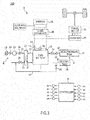
- FIG. 3 is a schematic diagram of a fuel cell system 100 according to one embodiment of the present invention.
- the fuel cell system 100 includes a fuel cell 1, a cathode gas supplying/discharging device 2, an anode gas supplying/discharging device 3, a power system 5 and a controller 6.
- the fuel cell 1 is a laminated battery formed by laminating a plurality of fuel cells 10 (unit cells) as described above.
- the fuel cell 1 generates power necessary to drive a vehicle upon receiving the supply of the anode gas and the cathode gas.
- the fuel cell 1 includes an anode electrode side terminal 1A and a cathode electrode side terminal 1B as output terminals for taking out power.
- the cathode gas supplying/discharging device 2 supplies the cathode gas to the fuel cell 1 and discharges cathode off-gas discharged from the fuel cell 1 to outside.
- the cathode gas supplying/discharging device 2 includes a cathode gas supply passage 21, a cathode gas discharge passage 22, a filter 23, an air flow sensor 24, a cathode compressor 25, a cathode pressure sensor 26, a water recovery device (WRD) 27 and a cathode pressure control valve 28.
- the cathode gas supply passage 21 is a passage in which the cathode gas to be supplied to the fuel cell 1 flows. One end of the cathode gas supply passage 21 is connected to the filter 23 and the other end is connected to a cathode gas inlet part of the fuel cell 1.
- the cathode gas discharge passage 22 is a passage in which the cathode off-gas discharged from the fuel cell 1 flows. One end of the cathode gas discharge passage 22 is connected to a cathode gas outlet part of the fuel cell 1 and the other end is formed as an opening end.
- the cathode off-gas is mixture gas containing the cathode gas, steam produced by the electrode reaction and the like.
- the filter 23 is a member for removing dust, dirt and the like contained in the cathode gas to be taken into the cathode gas supply passage 21.
- the cathode compressor 25 is provided downstream of the filter 23 in the cathode gas supply passage 21.
- the cathode compressor 25 supplies the cathode gas in the cathode gas supply passage 21 to the fuel cell 1 by feeding the cathode gas under pressure.
- the air flow sensor 24 is provided between the filter 23 and the cathode compressor 25 in the cathode gas supply passage 21.
- the air flow sensor 24 detects a flow rate of the cathode gas to be supplied to the fuel cell 1.
- the cathode pressure sensor 26 is provided between the cathode compressor 25 and the WRD 27 in the cathode gas supply passage 21.
- the cathode pressure sensor 26 detects a pressure of the cathode gas to be supplied to the fuel cell 1.
- the cathode gas pressure detected by the cathode pressure sensor 26 represents a pressure of an entire cathode system including the cathode gas flow passages of the fuel cell 1 and the like.
- the WRD 27 is connected over the cathode gas supply passage 21 and the cathode gas discharge passage 22.
- the WRD 27 is a device for recovering moisture in the cathode off-gas flowing in the cathode gas discharge passage 22 and humidifying the cathode gas flowing in the cathode gas supply passage 21 with that recovered moisture.
- the cathode pressure control valve 28 is provided downstream of the WRD 27 in the cathode gas discharge passage 22.
- the cathode pressure control valve 28 is controlled to open and close by the controller 6 and adjusts the pressure of the cathode gas to be supplied to the fuel cell 1.
- the anode gas supplying/discharging device 3 supplies the anode gas to the fuel cell 1 and discharges anode off-gas discharged from the fuel cell 1 to the cathode gas discharge passage 22.
- the anode gas supplying/discharging device 3 includes a high-pressure tank 31, an anode gas supply passage 32, an anode pressure control valve 33, an anode pressure sensor 34, an anode gas discharge passage 35, a buffer tank 36, a purge passage 37 and a purge valve 38.
- the high-pressure tank 31 is a container for storing the anode gas to be supplied to the fuel cell 1 in a high-pressure state.
- the anode gas supply passage 32 is a passage for supplying the anode gas discharged from the high-pressure tank 31 to the fuel cell 1.
- One end of the anode gas supply passage 32 is connected to the high-pressure tank 31 and the other end is connected to an anode gas inlet part of the fuel cell 1.
- the anode pressure control valve 33 is provided downstream of the high-pressure tank 31 in the anode gas supply passage 32.
- the anode pressure control valve 33 is controlled to open and close by the controller 6 and adjusts the pressure of the anode gas to be supplied to the fuel cell 1.
- the anode pressure sensor 34 is provided downstream of the anode pressure control valve 33 in the anode gas supply passage 32.
- the anode pressure sensor 34 detects a pressure of the anode gas to be supplied to the fuel cell 1.
- the anode gas pressure detected by the anode pressure sensor 34 represents a pressure of an entire anode system including the buffer tank 36, the anode gas flow passages of the fuel cell 1 and the like.
- the anode gas discharge passage 35 is a passage in which the anode off-gas discharged from the fuel cell 1 flows. One end of the anode gas discharge passage 35 is connected to an anode gas outlet part of the fuel cell 1 and the other end is connected to the buffer tank 36.
- the anode off-gas contains the anode gas not used in the electrode reaction, impurity gas such as nitrogen having leaked from the cathode gas flow passages 131 to the anode gas flow passages 121, moisture and the like.
- the buffer tank 36 is a container for temporarily storing the anode off-gas flowing from the anode gas discharge passage 35.
- the anode off-gas pooled in the buffer tank 36 is discharged to the cathode gas discharge passage 22 through the purge passage 37 when the purge valve 38 is opened.
- the purge passage 37 is a passage for discharging the anode off-gas. One end of the purge passage 37 is connected to the anode gas discharge passage 35 and the other end is connected to a part of the cathode gas discharge passage 22 downstream of the cathode pressure control valve 28.
- the purge valve 38 is provided in the purge passage 37.
- the purge valve 38 is controlled to open and close by the controller 6 and controls a purge flow rate of the anode off-gas discharged from the anode gas discharge passage 35 to the cathode gas discharge passage 22.
- anode off-gas When a purge control is executed to open the purge valve 38, the anode off-gas is discharged to outside through the purge passage 37 and the cathode gas discharge passage 22. At this time, the anode off-gas is mixed with the cathode off-gas in the cathode gas discharge passage 22.
- an anode gas concentration (hydrogen concentration) in the mixture gas is set at a value not larger than a discharge allowable concentration.
- the power system 5 includes a current sensor 51, a voltage sensor 52, a travel motor 53, an inverter 54, a battery 55 and a DC/DC converter 56.
- the current sensor 51 detects an output current extracted from the fuel cell 1.
- the voltage sensor 52 detects an output voltage of the fuel cell 1, i.e. an inter-terminal voltage between the anode electrode side terminal 1A and the cathode electrode side terminal 1B.
- the voltage sensor 52 may be configured to detect a voltage of each fuel cell 10 or may be configured to detect a voltage of each group composed of a plurality of the fuel cells 10.
- the travel motor 53 is a three-phase alternating-current synchronous motor and a drive source for driving wheels.
- the travel motor 53 has a function serving as a motor to be rotationally driven upon receiving the supply of power from the fuel cell 1 and the battery 55 and a function serving as a generator for generating power by being rotationally driven by an external force.
- the inverter 54 is composed of a plurality of semiconductor switches such as IGBTs.
- the semiconductor switches of the inverter 54 are switching-controlled by the controller 6, thereby converting direct-current power into alternating-current power or alternating-current power into direct-current power.
- the inverter 54 converts composite direct-current power of output power of the fuel cell 1 and output power of the battery 55 into three-phase alternating-current power and supplies this power to the travel motor 53 when the travel motor 53 is caused to function as the motor.
- the inverter 54 converts regenerative power (three-phase alternating-current power) of the travel motor 53 into direct-current power and supplies this power to the battery 55 when the travel motor 53 is caused to function as the generator.
- the battery 55 is configured to be charged with a surplus of the output power of the fuel cell 1 and the regenerative power of the travel motor 53.
- the power charged into the battery 55 is supplied to the travel motor 53 and auxiliary machines such as the cathode compressor 25 if necessary.
- the DC/DC converter 56 is a bidirectional voltage converter for increasing and decreasing the output voltage of the fuel cell 1. By controlling the output voltage of the fuel cell 1 by the DC/DC converter 56, the output current of the fuel cell 1 and the like are adjusted.
- the controller 6 is configured by a microcomputer including a central processing unit (CPU), a read-only memory (ROM), a random access memory (RAM) and an input/output interface (I/O interface). To the controller 6 are input signals from sensors such as an accelerator stroke sensor (not shown) for detecting a depressed amount of an accelerator pedal besides signals from various sensors such as the current sensor 51 and the voltage sensor 52.
- CPU central processing unit
- ROM read-only memory
- RAM random access memory
- I/O interface input/output interface
- the controller 6 adjusts the pressures and flow rates of the anode gas and the cathode gas to be supplied to the fuel cell 1 by controlling the anode pressure control valve 33, the cathode pressure control valve 28, the cathode compressor 25 and the like according to an operating state of the fuel cell system 100.
- the controller 6 calculates target output power on the basis of power required by the travel motor 53, power required by the auxiliary machines such as the cathode compressor 25, charge/discharge requests of the battery 55 and the like.
- the controller 6 calculates a target output current of the fuel cell 1 on the basis of the target output power by referring to an IV characteristic (current-voltage characteristic) of the fuel cell 1 determined in advance. Then, the controller 6 controls the output voltage of the fuel cell 1 by the DC/DC converter 56 such that the output current of the fuel cell 1 reaches the target output current, and executes a control to supply a necessary current to the travel motor 53 and the auxiliary machines.
- controller 6 controls the cathode compressor 25 and the like such that a degree of wetness (water content) of each electrolyte membrane 111 of the fuel cell 1 is in a state suitable for power generation.
- the controller 6 calculates an impedance Z of the fuel cell 1 at a predetermined frequency by dividing an amplitude value of a voltage value, in which an alternating-current signal of the predetermined frequency is superimposed on an output voltage of the fuel cell 1, by an amplitude value of a current value likewise superimposed with an alternating-current signal in first to sixth embodiments described later.
- a state detection device for the fuel cell 1 is configured by the controller 6, the current sensor 51, the voltage sensor 52 and the DC/DC converter 56.
- a simplified equivalent circuit model taking into account of a reaction resistance R a and an electrical double layer capacitance C a , which are state quantities of the anode electrode 112 in the fuel cell 1, a reaction resistance R c and an electrical double layer capacitance C c , which are state quantities of the cathode electrode 113, and an electrolyte membrane resistance value R m , which is a state quantity of the electrolyte membrane 111, is set and a state of the fuel cell 1 is estimated on the basis of this simplified equivalent circuit model.
- the electrolyte membrane resistance value R m is a state quantity whose value is determined according to a degree of wetness of the electrolyte membrane 111. Normally, as the electrolyte membrane 111 becomes drier, the electrolyte membrane resistance value R m tends to increase.
- reaction resistance value R a of the anode electrode 112 increases and decreases according to the reaction of the anode gas in the anode electrode 112. For example, if there is a factor due to which the reaction does not smoothly proceed such as a shortage of the anode gas, the reaction resistance value R a increases according to this.
- the electrical double layer capacitance C a of the anode electrode 112 is modeled to represent an electrical capacitance of the anode electrode 112 in the fuel cell 1.
- the electrical double layer capacitance C a is determined on the basis of various elements such as a constituting material, the size and the like of the anode electrode 112.
- the reaction resistance value R c of the cathode electrode 113 increases and decreases according to the reaction of the cathode gas in the cathode electrode 113. For example, if there is a factor due to which the reaction does not smoothly proceed such as a shortage of the cathode gas, the reaction resistance value R c increases according to this.
- the electrical double layer capacitance C c of the cathode electrode 113 is modeled to represent an electrical capacitance of the cathode electrode 113.
- the electrical double layer capacitance value C c is determined on the basis of various elements such as a constituting material, the size and the like of the cathode electrode 113.
- the present inventors found out that there was a frequency dependent characteristic in a path, along which an alternating-current signal (alternating current) superimposed on an output current of the fuel cell 1 flowed in the fuel cell, in the simplified equivalent circuit model of the fuel cell 1.
- the frequency dependent characteristic in the path along which the alternating current flows in the fuel cell is described below.
- FIGS. 4A to 4D are diagrams schematically showing a path, along which an alternating current superimposed on an output current of the fuel cell 1 flows, in the equivalent circuit model of the fuel cell 1 according to the present embodiment for each frequency band of the alternating current.
- FIG. 4A shows a path of an alternating current of a frequency belonging to a low frequency band, for example, near 0 Hz (hereinafter, also written as a first frequency band).
- FIG. 4B shows a path of an alternating current of a frequency belonging to a frequency band slightly higher than the first frequency band by about several Hz (hereinafter, also written as a second frequency band).
- FIG. 4C shows a path of an alternating current of a frequency belonging to a frequency band slightly higher than the second frequency band by about several tens of Hz to several KHz (hereinafter, also written as a third frequency band).
- FIG. 4A shows a path of an alternating current of a frequency belonging to a low frequency band, for example, near 0 Hz (hereinafter, also written as a first frequency band).
- FIG. 4B shows a path of an alternating current of a frequency belonging to a frequency band slightly higher than the first frequency band by about several Hz (hereinafter, also written as a second
- 4D shows a path of an alternating current of a frequency belonging to a highest frequency band of several tens of KHz or higher (hereinafter, also written as a fourth frequency band). Note that the path of the alternating current is shown by a thick line in FIGS. 4A to 4D .
- the value of the alternating current of the frequency belonging to the first frequency band shown in FIG. 4A moderately varies since the frequency is low, and properties of the alternating current are close to those of a direct current having a constant current value.
- the alternating current having the properties close to those of the direct current does not flow to the electrical double layer capacitance of the anode electrode 112 and the electrical double layer capacitance of the cathode electrode 113 or, even if the alternating current flows, the magnitude thereof is small to a negligible extent.
- the alternating current substantially flows only to the reaction resistance of the anode electrode 112, the electrolyte membrane resistance and the reaction resistance of the cathode electrode 113.
- the value of the alternating current of the frequency belonging to the second frequency band shown in FIG. 4B more largely varies as compared to the alternating current of the frequency belonging to the first frequency band, and properties as the alternating current are intensified.
- the alternating current is thought to start flowing also toward the electrical double layer capacitance of the cathode electrode 113.
- the reaction resistance value R a of the anode electrode 112 is known to have a much smaller value than the reaction resistance value R c of the cathode electrode 113, the current relatively easily flows toward the reaction resistance of the anode electrode 112.
- the alternating current of the frequency in the second frequency band still does not flow toward the electrical double layer capacitance part of the anode electrode 112 or, even if the alternating current flows, the magnitude thereof is small to a negligible extent.
- the value of the alternating current of the frequency belonging to the third frequency band shown in FIG. 4C more largely varies as compared to the alternating current of the frequency belonging to the second frequency band, and properties as the alternating current are further intensified.
- the influence of the electrical double layer capacitance of the anode electrode 112 can be no longer ignored and the current is thought to flow also to the electrical double layer capacitance of the anode electrode 112.
- the cathode gas substantially does not react in the cathode electrode 113, wherefore the influence of the reaction resistance of the cathode electrode 113 due to the above oxidation/reduction reaction can be ignored.
- the alternating current does not flow to the reaction resistance of the cathode electrode 113 or, even if the alternating current flows, the magnitude thereof is small to a negligible extent.
- the alternating current is thought to substantially flow only to the electrical double layer capacitance component.
- the value of the alternating current of the frequency belonging to the fourth frequency band shown in FIG. 4D even more largely varies as compared to the alternating current of the frequency belonging to the third frequency band, wherefore not only the oxidation/reduction reaction in the cathode electrode 113, but also the oxidation/reduction reaction in the anode electrode 112 can no longer follow the variation of the value of this alternating current.
- the reaction substantially does not occur in the anode electrode 112 in addition to in the cathode electrode 113, and the influence of both the reaction resistance of the cathode electrode 113 and that of the anode electrode 112 can be ignored.
- the alternating current does not flow to the reaction resistances of both the cathode electrode 113 and the anode electrode 112 or, even if the alternating current flows, the magnitude thereof is small to a negligible extent.
- the alternating current of the frequency belonging to the fourth frequency band is thought to flow only toward the electrical double layer capacitance of each of the cathode electrode 113 and the anode electrode 112.
- the paths along which the alternating current of the frequency selected from the aforementioned first frequency band, the alternating current of the frequency selected from the aforementioned second frequency band, the alternating current of the frequency selected from the aforementioned third frequency band and the alternating current of the frequency selected from the aforementioned fourth frequency band flow to each element in the simplified equivalent circuit of the fuel cell differ.
- the alternating current of the frequency selected from the above fourth frequency band flows to the electrolyte membrane resistance, the electrical double layer capacitance of the anode electrode 112 and the electrical double layer capacitance of the cathode electrode 113.
- the impedance based on the frequency selected from this electrolyte membrane response frequency band includes information of the electrolyte membrane resistance value R m .
- this electrolyte membrane response frequency band is a frequency band used in so-called HFR (High Frequency Resistance) measurement.
- HFR High Frequency Resistance
- the alternating current of the frequency selected from the third frequency band flows to the electrolyte membrane resistance, the reaction resistance of the anode electrode 112, the electrical double layer capacitance of the anode electrode 112 and the electrical double layer capacitance of the cathode electrode 113.
- the impedance based on the frequency selected from this anode electrode response frequency band includes information of at least the reaction resistance value R a of the anode electrode 112 and the electrical double layer capacitance value C a of the anode electrode 112.
- the alternating current of the frequency selected from the second frequency band flows to the electrolyte membrane resistance, the reaction resistance of the anode electrode 112, the reaction resistance of the cathode electrode 113 and the electrical double layer capacitance of the cathode electrode 113.
- the impedance based on the frequency selected from this second frequency band includes information of the electrolyte membrane resistance value, the reaction resistance value of the anode electrode 112, the reaction resistance value R c of the cathode electrode 113 and the electrical double layer capacitance value C c of the cathode electrode 113 as state quantities.
- the alternating current of the frequency selected from the first frequency band (hereinafter, also written as a "low frequency band"), which is a lowest frequency band, flows to the electrolyte membrane resistance, the reaction resistance of the anode electrode 112 and the reaction resistance of the cathode electrode 113.
- the impedance based on the frequency selected from this low frequency band (hereinafter, also written as an "low frequency response impedance”) includes information of at least the reaction resistance value R c of the cathode electrode 113.
- FIG. 5 is a flow chart showing the flow of state quantity estimation according to the present embodiment.
- Step S101 a frequency ⁇ H at one point in the electrolyte membrane response frequency band is selected and an impedance Z ( ⁇ H ) based on the frequency ⁇ H is obtained.
- the controller 6 controls the DC/DC converter 56 such that an alternating-current signal of the frequency ⁇ H in the electrolyte membrane response frequency band is superimposed on an output voltage and an output current output from the fuel cell 1 at an impedance measurement timing.
- the controller 6 applies a Fourier transform processing on a value V of the output voltage measured by the voltage sensor 52 to obtain a voltage amplitude value V( ⁇ H ), applies a Fourier transform processing on a value 1 of the output current measured by the current sensor 51 to obtain a current amplitude value I( ⁇ H ) and obtains a ratio V( ⁇ H )/I( ⁇ H ) of these as the impedance Z( ⁇ H ).
- a method for measuring the impedance Z( ⁇ H ) is similar also in the case of measurement for the frequency selected from the anode electrode response frequency band or the low frequency band other than the electrolyte membrane response frequency band, detailed description is omitted hereinafter.
- Step S102 the controller 6 estimates the electrolyte membrane resistance value R m from the obtained impedance Z( ⁇ H ).
- the electrolyte membrane response frequency band is a frequency band used in the so-called HFR measurement as described above
- the impedance Z( ⁇ H ) based on the frequency ⁇ H selected from this high frequency band or a real component Z r ( ⁇ H ) thereof substantially matches the electrolyte membrane resistance value R m .
- the value of the impedance Z( ⁇ H ) or the real component Z r ( ⁇ H ) thereof is directly estimated as the electrolyte membrane resistance value R m .
- Step S103 the controller 6 selects frequencies ⁇ 1 , ⁇ 2 at two points in the anode electrode response frequency band and obtains anode electrode response impedances Z( ⁇ 1 ), Z( ⁇ 2 ) based on these frequencies ⁇ 1 , ⁇ 2 .
- Step S104 the controller 6 estimates the reaction resistance value R a of the anode electrode 112 and the electrical double layer capacitance value C a of the anode electrode 112 from the estimated electrolyte membrane resistance value R m and the obtained two impedances Z( ⁇ 1 ), Z( ⁇ 2 ).
- Equation (2) obtained by removing the reaction resistance value R c of the cathode electrode 113 from Equation (1) for impedance based on the simplified equivalent circuit can be used as an equation for impedance.
- Equation (2) the frequencies ⁇ 1 , ⁇ 2 at the two points, which are known values, and a combination of the impedances Z( ⁇ 1 ) and Z( ⁇ 2 ) based on these are substituted into in Equation (2) and real components Z r ( ⁇ 1 ) and Z r ( ⁇ 2 ) of the impedances Z( ⁇ 1 ) and Z( ⁇ 2 ) are taken.
- R m the estimated electrolyte membrane resistance value
- R a and C a serving as unknowns are obtained.
- R a and C a can be obtained if the obtained two equations are solved.
- Equation 3 a straight line is represented by Equation (3) on this plane and a gradient m r thereof is given by the following equation.
- the frequencies ⁇ 1 , ⁇ 2 at the two points are known.
- Equation 5 an intercept a of the straight line represented by Equation (3) is given by the following equation.
- Equation 5 the value of the intercept a is determined by the frequencies ⁇ 1 , ⁇ 2 at the points and the real components Z r1 and Z r2 of the impedance measurement values corresponding to these frequencies similarly to the value of the gradient m r . Since Z r is equivalent to the real components Z r1 and Z r2 of the impedance measurement values, only R a is unknown in Equation (5).
- a method for calculating R a and C a is not limited to the above calculation method and various suitable calculation methods can be used.
- Step 105 the controller 6 selects a frequency ⁇ L at one point in the low frequency band and measures an impedance Z( ⁇ L ) based on this frequency ⁇ L .
- Step S106 the controller 6 estimates the electrical double layer capacitance value C c of the cathode electrode 113 using the already estimated electrolyte membrane resistance value R m , reaction resistance value R a of the anode electrode 112 and electrical double layer capacitance value C a of the anode electrode 112 and the measured impedance Z( ⁇ L ).
- Equation (1) taking into account of all the above circuit elements needs to be used as the equation for impedance.
- Equation (1) The frequency ⁇ L , which is a known value, and the impedance Z( ⁇ L ) based on this frequency are substituted into Equation (1), and a real component Z r ( ⁇ L ) and an imaginary component Z 1 ( ⁇ L ) are taken.
- R m estimated electrolyte membrane resistance value
- R a of the anode electrode 112 and electrical double layer capacitance C a of the anode electrode 112 are known
- two equations with R c and C c serving as unknowns are obtained.
- the unknowns R c and C c can be obtained if these two equations are solved.
- Equation 11 Z r ⁇ R m ⁇ R a 1 + ⁇ 2 C a 2 R a 2
- the electrolyte membrane resistance value R m , the reaction resistance value R a of the anode electrode 112, the electrical double layer capacitance value C a of the anode electrode 112, the reaction resistance value R c of the cathode electrode 113 and the electrical double layer capacitance value C c of the cathode electrode 113 are estimated as the state quantities of the fuel cell 1 by Steps S101 to S106.
- the state detection device is configured by the controller 6, the current sensor 51, the voltage sensor 52 and the DC/DC converter 56. Further, impedance acquisition unit and internal state quantity estimation unit are configured by the controller 6.
- the impedance acquisition unit of the state detection device for the fuel cell 1 for generating power upon receiving the supply of the anode gas and the cathode gas acquires the high frequency impedances Z( ⁇ H ), Z( ⁇ 1 ) and Z( ⁇ 2 ) based on the frequencies ⁇ H , ⁇ 1 and ⁇ 2 selected from the high frequency band (anode electrode response frequency band and electrolyte membrane response frequency band) including a frequency band which shows responsiveness at least to the state quantities R a , C a of the anode electrode 112 and the low frequency impedance Z( ⁇ L ) based on the frequency ⁇ L selected from the low frequency band including a frequency band which shows responsiveness at least to the state quantities R c , C c of the cathode electrode (Step S101, Step S103, Step S105).
- the internal state quantity estimation unit of the state detection device for the fuel cell 1 estimates each of the state quantities R a , C a of the anode electrode 112 and the state quantities R c , C c of the cathode electrode 113 serving as the internal states of the fuel cell 1 by combining the obtained high frequency impedances Z( ⁇ H ), Z( ⁇ 1 ) and Z( ⁇ 2 ) and low frequency impedance Z( ⁇ L ).
- At least each of the state quantities R a , C a of the anode electrode 112 and the state quantities R c , C c of the cathode electrode 113 can be individually detected on the basis of the obtained high frequency impedances Z( ⁇ H ), Z( ⁇ 1 ) and Z( ⁇ 2 ) and low frequency impedance Z( ⁇ L ), i.e. impedance information obtained from the different frequency bands, utilizing a following speed difference of the reaction of the anode electrode 112 and the reaction of the cathode electrode 113 in response to a current variation according to the magnitude of the frequency.
- the internal state quantity estimation unit estimates the internal state quantities R m , R a and C a on the basis of the high frequency impedances Z( ⁇ H ), Z( ⁇ 1 ) and Z( ⁇ 2 ) and estimates the other internal state quantities R c and C c on the basis of the estimated internal state quantities R m , R a and C a and the low frequency impedance Z( ⁇ L ).
- the internal state quantities R c , C c that cannot be determined only from the low frequency impedance Z( ⁇ L ) in the low frequency band, which is one frequency band, can be determined on the basis of the internal state quantities R m , R a and C a estimated from the high frequency impedances Z( ⁇ H ), Z( ⁇ 1 ) and Z( ⁇ 2 ) in the high frequency band, which is another frequency band.
- each of a plurality of types of internal state quantities R m , R a , C a , R c and C c can be more reliably distinguished.
- the internal state quantity estimation unit may, conversely, estimate a certain internal state quantity on the basis of the low frequency impedance Z( ⁇ L ) and estimate another internal state quantity on the basis of the estimated internal state quantity and the high frequency impedances Z( ⁇ H ), Z( ⁇ 1 ) and Z( ⁇ 2 ).
- the above high frequency band includes the anode electrode response frequency band, which is a frequency band which shows responsiveness to the state quantities R a , C a of the anode electrode 112 of the fuel cell 1, and the electrolyte membrane response frequency band, which is a frequency band higher than the anode electrode response frequency band and which shows responsiveness to the state quantity R m of the electrolyte membrane of the fuel cell 1.
- the impedance acquisition unit acquires both the anode electrode response impedances Z( ⁇ 1), Z( ⁇ 2 ) based on the frequencies selected from the anode electrode response frequency band and the electrolyte membrane response impedance Z( ⁇ H ) based on the frequency selected from the electrolyte membrane response frequency band as the high frequency impedances Z( ⁇ H ), Z( ⁇ 1 ) and Z( ⁇ 2 ) (Step S101, Step S103).
- each of the state quantity R m of the electrolyte membrane 111 of the fuel cell 1 and the state quantities R a , C a of the anode electrode 112 can be estimated on the basis of the electrolyte membrane response impedance Z( ⁇ H ) and the anode electrode response impedances Z( ⁇ 1 ), Z( ⁇ 2 ).
- the internal state quantity estimation unit estimates the state quantity R m of the electrolyte membrane 111 on the basis of the electrolyte membrane response impedance Z( ⁇ H ) (Step S102) and estimates the state quantities R a , C a of the anode electrode 112 on the basis of the estimated electrolyte membrane resistance R m and the anode electrode response impedances Z( ⁇ 1 ), Z( ⁇ 2 ) (Step S104).
- the state quantities R a , C a of the anode electrode 112 can be estimated in clearer distinction from the other state quantities on the basis of the estimated state quantity R m of the electrolyte membrane 111 and the anode electrode response impedances Z( ⁇ 1 ), Z( ⁇ 2 ).
- the state quantities R a , C a of the anode electrode 112 include the reaction resistance value R a and the electrical double layer capacitance value C a of the anode electrode 112
- the state quantities R c , C c of the cathode electrode 113 include the reaction resistance value R c and the electrical double layer capacitance value C c of the cathode electrode 113.
- the internal state quantity estimation unit estimates the reaction resistance value R a of the anode electrode 112 and the electrical double layer capacitance value C a of the anode electrode 112 on the basis of the anode electrode response impedance Z( ⁇ 1 ), Z( ⁇ 2 ) (Step S104).
- the internal state quantity estimation unit estimates the reaction resistance value R c of the cathode electrode 113 on the basis of the estimated state quantity R m of the electrolyte membrane 111, reaction resistance value R a of the anode electrode 112, electrical double layer capacitance value C a of the anode electrode 112 and the low frequency impedance Z( ⁇ L ) (Step S106).
- the reaction resistance value R a and the electrical double layer capacitance value C a of the anode electrode 112 estimated on the basis of the anode electrode response impedances (Z( ⁇ 1 ), Z( ⁇ 2 )) and the state quantity R m of the electrolyte membrane 111 estimated on the basis of the electrolyte membrane response impedance Z( ⁇ H ) can be applied to the low frequency impedance Z( ⁇ L ) in the low frequency band including all pieces of information other than the reaction resistance value R c of the cathode electrode 113.
- the targeted state quantity R c can be suitably distinguished and estimated from the low frequency impedance Z( ⁇ L ) in the low frequency band including information other than the targeted state quantity R c .
- FIG. 6 is a flow chart showing the flow of state quantity estimation according to the second embodiment. Since Steps S101 to S104 in FIG. 6 are similar to Steps S101 to S104 in FIG. 5 , no detailed description is given.
- a gradient of a straight part of a characteristic curve in an I-V characteristic curve diagram (I-V characteristic diagram) of a fuel cell 1 set in advance is regarded and acquired as a low frequency impedance instead of measuring a low frequency impedance at a frequency in a low frequency band.
- Step S101 to S104 i.e. estimation values of the reaction resistance value R a and the electrical double layer capacitance value C a of the anode electrode 112 are acquired, the gradient ⁇ V/ ⁇ I of the straight part of the characteristic curve in the I-V characteristic diagram of the fuel cell 1 is regarded and acquired as the low frequency impedance Z( ⁇ L ) in Step S205.
- FIG. 7 shows I-V characteristic curves of the fuel cell 1 respectively in steady time and in unsteady time. It should be noted that these I-V characteristic curves of the fuel cell 1 are determined in advance on the basis of an experiment or the like.
- a characteristic curve Cv1 shows an I-V characteristic in steady time and a characteristic curve Cv2 shows an I-V characteristic in unsteady time.
- the I-V characteristic in steady time means an output characteristic of the fuel cell 1 during stable travel not in a sudden accelerating state such as during vehicle startup or during vehicle stop.
- a variation of the gradient ⁇ V/ ⁇ I is small, has a substantially constant value and is linear in a steady region P of the characteristic curve Cv1 in steady time.
- the gradient ⁇ V/ ⁇ I can be regarded as a constant value regardless of an output current I.
- the steady region P where the value of ⁇ V/ ⁇ I is constant is a section of a horizontal axis (output current I) in which the value of ⁇ V/ ⁇ I of the characteristic curve Cv1 in steady time is not larger than a predetermined value.
- the controller 6 stores the value of ⁇ V/ ⁇ I in this steady region P in an unillustrated memory or the like in advance, reads the value of ⁇ V/ ⁇ I from this memory at an acquisition timing of the low frequency impedance Z( ⁇ L ) and regards this value as the low frequency impedance Z( ⁇ L ).
- the low frequency impedance Z( ⁇ L ) obtained in this way matches well an actual value.
- Step S206 the reaction resistance value R c of the cathode electrode 113 is estimated using the value of ⁇ V/ ⁇ I acquired as the low frequency impedance Z( ⁇ L ).
- reaction resistance value R c of the cathode electrode 113 can be calculated by substituting the electrolyte membrane resistance value R m estimated in the process of Steps S101 to S104 and the reaction resistance value R a of the anode electrode 112 into Equation (15).
- the controller 6 serving as the impedance acquisition unit acquires the gradient ⁇ V/ ⁇ I of the I-V characteristic curve of the fuel cell 1 as the low frequency impedance Z( ⁇ 1 ). Specifically, the low frequency impedance Z( ⁇ 1 ) can be acquired without being directly measured.
- the low frequency impedances Z( ⁇ 1 ) may be acquired by both methods for acquiring the low frequency impedance Z( ⁇ 1 ) as the value of the gradient ⁇ V/ ⁇ I of the I-V characteristic curve and acquiring the low frequency impedance Z( ⁇ 1 ) by measurement and the highly accurate low frequency impedance Z( ⁇ 1 ) acquired such as by comparing/correcting the low frequency impedances Z( ⁇ 1 ) obtained by these two methods may be used for the estimation of the reaction resistance value R c of the cathode electrode 113.
- the controller 6 serving as the impedance acquisition unit acquires the gradient ⁇ V/ ⁇ I as the low frequency impedance Z( ⁇ 1 ) in the steady region P where the variation of the value of the gradient in the I-V characteristic curve Cv1 of the fuel cell 1 is not larger than the predetermined value.
- FIG. 8 is a flow chart showing the flow of state quantity estimation according to the present embodiment. As shown, the estimation of the electrolyte membrane resistance value R m using the frequency in the electrolyte membrane response frequency band equivalent to Steps S101 and S102 shown in FIG. 5 is omitted.
- the reaction resistance value R a of the anode electrode 112, the electrical double layer capacitance value C a of the anode electrode 112, the electrical double layer capacitance value C c of the cathode electrode 113 and the electrolyte membrane resistance value R m serving as state quantities are estimated, using anode electrode response impedances Z( ⁇ 1 ), Z( ⁇ 2 ) acquired at two frequencies ⁇ 1 , ⁇ 2 in the anode electrode response frequency band in specific Step S304 (Step S304).
- a mode of the state quantity estimation in Step S304 is described below.
- Equation (3) is obtained by taking a real component of Equation (2) and obtaining Equation (4) on the basis of Equation (3) is as in the case of estimating the reaction resistance value R a of the anode electrode 112 and the electrical double layer capacitance value C a of the anode electrode 112 according to the first embodiment.
- a 2 , A 1 and A 0 in Equation are respectively as follows.
- a 2 2 ⁇ 1 2 + ⁇ 2 2 m r 2
- a 1 ⁇ 1 2 + ⁇ 2 2 m r 4 ⁇ 4 ⁇ 1 2 ⁇ 2 2 m r 4
- a 0 ⁇ ⁇ 1 2 + ⁇ 2 2 ⁇ 1 Z i 1 + ⁇ 2 Z i 2 m r 4
- R a1 and R a2 are determined as candidates for the estimation value of the reaction resistance in correspondence with C a1 and C a2 .
- the candidates R a1 and R a2 for the estimation value are as follows.
- R a 1 4 m r t 1 + ⁇ t 1 ⁇ 2 m r 2 ⁇ 1 2 + ⁇ 2 2 + ⁇ 1 2 ⁇ ⁇ 2 2 t 1 ⁇ 1 Z i 1 ⁇ ⁇ 2 Z i 2 2
- R a 2 4 m r t 1 ⁇ ⁇ t 1 ⁇ 2 m r 2 ⁇ 1 2 + ⁇ 2 2 + ⁇ 1 2 ⁇ ⁇ 2 2 t 1 ⁇ 1 Z i 1 ⁇ ⁇ 2 Z i 2 2 2 2
- FIG. 9 shows frequency responses of the candidates C c1 and C c2 for the electrical double layer capacitance value of the cathode electrode 113. It should be noted that this graph is based on data of the candidates C a1 and C a2 for the electrical double layer capacitance value obtained by continuously changing the frequencies ⁇ 1 and ⁇ 2 calculated by an experiment or the like in advance in a range of the anode electrode response frequency band.
- a line of C c1 is represented by a broken line and a line of C c2 is represented by a solid line.
- the inside of the radical sign in the above Equations (20), (21), (24) and (25) expressing C a1 , R a1 , C a2 and R a2 is 0.
- the estimation value candidate C c2 for the electrical double layer capacitance value is basically 0 or smaller and the value of C c2 is extremely sensitive to a change of the frequency immediately before ⁇ d .
- C c1 is a true estimation value which should be actually employed.
- C a1 and R a1 corresponding to C c1 are respectively employed in the region where the frequency ⁇ ⁇ ⁇ d .
- FIG. 10A shows frequency responses of the candidates C a1 , C a2 for the electrical double layer capacitance value of the anode electrode 112.
- FIG. 10B shows frequency responses of the candidates R a1 , R a2 for the reaction resistance value of the anode electrode 112. It should be noted that these graphs are also based on data of the sets (C a1 , R a1 ), (C a2 , R a2 ) of the candidates obtained by continuously changing the frequencies ⁇ 1 and ⁇ 2 calculated by an experiment or the like in advance in the range of the anode electrode response frequency band.
- the candidate C a1 for the electrical double layer capacitance value of the anode electrode 112 is extremely sensitive to the frequency.
- C a2 is a value which should be actually employed as a true estimation value of the electrical double layer capacitance value of the anode electrode 112. Therefore, in the region where the frequency ⁇ > ⁇ d , C a2 and R a2 corresponding thereto should be respectively employed.
- the candidate R a2 for the reaction resistance value is extremely sensitive to a frequency change in a region of ⁇ ⁇ ⁇ d where the frequency ⁇ d is smaller.
- the candidate R a1 for the reaction resistance value is judged to be a true estimation value which should be actually employed.
- C a1 corresponding to R a1 and R a1 should be respectively employed. This point is found to match considerations based on the frequency response of the electrical double layer capacitance value of the cathode electrode 113.
- values to be determined from the sets (C a1 , R a1 ) and (C a2 , R a2 ) of the candidates change according to the frequency in determining the true estimation values.
- the appropriate one of the sets (C a1 , R a1 ) and (C a2 , R a2 ) of the candidates is determined according to the frequencies ⁇ 1 , ⁇ 2 at two points in the anode electrode response frequency band and the magnitude of the frequency ⁇ d .
- the electrolyte membrane resistance value R m is obtained since the frequency ⁇ and the real component Z r of the impedance measurement value are known.
- Steps S105 and S106 are performed as in the first embodiment to also estimate the reaction resistance value R c of the cathode electrode 113, using the estimation values of the electrical double layer capacitance value C a and reaction resistance value R a of the anode electrode 112 and the electrolyte membrane resistance value R m obtained in this way.
- the state detection for the fuel cell 1 according to the present embodiment described above, only the anode electrode response impedances Z( ⁇ 1 ) and Z( ⁇ 2 ) are acquired as the high frequency impedances and the state quantities C a and R a of the anode electrode 112 are estimated on the basis of the anode electrode response impedances Z( ⁇ 1 ) and Z( ⁇ 2 ) by the controller 6 serving as the impedance acquisition unit and the internal state quantity estimation unit.
- the state quantities C a and R a of the anode electrode 112 can be estimated while reducing a load to the controller 6 by omitting the estimation of the electrolyte membrane resistance value R m on the basis of the measurement of the electrolyte membrane response impedance and, finally, the reaction resistance value R c , which is the state quantity of the cathode electrode 113, can be estimated.
- FIG. 11 is a flow chart showing the flow of state quantity estimation according to the present embodiment.
- the anode electrode response impedances Z( ⁇ 1 ) and Z( ⁇ 2 ) are obtained in Step S103 and the estimation values of the reaction resistance value R a and electrical double layer capacitance value C a of the anode electrode 112, the electrical double layer capacitance value C c of the cathode electrode 113 and the electrolyte membrane resistance value R m are obtained in Step 304 as in the third embodiment.
- the low frequency impedance ⁇ V/ ⁇ I is acquired on the basis of the I-V characteristic of the fuel cell 1 in Step S205 and the reaction resistance value R c of the cathode electrode 113 is estimated from the estimation values of the low frequency impedance ⁇ V/ ⁇ I and the electrolyte membrane resistance value R m in Step S206.
- the low frequency impedance Z( ⁇ L ) can be estimated without being directly measured and the estimation of the electrolyte membrane resistance value R m on the basis of the measurement of the electrolyte membrane response impedance can be omitted.
- a load to the controller 6 can be further reduced.
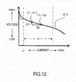
- measurement values of actual output voltage V and output current I are used to calculate the value of ⁇ V/ ⁇ I instead of a mode of storing the value of ⁇ V/ ⁇ I in the steady region P of the characteristic curve Cv1 in steady time of FIG. 7 in Step S205 according to the second and fourth embodiments.
- FIG. 12 shows an I-V characteristic curve of the fuel cell 1 in steady time.
- the gradient ⁇ V/ ⁇ I is calculated by calculating -(V 1 -V 2 )/(I 1 -I 2 ) for output currents I 1 , I 2 measured by the current sensor 51 at predetermined measurement timings and output voltages V 1 , V 2 measured by the voltage sensor 52 at the same predetermined measurement timings.
- the gradient ⁇ V/ ⁇ I regarded as the low frequency impedance is determined according to the measurement values of the output currents and the output voltages.
- the gradient ⁇ V/ ⁇ I in the I-V characteristic curve of the fuel cell 1 is calculated on the basis of two sets (I 1 , V 1 ), (I 2 , V 2 ) of the measurement values of the current and the voltage as just described.
- the value of ⁇ V/ ⁇ I more accurately reflecting an actual characteristic than in the case of using the gradient ⁇ V/ ⁇ I regarded and determined as a constant value in the steady region P can be obtained.
- the accuracy of the estimation value of the reaction resistance value R c of the cathode electrode 113 calculated assuming this value of ⁇ V/ ⁇ I as the low frequency impedance is also improved.
- the gradient ⁇ V/ ⁇ I in the I-V characteristic curve is calculated using one set (I 3 , V 3 ) of measurement values of the output current and the output voltage and one set (I set , V set ) set beforehand instead of measuring two sets (I 1 , V 1 ), (I 2 , V 2 ) of the measurement values of the output current and the output voltage as in the fifth embodiment.
- the value of the gradient ⁇ V/ ⁇ I is calculated by calculating-(V set -V 3 )/(I set -I 3 ) on the basis of the above measurement values (I 3 , V3) and the preset values (I set , V set ).
- the value of the gradient ⁇ V/ ⁇ I in the I-V characteristic curve is calculated on the basis of one set (I 3 , V 3 ) of the measurement values of the current and the voltage and one set (I set , V set ) of the values of the current and the voltage set beforehand.
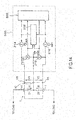
- FIG. 14 is a block diagram schematically showing a main part relating to an impedance measurement in a fuel cell system 100 according to the present embodiment.
- the fuel cell system 100 includes an applied alternating current adjustment unit 200 configured to apply an alternating current to a fuel cell 1 while adjusting the alternating current.
- the applied alternating current adjustment unit 200 is connected to an intermediate terminal 1C besides a positive electrode terminal (cathode electrode side terminal) 1B and a negative electrode terminal (anode electrode side terminal) 1A of a fuel cell 1 configured as a stack. It should be noted that a part connected to the intermediate terminal 1C is grounded as shown.
- the applied alternating current adjustment unit 200 includes a positive electrode side voltage measurement sensor 210 configured to measure a positive electrode side alternating-current potential difference V1 of the positive electrode terminal 1B with respect to the intermediate terminal 1C and a negative electrode side voltage measurement sensor 212 configured to measure a negative electrode side alternating-current potential difference V2 of the negative electrode terminal 1A with respect to the intermediate terminal 1C.
- the applied alternating current adjustment unit 200 includes a positive electrode side alternating-current power supply unit 214 configured to apply an alternating current I1 to a circuit composed of the positive electrode terminal 1B and the intermediate terminal 1C, a negative electrode side alternating-current power supply unit 216 configured to apply an alternating current 12 to a circuit composed of the negative electrode terminal 1A and the intermediate terminal 1C, a controller 218 configured to adjust amplitudes and phases of these alternating currents 11 and 12, and a calculation unit 220 configured to calculate an impedance Z of the fuel cell 1 on the basis of the electrode side alternating-current potential differences V1, V2 and the alternating currents I1, 12.
- the controller 218 adjusts the amplitudes and phases of the alternating currents I1 and I2 such that the positive electrode side alternating-current potential difference V1 and the negative electrode side alternating-current potential difference V2 become equal. It should be noted that this controller 218 may be configured by the controller 6 shown in FIG. 3 .
- the calculation unit 220 includes hardware such as an unillustrated AD converter and a microcomputer chip and software configuration such as a program for calculating the impedance, calculates an impedance Z1 from the intermediate terminal 1C to the positive electrode terminal 1B by dividing the positive electrode side alternating-current potential difference V1 by the alternating current I1 and calculates an impedance Z2 from the intermediate terminal 1C to the negative electrode terminal 1A by dividing the negative electrode side alternating-current potential difference V2 by the alternating current 12. Furthermore, the calculation unit 220 calculates the total impedance Z of the fuel cell 1 by taking the sum of the impedances Z1 and Z2.
- the state detection device for fuel cell includes the alternating-current power supply units 214, 216 connected to the fuel cell 1 and configured to output the alternating currents I1, 12 to the fuel cell 1, the controller 218 serving as an alternating current adjustment unit configured to adjust the alternating currents I1, 12 on the basis of the positive electrode side alternating-current potential difference V1, which is a potential difference obtained by subtracting the potential of the intermediate terminal 1C from the potential of the positive electrode terminal 1B of the fuel cell 1, and the negative electrode side alternating-current potential difference V2, which is a potential difference obtained by subtracting the potential of the intermediate terminal 1C from the potential of the negative electrode terminal 1A of the fuel cell 1, and the impedance calculation unit 220 configured to calculate the impedance Z of the fuel cell 1 on the basis of the adjusted alternating currents I1, I2 and the positive electrodes alternating-current potential difference V1 and the negative electrode side alternating-current potential difference V2.
- the controller 218 adjusts the amplitudes and phases of the alternating current I1 applied by the positive electrode side alternating-current power supply unit 214 and the alternating current 12 applied by the negative electrode side alternating-current power supply unit 216 such that the positive electrode side alternating-current potential difference V1 on the positive electrode side of the fuel cell 1 and the negative electrode side alternating-current potential difference V2 on the negative electrode side substantially match. Since the amplitude of the positive electrode side alternating-current potential difference V1 and that of the negative electrode side alternating-current potential difference V2 become equal in this way, the positive electrode terminal 1B and the negative electrode terminal 1A are substantially at an equal potential. Thus, the alternating currents I1, 12 for the impedance measurement are prevented from flowing to a load 53, wherefore the influence of the fuel cell 1 on power generation is prevented.
- the above embodiments are merely an illustration of some application examples of the present invention and not intended to limit the technical scope of the present invention to the specific configurations of the above embodiments.
- the steps of acquiring the anode electrode response impedance, the electrolyte membrane response impedance and the low frequency impedance (Steps, S101, S103 and S105) and the like in each embodiment can be arbitrarily changed without being limited to the sequence of the steps described in each embodiment.
- each state quantity may be estimated after all the steps of acquiring the anode electrode response impedance, the electrolyte membrane response impedance and the low frequency impedance are performed.
- the modes of estimating a plurality of internal state quantities in the fuel cell 1 are not limited to the modes described in each of the above embodiments.
- two frequencies ⁇ L1 , ⁇ L2 may be selected in the low frequency band and low frequency impedances Z( ⁇ L1 ) and Z( ⁇ L2 ) may be obtained.
- Z( ⁇ L1 ) and Z( ⁇ L2 ) may be obtained.
- the mode of the simplified equivalent circuit of the fuel cell 1 is also not limited to that used in each of the above embodiments.
- an equivalent circuit including other elements such as a diffusion resistance, an electron transport resistance and an ionomer resistance besides the circuit elements such as the reaction resistance and the electrical double layer capacitance of each electrode described in each of the above embodiments may be set, and a diffusion resistance value, an electron transport resistance value, an ionomer resistance value and the like serving as internal state quantities based on these other elements may be estimated.
Landscapes
- Life Sciences & Earth Sciences (AREA)
- Engineering & Computer Science (AREA)
- Manufacturing & Machinery (AREA)
- Sustainable Development (AREA)
- Sustainable Energy (AREA)
- Chemical & Material Sciences (AREA)
- Chemical Kinetics & Catalysis (AREA)
- Electrochemistry (AREA)
- General Chemical & Material Sciences (AREA)
- Fuel Cell (AREA)
Claims (12)
- Brennstoffzellen-Zustandserkennungsvorrichtung, die den internen Zustand einer Brennstoffzelle (1) zur Erzeugung von Energie beim Erhalt einer Zufuhr von Anodengas und Kathodengas, umfassend:eine Impedanz-Erfassungseinheit, die konfiguriert ist, eine erste Frequenzimpedanz und eine zweite Frequenzimpedanz zu erfassen,wobei die erste Frequenzimpedanz auf einer Frequenz basiert, die aus einem ersten Frequenzband ausgewählt ist, und die zweite Frequenzimpedanz auf einer Frequenz basiert, die aus einem zweiten Frequenzband ausgewählt ist, wobei das erste Frequenzband höher als das zweite Frequenzband ist;dadurch gekennzeichnet, dassdas erste Frequenzband ein Frequenzband beinhaltet, das ein Ansprechverhalten zumindest auf eine Zustandsgröße einschließlich eines Reaktionswiderstands einer Anodenelektrode (112) zeigt, und das zweite Frequenzband ein Frequenzband beinhaltet, das ein Ansprechverhalten zumindest auf eine Zustandsgröße einschließlich eines Reaktionswiderstands einer Kathodenelektrode (113) zeigt; und durcheine Internzustandsgrößen-Schätzeinheit, die konfiguriert ist, unter Nutzung einer Gleichung, die auf Grundlage einer Ersatzschaltung der Brennstoffzelle erhalten wurde, jede der Zustandsgröße der Anodenelektrode (112) und der Zustandsgröße der Kathodenelektrode (113) zu schätzen, indem die erfasste erste Frequenzimpedanz und zweite Frequenzimpedanz kombiniert werden, wobei die Zustandsgröße der Anodenelektrode (112) und die Zustandsgröße der Kathodenelektrode (113) als interne Zustände der Brennstoffzelle (1) dienen.
- Brennstoffzellen-Zustandserkennungsvorrichtung nach Anspruch 1, wobei die Internzustandsgrößen-Schätzeinheit:eine bestimmte interne Zustandsgröße auf Grundlage der ersten Frequenzimpedanz schätzt und eine andere interne Zustandsgröße auf Grundlage der geschätzten internen Zustandsgröße und der zweiten Frequenzimpedanz schätzt; odereine bestimmte interne Zustandsgröße auf Grundlage der zweiten Frequenzimpedanz schätzt und eine andere interne Zustandsgröße auf Grundlage der geschätzten internen Zustandsgröße und der ersten Frequenzimpedanz schätzt.
- Brennstoffzellen-Zustandserkennungsvorrichtung nach Anspruch 1 oder 2, wobei
das erste Frequenzband ein Anodenelektroden-Ansprechfrequenzband und ein Elektrolytmembran-Ansprechfrequenzband beinhaltet, wobei das Anodenelektroden-Ansprechfrequenzband ein Frequenzband ist, das ein Ansprechverhalten auf eine Zustandsgröße der Anodenelektrode (112) der Brennstoffzelle (1) zeigt, und das Elektrolytmembran-Ansprechfrequenzband ein Frequenzband ist, das höher als das Anodenelektroden-Ansprechfrequenzband ist und ein Ansprechverhalten auf eine Zustandsgröße einer Elektrolytmembran der Brennstoffzelle (1) zeigt; und
die Impedanz-Erfassungseinheit zumindest eine von einer Anodenelektroden-Ansprechimpedanz auf Grundlage einer Frequenz, die aus dem Anodenelektroden-Ansprechfrequenzband gewählt ist, und einer Elektrolytmembran-Ansprechimpedanz auf Grundlage einer Frequenz, die aus dem Elektrolytmembran-Ansprechfrequenzband gewählt ist, als die erste Frequenzimpedanz erfasst. - Brennstoffzellen-Zustandserkennungsvorrichtung nach Anspruch 3, wobei:die Impedanz-Erfassungseinheit sowohl die Anodenelektroden-Ansprechimpedanz als auch die Elektrolytmembran-Ansprechimpedanz als die erste Frequenzimpedanz erfasst; unddie Internzustandsgrößen-Schätzeinheit die Zustandsgröße der Elektrolytmembran auf Grundlage der Elektrolytmembran-Ansprechimpedanz schätzt und die Zustandsgröße der Anodenelektrode (112) auf Grundlage der geschätzten Zustandsgröße der Elektrolytmembran und der Anodenelektroden-Ansprechimpedanz schätzt.
- Brennstoffzellen-Zustandserkennungsvorrichtung nach Anspruch 3, wobei:die Impedanz-Erfassungseinheit nur die Anodenelektroden-Ansprechimpedanz als die erste Frequenzimpedanz erfasst; unddie Internzustandsgrößen-Schätzeinheit die Zustandsgröße der Anodenelektrode (112) auf Grundlage der Anodenelektroden-Ansprechimpedanz schätzt.
- Brennstoffzellen-Zustandserkennungsvorrichtung nach Anspruch 4, wobei:die Zustandsgröße der Anodenelektrode (112) einen Reaktionswiderstandswert und einen elektrischen Doppelschicht-Kapazitätswert der Anodenelektrode (112) beinhaltet;die Zustandsgröße der Kathodenelektrode (113) einen Reaktionswiderstandswert und einen elektrischen Doppelschicht-Kapazitätswert der Kathodenelektrode (113) beinhaltet; unddie Internzustandsgrößen-Schätzeinheit:den Reaktionswiderstandswert der Anodenelektrode (112) und den elektrischen Doppelschicht-Kapazitätswert der Anodenelektrode (112) auf Grundlage der Anodenelektroden-Ansprechimpedanz schätz; undzumindest einen des Reaktionswiderstandwerts und des elektrischen Doppelschicht-Kapazitätswert der Kathodenelektrode (113) schätzt, auf Grundlage der geschätzten Zustandsgröße der Elektrolytmembran, des Reaktionswiderstands der Anodenelektrode (112), der elektrischen Doppelschicht-Kapazität der Anodenelektrode (112) und der zweiten Frequenzimpedanz.
- Brennstoffzellen-Zustandserkennungsvorrichtung nach einem der Ansprüche 1 bis 6, wobei
die Impedanz-Erfassungseinheit einen Wert eines Gradienten in einer I-V Kennlinie der Brennstoffzelle (1) als die zweite Frequenzimpedanz erfasst. - Brennstoffzellen-Zustandserkennungsvorrichtung nach Anspruch 7, wobei
die Impedanz-Erfassungseinheit den Wert des Gradienten als die zweite Frequenzimpedanz in einer stabilen Zeit erfasst, in der eine Änderung des Werts des Gradienten in der I-V Kennlinie der Brennstoffzelle (1) nicht größer als ein vorbestimmter Wert ist. - Brennstoffzellen-Zustandserkennungsvorrichtung nach Anspruch 7 oder 8, wobei
der Gradient in der I-V Kennlinie auf Grundlage von zwei Sätzen von Messwerten einer Stromstärke und einer Spannung berechnet wird. - Brennstoffzellen-Zustandserkennungsvorrichtung nach Anspruch 7 oder 8, wobei:
der Gradient in der I-V Kennlinie auf Grundlage eines Satzes von Messwerten einer Stromstärke und einer Spannung und einem Satz von Stromstärke und Spannung, die im Voraus festgelegt wurden, berechnet wird. - Brennstoffzellen-Zustandserkennungsvorrichtung nach einem der Ansprüche 1 bis 10, wobei:die Brennstoffzelle (1) als laminierte Batterie konfiguriert ist; unddie Zustandserkennungsvorrichtung umfasst:eine Wechselstrom-Energieversorgungseinheit, die mit der laminierten Batterie verbunden ist und konfiguriert ist, einen Wechselstrom an die laminierte Batterie auszugeben;eine Wechselstrom-Anpassungseinheit, die konfiguriert ist, den Wechselstrom anzupassen, auf Grundlage einer Wechselstrom-Potentialdifferent einer positiven Elektrodenseite und einer Wechselstrom-Potentialdifferenz einer negativen Elektrodenseite, wobei die Wechselstrom-Potentialdifferent der positiven Elektrodenseite eine Potentialdifferenz ist, die durch Subtraktion eines Potentials eines Zwischenabschnitts der laminierten Batterie von einem Potential an einer positiven Elektrodenseite der laminierten Batterie erhalten wird, und die Wechselstrom-Potentialdifferenz der negativen Elektrodenseite eine Potentialdifferent ist, die durch Subtraktion des Potentials des Zwischenabschnitts der laminierten Batterie von einem Potential an einer negativen Elektrodenseite der laminierten Batterie erhalten wird; undeine Impedanz-Berechnungseinheit, die konfiguriert ist, einen Impedanzmesswert der Brennstoffzelle (1) zu berechnen, auf Grundlage des angepassten Wechselstroms und der Wechselstrom-Potentialdifferent der positiven Elektrodenseite und der Wechselstrom-Potentialdifferenz der negativen Elektrodenseite.
- Brennstoffzellen-Zustandserkennungsverfahren, das den internen Zustand einer Brennstoffzelle (1) zur Erzeugung von Energie beim Erhalt einer Zufuhr von Anodengas und Kathodengas bestimmt, umfassend:einen Schritt zur Erfassung einer ersten Frequenzimpedanz und einer zweiten Frequenzimpedanz,wobei die erste Frequenzimpedanz auf einer Frequenz basiert, die aus einem ersten Frequenzband ausgewählt ist, und die zweite Frequenzimpedanz auf einer Frequenz basiert, die aus einem zweiten Frequenzband ausgewählt ist, wobei das erste Frequenzband höher als das zweite Frequenzband ist;dadurch gekennzeichnet, dassdas erste Frequenzband ein Frequenzband beinhaltet, das ein Ansprechverhalten zumindest auf eine Zustandsgröße einschließlich eines Reaktionswiderstands einer Anodenelektrode zeigt, und das zweite Frequenzband ein Frequenzband beinhaltet, das ein Ansprechverhalten zumindest auf eine Zustandsgröße einschließlich eines Reaktionswiderstands einer Kathodenelektrode (113) zeigt; und durcheinen Schritt zum Schätzen von jeder der Zustandsgröße der Anodenelektrode (112) und der Zustandsgröße der Kathodenelektrode (113), die als interne Zustände der Brennstoffzelle dienen, unter Nutzung einer Gleichung, die auf Grundlage einer Ersatzschaltung der Brennstoffzelle erhalten wurde, indem die erfasste erste Frequenzimpedanz und zweite Frequenzimpedanz kombiniert werden.
Applications Claiming Priority (1)
| Application Number | Priority Date | Filing Date | Title |
|---|---|---|---|
| PCT/JP2014/084566 WO2016103462A1 (ja) | 2014-12-26 | 2014-12-26 | 燃料電池の状態検出装置及び方法 |
Publications (3)
| Publication Number | Publication Date |
|---|---|
| EP3240073A1 EP3240073A1 (de) | 2017-11-01 |
| EP3240073A4 EP3240073A4 (de) | 2018-02-21 |
| EP3240073B1 true EP3240073B1 (de) | 2019-09-11 |
Family
ID=56149550
Family Applications (1)
| Application Number | Title | Priority Date | Filing Date |
|---|---|---|---|
| EP14909066.4A Not-in-force EP3240073B1 (de) | 2014-12-26 | 2014-12-26 | Vorrichtung und verfahren zur bestimmung des zustands einer brennstoffbatterie |
Country Status (6)
| Country | Link |
|---|---|
| US (1) | US20170373331A1 (de) |
| EP (1) | EP3240073B1 (de) |
| JP (1) | JP6350678B2 (de) |
| CN (1) | CN107112558B (de) |
| CA (1) | CA2972354C (de) |
| WO (1) | WO2016103462A1 (de) |
Families Citing this family (5)
| Publication number | Priority date | Publication date | Assignee | Title |
|---|---|---|---|---|
| CN108140856B (zh) | 2015-10-05 | 2020-09-29 | 日产自动车株式会社 | 燃料电池的状态判定方法和状态判定装置 |
| JP6897626B2 (ja) * | 2018-04-12 | 2021-06-30 | トヨタ自動車株式会社 | 燃料電池システム及び金属イオン含有量の推定方法 |
| JP7596835B2 (ja) * | 2021-02-12 | 2024-12-10 | 株式会社アイシン | 燃料電池システム |
| CN114236407B (zh) * | 2021-12-16 | 2023-02-28 | 海南大学 | 能量转换装置的性能损失测定方法及装置 |
| CN114976145B (zh) * | 2022-05-31 | 2023-09-26 | 重庆明天氢能科技有限公司 | 一种防止燃料电池系统监测部件漏装的控制方法 |
Citations (1)
| Publication number | Priority date | Publication date | Assignee | Title |
|---|---|---|---|---|
| US20140295302A1 (en) * | 2013-04-02 | 2014-10-02 | Denso Corporation | Fuel cell monitoring device |
Family Cites Families (9)
| Publication number | Priority date | Publication date | Assignee | Title |
|---|---|---|---|---|
| JP4595367B2 (ja) * | 2004-03-30 | 2010-12-08 | トヨタ自動車株式会社 | 燃料電池の劣化診断方法及び装置 |
| JP4821962B2 (ja) * | 2005-06-30 | 2011-11-24 | トヨタ自動車株式会社 | 燃料電池システム |
| JP2007066589A (ja) * | 2005-08-30 | 2007-03-15 | Yokogawa Electric Corp | 燃料電池の特性評価方法および特性評価装置 |
| JP2009134924A (ja) * | 2007-11-29 | 2009-06-18 | Yokogawa Electric Corp | 燃料電池の特性評価方法および特性評価装置 |
| JP4640661B2 (ja) * | 2009-01-13 | 2011-03-02 | トヨタ自動車株式会社 | 燃料電池システム |
| JP5793989B2 (ja) * | 2011-06-24 | 2015-10-14 | 株式会社日本自動車部品総合研究所 | 燃料電池状態診断装置 |
| JP5724911B2 (ja) * | 2012-03-13 | 2015-05-27 | 株式会社日本自動車部品総合研究所 | 燃料電池診断装置 |
| JP5811958B2 (ja) * | 2012-06-12 | 2015-11-11 | 株式会社日本自動車部品総合研究所 | 乾湿指標測定装置、および燃料電池診断装置 |
| JP6024315B2 (ja) * | 2012-09-07 | 2016-11-16 | 株式会社日本自動車部品総合研究所 | 燃料電池診断装置 |
-
2014
- 2014-12-26 EP EP14909066.4A patent/EP3240073B1/de not_active Not-in-force
- 2014-12-26 CA CA2972354A patent/CA2972354C/en active Active
- 2014-12-26 US US15/539,334 patent/US20170373331A1/en not_active Abandoned
- 2014-12-26 CN CN201480084391.8A patent/CN107112558B/zh not_active Expired - Fee Related
- 2014-12-26 JP JP2016565811A patent/JP6350678B2/ja not_active Expired - Fee Related
- 2014-12-26 WO PCT/JP2014/084566 patent/WO2016103462A1/ja not_active Ceased
Patent Citations (1)
| Publication number | Priority date | Publication date | Assignee | Title |
|---|---|---|---|---|
| US20140295302A1 (en) * | 2013-04-02 | 2014-10-02 | Denso Corporation | Fuel cell monitoring device |
Also Published As
| Publication number | Publication date |
|---|---|
| CA2972354C (en) | 2019-09-17 |
| EP3240073A4 (de) | 2018-02-21 |
| EP3240073A1 (de) | 2017-11-01 |
| CN107112558A (zh) | 2017-08-29 |
| US20170373331A1 (en) | 2017-12-28 |
| CN107112558B (zh) | 2018-06-19 |
| CA2972354A1 (en) | 2016-06-30 |
| WO2016103462A1 (ja) | 2016-06-30 |
| JPWO2016103462A1 (ja) | 2017-11-24 |
| JP6350678B2 (ja) | 2018-07-04 |
Similar Documents
| Publication | Publication Date | Title |
|---|---|---|
| US10193174B2 (en) | Fuel cell internal state detection system and state detection method | |
| EP3217458B1 (de) | Ein brennstoffzellensystem und ein verfahren zur bestimmung des zustands der brennstoffzellen | |
| EP1898483B1 (de) | Brennstoffzellsystem | |
| US10115987B2 (en) | State detection device and method for fuel cell | |
| US10038207B2 (en) | Fuel cell system | |
| EP3240073B1 (de) | Vorrichtung und verfahren zur bestimmung des zustands einer brennstoffbatterie | |
| JP2017084451A (ja) | 燃料電池の触媒劣化判定方法及び触媒劣化判定装置 | |
| US11054473B2 (en) | State estimation device and method for fuel cell and fuel cell system | |
| EP2306572B1 (de) | Brennstoffzellensystem | |
| EP3361540B1 (de) | Brennstoffzellenzustandsbestimmungsverfahren und zustandsbestimmungsvorrichtung | |
| JP6507507B2 (ja) | 燃料電池の内部状態推定装置 |
Legal Events
| Date | Code | Title | Description |
|---|---|---|---|
| STAA | Information on the status of an ep patent application or granted ep patent |
Free format text: STATUS: THE INTERNATIONAL PUBLICATION HAS BEEN MADE |
|
| PUAI | Public reference made under article 153(3) epc to a published international application that has entered the european phase |
Free format text: ORIGINAL CODE: 0009012 |
|
| STAA | Information on the status of an ep patent application or granted ep patent |
Free format text: STATUS: REQUEST FOR EXAMINATION WAS MADE |
|
| 17P | Request for examination filed |
Effective date: 20170726 |
|
| AK | Designated contracting states |
Kind code of ref document: A1 Designated state(s): AL AT BE BG CH CY CZ DE DK EE ES FI FR GB GR HR HU IE IS IT LI LT LU LV MC MK MT NL NO PL PT RO RS SE SI SK SM TR |
|
| AX | Request for extension of the european patent |
Extension state: BA ME |
|
| REG | Reference to a national code |
Ref country code: DE Ref legal event code: R079 Ref document number: 602014053700 Country of ref document: DE Free format text: PREVIOUS MAIN CLASS: H01M0008040000 Ipc: H01M0008043800 |
|
| A4 | Supplementary search report drawn up and despatched |
Effective date: 20180119 |
|
| RIC1 | Information provided on ipc code assigned before grant |
Ipc: H01M 8/0438 20160101AFI20180115BHEP Ipc: H01M 8/04537 20160101ALI20180115BHEP |
|
| DAX | Request for extension of the european patent (deleted) | ||
| STAA | Information on the status of an ep patent application or granted ep patent |
Free format text: STATUS: EXAMINATION IS IN PROGRESS |
|
| 17Q | First examination report despatched |
Effective date: 20180919 |
|
| GRAP | Despatch of communication of intention to grant a patent |
Free format text: ORIGINAL CODE: EPIDOSNIGR1 |
|
| STAA | Information on the status of an ep patent application or granted ep patent |
Free format text: STATUS: GRANT OF PATENT IS INTENDED |
|
| INTG | Intention to grant announced |
Effective date: 20190516 |
|
| RIN1 | Information on inventor provided before grant (corrected) |
Inventor name: AOKI, TETSUYA |
|
| GRAS | Grant fee paid |
Free format text: ORIGINAL CODE: EPIDOSNIGR3 |
|
| GRAA | (expected) grant |
Free format text: ORIGINAL CODE: 0009210 |
|
| STAA | Information on the status of an ep patent application or granted ep patent |
Free format text: STATUS: THE PATENT HAS BEEN GRANTED |
|
| AK | Designated contracting states |
Kind code of ref document: B1 Designated state(s): AL AT BE BG CH CY CZ DE DK EE ES FI FR GB GR HR HU IE IS IT LI LT LU LV MC MK MT NL NO PL PT RO RS SE SI SK SM TR |
|
| REG | Reference to a national code |
Ref country code: GB Ref legal event code: FG4D |
|
| REG | Reference to a national code |
Ref country code: CH Ref legal event code: EP |
|
| REG | Reference to a national code |
Ref country code: AT Ref legal event code: REF Ref document number: 1179669 Country of ref document: AT Kind code of ref document: T Effective date: 20190915 |
|
| REG | Reference to a national code |
Ref country code: DE Ref legal event code: R096 Ref document number: 602014053700 Country of ref document: DE |
|
| REG | Reference to a national code |
Ref country code: IE Ref legal event code: FG4D |
|
| REG | Reference to a national code |
Ref country code: NL Ref legal event code: MP Effective date: 20190911 |
|
| REG | Reference to a national code |
Ref country code: LT Ref legal event code: MG4D |
|
| PG25 | Lapsed in a contracting state [announced via postgrant information from national office to epo] |
Ref country code: HR Free format text: LAPSE BECAUSE OF FAILURE TO SUBMIT A TRANSLATION OF THE DESCRIPTION OR TO PAY THE FEE WITHIN THE PRESCRIBED TIME-LIMIT Effective date: 20190911 Ref country code: SE Free format text: LAPSE BECAUSE OF FAILURE TO SUBMIT A TRANSLATION OF THE DESCRIPTION OR TO PAY THE FEE WITHIN THE PRESCRIBED TIME-LIMIT Effective date: 20190911 Ref country code: BG Free format text: LAPSE BECAUSE OF FAILURE TO SUBMIT A TRANSLATION OF THE DESCRIPTION OR TO PAY THE FEE WITHIN THE PRESCRIBED TIME-LIMIT Effective date: 20191211 Ref country code: LT Free format text: LAPSE BECAUSE OF FAILURE TO SUBMIT A TRANSLATION OF THE DESCRIPTION OR TO PAY THE FEE WITHIN THE PRESCRIBED TIME-LIMIT Effective date: 20190911 Ref country code: FI Free format text: LAPSE BECAUSE OF FAILURE TO SUBMIT A TRANSLATION OF THE DESCRIPTION OR TO PAY THE FEE WITHIN THE PRESCRIBED TIME-LIMIT Effective date: 20190911 Ref country code: NO Free format text: LAPSE BECAUSE OF FAILURE TO SUBMIT A TRANSLATION OF THE DESCRIPTION OR TO PAY THE FEE WITHIN THE PRESCRIBED TIME-LIMIT Effective date: 20191211 |
|
| PG25 | Lapsed in a contracting state [announced via postgrant information from national office to epo] |
Ref country code: LV Free format text: LAPSE BECAUSE OF FAILURE TO SUBMIT A TRANSLATION OF THE DESCRIPTION OR TO PAY THE FEE WITHIN THE PRESCRIBED TIME-LIMIT Effective date: 20190911 Ref country code: ES Free format text: LAPSE BECAUSE OF FAILURE TO SUBMIT A TRANSLATION OF THE DESCRIPTION OR TO PAY THE FEE WITHIN THE PRESCRIBED TIME-LIMIT Effective date: 20190911 Ref country code: AL Free format text: LAPSE BECAUSE OF FAILURE TO SUBMIT A TRANSLATION OF THE DESCRIPTION OR TO PAY THE FEE WITHIN THE PRESCRIBED TIME-LIMIT Effective date: 20190911 Ref country code: GR Free format text: LAPSE BECAUSE OF FAILURE TO SUBMIT A TRANSLATION OF THE DESCRIPTION OR TO PAY THE FEE WITHIN THE PRESCRIBED TIME-LIMIT Effective date: 20191212 Ref country code: RS Free format text: LAPSE BECAUSE OF FAILURE TO SUBMIT A TRANSLATION OF THE DESCRIPTION OR TO PAY THE FEE WITHIN THE PRESCRIBED TIME-LIMIT Effective date: 20190911 |
|
| REG | Reference to a national code |
Ref country code: AT Ref legal event code: MK05 Ref document number: 1179669 Country of ref document: AT Kind code of ref document: T Effective date: 20190911 |
|
| PG25 | Lapsed in a contracting state [announced via postgrant information from national office to epo] |
Ref country code: AT Free format text: LAPSE BECAUSE OF FAILURE TO SUBMIT A TRANSLATION OF THE DESCRIPTION OR TO PAY THE FEE WITHIN THE PRESCRIBED TIME-LIMIT Effective date: 20190911 Ref country code: PL Free format text: LAPSE BECAUSE OF FAILURE TO SUBMIT A TRANSLATION OF THE DESCRIPTION OR TO PAY THE FEE WITHIN THE PRESCRIBED TIME-LIMIT Effective date: 20190911 Ref country code: PT Free format text: LAPSE BECAUSE OF FAILURE TO SUBMIT A TRANSLATION OF THE DESCRIPTION OR TO PAY THE FEE WITHIN THE PRESCRIBED TIME-LIMIT Effective date: 20200113 Ref country code: EE Free format text: LAPSE BECAUSE OF FAILURE TO SUBMIT A TRANSLATION OF THE DESCRIPTION OR TO PAY THE FEE WITHIN THE PRESCRIBED TIME-LIMIT Effective date: 20190911 Ref country code: RO Free format text: LAPSE BECAUSE OF FAILURE TO SUBMIT A TRANSLATION OF THE DESCRIPTION OR TO PAY THE FEE WITHIN THE PRESCRIBED TIME-LIMIT Effective date: 20190911 Ref country code: NL Free format text: LAPSE BECAUSE OF FAILURE TO SUBMIT A TRANSLATION OF THE DESCRIPTION OR TO PAY THE FEE WITHIN THE PRESCRIBED TIME-LIMIT Effective date: 20190911 Ref country code: IT Free format text: LAPSE BECAUSE OF FAILURE TO SUBMIT A TRANSLATION OF THE DESCRIPTION OR TO PAY THE FEE WITHIN THE PRESCRIBED TIME-LIMIT Effective date: 20190911 |
|
| PG25 | Lapsed in a contracting state [announced via postgrant information from national office to epo] |
Ref country code: SM Free format text: LAPSE BECAUSE OF FAILURE TO SUBMIT A TRANSLATION OF THE DESCRIPTION OR TO PAY THE FEE WITHIN THE PRESCRIBED TIME-LIMIT Effective date: 20190911 Ref country code: CZ Free format text: LAPSE BECAUSE OF FAILURE TO SUBMIT A TRANSLATION OF THE DESCRIPTION OR TO PAY THE FEE WITHIN THE PRESCRIBED TIME-LIMIT Effective date: 20190911 Ref country code: IS Free format text: LAPSE BECAUSE OF FAILURE TO SUBMIT A TRANSLATION OF THE DESCRIPTION OR TO PAY THE FEE WITHIN THE PRESCRIBED TIME-LIMIT Effective date: 20200224 Ref country code: SK Free format text: LAPSE BECAUSE OF FAILURE TO SUBMIT A TRANSLATION OF THE DESCRIPTION OR TO PAY THE FEE WITHIN THE PRESCRIBED TIME-LIMIT Effective date: 20190911 |
|
| REG | Reference to a national code |
Ref country code: DE Ref legal event code: R097 Ref document number: 602014053700 Country of ref document: DE |
|
| PLBE | No opposition filed within time limit |
Free format text: ORIGINAL CODE: 0009261 |
|
| STAA | Information on the status of an ep patent application or granted ep patent |
Free format text: STATUS: NO OPPOSITION FILED WITHIN TIME LIMIT |
|
| PG2D | Information on lapse in contracting state deleted |
Ref country code: IS |
|
| PG25 | Lapsed in a contracting state [announced via postgrant information from national office to epo] |
Ref country code: DK Free format text: LAPSE BECAUSE OF FAILURE TO SUBMIT A TRANSLATION OF THE DESCRIPTION OR TO PAY THE FEE WITHIN THE PRESCRIBED TIME-LIMIT Effective date: 20190911 Ref country code: IS Free format text: LAPSE BECAUSE OF FAILURE TO SUBMIT A TRANSLATION OF THE DESCRIPTION OR TO PAY THE FEE WITHIN THE PRESCRIBED TIME-LIMIT Effective date: 20200112 |
|
| REG | Reference to a national code |
Ref country code: CH Ref legal event code: PL |
|
| 26N | No opposition filed |
Effective date: 20200615 |
|
| REG | Reference to a national code |
Ref country code: BE Ref legal event code: MM Effective date: 20191231 |
|
| PG25 | Lapsed in a contracting state [announced via postgrant information from national office to epo] |
Ref country code: SI Free format text: LAPSE BECAUSE OF FAILURE TO SUBMIT A TRANSLATION OF THE DESCRIPTION OR TO PAY THE FEE WITHIN THE PRESCRIBED TIME-LIMIT Effective date: 20190911 Ref country code: MC Free format text: LAPSE BECAUSE OF FAILURE TO SUBMIT A TRANSLATION OF THE DESCRIPTION OR TO PAY THE FEE WITHIN THE PRESCRIBED TIME-LIMIT Effective date: 20190911 |
|
| PG25 | Lapsed in a contracting state [announced via postgrant information from national office to epo] |
Ref country code: IE Free format text: LAPSE BECAUSE OF NON-PAYMENT OF DUE FEES Effective date: 20191226 Ref country code: LU Free format text: LAPSE BECAUSE OF NON-PAYMENT OF DUE FEES Effective date: 20191226 |
|
| PG25 | Lapsed in a contracting state [announced via postgrant information from national office to epo] |
Ref country code: LI Free format text: LAPSE BECAUSE OF NON-PAYMENT OF DUE FEES Effective date: 20191231 Ref country code: CH Free format text: LAPSE BECAUSE OF NON-PAYMENT OF DUE FEES Effective date: 20191231 Ref country code: BE Free format text: LAPSE BECAUSE OF NON-PAYMENT OF DUE FEES Effective date: 20191231 |
|
| PG25 | Lapsed in a contracting state [announced via postgrant information from national office to epo] |
Ref country code: CY Free format text: LAPSE BECAUSE OF FAILURE TO SUBMIT A TRANSLATION OF THE DESCRIPTION OR TO PAY THE FEE WITHIN THE PRESCRIBED TIME-LIMIT Effective date: 20190911 |
|
| PG25 | Lapsed in a contracting state [announced via postgrant information from national office to epo] |
Ref country code: MT Free format text: LAPSE BECAUSE OF FAILURE TO SUBMIT A TRANSLATION OF THE DESCRIPTION OR TO PAY THE FEE WITHIN THE PRESCRIBED TIME-LIMIT Effective date: 20190911 Ref country code: HU Free format text: LAPSE BECAUSE OF FAILURE TO SUBMIT A TRANSLATION OF THE DESCRIPTION OR TO PAY THE FEE WITHIN THE PRESCRIBED TIME-LIMIT; INVALID AB INITIO Effective date: 20141226 |
|
| PGFP | Annual fee paid to national office [announced via postgrant information from national office to epo] |
Ref country code: GB Payment date: 20211104 Year of fee payment: 8 Ref country code: DE Payment date: 20211102 Year of fee payment: 8 Ref country code: FR Payment date: 20211116 Year of fee payment: 8 |
|
| PG25 | Lapsed in a contracting state [announced via postgrant information from national office to epo] |
Ref country code: TR Free format text: LAPSE BECAUSE OF FAILURE TO SUBMIT A TRANSLATION OF THE DESCRIPTION OR TO PAY THE FEE WITHIN THE PRESCRIBED TIME-LIMIT Effective date: 20190911 |
|
| PG25 | Lapsed in a contracting state [announced via postgrant information from national office to epo] |
Ref country code: MK Free format text: LAPSE BECAUSE OF FAILURE TO SUBMIT A TRANSLATION OF THE DESCRIPTION OR TO PAY THE FEE WITHIN THE PRESCRIBED TIME-LIMIT Effective date: 20190911 |
|
| REG | Reference to a national code |
Ref country code: DE Ref legal event code: R119 Ref document number: 602014053700 Country of ref document: DE |
|
| GBPC | Gb: european patent ceased through non-payment of renewal fee |
Effective date: 20221226 |
|
| PG25 | Lapsed in a contracting state [announced via postgrant information from national office to epo] |
Ref country code: GB Free format text: LAPSE BECAUSE OF NON-PAYMENT OF DUE FEES Effective date: 20221226 Ref country code: DE Free format text: LAPSE BECAUSE OF NON-PAYMENT OF DUE FEES Effective date: 20230701 |
|
| PG25 | Lapsed in a contracting state [announced via postgrant information from national office to epo] |
Ref country code: FR Free format text: LAPSE BECAUSE OF NON-PAYMENT OF DUE FEES Effective date: 20221231 |