EP3240080A1 - Fuel cell device - Google Patents
Fuel cell device Download PDFInfo
- Publication number
- EP3240080A1 EP3240080A1 EP16167054.2A EP16167054A EP3240080A1 EP 3240080 A1 EP3240080 A1 EP 3240080A1 EP 16167054 A EP16167054 A EP 16167054A EP 3240080 A1 EP3240080 A1 EP 3240080A1
- Authority
- EP
- European Patent Office
- Prior art keywords
- unit
- fuel cell
- desulfurization
- fuel
- reformer
- Prior art date
- Legal status (The legal status is an assumption and is not a legal conclusion. Google has not performed a legal analysis and makes no representation as to the accuracy of the status listed.)
- Granted
Links
Images

Classifications
-
- H—ELECTRICITY
- H01—ELECTRIC ELEMENTS
- H01M—PROCESSES OR MEANS, e.g. BATTERIES, FOR THE DIRECT CONVERSION OF CHEMICAL ENERGY INTO ELECTRICAL ENERGY
- H01M8/00—Fuel cells; Manufacture thereof
- H01M8/06—Combination of fuel cells with means for production of reactants or for treatment of residues
- H01M8/0662—Treatment of gaseous reactants or gaseous residues, e.g. cleaning
- H01M8/0675—Removal of sulfur
-
- H—ELECTRICITY
- H01—ELECTRIC ELEMENTS
- H01M—PROCESSES OR MEANS, e.g. BATTERIES, FOR THE DIRECT CONVERSION OF CHEMICAL ENERGY INTO ELECTRICAL ENERGY
- H01M8/00—Fuel cells; Manufacture thereof
- H01M8/04—Auxiliary arrangements, e.g. for control of pressure or for circulation of fluids
- H01M8/04082—Arrangements for control of reactant parameters, e.g. pressure or concentration
-
- H—ELECTRICITY
- H01—ELECTRIC ELEMENTS
- H01M—PROCESSES OR MEANS, e.g. BATTERIES, FOR THE DIRECT CONVERSION OF CHEMICAL ENERGY INTO ELECTRICAL ENERGY
- H01M8/00—Fuel cells; Manufacture thereof
- H01M8/04—Auxiliary arrangements, e.g. for control of pressure or for circulation of fluids
- H01M8/04223—Auxiliary arrangements, e.g. for control of pressure or for circulation of fluids during start-up or shut-down; Depolarisation or activation, e.g. purging; Means for short-circuiting defective fuel cells
- H01M8/04228—Auxiliary arrangements, e.g. for control of pressure or for circulation of fluids during start-up or shut-down; Depolarisation or activation, e.g. purging; Means for short-circuiting defective fuel cells during shut-down
-
- H—ELECTRICITY
- H01—ELECTRIC ELEMENTS
- H01M—PROCESSES OR MEANS, e.g. BATTERIES, FOR THE DIRECT CONVERSION OF CHEMICAL ENERGY INTO ELECTRICAL ENERGY
- H01M8/00—Fuel cells; Manufacture thereof
- H01M8/06—Combination of fuel cells with means for production of reactants or for treatment of residues
- H01M8/0606—Combination of fuel cells with means for production of reactants or for treatment of residues with means for production of gaseous reactants
- H01M8/0612—Combination of fuel cells with means for production of reactants or for treatment of residues with means for production of gaseous reactants from carbon-containing material
- H01M8/0618—Reforming processes, e.g. autothermal, partial oxidation or steam reforming
-
- H—ELECTRICITY
- H01—ELECTRIC ELEMENTS
- H01M—PROCESSES OR MEANS, e.g. BATTERIES, FOR THE DIRECT CONVERSION OF CHEMICAL ENERGY INTO ELECTRICAL ENERGY
- H01M8/00—Fuel cells; Manufacture thereof
- H01M8/10—Fuel cells with solid electrolytes
- H01M8/12—Fuel cells with solid electrolytes operating at high temperature, e.g. with stabilised ZrO2 electrolyte
- H01M2008/1293—Fuel cells with solid oxide electrolytes
-
- Y—GENERAL TAGGING OF NEW TECHNOLOGICAL DEVELOPMENTS; GENERAL TAGGING OF CROSS-SECTIONAL TECHNOLOGIES SPANNING OVER SEVERAL SECTIONS OF THE IPC; TECHNICAL SUBJECTS COVERED BY FORMER USPC CROSS-REFERENCE ART COLLECTIONS [XRACs] AND DIGESTS
- Y02—TECHNOLOGIES OR APPLICATIONS FOR MITIGATION OR ADAPTATION AGAINST CLIMATE CHANGE
- Y02E—REDUCTION OF GREENHOUSE GAS [GHG] EMISSIONS, RELATED TO ENERGY GENERATION, TRANSMISSION OR DISTRIBUTION
- Y02E60/00—Enabling technologies; Technologies with a potential or indirect contribution to GHG emissions mitigation
- Y02E60/30—Hydrogen technology
- Y02E60/50—Fuel cells
Definitions
- Fuel cell device which is provided to be operated with a fluidic fuel, with a desulfurization unit, which is provided to desulfurize the fuel at least partially, with a reformer unit, which is provided for generating at least one fuel gas, and with a fuel cell unit, is already known.
- the invention is based on a fuel cell device, which is provided to be operated with a fluidic fuel, with a desulfurization unit, which is provided to desulfurize the fuel at least partially, with a reformer unit, which is provided for generating at least one fuel gas, and with a fuel cell unit.
- the desulfurization unit is provided for at least limiting a transfer of at least one noxious gas from the desulfurization unit into the reformer unit and/or into the fuel cell unit at least when shutting down the fuel cell unit.
- a “fuel cell device” is to be understood in particular a functional component, in particular a structural and/or functioning component of a fuel cell system.
- a “fuel cell system” is to be understood as a system provided for stationary and/or mobile generation of in particular electrical and/or thermal energy by using at least one fuel cell unit.
- “Provided” is to be understood in particular as specifically programmed, designed and/or equipped.
- a fuel cell unit a unit with at least one fuel cell, which is provided for converting at least a chemical reaction energy of at least one in particular continuously supplied fuel gas, in particular hydrogen and/or carbon monoxide, and at least one oxidizing agent, in particular oxygen from air, into electrical and/or thermal energy.
- the at least one fuel cell may be embodied in particular as a solid oxide fuel cell (SOFC).
- SOFC solid oxide fuel cell
- the fuel cell unit comprises a plurality of fuel cells, which are in particular arranged in a fuel cell stack.
- a "desulfurization unit” is to be understood as a unit provided to reduce a volume and/or mole fraction of sulfur compounds in the fuel, in particular below a specified threshold value and preferably to remove a volume and/or mole fraction of sulfur compounds in the fuel at least substantially from the fuel, preferably by at least one physical and/or chemical adsorption and/or absorption process.
- a "reformer unit” in particular a chemical-technical unit is to be understood, which is provided for processing the fuel in particular for generating a fuel gas containing gas mixture, in particular by partial oxidation and/or by an autothermal reforming and/or preferably by steam reforming.
- the reformer unit is embodied as a steam reformer unit.
- a “steam reformer unit” is to be understood in particular as a reformer unit provided to process the fuel by addition of water vapor for generating the fuel gas containing gas mixture.
- the fuel cell device comprises a water supply unit which is provided for supplying water to the reformer unit during a normal operation of the fuel cell unit.
- a “water supply unit” is to be understood in particular a unit, which is provided for supplying water which is required for a reforming process to the reformer unit.
- the water supply unit is provided for supplying water continuously to the reformer unit.
- the water supply unit comprises at least one water supply pump provided for in particular continuous conveyance of the water.
- the water supply unit in particular comprises at least one vaporizer, which is fluidically arranged upstream of the reformer unit and which is provided for vaporizing the supplied water.
- a "noxious gas” is to be understood in particular a gaseous substance, which is able to damage and/or destroy at least one unit and/or component of the fuel cell device if the gaseous substance is led into said unit and/or component.
- the noxious gas is methane or a methane containing gas mixture.
- materials of the desulfurization unit may absorb methane.
- the absorbed methane may be desorbed, which may lead to a coking of the reformer unit and/or the fuel cell unit if the methane streams into the reformer unit/or the fuel cell unit. In particular, this may occur if no water or an insufficient amount of water is supplied to the reformer unit.
- the desulfurization unit being provided for "at least limiting" a transfer of the noxious gas from the desulfurization unit into the reformer unit and/or into the fuel cell unit at least when shutting down the fuel cell unit it is in particular to be understood that the desulfurization unit is provided to reduce the amount of the noxious gas streaming from the desulfurization unit into the reformer unit and/or into the fuel cell unit or preferably completely prevent a transfer of noxious gas from the desulfurization unit into the reformer unit and/or into the fuel cell unit.
- a limitation of a transfer of the noxious gas from the desulfurization unit into the reformer unit and/or into the fuel cell unit may be achieved by reducing the amount of noxious gas desorbed from materials of the desulfurization unit, by redirecting a noxious gas flow and/or by blocking a noxious gas flow.
- a fuel cell device having advantageous operative features, in particular an enhanced shut down behavior, can be provided.
- a transfer of at least one noxious gas from the desulfurization unit into the reformer unit and/or into the fuel cell unit at least when shutting down the fuel cell unit coking of the reformer unit and/or the fuel cell unit can be advantageously reduced or preferably advantageously avoided.
- the desulfurization unit comprises at least one outlet valve, which is in particular fluidically arranged between the desulfurization unit and the reformer unit and which is provided to be closed when shutting down the fuel cell unit.
- the outlet valve is in particular arranged within a fluid line, which connects an outlet of the desulfurization unit with a supply line of the reformer unit.
- the outlet valve is provided to be closed automatically when shutting down the fuel cell unit.
- the outlet valve is in particular embodied as a shut off valve.
- the outlet valve is embodied electro-magnetically actuatable.
- the outlet valve is embodied normally closed.
- each outlet valve of the desulfurization unit is embodied normally closed.
- the outlet valve is kept open during a normal operation of the fuel cell unit by electrical power provided by the fuel cell unit.
- a power supply of the outlet valve is in particular automatically interrupted.
- a noxious gas flow from the desulfurization unit towards the reformer unit and/or the fuel cell unit can be advantageously prevented when shutting down the fuel cell unit.
- the desulfurization unit comprises at least one drain valve, which is provided to be opened for draining the noxious gas from the desulfurization unit when shutting down the fuel cell unit.
- the drain valve is in particular arranged within a fluid line which connects an outlet of the desulfurization unit with at least one flue line of the fuel cell device.
- the drain valve is provided to be opened automatically when shutting down the fuel cell unit.
- the drain valve is in particular embodied as a shut off valve.
- the drain valve is embodied electro-magnetically actuatable.
- the drain valve is embodied normally open.
- each drain valve of the desulfurization unit is embodied normally open.
- the drain valve is kept close during a normal operation of the fuel cell unit by electrical power provided by the fuel cell unit.
- a power supply of the drain valve is in particular automatically interrupted.
- a noxious gas desorbed from the desulfurization unit towards the reformer unit and/or the fuel cell unit can be advantageously discharged from the desulfurization unit when shutting down the fuel cell unit.
- the desulfurization unit comprises at least two desulfurization reactors, which are connected parallel to each other and which are provided to be operated in alternation.
- a “desulfurization reactor” is to be understood in particular a reaction container in which chemical and/or physical processes and/or reactions for a desulfurization of the fluidic fuel take place.
- the desulfurization reactors being provided "to be operated in alternation” it is in particular to be understood that at each point in time during a normal operation of the fuel cell unit solely one of the desulfurization reactors is involved in a desulfurization of the fluidic fuel.
- the desulfurization unit respectively comprises an inlet valve, an outlet valve and a drain valve for each desulfurization reactor.
- a changeover may be executed once, in particular when a service life end of the desulfurization reactor in use is reached.
- a changeover may be executed periodically, e.g. daily or monthly.
- absorptive capacity respectively desorption capacity of each desulfurization reactor regarding the noxious gas is below a sufficient amount of the noxious gas for damaging and/or destroying the reformer unit and/or the fuel cell unit.
- the amount of the noxious gas streaming from the desulfurization unit into the reformer unit and/or into the fuel cell unit when shutting down the fuel cell unit can be advantageously reduced.
- each inlet valve of the desulfurization unit is embodied normally closed.
- the inlet valve is in particular arranged within a fluid line which connects a fuel supply line of the fuel cell unit with an inlet of a desulfurization reactor.
- the inlet valve is provided to be closed automatically when shutting down the fuel cell unit.
- the inlet valve is in particular embodied as a shut off valve.
- the inlet valve is embodied electro-magnetically actuatable.
- the inlet valve is embodied normally closed. In particular the inlet valve is kept open during a normal operation by electrical power provided by the fuel cell unit.
- a power supply of the inlet valve is in particular automatically interrupted.
- a streaming of fluidic fuel into the desulfurization unit, especially into desulfurization reactors of the desulfurization unit can be advantageously interrupted when shutting down the fuel cell unit.
- a fuel cell system is proposed with at least one fuel cell device according to the invention.
- the fuel cell system may comprise further components and/or units such as supply pipes for fuel and/or air, flue pipes, heat exchangers, compressors, catalytic converters, compressors, and/or afterburners.
- supply pipes for fuel and/or air flue pipes, heat exchangers, compressors, catalytic converters, compressors, and/or afterburners.
- a method for operating a fuel cell device which is provided to be operated with a fluidic fuel, with a desulfurization unit, which is provided to desulfurize the fuel at least partially, with a reformer unit, which is provided for generating at least one fuel gas, and with a fuel cell unit, wherein a transfer of at least one noxious gas from the desulfurization unit into the reformer unit and/or into the fuel cell unit is limited when shutting down the fuel cell unit, is provided.
- coking of the reformer unit and/or the fuel cell unit can be advantageously reduced or preferably advantageously avoided.
- the fuel cell device according to the invention is herein not to be restricted to the application and implementation described above.
- the fuel cell device according to the invention may comprise a number of individual elements, components and units, which differ from the number herein mentioned.
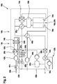
- FIG. 1 shows a schematic view of a fuel cell system 30a.
- the fuel cell system 30a comprises a fuel cell device 10a, which is provided to be operated with a fluidic fuel, in particular with natural gas. Alternatively, it is also conceivable to operate the fuel cell device 10a with another hydrocarbon containing in particular gaseous fuel such as biogas.
- the fuel cell device 10a comprises a fuel cell unit 16a.
- the fuel cell unit 16a is shown here simplified as a single fuel cell 32a. However, a fuel cell unit embodied as a fuel cell stack comprising a plurality of fuel cells is expedient.
- the fuel cell 32a is preferably embodied as a solid oxide fuel cell.
- the fuel cell 32a has an anode 34a and a cathode 36a.
- a fuel supply line 38a the fluidic fuel is fed to the fuel cell system 30a. Feed-in of the fluidic fuel can be controlled and/or regulated and/or entirely interrupted by a fuel valve 40a.
- the fuel valve 40a is preferably electro-magnetically actuatable.
- a fuel compressor 42a By means of a fuel compressor 42a a sufficient flow-rate of the fluidic fuel is ensured.
- Air is fed to a cathode 36a of the fuel cell unit 16a by means of a further compressor 44a or fan. Before entering the cathode 36a the air is preheated by a preheating unit 46a.
- the fuel cell device 10a comprises a desulfurization unit 12a. The desulfurization unit 12a is connected downstream of the fuel compressor 42a.
- the desulfurization unit 12a is provided to desulfurize the fluidic fuel.
- the fuel cell unit 10a further comprises a reformer unit 14a.
- the reformer unit 14a is provided for obtaining a hydrogen-rich fuel gas by processing the desulfurized fluidic fuel.
- the reformer unit 14a is embodied as a steam reformer unit.
- the hydrogen-rich gas leaving the reformer unit 14a is mainly fed to the anode 34a of the fuel cell unit 16a.
- the fuel cell device 10a further comprises a water supply pump 26a.
- the water supply pump 26a is provided for supplying water to the reformer unit 14a. Before entering the reformer unit 14a the water supplied is vaporized by a vaporizer unit 58a.
- the water supply pump 26a is provided for continuously supplying water to the reformer unit 14a during a normal operation of the fuel cell unit 16a.
- the water supply pump 26a is provided for a continuous conveyance of the water from a water source 60a.
- the water conveyed by the water supply pump 26a is mixed with the desulfurized fluidic fuel leaving the desulfurization unit 12a.
- materials of the desulfurization unit 12a may absorb a noxious gas, especially methane.
- the absorbed noxious gas may be desorbed, which may lead to a coking of the reformer unit 14a and/or the fuel cell unit 16a.
- the desulfurization unit 12a is provided for at least limiting a transfer of the noxious gas from the desulfurization unit 12a into the reformer unit 14a and/or into the fuel cell unit 16a when shutting down the fuel cell unit 16a.
- the desulfurization unit 12a comprises a desulfurization reactor 18a and an outlet valve 20a.
- the outlet valve 20a is arranged between the desulfurization unit 12a and the reformer unit 14a. To prevent a transfer of the noxious gas from the desulfurization unit 12a into the reformer unit 14a and/or into the fuel cell unit 16a the outlet valve 20a is provided to be closed when shutting down the fuel cell unit 16a.
- the outlet valve 20a is embodied normally closed.
- the outlet valve 20a is embodied electro-magnetically actuatable. In particular, the outlet valve 20a is kept open during a normal operation of the fuel cell unit 16a by electrical power provided by the fuel cell unit 16a.
- the desulfurization unit 12a comprises a drain valve 22a, which is provided to be opened for draining the noxious gas from the desulfurization reactor 18a when shutting down the fuel cell unit 16a.
- the drain valve 22a is arranged within a fluid line 68a, which connects an outlet of the desulfurization reactor 18a with at least one flue line or chimney 56a of the fuel cell device 10a.
- the drain valve 22a is provided to be opened automatically when shutting down the fuel cell unit 16a.
- the drain valve 22a is in particular embodied as a shut off valve.
- the drain valve 22a is embodied electro-magnetically actuatable.
- the drain valve 22a is embodied normally open.
- the drain valve 22a is kept close during a normal operation of the fuel cell unit 16a by electrical power provided by the fuel cell unit 16a.
- a power supply of the drain valve 22a is automatically interrupted.
- an exhaust gas of the anode 34a and air from the cathode 36a of the fuel cell unit 16a are fed to a combustion unit 50a in which an afterburning of combustible components remaining in the anode exhaust gas is effected.
- Thermal energy herein released is transferred, for example to a heating water circulation 52a via a heat exchanger 54a, to the reformer unit 14a, to the preheating unit 46a and/or to the vaporizer unit 58a.
- An exhaust gas is discharged via the chimney 56a.
- Figure 2 shows a further exemplary embodiment of the invention.
- the following descriptions and the drawings are essentially limited to the differences between the embodiments, wherein regarding equally designated components, in particular with regard to components with the same reference numerals, reference can be made to the drawings and/or the description of the embodiment of figure 1 .
- the letter a is attached to the reference numerals of the embodiment of figure 1 .
- the letter a is replaced by the letter b.
- FIG 2 shows a schematic view of a fuel cell system 30b.
- the fuel cell system 30b comprises a fuel cell device 10b, which is provided to be operated with a fluidic fuel, in particular with natural gas. Alternatively, it is also conceivable to operate the fuel cell device 10b with another hydrocarbon containing in particular gaseous fuel such as biogas.
- the fuel cell device 10b comprises a fuel cell unit 16b.
- the fuel cell unit 16b is shown here simplified as a single fuel cell 32b. However, a fuel cell unit embodied as a fuel cell stack comprising a plurality of fuel cells is expedient.
- the fuel cell 32b is preferably embodied as a solid oxide fuel cell.
- the fuel cell 32b has an anode 34b and a cathode 36b.
- the fluidic fuel is fed to the fuel cell system 30b. Feed-in of the fluidic fuel can be controlled and/or regulated and/or entirely interrupted by a fuel valve 40b.
- the fuel valve 40b is preferably electro-magnetically actuatable.
- a fuel compressor 42b By means of a fuel compressor 42b a sufficient flow-rate of the fluidic fuel is ensured.
- Air is fed to a cathode 36b of the fuel cell unit 16b by means of a further compressor 44b or fan. Before entering the cathode 36b the air is preheated by a preheating unit 46b.
- the fuel cell device 10b comprises a desulfurization unit 12b. The desulfurization unit 12b is connected downstream of the fuel compressor 42b.
- the desulfurization unit 12b is provided to desulfurize the fluidic fuel.
- the fuel cell unit 10b further comprises a reformer unit 14b.
- the reformer unit 14b is provided for obtaining a hydrogen-rich fuel gas by processing the desulfurized fluidic fuel.
- the reformer unit 14b is embodied as a steam reformer unit.
- the hydrogen-rich gas leaving the reformer unit 14b is mainly fed to the anode 34b of the fuel cell unit 16b.
- the fuel cell device 10b further comprises a water supply pump 26b.
- the water supply pump 26b is provided for supplying water to the reformer unit 14b. Before entering the reformer unit 14b the water supplied is vaporized by a vaporizer unit 58b.
- the water supply pump 26b is provided for continuously supplying water to the reformer unit 14b during a normal operation of the fuel cell unit 16b.
- the water supply pump 26b is provided for a continuous conveyance of the water from a water source 60b.
- the water conveyed by the water supply pump 26b is mixed with the desulfurized fluidic fuel leaving the desulfurization unit 12b.
- materials of the desulfurization unit 12b may absorb a noxious gas, especially methane.
- the absorbed noxious gas may be desorbed, which may lead to a coking of the reformer unit 14b and/or of the fuel cell unit 16b.
- the desulfurization unit 12b is provided for at least limiting a transfer of the noxious gas from the desulfurization unit 12b into the reformer unit 14b and/or into the fuel cell unit 16b when shutting down the fuel cell unit 16b.
- the desulfurization unit 12b comprises two desulfurization reactors 18b, 24b, which are connected parallel to each other and which are provided to be operated in alternation. At each point in time during a normal operation of the fuel cell unit 16b solely one of the desulfurization reactors 18b, 24b is involved in a desulfurization of the fluidic fuel. In particular, at each point in time during a normal operation of the fuel cell unit 16b a fluidic fuel flow is solely led towards one of the desulfurization reactors 18b, 24b.
- the desulfurization unit 12b respectively comprises an inlet valve 28b, 62b, an outlet valve 20b, 64b and a drain valve 22b, 66b for each desulfurization reactor.
- a changeover may be executed once, in particular when a service life end of the desulfurization reactor 18b, 24b in use is reached. In addition or alternatively, a changeover may be executed periodically, e.g. daily or monthly.
- An absorptive capacity respectively desorption capacity of each desulfurization reactor 18b, 24b regarding the noxious gas is below a sufficient amount of the noxious gas for damaging and/or destroying the reformer unit 14b and/or the fuel cell unit 16b.
- the amount of the noxious gas streaming from the desulfurization unit 12b into the reformer unit 14b and/or into the fuel cell unit 16b when shutting down the fuel cell unit 16b can be advantageously reduced.
- an exhaust gas of the anode 34a and air from the cathode 36a of the fuel cell unit 16a are fed to a combustion unit 50a in which an afterburning of combustible components remaining in the anode exhaust gas is effected.
- Thermal energy herein released is transferred, for example to a heating water circulation 52a via a heat exchanger 54a, to the reformer unit 14a, to the preheating unit 46a and/or to the vaporizer unit 58a.
- An exhaust gas is discharged via a chimney 56a.
Landscapes
- Life Sciences & Earth Sciences (AREA)
- Engineering & Computer Science (AREA)
- Manufacturing & Machinery (AREA)
- Sustainable Development (AREA)
- Sustainable Energy (AREA)
- Chemical & Material Sciences (AREA)
- Chemical Kinetics & Catalysis (AREA)
- Electrochemistry (AREA)
- General Chemical & Material Sciences (AREA)
- Fuel Cell (AREA)
Priority Applications (1)
| Application Number | Priority Date | Filing Date | Title |
|---|---|---|---|
| EP16167054.2A EP3240080B1 (de) | 2016-04-26 | 2016-04-26 | Brennstoffzellenvorrichtung |
Applications Claiming Priority (1)
| Application Number | Priority Date | Filing Date | Title |
|---|---|---|---|
| EP16167054.2A EP3240080B1 (de) | 2016-04-26 | 2016-04-26 | Brennstoffzellenvorrichtung |
Publications (2)
| Publication Number | Publication Date |
|---|---|
| EP3240080A1 true EP3240080A1 (de) | 2017-11-01 |
| EP3240080B1 EP3240080B1 (de) | 2018-12-19 |
Family
ID=55862571
Family Applications (1)
| Application Number | Title | Priority Date | Filing Date |
|---|---|---|---|
| EP16167054.2A Active EP3240080B1 (de) | 2016-04-26 | 2016-04-26 | Brennstoffzellenvorrichtung |
Country Status (1)
| Country | Link |
|---|---|
| EP (1) | EP3240080B1 (de) |
Cited By (1)
| Publication number | Priority date | Publication date | Assignee | Title |
|---|---|---|---|---|
| AT520770A1 (de) * | 2018-01-12 | 2019-07-15 | Avl List Gmbh | Entschwefelungsanordnung und Verfahren zum Austauschen einer Entschwefelungseinheit in einem Brennstoffzellensystem |
Citations (5)
| Publication number | Priority date | Publication date | Assignee | Title |
|---|---|---|---|---|
| US20030003332A1 (en) * | 2001-06-28 | 2003-01-02 | Ballard Power Systems Inc. | Self-inerting fuel processing system |
| US20030072978A1 (en) * | 2001-10-11 | 2003-04-17 | Meyer Alfred P. | Procedure for purging a fuel cell system with inert gas made from organic fuel |
| JP2010116304A (ja) * | 2008-11-14 | 2010-05-27 | Idemitsu Kosan Co Ltd | 改質装置、燃料電池システム、改質装置の運転方法 |
| EP2487742A2 (de) * | 2011-02-10 | 2012-08-15 | Aisin Seiki Kabushiki Kaisha | Brennstoffzellensystem |
| US20160036078A1 (en) * | 2014-07-29 | 2016-02-04 | Robert Bosch Gmbh | Fuel cell device |
-
2016
- 2016-04-26 EP EP16167054.2A patent/EP3240080B1/de active Active
Patent Citations (5)
| Publication number | Priority date | Publication date | Assignee | Title |
|---|---|---|---|---|
| US20030003332A1 (en) * | 2001-06-28 | 2003-01-02 | Ballard Power Systems Inc. | Self-inerting fuel processing system |
| US20030072978A1 (en) * | 2001-10-11 | 2003-04-17 | Meyer Alfred P. | Procedure for purging a fuel cell system with inert gas made from organic fuel |
| JP2010116304A (ja) * | 2008-11-14 | 2010-05-27 | Idemitsu Kosan Co Ltd | 改質装置、燃料電池システム、改質装置の運転方法 |
| EP2487742A2 (de) * | 2011-02-10 | 2012-08-15 | Aisin Seiki Kabushiki Kaisha | Brennstoffzellensystem |
| US20160036078A1 (en) * | 2014-07-29 | 2016-02-04 | Robert Bosch Gmbh | Fuel cell device |
Cited By (2)
| Publication number | Priority date | Publication date | Assignee | Title |
|---|---|---|---|---|
| AT520770A1 (de) * | 2018-01-12 | 2019-07-15 | Avl List Gmbh | Entschwefelungsanordnung und Verfahren zum Austauschen einer Entschwefelungseinheit in einem Brennstoffzellensystem |
| AT520770B1 (de) * | 2018-01-12 | 2020-04-15 | Avl List Gmbh | Entschwefelungsanordnung und Verfahren zum Austauschen einer Entschwefelungseinheit in einem Brennstoffzellensystem |
Also Published As
| Publication number | Publication date |
|---|---|
| EP3240080B1 (de) | 2018-12-19 |
Similar Documents
| Publication | Publication Date | Title |
|---|---|---|
| EP2518013B1 (de) | Wasserstoffgenerator und brennstoffzellensystem | |
| EP2518012B1 (de) | Verfahren für den betrieb einer wasserstofferzeugungsvorrichtung | |
| CN100486019C (zh) | 氢生成装置及其动作停止方法和燃料电池发电装置 | |
| JP5133165B2 (ja) | 燃料電池システム | |
| US6562502B2 (en) | Fuel cell hot zone pressure regulator | |
| WO2004086536A8 (en) | Solid oxide fuel cell with selective anode tail gas circulation | |
| US8916302B2 (en) | Method and apparatus for improving water balance in fuel cell power unit | |
| EP3240080B1 (de) | Brennstoffzellenvorrichtung | |
| US12258524B2 (en) | Fuel processing system and method for sulfur bearing fuels | |
| EP3239097B1 (de) | Brennstoffzellenelement | |
| US10847824B2 (en) | Fuel cell system including high-temperature desulfurization subsystem and method of operating the same | |
| KR102194278B1 (ko) | 조합된 수동 및 능동 흡착제 베드들을 갖는 연료 전지 시스템 | |
| US10483575B2 (en) | Fuel cell device | |
| JP5148164B2 (ja) | 液体燃料処理装置および燃料電池発電システム | |
| JP6523841B2 (ja) | 燃料電池システム | |
| JP2009076392A (ja) | 液体燃料電池発電システム | |
| JP5117690B2 (ja) | 燃料電池システム | |
| JP2010024402A (ja) | 燃料電池発電システムおよびそれに用いる脱硫器 | |
| JP2014058426A (ja) | 水素生成装置及び燃料電池システム | |
| WO2005005313A1 (ja) | 燃料処理装置及びその方法 | |
| JP5466871B2 (ja) | 燃料電池用改質装置 | |
| EP4497805A1 (de) | Entschwefelungssysteme enthaltend gemischte medien und brennstoffzellensysteme damit | |
| US20250038237A1 (en) | Mixed media desulfurization systems and fuel cell systems including the same | |
| CN101346175A (zh) | 燃料电池用燃料处理系统中硫中毒的贵金属催化剂的再生 | |
| JP4383972B2 (ja) | 脱硫システム及びその停止方法 |
Legal Events
| Date | Code | Title | Description |
|---|---|---|---|
| PUAI | Public reference made under article 153(3) epc to a published international application that has entered the european phase |
Free format text: ORIGINAL CODE: 0009012 |
|
| STAA | Information on the status of an ep patent application or granted ep patent |
Free format text: STATUS: THE APPLICATION HAS BEEN PUBLISHED |
|
| AK | Designated contracting states |
Kind code of ref document: A1 Designated state(s): AL AT BE BG CH CY CZ DE DK EE ES FI FR GB GR HR HU IE IS IT LI LT LU LV MC MK MT NL NO PL PT RO RS SE SI SK SM TR |
|
| AX | Request for extension of the european patent |
Extension state: BA ME |
|
| STAA | Information on the status of an ep patent application or granted ep patent |
Free format text: STATUS: REQUEST FOR EXAMINATION WAS MADE |
|
| 17P | Request for examination filed |
Effective date: 20180425 |
|
| RBV | Designated contracting states (corrected) |
Designated state(s): AL AT BE BG CH CY CZ DE DK EE ES FI FR GB GR HR HU IE IS IT LI LT LU LV MC MK MT NL NO PL PT RO RS SE SI SK SM TR |
|
| GRAP | Despatch of communication of intention to grant a patent |
Free format text: ORIGINAL CODE: EPIDOSNIGR1 |
|
| STAA | Information on the status of an ep patent application or granted ep patent |
Free format text: STATUS: GRANT OF PATENT IS INTENDED |
|
| RIC1 | Information provided on ipc code assigned before grant |
Ipc: H01M 8/0662 20160101ALI20180614BHEP Ipc: H01M 8/124 20160101ALN20180614BHEP Ipc: H01M 8/04082 20160101ALI20180614BHEP Ipc: H01M 8/0612 20160101AFI20180614BHEP Ipc: H01M 8/04228 20160101ALI20180614BHEP |
|
| INTG | Intention to grant announced |
Effective date: 20180711 |
|
| GRAS | Grant fee paid |
Free format text: ORIGINAL CODE: EPIDOSNIGR3 |
|
| GRAA | (expected) grant |
Free format text: ORIGINAL CODE: 0009210 |
|
| STAA | Information on the status of an ep patent application or granted ep patent |
Free format text: STATUS: THE PATENT HAS BEEN GRANTED |
|
| AK | Designated contracting states |
Kind code of ref document: B1 Designated state(s): AL AT BE BG CH CY CZ DE DK EE ES FI FR GB GR HR HU IE IS IT LI LT LU LV MC MK MT NL NO PL PT RO RS SE SI SK SM TR |
|
| REG | Reference to a national code |
Ref country code: GB Ref legal event code: FG4D |
|
| REG | Reference to a national code |
Ref country code: CH Ref legal event code: EP |
|
| REG | Reference to a national code |
Ref country code: IE Ref legal event code: FG4D |
|
| REG | Reference to a national code |
Ref country code: DE Ref legal event code: R096 Ref document number: 602016008336 Country of ref document: DE |
|
| REG | Reference to a national code |
Ref country code: AT Ref legal event code: REF Ref document number: 1079651 Country of ref document: AT Kind code of ref document: T Effective date: 20190115 |
|
| REG | Reference to a national code |
Ref country code: NL Ref legal event code: MP Effective date: 20181219 |
|
| PG25 | Lapsed in a contracting state [announced via postgrant information from national office to epo] |
Ref country code: LV Free format text: LAPSE BECAUSE OF FAILURE TO SUBMIT A TRANSLATION OF THE DESCRIPTION OR TO PAY THE FEE WITHIN THE PRESCRIBED TIME-LIMIT Effective date: 20181219 Ref country code: HR Free format text: LAPSE BECAUSE OF FAILURE TO SUBMIT A TRANSLATION OF THE DESCRIPTION OR TO PAY THE FEE WITHIN THE PRESCRIBED TIME-LIMIT Effective date: 20181219 Ref country code: BG Free format text: LAPSE BECAUSE OF FAILURE TO SUBMIT A TRANSLATION OF THE DESCRIPTION OR TO PAY THE FEE WITHIN THE PRESCRIBED TIME-LIMIT Effective date: 20190319 Ref country code: NO Free format text: LAPSE BECAUSE OF FAILURE TO SUBMIT A TRANSLATION OF THE DESCRIPTION OR TO PAY THE FEE WITHIN THE PRESCRIBED TIME-LIMIT Effective date: 20190319 Ref country code: LT Free format text: LAPSE BECAUSE OF FAILURE TO SUBMIT A TRANSLATION OF THE DESCRIPTION OR TO PAY THE FEE WITHIN THE PRESCRIBED TIME-LIMIT Effective date: 20181219 Ref country code: FI Free format text: LAPSE BECAUSE OF FAILURE TO SUBMIT A TRANSLATION OF THE DESCRIPTION OR TO PAY THE FEE WITHIN THE PRESCRIBED TIME-LIMIT Effective date: 20181219 |
|
| REG | Reference to a national code |
Ref country code: LT Ref legal event code: MG4D |
|
| REG | Reference to a national code |
Ref country code: AT Ref legal event code: MK05 Ref document number: 1079651 Country of ref document: AT Kind code of ref document: T Effective date: 20181219 |
|
| PG25 | Lapsed in a contracting state [announced via postgrant information from national office to epo] |
Ref country code: RS Free format text: LAPSE BECAUSE OF FAILURE TO SUBMIT A TRANSLATION OF THE DESCRIPTION OR TO PAY THE FEE WITHIN THE PRESCRIBED TIME-LIMIT Effective date: 20181219 Ref country code: SE Free format text: LAPSE BECAUSE OF FAILURE TO SUBMIT A TRANSLATION OF THE DESCRIPTION OR TO PAY THE FEE WITHIN THE PRESCRIBED TIME-LIMIT Effective date: 20181219 Ref country code: AL Free format text: LAPSE BECAUSE OF FAILURE TO SUBMIT A TRANSLATION OF THE DESCRIPTION OR TO PAY THE FEE WITHIN THE PRESCRIBED TIME-LIMIT Effective date: 20181219 Ref country code: GR Free format text: LAPSE BECAUSE OF FAILURE TO SUBMIT A TRANSLATION OF THE DESCRIPTION OR TO PAY THE FEE WITHIN THE PRESCRIBED TIME-LIMIT Effective date: 20190320 |
|
| PG25 | Lapsed in a contracting state [announced via postgrant information from national office to epo] |
Ref country code: NL Free format text: LAPSE BECAUSE OF FAILURE TO SUBMIT A TRANSLATION OF THE DESCRIPTION OR TO PAY THE FEE WITHIN THE PRESCRIBED TIME-LIMIT Effective date: 20181219 |
|
| PG25 | Lapsed in a contracting state [announced via postgrant information from national office to epo] |
Ref country code: PL Free format text: LAPSE BECAUSE OF FAILURE TO SUBMIT A TRANSLATION OF THE DESCRIPTION OR TO PAY THE FEE WITHIN THE PRESCRIBED TIME-LIMIT Effective date: 20181219 Ref country code: IT Free format text: LAPSE BECAUSE OF FAILURE TO SUBMIT A TRANSLATION OF THE DESCRIPTION OR TO PAY THE FEE WITHIN THE PRESCRIBED TIME-LIMIT Effective date: 20181219 Ref country code: PT Free format text: LAPSE BECAUSE OF FAILURE TO SUBMIT A TRANSLATION OF THE DESCRIPTION OR TO PAY THE FEE WITHIN THE PRESCRIBED TIME-LIMIT Effective date: 20190419 Ref country code: ES Free format text: LAPSE BECAUSE OF FAILURE TO SUBMIT A TRANSLATION OF THE DESCRIPTION OR TO PAY THE FEE WITHIN THE PRESCRIBED TIME-LIMIT Effective date: 20181219 Ref country code: CZ Free format text: LAPSE BECAUSE OF FAILURE TO SUBMIT A TRANSLATION OF THE DESCRIPTION OR TO PAY THE FEE WITHIN THE PRESCRIBED TIME-LIMIT Effective date: 20181219 |
|
| PG25 | Lapsed in a contracting state [announced via postgrant information from national office to epo] |
Ref country code: RO Free format text: LAPSE BECAUSE OF FAILURE TO SUBMIT A TRANSLATION OF THE DESCRIPTION OR TO PAY THE FEE WITHIN THE PRESCRIBED TIME-LIMIT Effective date: 20181219 Ref country code: IS Free format text: LAPSE BECAUSE OF FAILURE TO SUBMIT A TRANSLATION OF THE DESCRIPTION OR TO PAY THE FEE WITHIN THE PRESCRIBED TIME-LIMIT Effective date: 20190419 Ref country code: EE Free format text: LAPSE BECAUSE OF FAILURE TO SUBMIT A TRANSLATION OF THE DESCRIPTION OR TO PAY THE FEE WITHIN THE PRESCRIBED TIME-LIMIT Effective date: 20181219 Ref country code: SM Free format text: LAPSE BECAUSE OF FAILURE TO SUBMIT A TRANSLATION OF THE DESCRIPTION OR TO PAY THE FEE WITHIN THE PRESCRIBED TIME-LIMIT Effective date: 20181219 Ref country code: SK Free format text: LAPSE BECAUSE OF FAILURE TO SUBMIT A TRANSLATION OF THE DESCRIPTION OR TO PAY THE FEE WITHIN THE PRESCRIBED TIME-LIMIT Effective date: 20181219 |
|
| REG | Reference to a national code |
Ref country code: DE Ref legal event code: R097 Ref document number: 602016008336 Country of ref document: DE |
|
| PLBE | No opposition filed within time limit |
Free format text: ORIGINAL CODE: 0009261 |
|
| STAA | Information on the status of an ep patent application or granted ep patent |
Free format text: STATUS: NO OPPOSITION FILED WITHIN TIME LIMIT |
|
| PG25 | Lapsed in a contracting state [announced via postgrant information from national office to epo] |
Ref country code: AT Free format text: LAPSE BECAUSE OF FAILURE TO SUBMIT A TRANSLATION OF THE DESCRIPTION OR TO PAY THE FEE WITHIN THE PRESCRIBED TIME-LIMIT Effective date: 20181219 Ref country code: DK Free format text: LAPSE BECAUSE OF FAILURE TO SUBMIT A TRANSLATION OF THE DESCRIPTION OR TO PAY THE FEE WITHIN THE PRESCRIBED TIME-LIMIT Effective date: 20181219 |
|
| 26N | No opposition filed |
Effective date: 20190920 |
|
| REG | Reference to a national code |
Ref country code: CH Ref legal event code: PL |
|
| REG | Reference to a national code |
Ref country code: BE Ref legal event code: MM Effective date: 20190430 |
|
| PG25 | Lapsed in a contracting state [announced via postgrant information from national office to epo] |
Ref country code: LU Free format text: LAPSE BECAUSE OF NON-PAYMENT OF DUE FEES Effective date: 20190426 Ref country code: MC Free format text: LAPSE BECAUSE OF FAILURE TO SUBMIT A TRANSLATION OF THE DESCRIPTION OR TO PAY THE FEE WITHIN THE PRESCRIBED TIME-LIMIT Effective date: 20181219 |
|
| PG25 | Lapsed in a contracting state [announced via postgrant information from national office to epo] |
Ref country code: CH Free format text: LAPSE BECAUSE OF NON-PAYMENT OF DUE FEES Effective date: 20190430 Ref country code: LI Free format text: LAPSE BECAUSE OF NON-PAYMENT OF DUE FEES Effective date: 20190430 |
|
| PG25 | Lapsed in a contracting state [announced via postgrant information from national office to epo] |
Ref country code: FR Free format text: LAPSE BECAUSE OF NON-PAYMENT OF DUE FEES Effective date: 20190430 Ref country code: SI Free format text: LAPSE BECAUSE OF FAILURE TO SUBMIT A TRANSLATION OF THE DESCRIPTION OR TO PAY THE FEE WITHIN THE PRESCRIBED TIME-LIMIT Effective date: 20181219 Ref country code: BE Free format text: LAPSE BECAUSE OF NON-PAYMENT OF DUE FEES Effective date: 20190430 |
|
| PG25 | Lapsed in a contracting state [announced via postgrant information from national office to epo] |
Ref country code: TR Free format text: LAPSE BECAUSE OF FAILURE TO SUBMIT A TRANSLATION OF THE DESCRIPTION OR TO PAY THE FEE WITHIN THE PRESCRIBED TIME-LIMIT Effective date: 20181219 |
|
| PG25 | Lapsed in a contracting state [announced via postgrant information from national office to epo] |
Ref country code: IE Free format text: LAPSE BECAUSE OF NON-PAYMENT OF DUE FEES Effective date: 20190426 |
|
| GBPC | Gb: european patent ceased through non-payment of renewal fee |
Effective date: 20200426 |
|
| PG25 | Lapsed in a contracting state [announced via postgrant information from national office to epo] |
Ref country code: GB Free format text: LAPSE BECAUSE OF NON-PAYMENT OF DUE FEES Effective date: 20200426 |
|
| PG25 | Lapsed in a contracting state [announced via postgrant information from national office to epo] |
Ref country code: CY Free format text: LAPSE BECAUSE OF FAILURE TO SUBMIT A TRANSLATION OF THE DESCRIPTION OR TO PAY THE FEE WITHIN THE PRESCRIBED TIME-LIMIT Effective date: 20181219 |
|
| PG25 | Lapsed in a contracting state [announced via postgrant information from national office to epo] |
Ref country code: HU Free format text: LAPSE BECAUSE OF FAILURE TO SUBMIT A TRANSLATION OF THE DESCRIPTION OR TO PAY THE FEE WITHIN THE PRESCRIBED TIME-LIMIT; INVALID AB INITIO Effective date: 20160426 Ref country code: MT Free format text: LAPSE BECAUSE OF FAILURE TO SUBMIT A TRANSLATION OF THE DESCRIPTION OR TO PAY THE FEE WITHIN THE PRESCRIBED TIME-LIMIT Effective date: 20181219 |
|
| PG25 | Lapsed in a contracting state [announced via postgrant information from national office to epo] |
Ref country code: MK Free format text: LAPSE BECAUSE OF FAILURE TO SUBMIT A TRANSLATION OF THE DESCRIPTION OR TO PAY THE FEE WITHIN THE PRESCRIBED TIME-LIMIT Effective date: 20181219 |
|
| P01 | Opt-out of the competence of the unified patent court (upc) registered |
Effective date: 20230525 |
|
| PGFP | Annual fee paid to national office [announced via postgrant information from national office to epo] |
Ref country code: DE Payment date: 20250430 Year of fee payment: 10 |