EP3240104A1 - Vorrichtung zum positionsgerechten befestigen einer antennenanordnung - Google Patents
Vorrichtung zum positionsgerechten befestigen einer antennenanordnung Download PDFInfo
- Publication number
- EP3240104A1 EP3240104A1 EP17168712.2A EP17168712A EP3240104A1 EP 3240104 A1 EP3240104 A1 EP 3240104A1 EP 17168712 A EP17168712 A EP 17168712A EP 3240104 A1 EP3240104 A1 EP 3240104A1
- Authority
- EP
- European Patent Office
- Prior art keywords
- recess
- clamping plate
- antenna
- connection means
- bottom plate
- Prior art date
- Legal status (The legal status is an assumption and is not a legal conclusion. Google has not performed a legal analysis and makes no representation as to the accuracy of the status listed.)
- Granted
Links
Images





Classifications
-
- H—ELECTRICITY
- H01—ELECTRIC ELEMENTS
- H01Q—ANTENNAS, i.e. RADIO AERIALS
- H01Q1/00—Details of, or arrangements associated with, antennas
- H01Q1/27—Adaptation for use in or on movable bodies
- H01Q1/32—Adaptation for use in or on road or rail vehicles
- H01Q1/325—Adaptation for use in or on road or rail vehicles characterised by the location of the antenna on the vehicle
- H01Q1/3275—Adaptation for use in or on road or rail vehicles characterised by the location of the antenna on the vehicle mounted on a horizontal surface of the vehicle, e.g. on roof, hood, trunk
-
- H—ELECTRICITY
- H01—ELECTRIC ELEMENTS
- H01Q—ANTENNAS, i.e. RADIO AERIALS
- H01Q1/00—Details of, or arrangements associated with, antennas
- H01Q1/12—Supports; Mounting means
- H01Q1/1207—Supports; Mounting means for fastening a rigid aerial element
- H01Q1/1214—Supports; Mounting means for fastening a rigid aerial element through a wall
Definitions
- the invention relates to a device for positionally fixing an antenna assembly to a surface having a recess for antenna connection means formed as plugs or sockets, wherein the antenna assembly has a bottom plate from which connecting means to the recess extending, which secured against loss clamping plate and a screw or a bolt comprise such that the clamping plate by means of screw or bolt in the direction of the base plate is movable and braced, according to the preamble of claim 1.
- a roof antenna which has a bottom plate for receiving antenna elements.
- the antenna elements are covered by a connectable to the bottom plate antenna cover.
- the previously known roof antenna should be mounted on a cutout, in particular a roof opening having mounting surface, in particular a vehicle roof by means of screw.
- the connecting means are formed as an axially and radially movable clamping part between the bottom plate of the roof antenna and the mounting surface.
- the actual attachment is therefore by means of bracing, preferably by screwing.
- the fastening process is realized via an initially axial and then radial movement of the clamping part. By turning the screw, the distance between the clamping plate and the bottom plate can be changed with the result of the desired attachment and pinching corresponding portions of the roof of the body of the vehicle.
- the well-known clamping part has an outer contour, which makes it possible to pass this when placing the roof antenna through a corresponding roof opening in the mounting surface and then by twisting or moving the Clamping part by a defined amount to bring this under the mounting surface into engagement, so that the clamping member can not be removed again against the direction of insertion from the roof cutout.
- should be particularly triangular, oval, elliptical or other polygonal or wedge-shaped outer contours of the clamping part are suitable.
- German utility model DE 20 2013 010 506 U1 is a generic device for positionally correct mounting an antenna assembly known.
- the width of the recess is according to DE 20 2013 010 506 U1 at least in sections substantially equal to the width of the clamping plate for fixing the antenna.
- the length of the recess is smaller than the length of the clamping plate such that a circular arc-shaped immersion of the connecting means, ie the clamping plate and the screw or the bolt into the recess and a subsequent bracing can be realized.
- the mentioned arcuate immersion with the clamping plate first into the recess followed by moving into the recess and moving counter to the immersion in the sense of pivoting back can be completely contactless relative to the surface of a body in which the recess is made.
- connection means for the antenna must be passed through the clamping plate.
- the clamping plate, the space for the connection means quasi covering, formed.
- antenna connection means are preferably designed as plugs or sockets, in particular as so-called FAKRA connectors, or connection cables.
- the antenna arrangement has a bottom plate, from which connecting means extend in the direction of the recess.
- These connecting means comprise a secured against loss clamping plate and a screw or a bolt or the like means such that the clamping plate by means of screw or bolt in the direction of the bottom plate is movable and braced.
- This tension fixing the antenna assembly on the aforementioned vehicle roof or the like surface is effected.
- the antenna has an antenna housing, which is preferably designed in the form of a so-called shark fin or similar streamlined.
- the antenna housing and the entire antenna arrangement has a longitudinal axis, which runs parallel to the vehicle longitudinal axis in the assembled state.
- the extent of the antenna arrangement or the housing and the bottom plate is realized such that the length dimensions are greater than the width dimensions, so that on the one hand the different antenna configurations can be accommodated and united for different frequency bands in the housing and on the other hand the necessary streamlined shape to avoid wind noise is guaranteed.
- connection means as plugs, sockets or cables, z. B. FAKRA sockets are executed. This means that after mounting the antenna on a vehicle roof care must be taken that the connection means, in particular the FAKRA sockets, are freely accessible from the rear or below, in order to realize the necessary connections. This also applies to the necessary power supply for normally active antennas.
- the width of the recess to be executed in the vehicle roof is smaller than the width of the clamping plate, with the aid of which the antenna is fixed.
- the length of the recess is greater than the length of the clamping plate such that a lateral einschwenkendes immersion of the connecting means with clamping plate in the recess and a displacement in the direction of Longitudinal axis of the recess and the subsequent bracing can be realized.
- a group of plugs or sockets of the antenna connection means is located within the recess and freely accessible.
- the plug or socket in a first region of the bottom plate and it is the clamping plate with screw or bolt in a laterally spaced from the first plate region second region of the bottom plate formed such that the desired free access to the connection means is present.
- connection means is separated from the area of the clamping plate and spaced apart. A superposition of these two areas with the disadvantages described above is avoided.
- connection means i. Bushings and / or plugs available, which is due to the fact and requirement that the number of antennas to be housed in the antenna housing with appropriate connections due to a variety of wireless communication solutions is subject to a constant increase.
- the recess in the mounting surface in particular a vehicle body, is formed as a slot or has a slot shape, wherein on the longitudinal axis of the slot the recess merges into a subsequent opening for a twist protection or the recess is a spaced Associated opening for a known twist.
- the extensions are formed so that selbige are approximated at least in sections of the contour of the hole pattern, in particular the oblong hole recess or this Approximate the contour.
- the first region of the base plate has two spaced-apart partial regions, the second region of the clamping plate being formed in the spacer space.
- the recess has a hole pattern in oblong shape with sidecut.
- the clamping plate is positioned in the fastening state in the region of the sidecut.
- a substantially circular recess which has a predetermined diameter.
- the clamping plate is longer than the diameter of the recess by a predetermined amount.
- the width of the clamping plate is smaller by a predetermined amount than the diameter of the recess.
- the resulting hereby lateral gap between the clamping plate and recess serves to accommodate connection cables or also connection sockets.
- the cables are initially led with or without plug through the hole pattern.
- the antenna assembly is angled with clamping plate in Klemmplattenlnaturescardi and guided on one side through the hole pattern.
- the extent of the greater length of the clamping plate relative to the diameter of the recess determines the degree of angling one-sided lead through the hole pattern.
- the antenna is slightly pushed back against the direction of insertion. This takes place until the antenna arrangement is seated and an optional anti-twist device engages in a further recess in the vehicle roof.
- the tightening of the clamping plate by means of screw or bolt in the direction of the bottom plate until the desired clamping and frictional connection is present.
- the clamping plate has recesses on its longitudinal sides, which receive and lead the connecting cables at least partially.
- the width of the clamping plate it is not necessary to reduce the width of the clamping plate completely by the amount of connecting cable leading to, since at least a partial cross-section of the corresponding cable is received by the respective recess in the clamping plate.
- the antenna arrangement shown in the embodiments starts from a mounting surface 1, in particular a vehicle roof.
- the attachment surface 1 has a recess 2 for antenna connection means 10.
- the width B of the recess 2 is smaller than the width of the clamping plate 6.
- the length L of the recess 2 is greater than the length of the clamping plate 6, in such a way that a pivoting immersion of the connecting means with clamping plate 6 in the recess 2 possible is, when reached, positionally correct fastening end the group of plugs or sockets 10 of the antenna connection means within the recess 2 is located and freely accessible, as in particular the Fig. 1 and the Fig. 9 demonstrate.
- the antenna arrangement is according to Fig. 2 above the hole pattern, that is positioned over the recess 2.
- the next step is according to Fig. 3 a pivoting with immersion of a first clamping plate end in the recess 2.
- Fig. 4 pushed the clamp in the tilted or angled state laterally through the recess 2.
- the clamping plate is based on the Fig. 4 opposite side (see Fig. 5 ) through the recess, ie guided by the hole pattern.
- the screw or the bolt 7 can be actuated, and indeed until the clamping plate 6 comes into contact with the underside of the surface 1, so that the desired surface pressure and thus fixing the antenna assembly adjusts.
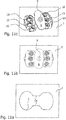
- the basic embodiment of the recess 2 in the form of a slot-like hole pattern is in the Fig. 10a ).
- This form of the hole pattern is preferably used in the original equipment or the motor vehicle manufacture according to the assembly of a corresponding antenna.
- the hole pattern according to Fig. 10b ) can be used for retrofit purposes.
- the given in this case circular recess is easier to carry out in the retrofit case by workshops or laymen.
- Possible disadvantages of a slightly longer period of time when swiveling in and finding the exact position with respect to clamping plate and their location below the surface 1 can be accepted.
- the hole pattern according to Fig. 10b is shown as a circular hole pattern 2. Spaced from the circular hole pattern 2 is a smaller, here also exemplary circular recess 12 for receiving an anti-rotation nose, which extends from the bottom plate of the antenna assembly in the direction of mounting surface.
- the Fig. 11a ) to c) demonstrates a further embodiment of the embodiment of the device according to the invention, wherein it is also ensured that there, where the clamping plate 6 is executed, no obstruction related to the accessibility of sockets for antenna connection means is present.
- the recess 2 according to Fig. 11a also has the shape of a slot from the basic structure, but with a sidecut 14 quasi in the central area.
- the first region of the bottom plate 3 of the antenna arrangement has two spaced partial regions, wherein the second region is formed with clamping plate 6 in the spacer space.
- the hole patterns for the standard equipment or for retrofitting in the aftermarket business are the same in terms of size.
- the entire antenna is pivoted in view of the features according to the invention as explained above.
- the clamping plate or nut and screw is disassembled and placed the antenna on the recess and then screwed.
- all hole patterns can be used.
- the antenna arrangement is usually mounted or pivoted on the shortest side of the bottom plate to the attachment center point.
- the recess can be kept small and the screw for fixing short, as this does not protrude too far into the passenger compartment when mounted outdoors or in the housing when mounted inside.
- a positive side effect is also that the height of the housing can be reduced, resulting in weight reduction and material savings.
- FIGS. 12 to 16 let the assembly process according to the second embodiment of the invention are explained in more detail.
- An antenna assembly 13 is to be mounted on a mounting surface 1, for example a vehicle roof.
- the antenna connection means 10 are formed here as a cable, at the ends are not shown plugs or sockets.
- the antenna arrangement 13 is angled, wherein the clamping plate 6 follows the angling. In this way, the clamping plate can be pivoted into the recess 2 ( Fig. 13 ).
- the longitudinal extent of the clamping plate 6 is greater than the diameter of the circular recess 2 by a defined amount.
- the width of the clamping plate 6 is thus chosen smaller than the diameter of the recess 2 for mounting in the recess 2 with a circular cross-section.
- the clamping plate 6 on its longitudinal sides where the antenna connection means 10 abut have recesses, for. B. such recesses, which are adapted to the cross-sectional area of the respective connection means 10. This results in a further guidance and secure fixing of the connection means, so that a Damage to this in later operation, z. B. caused by metal edges in the recess are excluded.
- the bottom plate 3 of the antenna arrangement 13 comes to rest on the upper side of the attachment surface 1.
Landscapes
- Engineering & Computer Science (AREA)
- Remote Sensing (AREA)
- Support Of Aerials (AREA)
Abstract
Description
- Die Erfindung betrifft eine Vorrichtung zum positionsgerechten Befestigen einer Antennenanordnung an einer Fläche, welche eine Aussparung für Antennenanschlussmittel, ausgebildet als Stecker oder Buchsen, aufweist, wobei die Antennenanordnung eine Bodenplatte besitzt, von der sich Verbindungsmittel zur Aussparung erstrecken, welche eine gegen Verlust gesicherte Klemmplatte und eine Schraube oder einen Schraubbolzen umfassen derart, dass die Klemmplatte mittels Schraube oder Schraubbolzen in Richtung Bodenplatte beweg- und verspannbar ist, gemäß Oberbegriff des Anspruchs 1.
- Aus der
DE 10 2005 044 618 A1 ist eine Dachantenne vorbekannt, welche eine Bodenplatte zur Aufnahme von Antennenelementen aufweist. Die Antennenelemente sind von einer mit der Bodenplatte verbindbaren Antennenhaube abgedeckt. Die vorbekannte Dachantenne soll auf einer einen Ausschnitt, insbesondere einen Dachausschnitt aufweisende Befestigungsfläche, insbesondere einem Fahrzeugdach mittels Schraubverbindung montierbar sein. - Gemäß der
DE 10 2005 044 618 A1 sind die Verbindungsmittel als ein zwischen der Bodenplatte der Dachantenne und der Befestigungsfläche axial und radial bewegbares Klemmteil ausgebildet. Die eigentliche Befestigung erfolgt demnach mittels Verspannung, vorzugsweise durch Verschraubung. Der Befestigungsvorgang wird über eine zunächst axiale und dann radiale Bewegung des Klemmteils realisiert. Mittels Verdrehen der Schraube kann der Abstand zwischen Klemmplatte und Bodenplatte verändert werden mit der Folge der gewünschten Befestigung und einem Einklemmen entsprechender Abschnitte der Dachhaut der Karosserie des Fahrzeugs. Das bekannte Klemmteil hat eine Außenkontur, die es ermöglicht, dieses beim Aufsetzen der Dachantenne durch einen korrespondierenden Dachausschnitt in der Befestigungsfläche hindurchzuführen und danach durch Verdrehen oder Verschieben des Klemmteils um einen definierten Betrag dieses unter der Befestigungsfläche in Eingriff zu bringen, so dass das Klemmteil nicht wieder entgegen der Einführrichtung aus dem Dachausschnitt entfernt werden kann. Unter diesem Aspekt sollen sich besonder dreieckige, ovale, elliptische oder sonstige polygonale oder keilförmige Außenkonturen des Klemmteils eignen. - Die beim Stand der Technik notwendige, zunächst axiale und dann radiale Bewegung des Klemmteils erfordert eine genaue Handlungsvorschrift, was bei einer grundsätzlich schnellen und zügigen Montage nachteilig ist. Darüber hinaus ist eine radiale Bewegung, insbesondere ein Verdrehen einer derartig ausgestalteten Dachantenne auf einer Fahrzeugkarosserie mit der Gefahr einer Beschädigung der Karosserieoberfläche, insbesondere einer dort bereits aufgebrachten Lackschicht verbunden.
- Aus dem deutschen Gebrauchsmuster
DE 20 2013 010 506 U1 ist eine gattungsgemäße Vorrichtung zum positionsgerechten Befestigen einer Antennenanordnung bekannt. - Bei diesem Stand der Technik ist es Aufgabe, den Befestigungsvorgang mit Hilfe einer einfachen, quasi intuitiven Bewegungsroutine abzuwickeln, so dass sich der Montageaufwand verringert und hierdurch eine Zeit- und Kostenersparnis die Folge ist. Diesbezüglich ist die Breite der Aussparung gemäß
DE 20 2013 010 506 U1 mindestens abschnittsweise im Wesentlichen gleich der Breite der Klemmplatte zur Befestigung der Antenne. Darüber hinaus ist die Länge der Aussparung kleiner als die Länge der Klemmplatte derart, dass ein kreisbogenförmiges Eintauchen der Verbindungsmittel, d.h. der Klemmplatte und der Schraube bzw. dem Schraubbolzen in die Aussparung und ein anschließendes Verspannen realisierbar ist. Das erwähnte kreisbogenförmige Eintauchen mit der Klemmplatte voran in die Aussparung mit sich anschließendem Hineinbewegen in die Aussparung sowie ein Bewegen entgegen der Eintauchrichtung im Sinne eines Zurückschwenkens kann völlig berührungsfrei bezogen auf die Oberfläche einer Karosserie, in der sich die Aussparung befindet, erfolgen. - Bei der Lösung des geschilderten Standes der Technik ist es jedoch nachteilig, dass die Anschlussmittel für die Antenne durch die Klemmplatte hindurchgeführt werden müssen. Insofern ist die Klemmplatte, den Raum für die Anschlussmittel quasi überdeckend, ausgebildet. Mit einer solchen Lösung kann zwar die Größe der Aussparung, welche in die Karosserieoberfläche eingebracht werden muss, begrenzt werden, jedoch ist eine reduzierte Stabilität der Klemmplatte selbst und eine begrenzte Anzahl der Ausführung von Anschlusselementen, insbesondere Buchsen oder Steckern die Folge.
- Aus dem Vorgenannten ist es daher Aufgabe der Erfindung, eine weiterentwickelte Vorrichtung zum positionsgerechten Befestigen einer Antennenanordnung an einer Fläche, welche eine Aussparung für Antennenanschlusselemente, ausgebildet als Stecker oder Buchsen und/oder Kabel, aufweist, anzugeben, wobei einerseits wiederum eine intuitive zügige sichere und einfache Vornahme des Befestigungsablaufs realisierbar ist sowie gleichzeitig eine möglichst große Fläche zur Anordnung der zum Antennenanschluss notwendigen Stecker, Buchsen oder Kabel gegeben ist, sowie die Klemmplatte auch bei gegebenenfalls kleinerer Klemmfläche die notwendigen Kräfte zum Fixieren der Antenne sicher zum Verdrahten aufnehmen kann.
- Die Lösung der Aufgabe der Erfindung erfolgt durch eine Vorrichtung gemäß der Merkmalskombination nach Anspruch 1 oder 8, wobei die Unteransprüche mindestens zweckmäßige Ausgestaltungen und Weiterbildungen umfassen.
- Es wird demnach von einer Vorrichtung zum positionsgerechten Befestigen einer Antennenanordnung an einer Fläche, insbesondere einer Karosserie eines Fahrzeugs ausgegangen, welche eine Aussparung für die notwendigen Antennenanschlussmittel aufweist. Diese Antennenanschlussmittel sind bevorzugt als Stecker oder Buchsen, insbesondere als sogenannte FAKRA-Verbinder, oder Anschlusskabel ausgeführt.
- Die Antennenanordnung besitzt eine Bodenplatte, von der sich Verbindungsmittel in Richtung Aussparung erstrecken. Diese Verbindungsmittel umfassen eine gegen Verlust gesicherte Klemmplatte und eine Schraube oder einen Schraubbolzen bzw. dergleichen Mittel derart, dass die Klemmplatte mittels Schraube oder Schraubbolzen in Richtung Bodenplatte beweg- und verspannbar ist. Über diese Verspannung wird ein Fixieren der Antennenanordnung am vorerwähnten Fahrzeugdach oder dergleichen Fläche bewirkt.
- Die Antenne weist ein Antennengehäuse auf, das bevorzugt in Form einer sogenannten Haifischflosse oder ähnlich strömungsgünstig ausgebildet ist. Üblicherweise weist das Antennengehäuse und die gesamte Antennenanordnung eine Längsachse auf, welche im Montagezustand parallel zur Fahrzeuglängsachse verläuft. Die Ausdehnung der Antennenanordnung bzw. des Gehäuses und der Bodenplatte ist derart realisiert, dass die Längenmaße größer als die Breitenmaße sind, so dass einerseits die verschiedenen Antennenkonfigurationen für unterschiedliche Frequenzbänder im Gehäuse untergebracht und vereint werden können sowie andererseits die notwendige strömungsgünstige Form zur Vermeidung von Windgeräuschen gewährleistet wird.
- Bei der erfindungsgemäßen Vorrichtung wird davon ausgegangen, dass die Anschlussmittel als Stecker, Buchsen oder Kabel, z. B. FAKRA-Buchsen ausgeführt sind. Dies bedeutet, dass nach Montage der Antenne auf einem Fahrzeugdach dafür Sorge getragen werden muss, dass die Anschlussmittel, insbesondere die FAKRA-Buchsen, frei von hinten bzw. unten zugänglich sind, um die notwendigen Steckverbindungen zu realisieren. Dies gilt auch für die notwendige Stromversorgung bei üblicherweise aktiv ausgeführten Antennen.
- Gemäß einer ersten Ausführungsform der Erfindung ist die Breite der im Fahrzeugdach auszuführenden Aussparung kleiner als die Breite der Klemmplatte, mit deren Hilfe die Antenne fixiert wird. Die Länge der Aussparung ist hingegen größer als die Länge der Klemmplatte derart, dass ein seitliches einschwenkendes Eintauchen der Verbindungsmittel mit Klemmplatte in die Aussparung und ein Verschieben in Richtung der Längsachse der Aussparung sowie das anschließende Verspannen realisierbar ist.
- Bei erreichter positionsgerechter Befestigungslage ist dann eine Gruppe von Steckern oder Buchsen der Antennenanschlussmittel innerhalb der Aussparung befindlich und frei zugänglich.
- In Weiterbildung der Erfindung sind die Stecker oder Buchsen in einem ersten Bereich der Bodenplatte und es ist die Klemmplatte mit Schraube oder Schraubbolzen in einem, vom ersten Plattenbereich lateral beabstandeten zweiten Bereich der Bodenplatte ausgebildet derart, dass der gewünschte freie Zugang zu den Anschlussmitteln vorliegt.
- Es ist also der Bereich der Anordnung der Anschlussmittel von dem Bereich der Klemmplatte getrennt und beabstandet. Ein Übereinanderliegen dieser beiden Bereiche mit den eingangs geschilderten Nachteilen wird vermieden. Gleichzeitig steht ein größerer Raum für die Ausbildung von Anschlussmitteln, d.h. Buchsen und/oder Steckern, zur Verfügung, was der Tatsache und Forderung geschuldet ist, dass die Anzahl der im Antennengehäuse unterzubringenden Antennen mit entsprechenden Anschlüssen bedingt durch vielfältige Funkkommunikationslösungen einer ständigen Erhöhung unterliegt.
- In einer bevorzugten Ausführungsform der Erfindung ist die Aussparung in der Befestigungsfläche, insbesondere einer Fahrzeugkarosserie, als Langloch ausgebildet bzw. weist eine Langlochform auf, wobei auf der Längsachse des Langlochs die Aussparung in eine sich anschließende Öffnung für einen Verdrehschutz übergeht oder der Aussparung ist eine beabstandete Öffnung für einen an sich bekannten Verdrehschutz zugeordnet.
- Bei der Ausführungsform mit sich an die Aussparung anschließender Öffnung wird durch das erwähnte Verschieben in Richtung Längsachse der Aussparung, in diesem Fall konkret in Richtung der sich anschließenden Öffnung, der gewünschte Verdrehschutz bewirkt und es kann mit Erreichen des durch die Öffnung realisierten Anschlags dann das Verschrauben mit gewünschter Verklemmung ausgeführt werden.
- In Ausgestaltung der Erfindung sind im ersten Bereich der Bodenplatte, sich in Richtung Aussparung erstreckende Fortsätze zur Vorverrastung und zum Fehlsteckschutz vorgesehen, wobei die Fortsätze so ausgebildet sind, dass selbige mindestens in Teilabschnitten der Kontur des Lochbilds, insbesondere der Langlochform-Aussparung angenähert sind oder diese Kontur approximieren.
- Bei einer Weiterbildung der Erfindung weist der erste Bereich der Bodenplatte zwei beabstandete Teilbereiche auf, wobei im Abstandsraum der zweite Bereich der Klemmplatte ausgebildet ist. In diesem Fall weist die Aussparung ein Lochbild in Langlochform mit Taillierung auf. Bei der geschilderten weiteren Ausführungsform ist die Klemmplatte im Befestigungszustand im Bereich der Taillierung positioniert.
- Bei einer zweiten Ausführungsform der Erfindung wird von einer im Wesentlichen kreisförmigen Aussparung ausgegangen, welche einen vorgegebenen Durchmesser besitzt.
- Bei der zweiten Ausführungsform der Erfindung ist die Klemmplatte um einen vorgegebenen Betrag länger als der Durchmesser der Aussparung. Hingegen ist die Breite der Klemmplatte um einen vorgegebenen Betrag kleiner als der Durchmesser der Aussparung.
- Der sich hierdurch ergebende seitliche Spalt zwischen Klemmplatte und Aussparung dient der Aufnahme von Anschlusskabeln oder aber auch Anschlussbuchsen.
- Montageseitig werden bei dieser zweiten Ausführungsform der Erfindung zunächst die Kabel mit oder ohne Stecker durch das Lochbild geführt. Danach wird die Antennenanordnung mit Klemmplatte in Klemmplattenlängsrichtung angewinkelt und einseitig durch das Lochbild geführt. Das Maß der bezogen auf den Durchmesser der Aussparung größeren Länge der Klemmplatte bestimmt den Grad des Anwinkelns zum einseitigen durch das Lochbild führen. Im nächsten Schritt wird nach dem Einschwenken und dem vollständigen Hindurchschieben der Klemmplatte die Antenne entgegen der Einschieberichtung leicht nach hinten verschoben. Dies erfolgt solange, bis die Antennenanordnung aufsitzt und eine gegebenenfalls vorhandene Verdrehsicherung in eine weitere Aussparung im Fahrzeugdach eingreift. Hiernach erfolgt das Anziehen der Klemmplatte mittels Schraube oder Schraubbolzen in Richtung Bodenplatte solange, bis die gewünschte klemmende und kraftschlüssige Verbindung vorliegt.
- Bei einer diesbezüglichen Weiterbildung der Erfindung, besteht die Möglichkeit, dass die Klemmplatte auf ihren Längsseiten Ausnehmungen aufweist, die die Anschlusskabel mindestens teilweise aufnehmen und führen. Mithin ist es bei dieser Ausführungsform nicht notwendig, die Breite der Klemmplatte komplett um das Maß der zu führenden Anschlusskabel zu verringern, da zumindest ein Teilquerschnitt des entsprechenden Kabels von der jeweiligen Aussparung in der Klemmplatte aufgenommen wird.
- Die Erfindung soll nachstehend anhand eines Ausführungsbeispiels sowie unter Zuhilfenahme von Figuren näher erläutert werden.
- Hierbei zeigen:
- Fig. 1
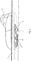
- eine perspektivische Darstellung der Anordnung der Antenne mit Antennengehäuse auf einem Fahrzeugdach im entsprechend montierten Zustand, jedoch noch ohne angeschlossene FAKRA-Verbinder;
- Fig. 2 bis 9
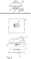
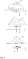
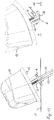
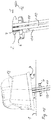
- Darstellungen der Abfolge des Positionierens der Antennenanordnung über einer Aussparung einer Befestigungsfläche mit Illustration des Montageablaufs in jeweils verschiedenen Ansichten, wobei die
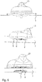
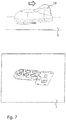
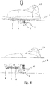
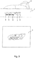
Fig. 2 den Schritt der Positionierung über dem Lochbild,Fig. 3 die Schwenkbewegung der Antenne in Richtung Befestigungsblech nebst Eintauchen,Fig. 4 das seitliche Schieben der Klemmplatte durch das Lochbild,Fig. 5 das Bewegen der Klemmplatte auf der gegenüberliegenden Seite der Aussparung,Fig. 6 das vollständige Eintauchen der Antenne in die Aussparung,Fig. 7 das Vorverrasten der Antennenanordnung,Fig. 8 das exakte Positionieren des Fehlsteckschutzes undFig. 9 das letztendliche Verschrauben der Klemmplatte mit der Antenne illustriert; - Fig. 10a) und b)
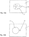
- verschiedene Lochbilder mit einem Lochbild für Montage nach
Fig. 2 ) und für eine Nachrüstung bzw. die zweite Ausführungsform der Erfindung (Fig. 10b ); - Fig. 11a) bis c)
- eine Darstellung eines alternativen Lochbilds bzw. in einer alternativen Aussparung in Form eines Langlochs mit Taillierung für eine in den
Fig. 11 b) und c) gezeigte Ausgestaltung der erfindungsgemäßen Vorrichtung mit der Weiterbildung der Bodenplatte mit zwei benachbarten Teilbereichen des ersten Bereichs, wobei im Abstandsraum der zweite Bereich mit Klemmplatte realisiert ist und - Fig. 12 bis 16
- einen Montageablauf gemäß der zweiten Ausführungsform.
- Die in den Ausführungsbeispielen gezeigte Antennenanordnung geht von einer Befestigungsfläche 1, insbesondere einem Fahrzeugdach aus. Die Befestigungsfläche 1 weist eine Aussparung 2 für Antennenanschlussmittel 10 auf.
- Im gezeigten Beispiel finden in der Aussparung 2 sechs FAKRA-Stecker Bauraum.
- Ausgehend vom Antennenfuß bzw. einer Bodenplatte 3 sind Elemente zum Fehlsteckschutz und zur Vorverrastung in an sich bekannter Weise ausgeführt.
- In einem Bereich, der von demjenigen der Antennenanschlussmittel 10 lateral entfernt ist, befindet sich eine Klemmplatte 6 mit Schraube oder Schraubbolzen 7. Über die Schraube oder den Schraubbolzen 7 ist die Klemmplatte 6 in Richtung Bodenplatte 3, d.h.in Richtung Antennengehäuse, beweg- und verspannbar, um die Antennenanordnung klemmend auf der Fläche 1 zu fixieren.
- In einer bevorzugten Lösung gemäß den
Fig. 1 bis 10a ) ist die Breite B der Aussparung 2 kleiner als die Breite der Klemmplatte 6. Die Länge L der Aussparung 2 ist hingegen größer als die Länge der Klemmplatte 6, und zwar derart, dass ein einschwenkendes Eintauchen der Verbindungsmittel mit Klemmplatte 6 in die Aussparung 2 möglich ist, wobei bei erreichter, positionsgerechter Befestigungsendlage die Gruppe von Steckern oder Buchsen 10 der Antennenanschlussmittel innerhalb der Aussparung 2 befindlich und frei zugänglich ist, wie dies insbesondere dieFig. 1 und dieFig. 9 zeigen. - Der Vorgang des Einschwenkens mit Verschieben und Befestigen soll anhand der
Fig. 2 bis 9 erläutert werden. - Die Antennenanordnung wird gemäß
Fig. 2 über dem Lochbild, d.h. über der Aussparung 2 positioniert. Im nächsten Schritt erfolgt gemäßFig. 3 ein Einschwenken mit Eintauchen eines ersten Klemmplattenendes in die Aussparung 2. Im Anschluss darin wird gemäßFig. 4 die Klemmplatte im angekippten oder angewinkelten Zustand seitlich durch die Aussparung 2 geschoben. Danach wird die Klemmplatte auf der bezogen auf dieFig. 4 gegenüberliegenden Seite (sieheFig. 5 ) durch die Aussparung, d.h. durch das Lochbild geführt. - Nunmehr ist gemäß
Fig. 6 die Klemmplatte 2, die größer als die Aussparung mit entsprechendem Lochbild ist, komplett unterhalb der Fläche 1 befindlich. Es wird dann ein Verschieben der Antennenanordnung in Richtung Längsachse der Aussparung vorgenommen, und zwar so lange, bis die Endlage mit Blick auf die an der Aussparung 2 anschließenden Öffnung 12, die quasi einen Fortsatz der Aussparung darstellt, erreicht ist. - Durch Bewegung der Antennenanordnung in Richtung Fläche 1 ergibt sich eine Vorverrastung und erste Fixierung.
- Nunmehr kann die Schraube oder der Schraubbolzen 7 betätigt werden, und zwar so lange, bis die Klemmplatte 6 in Anlage mit der Unterseite der Fläche 1 gelangt, so dass sich die gewünschte Flächenpressung und damit das Befestigen der Antennenanordnung einstellt.
- Der fixierte Zustand mit angezogener Klemmplatte 6 ist in der
Fig. 9 gezeigt. - Die prinzipielle Ausführungsform der Aussparung 2 in Form eines langlochähnlichen Lochbilds ist in der
Fig. 10a ) gezeigt. Diese Form des Lochbilds findet bevorzugt Anwendung bei der Erstausrüstung bzw. der Kraftfahrzeug-herstellungsgemäßen Montage einer entsprechenden Antenne. Das Lochbild gemäßFig. 10b ) kann für Nachrüstzwecke genutzt werden. Die in diesem Fall gegebene kreisförmige Aussparung ist im Nachrüstfall durch Werkstätten oder den Laien leichter auszuführen. Mögliche Nachteile durch eine etwas längere Zeitdauer beim Einschwenken und Finden der exakten Position hinsichtlich Klemmplatte und deren Lage unterhalb der Fläche 1 können in Kauf genommen werden. - Das Lochbild gemäß
Fig. 10b ) stellt sich als kreisförmiges Lochbild 2 dar. Beabstandet vom kreisförmigen Lochbild 2 ist eine kleinere, hier beispielhaft ebenfalls kreisförmige Aussparung 12 zur Aufnahme einer Verdrehsicherungsnase, die sich von der Bodenplatte der Antennenanordnung in Richtung Befestigungsfläche erstreckt. - Der Vorgang des Montierens der Antennenanordnung gemäß der zweiten Ausführungsform der Erfindung wird später unter Rückgriff und Bezugnahme auf die
Fig. 12 bis 16 näher erläutert. - Die
Fig. 11a ) bis c) demonstriert ein weiteres Ausführungsbeispiel der Ausbildung der erfindungsgemäßen Vorrichtung, wobei ebenfalls sichergestellt ist, dass dort, wo die Klemmplatte 6 ausgeführt ist, keine Behinderung bezogen auf die Zugänglichkeit von Buchsen für Antennenanschlussmittel vorliegt. - Die Aussparung 2 gemäß
Fig. 11a ) besitzt von der Grundstruktur ebenfalls die Form eines Langlochs, allerdings mit einer Taillierung 14 quasi im mittigen Bereich. - Dort, wo die Taillierung 14 der Aussparung 2 ausgeführt ist, kommt im Montagezustand (siehe
Fig. 11b ) und c)) die Klemmplatte 6 an der Unterseite der Befestigungsfläche 1 zum Liegen. - Es weist also die Lösung gemäß den
Fig. 11a ) bis c) der erste Bereich der Bodenplatte 3 der Antennenanordnung zwei beabstandete Teilbereiche auf, wobei im Abstandsraum der zweite Bereich mit Klemmplatte 6 ausgebildet ist. - Grundsätzlich sind die Lochbilder für die serienmäßige Ausrüstung bzw. für eine Nachrüstung im After-Market-Geschäft abmessungsseitig gleich. Beim Serienfertigungseinsatz wird die gesamte Antenne eingeschwenkt mit Blick auf die erfindungsgemäßen Merkmale nach obiger Erläuterung. Beim Nachrüsten einer Antenne ist dies nicht möglich. In diesem Fall wird die Klemmplatte bzw. Mutter und Schraube demontiert und die Antenne auf die Aussparung gesetzt und dann verschraubt. Mit einer einzigen Antennenkonfiguration können insofern alle Lochbilder genutzt werden. Hinsichtlich der Serienmontage ist festzuhalten, dass ein Montieren ohne Schwenkbewegung nicht möglich ist. Die Antennenanordnung wird üblicherweise über die kürzeste Seite der Bodenplatte zum Befestigungsmittelpunkt montiert bzw. eingeschwenkt. Durch diese Lösung kann grundsätzlich die Aussparung klein und die Schraube zur Befestigung kurz gehalten werden, da diese nicht zu weit in den Fahrgastraum bei Außenmontage bzw. in das Gehäuse bei Innenmontage hineinragt. Ein positiver Nebeneffekt ist weiterhin, dass die Aufbauhöhe des Gehäuses reduziert werden kann, was zur Gewichtserleichterung und zu Materialersparnissen führt.
- Mit Hilfe der
Figuren 12 bis 16 sei der Montageablauf gemäß der zweiten Ausführungsform der Erfindung näher erläutert. - Eine Antennenanordnung 13 soll auf eine Befestigungsfläche 1, beispielsweise einem Fahrzeugdach montiert werden.
- Die Antennenanschlussmittel 10 sind hier als Kabel ausgebildet, an deren Enden sich nicht gezeigte Stecker oder Buchsen befinden.
- Gemäß
Fig. 12 werden die Kabel durch eine kreisförmige Aussparung 2 (siehe auchFig. 10b )) geführt. - Im nächsten Schritt erfolgt ein Anwinkeln der Antennenanordnung 13, wobei die Klemmplatte 6 der Anwinklung folgt. Auf diese Weise kann die Klemmplatte in die Aussparung 2 hineingeschwenkt werden (
Fig. 13 ). - Die Längsausdehnung der Klemmplatte 6 ist dabei um ein definiertes Maß größer als der Durchmesser der kreisförmigen Aussparung 2.
- Nachdem gemäß
Fig. 14 die Klemmplatte 6 mit Hilfe der Verschwenk- und Anwinkelungsbewegung komplett durch die Aussparung 2 geführt wurde, wird die gesamte Anordnung durch das Lochbild geschoben (Fig. 15 ). - Es ist aus den Figuren ersichtlich, dass durch die schmale Ausgestaltung der Klemmplatte 6 genügend Raum zwischen Klemmplatte 6 und Aussparung 2 verbleibt, um die Antennenanschlussmittel 10 aufzunehmen.
- Die Breite der Klemmplatte 6 ist also für die Montage in der Aussparung 2 mit kreisförmigem Querschnitt kleiner als der Durchmesser der Aussparung 2 gewählt.
- Ergänzend kann die Klemmplatte 6 an ihren Längsseiten dort, wo die Antennenanschlussmittel 10 anliegen, Aussparungen aufweisen, z. B. solche Aussparungen, die der Querschnittsfläche der betreffenden Anschlussmittel 10 angepasst sind. Hierdurch ergibt sich eine weitere Führung und sichere Fixierung der Anschlussmittel, so dass eine Beschädigung dieser im späteren Betrieb, z. B. bedingt durch Metallkanten im Bereich der Aussparung, ausgeschlossen sind.
- Nach dem erfolgreichen Schieben der Anordnung durch die Aussparung kommt die Bodenplatte 3 der Antennenanordnung 13 auf der Oberseite der Befestigungsfläche 1 zum Liegen.
- Ein Arretierungsfortsatz, z. B. ausgebildet als Nase 15, erstreckt sich von der Bodenplatte 3 in Richtung einer Arretierungsöffnung 12, so dass die gewünschte Verdrehsicherung gegeben ist. Wenn die Position gemäß
Fig. 16 erreicht ist, wird dann unter Nutzung des Schraubbolzens 7 die Antennenanordnung 13 verspannt. -
- 1
- Befestigungsfläche
- 2
- Aussparung
- 3
- Bodenplatte
- 6
- Klemmplatte
- 7
- Schraubbolzen
- 8
- Fortsatz
- 10
- Antennenanschlussmittel
- 12
- Öffnung
- 13
- Antennenanordnung
- 14
- Taillierung
- 15
- Nase
Claims (8)
- Vorrichtung zum positionsgerechten Befestigen einer Antennenanordnung an einer Fläche (1), welche eine Aussparung (2) für Antennenanschlussmittel, ausgebildet als Stecker oder Buchsen (10), aufweist, wobei die Antennenanordnung eine Bodenplatte (3) besitzt, von der sich Verbindungsmittel zur Aussparung (2) erstrecken, welche eine gegen Verlust gesicherte Klemmplatte (6) und eine Schraube oder einen Schraubbolzen (7) umfassen derart, dass die Klemmplatte (6) mittels Schraube oder Schraubbolzen (7) in Richtung Bodenplatte (3) beweg- und verspannbar ist,
dadurch gekennzeichnet, dass
die Breite (B) der Aussparung (2) kleiner als die Breite der Klemmplatte (6) und die Länge (L) der Aussparung (2) größer als die Länge der Klemmplatte (6) ist, derart, dass ein einschwenkendes Eintauchen der Verbindungsmittel mit Klemmplatte (6) in die Aussparung (2), ein Verschieben in Richtung der Längsachse der Aussparung (2) und ein anschließendes Verspannen realisierbar ist, wobei bei erreichter, positionsgerechter Befestigungsendlage eine Gruppe von Steckern oder Buchsen (10) der Antennenanschlussmittel innerhalb der Aussparung (2) befindlich und frei zugänglich ist. - Vorrichtung nach Anspruch 1,
dadurch gekennzeichnet, dass
die Stecker oder Buchsen (10) in einem ersten Bereich der Bodenplatte (3) und die Klemmplatte (6) mit Schraube oder Schraubbolzen (7) in einem, vom ersten lateral beabstandeten, zweiten Bereich der Bodenplatte (3) ausgebildet sind, derart, dass ein freier Zugang zu den Anschlussmitteln gegeben ist. - Vorrichtung nach Anspruch 1 oder 2,
dadurch gekennzeichnet, dass
die Aussparung (2) eine Langlochform aufweist, wobei auf der Längsachse des Langlochs die Aussparung (2) in eine sich anschließende Öffnung (12) für einen Verdrehschutz übergeht oder der Aussparung (2) eine beabstandete Öffnung (12) für einen Verdrehschutz zugeordnet ist. - Vorrichtung nach Anspruch 2 oder 3,
dadurch gekennzeichnet, dass
im ersten Bereich der Bodenplatte (3) sich in Richtung Aussparung (2) erstreckende Fortsätze (8) zur Vorverrastung und zum Fehlsteckschutz vorgesehen sind, wobei die Fortsätze (8) so ausgebildet sind, dass selbige mindestens in Teilabschnitten die Kontur des Lochbilds, insbesondere der Langlochform-Aussparung angenähert sind oder diese Kontur approximieren. - Vorrichtung nach einem der Ansprüche 2 bis 4,
dadurch gekennzeichnet, dass
der erste Bereich der Bodenplatte (3) zwei beabstandete Teilbereiche aufweist, wobei im Abstandsraum der zweite Bereich mit Klemmplatte (6) ausgebildet ist. - Vorrichtung nach Anspruch 5,
dadurch gekennzeichnet, dass
die Aussparung (2) ein Lochbild in Langlochform mit Taillierung (14) aufweist. - Vorrichtung nach Anspruch 6,
dadurch gekennzeichnet, dass
die Klemmplatte (6) im Befestigungszustand im Bereich der Taillierung positioniert ist. - Vorrichtung zum positionsgerechten Befestigen einer Antennenanordnung an einer Fläche (1), welche eine Aussparung (2) für Antennenanschlussmittel, ausgebildet als Kabel, Stecker oder Buchsen (10), aufweist, wobei die Antennenanordnung eine Bodenplatte (3) besitzt, von der sich Verbindungsmittel zur Aussparung (2) erstrecken, welche eine gegen Verlust gesicherte Klemmplatte (6) und eine Schraube oder einen Schraubbolzen (7) umfassen derart, dass die Klemmplatte (6) mittels Schraube oder Schraubbolzen (7) in Richtung Bodenplatte (3) beweg- und verspannbar ist,
dadurch gekennzeichnet, dass
die Aussparung (2) eine Kreisform aufweist, wobei die Breite der Klemmplatte (6) kleiner als der Durchmesser der Aussparung (2) und die Länge (L) der Klemmplatte (6) größer als der Durchmesser der Aussparung (2) ist, derart, dass ein einschwenkendes Eintauchen der Verbindungsmittel mit Klemmplatte (6) in die Aussparung (2), ein Verschieben entgegen der Eintauchrichtung und ein anschließendes Verspannen realisierbar ist, wobei bei erreichter, positionsgerechter Befestigungsendlage die Antennenanschlussmittel (10) innerhalb der Aussparung (2) im Abstandsraum zwischen dieser und mindestens einer der Längsseiten der Klemmplatte (6) befindlich sind.
Applications Claiming Priority (3)
| Application Number | Priority Date | Filing Date | Title |
|---|---|---|---|
| DE102016005238 | 2016-04-29 | ||
| DE102016121697 | 2016-11-11 | ||
| DE102017107534.8A DE102017107534A1 (de) | 2016-04-29 | 2017-04-07 | Vorrichtung zum positionsgerechten Befestigen einer Antennenanordnung |
Publications (2)
| Publication Number | Publication Date |
|---|---|
| EP3240104A1 true EP3240104A1 (de) | 2017-11-01 |
| EP3240104B1 EP3240104B1 (de) | 2020-09-30 |
Family
ID=58644951
Family Applications (1)
| Application Number | Title | Priority Date | Filing Date |
|---|---|---|---|
| EP17168712.2A Active EP3240104B1 (de) | 2016-04-29 | 2017-04-28 | Vorrichtung zum positionsgerechten befestigen einer antennenanordnung |
Country Status (1)
| Country | Link |
|---|---|
| EP (1) | EP3240104B1 (de) |
Cited By (1)
| Publication number | Priority date | Publication date | Assignee | Title |
|---|---|---|---|---|
| WO2021023554A1 (de) * | 2019-08-06 | 2021-02-11 | Volkswagen Aktiengesellschaft | Befestigungssystem für eine modulare antenne |
Citations (6)
| Publication number | Priority date | Publication date | Assignee | Title |
|---|---|---|---|---|
| US3138661A (en) * | 1963-02-06 | 1964-06-23 | Grashow Joseph | Automobile antenna mount structure |
| US4136986A (en) * | 1977-06-20 | 1979-01-30 | Quick-Mount Manufacturing Company, Inc. | Automobile antenna mount structure |
| DE102005044618A1 (de) | 2005-04-12 | 2006-11-02 | Hirschmann Car Communication Gmbh | Befestigung einer Dachantenne eines Fahrzeuges mit einem Klemmteil |
| US20100013733A1 (en) * | 2008-07-17 | 2010-01-21 | Patrik Skottke | Antenna unit |
| DE202013010506U1 (de) | 2013-11-11 | 2014-01-09 | Antennentechnik Abb Bad Blankenburg Gmbh | Vorrichtung zum positionsgerechten Befestigen einer Antennenanordnung an einer Fläche |
| WO2017061923A1 (en) * | 2015-10-08 | 2017-04-13 | Scania Cv Ab | Fastening device, primarily for installation of an antenna on a vehicle |
-
2017
- 2017-04-28 EP EP17168712.2A patent/EP3240104B1/de active Active
Patent Citations (6)
| Publication number | Priority date | Publication date | Assignee | Title |
|---|---|---|---|---|
| US3138661A (en) * | 1963-02-06 | 1964-06-23 | Grashow Joseph | Automobile antenna mount structure |
| US4136986A (en) * | 1977-06-20 | 1979-01-30 | Quick-Mount Manufacturing Company, Inc. | Automobile antenna mount structure |
| DE102005044618A1 (de) | 2005-04-12 | 2006-11-02 | Hirschmann Car Communication Gmbh | Befestigung einer Dachantenne eines Fahrzeuges mit einem Klemmteil |
| US20100013733A1 (en) * | 2008-07-17 | 2010-01-21 | Patrik Skottke | Antenna unit |
| DE202013010506U1 (de) | 2013-11-11 | 2014-01-09 | Antennentechnik Abb Bad Blankenburg Gmbh | Vorrichtung zum positionsgerechten Befestigen einer Antennenanordnung an einer Fläche |
| WO2017061923A1 (en) * | 2015-10-08 | 2017-04-13 | Scania Cv Ab | Fastening device, primarily for installation of an antenna on a vehicle |
Cited By (4)
| Publication number | Priority date | Publication date | Assignee | Title |
|---|---|---|---|---|
| WO2021023554A1 (de) * | 2019-08-06 | 2021-02-11 | Volkswagen Aktiengesellschaft | Befestigungssystem für eine modulare antenne |
| CN114430874A (zh) * | 2019-08-06 | 2022-05-03 | 大众汽车股份公司 | 用于模块化天线的固定系统 |
| US20220285822A1 (en) * | 2019-08-06 | 2022-09-08 | Volkswagen Aktiengesellschaft | Fastening system for a modular antenna |
| US12095137B2 (en) * | 2019-08-06 | 2024-09-17 | Volkswagen Aktiengesellschaft | Fastening system for a modular antenna |
Also Published As
| Publication number | Publication date |
|---|---|
| EP3240104B1 (de) | 2020-09-30 |
Similar Documents
| Publication | Publication Date | Title |
|---|---|---|
| EP2367235B1 (de) | Stecker zur Verbindung mit einer Buchse | |
| EP3164911B1 (de) | Steckverbinder | |
| EP3353859B1 (de) | Anschlussvorrichtung für leiter | |
| EP3091615A1 (de) | Leiteranschlussklemme | |
| EP2625701B1 (de) | Vorrichtung zur lösbaren befestigung eines stromleiters an einem stromwandlergehäuse | |
| EP3069408B1 (de) | Vorrichtung zum positionsgerechten befestigen einer antennenanordnung an einer fläche | |
| DE112016004037B4 (de) | Befestigungsvorrichtung, vorrangig zur Montage einer Antenne an einem Fahrzeug | |
| EP2019259B1 (de) | Verbindungssytem für Tragschienen von Leuchteneinsätzen eines Lichtbandes | |
| EP3016215A1 (de) | Erdungsschienenvorrichtung | |
| EP3240104B1 (de) | Vorrichtung zum positionsgerechten befestigen einer antennenanordnung | |
| DE102006043176B4 (de) | Vorrichtung zum elektrischen Verbinden von zwei Sammelschienen | |
| DE102017107534A1 (de) | Vorrichtung zum positionsgerechten Befestigen einer Antennenanordnung | |
| DE202017107461U1 (de) | Vorrichtung zum positionsgerechten Befestigen einer Antennenanordnung | |
| EP2767659B1 (de) | Höhenverstellbare Rundstangenführung | |
| DE2323612A1 (de) | Elektrisches verbindungsglied | |
| DE102023118145A1 (de) | Adapterklemme zum Anklemmen eines elektrischen Leiters an eine Sammelschiene und damit gebildete Anordnung | |
| DE102007062956B3 (de) | Montagehilfe für das Montieren von wenigstens zwei Kabelschuhen | |
| DE29505752U1 (de) | Vorrichtung zum Verbinden von Platten mittels Verschraubung | |
| DE202011000714U1 (de) | Anschlussvorrichtung | |
| WO2015193190A1 (de) | Beleuchtungsanordnung | |
| DE202007007747U1 (de) | Fahrzeugantenne | |
| DE29720678U1 (de) | Elektrisches Verbinderelement | |
| DE102007025605A1 (de) | Fahrzeugantenne | |
| DE1287174B (de) | Vorrichtung zur Befestigung eines stab- oder rohrfoermigen Laengstraegers einer Antenne an einem Standrohr | |
| EP2827453B1 (de) | Elektronikvorrichtungen-Gehäuse |
Legal Events
| Date | Code | Title | Description |
|---|---|---|---|
| PUAI | Public reference made under article 153(3) epc to a published international application that has entered the european phase |
Free format text: ORIGINAL CODE: 0009012 |
|
| STAA | Information on the status of an ep patent application or granted ep patent |
Free format text: STATUS: THE APPLICATION HAS BEEN PUBLISHED |
|
| AK | Designated contracting states |
Kind code of ref document: A1 Designated state(s): AL AT BE BG CH CY CZ DE DK EE ES FI FR GB GR HR HU IE IS IT LI LT LU LV MC MK MT NL NO PL PT RO RS SE SI SK SM TR |
|
| AX | Request for extension of the european patent |
Extension state: BA ME |
|
| STAA | Information on the status of an ep patent application or granted ep patent |
Free format text: STATUS: REQUEST FOR EXAMINATION WAS MADE |
|
| 17P | Request for examination filed |
Effective date: 20180328 |
|
| RBV | Designated contracting states (corrected) |
Designated state(s): AL AT BE BG CH CY CZ DE DK EE ES FI FR GB GR HR HU IE IS IT LI LT LU LV MC MK MT NL NO PL PT RO RS SE SI SK SM TR |
|
| RAP1 | Party data changed (applicant data changed or rights of an application transferred) |
Owner name: ANTENNENTECHNIK BAD BLANKENBURG GMBH |
|
| GRAP | Despatch of communication of intention to grant a patent |
Free format text: ORIGINAL CODE: EPIDOSNIGR1 |
|
| STAA | Information on the status of an ep patent application or granted ep patent |
Free format text: STATUS: GRANT OF PATENT IS INTENDED |
|
| INTG | Intention to grant announced |
Effective date: 20200422 |
|
| GRAS | Grant fee paid |
Free format text: ORIGINAL CODE: EPIDOSNIGR3 |
|
| GRAA | (expected) grant |
Free format text: ORIGINAL CODE: 0009210 |
|
| STAA | Information on the status of an ep patent application or granted ep patent |
Free format text: STATUS: THE PATENT HAS BEEN GRANTED |
|
| AK | Designated contracting states |
Kind code of ref document: B1 Designated state(s): AL AT BE BG CH CY CZ DE DK EE ES FI FR GB GR HR HU IE IS IT LI LT LU LV MC MK MT NL NO PL PT RO RS SE SI SK SM TR |
|
| REG | Reference to a national code |
Ref country code: CH Ref legal event code: EP Ref country code: GB Ref legal event code: FG4D Free format text: NOT ENGLISH |
|
| REG | Reference to a national code |
Ref country code: DE Ref legal event code: R096 Ref document number: 502017007467 Country of ref document: DE Ref country code: AT Ref legal event code: REF Ref document number: 1319739 Country of ref document: AT Kind code of ref document: T Effective date: 20201015 |
|
| REG | Reference to a national code |
Ref country code: IE Ref legal event code: FG4D Free format text: LANGUAGE OF EP DOCUMENT: GERMAN |
|
| PG25 | Lapsed in a contracting state [announced via postgrant information from national office to epo] |
Ref country code: FI Free format text: LAPSE BECAUSE OF FAILURE TO SUBMIT A TRANSLATION OF THE DESCRIPTION OR TO PAY THE FEE WITHIN THE PRESCRIBED TIME-LIMIT Effective date: 20200930 Ref country code: NO Free format text: LAPSE BECAUSE OF FAILURE TO SUBMIT A TRANSLATION OF THE DESCRIPTION OR TO PAY THE FEE WITHIN THE PRESCRIBED TIME-LIMIT Effective date: 20201230 Ref country code: GR Free format text: LAPSE BECAUSE OF FAILURE TO SUBMIT A TRANSLATION OF THE DESCRIPTION OR TO PAY THE FEE WITHIN THE PRESCRIBED TIME-LIMIT Effective date: 20201231 Ref country code: HR Free format text: LAPSE BECAUSE OF FAILURE TO SUBMIT A TRANSLATION OF THE DESCRIPTION OR TO PAY THE FEE WITHIN THE PRESCRIBED TIME-LIMIT Effective date: 20200930 Ref country code: BG Free format text: LAPSE BECAUSE OF FAILURE TO SUBMIT A TRANSLATION OF THE DESCRIPTION OR TO PAY THE FEE WITHIN THE PRESCRIBED TIME-LIMIT Effective date: 20201230 |
|
| PG25 | Lapsed in a contracting state [announced via postgrant information from national office to epo] |
Ref country code: LV Free format text: LAPSE BECAUSE OF FAILURE TO SUBMIT A TRANSLATION OF THE DESCRIPTION OR TO PAY THE FEE WITHIN THE PRESCRIBED TIME-LIMIT Effective date: 20200930 Ref country code: RS Free format text: LAPSE BECAUSE OF FAILURE TO SUBMIT A TRANSLATION OF THE DESCRIPTION OR TO PAY THE FEE WITHIN THE PRESCRIBED TIME-LIMIT Effective date: 20200930 |
|
| REG | Reference to a national code |
Ref country code: LT Ref legal event code: MG4D |
|
| PG25 | Lapsed in a contracting state [announced via postgrant information from national office to epo] |
Ref country code: LT Free format text: LAPSE BECAUSE OF FAILURE TO SUBMIT A TRANSLATION OF THE DESCRIPTION OR TO PAY THE FEE WITHIN THE PRESCRIBED TIME-LIMIT Effective date: 20200930 Ref country code: CZ Free format text: LAPSE BECAUSE OF FAILURE TO SUBMIT A TRANSLATION OF THE DESCRIPTION OR TO PAY THE FEE WITHIN THE PRESCRIBED TIME-LIMIT Effective date: 20200930 Ref country code: RO Free format text: LAPSE BECAUSE OF FAILURE TO SUBMIT A TRANSLATION OF THE DESCRIPTION OR TO PAY THE FEE WITHIN THE PRESCRIBED TIME-LIMIT Effective date: 20200930 Ref country code: PT Free format text: LAPSE BECAUSE OF FAILURE TO SUBMIT A TRANSLATION OF THE DESCRIPTION OR TO PAY THE FEE WITHIN THE PRESCRIBED TIME-LIMIT Effective date: 20210201 Ref country code: EE Free format text: LAPSE BECAUSE OF FAILURE TO SUBMIT A TRANSLATION OF THE DESCRIPTION OR TO PAY THE FEE WITHIN THE PRESCRIBED TIME-LIMIT Effective date: 20200930 Ref country code: SM Free format text: LAPSE BECAUSE OF FAILURE TO SUBMIT A TRANSLATION OF THE DESCRIPTION OR TO PAY THE FEE WITHIN THE PRESCRIBED TIME-LIMIT Effective date: 20200930 |
|
| PG25 | Lapsed in a contracting state [announced via postgrant information from national office to epo] |
Ref country code: AL Free format text: LAPSE BECAUSE OF FAILURE TO SUBMIT A TRANSLATION OF THE DESCRIPTION OR TO PAY THE FEE WITHIN THE PRESCRIBED TIME-LIMIT Effective date: 20200930 Ref country code: ES Free format text: LAPSE BECAUSE OF FAILURE TO SUBMIT A TRANSLATION OF THE DESCRIPTION OR TO PAY THE FEE WITHIN THE PRESCRIBED TIME-LIMIT Effective date: 20200930 Ref country code: IS Free format text: LAPSE BECAUSE OF FAILURE TO SUBMIT A TRANSLATION OF THE DESCRIPTION OR TO PAY THE FEE WITHIN THE PRESCRIBED TIME-LIMIT Effective date: 20210130 Ref country code: PL Free format text: LAPSE BECAUSE OF FAILURE TO SUBMIT A TRANSLATION OF THE DESCRIPTION OR TO PAY THE FEE WITHIN THE PRESCRIBED TIME-LIMIT Effective date: 20200930 |
|
| PG25 | Lapsed in a contracting state [announced via postgrant information from national office to epo] |
Ref country code: SK Free format text: LAPSE BECAUSE OF FAILURE TO SUBMIT A TRANSLATION OF THE DESCRIPTION OR TO PAY THE FEE WITHIN THE PRESCRIBED TIME-LIMIT Effective date: 20200930 |
|
| REG | Reference to a national code |
Ref country code: DE Ref legal event code: R097 Ref document number: 502017007467 Country of ref document: DE |
|
| PLBE | No opposition filed within time limit |
Free format text: ORIGINAL CODE: 0009261 |
|
| STAA | Information on the status of an ep patent application or granted ep patent |
Free format text: STATUS: NO OPPOSITION FILED WITHIN TIME LIMIT |
|
| PG25 | Lapsed in a contracting state [announced via postgrant information from national office to epo] |
Ref country code: DK Free format text: LAPSE BECAUSE OF FAILURE TO SUBMIT A TRANSLATION OF THE DESCRIPTION OR TO PAY THE FEE WITHIN THE PRESCRIBED TIME-LIMIT Effective date: 20200930 |
|
| 26N | No opposition filed |
Effective date: 20210701 |
|
| REG | Reference to a national code |
Ref country code: NL Ref legal event code: FP |
|
| PG25 | Lapsed in a contracting state [announced via postgrant information from national office to epo] |
Ref country code: IT Free format text: LAPSE BECAUSE OF FAILURE TO SUBMIT A TRANSLATION OF THE DESCRIPTION OR TO PAY THE FEE WITHIN THE PRESCRIBED TIME-LIMIT Effective date: 20200930 |
|
| PG25 | Lapsed in a contracting state [announced via postgrant information from national office to epo] |
Ref country code: SI Free format text: LAPSE BECAUSE OF FAILURE TO SUBMIT A TRANSLATION OF THE DESCRIPTION OR TO PAY THE FEE WITHIN THE PRESCRIBED TIME-LIMIT Effective date: 20200930 Ref country code: MC Free format text: LAPSE BECAUSE OF FAILURE TO SUBMIT A TRANSLATION OF THE DESCRIPTION OR TO PAY THE FEE WITHIN THE PRESCRIBED TIME-LIMIT Effective date: 20200930 |
|
| PG25 | Lapsed in a contracting state [announced via postgrant information from national office to epo] |
Ref country code: LU Free format text: LAPSE BECAUSE OF NON-PAYMENT OF DUE FEES Effective date: 20210428 |
|
| PG25 | Lapsed in a contracting state [announced via postgrant information from national office to epo] |
Ref country code: CH Free format text: LAPSE BECAUSE OF NON-PAYMENT OF DUE FEES Effective date: 20210430 Ref country code: LI Free format text: LAPSE BECAUSE OF NON-PAYMENT OF DUE FEES Effective date: 20210430 |
|
| PG25 | Lapsed in a contracting state [announced via postgrant information from national office to epo] |
Ref country code: IE Free format text: LAPSE BECAUSE OF NON-PAYMENT OF DUE FEES Effective date: 20210428 |
|
| PG25 | Lapsed in a contracting state [announced via postgrant information from national office to epo] |
Ref country code: IS Free format text: LAPSE BECAUSE OF FAILURE TO SUBMIT A TRANSLATION OF THE DESCRIPTION OR TO PAY THE FEE WITHIN THE PRESCRIBED TIME-LIMIT Effective date: 20210130 |
|
| PG25 | Lapsed in a contracting state [announced via postgrant information from national office to epo] |
Ref country code: HU Free format text: LAPSE BECAUSE OF FAILURE TO SUBMIT A TRANSLATION OF THE DESCRIPTION OR TO PAY THE FEE WITHIN THE PRESCRIBED TIME-LIMIT; INVALID AB INITIO Effective date: 20170428 |
|
| REG | Reference to a national code |
Ref country code: AT Ref legal event code: MM01 Ref document number: 1319739 Country of ref document: AT Kind code of ref document: T Effective date: 20220428 |
|
| PG25 | Lapsed in a contracting state [announced via postgrant information from national office to epo] |
Ref country code: CY Free format text: LAPSE BECAUSE OF FAILURE TO SUBMIT A TRANSLATION OF THE DESCRIPTION OR TO PAY THE FEE WITHIN THE PRESCRIBED TIME-LIMIT Effective date: 20200930 |
|
| PG25 | Lapsed in a contracting state [announced via postgrant information from national office to epo] |
Ref country code: AT Free format text: LAPSE BECAUSE OF NON-PAYMENT OF DUE FEES Effective date: 20220428 |
|
| P01 | Opt-out of the competence of the unified patent court (upc) registered |
Effective date: 20230629 |
|
| REG | Reference to a national code |
Ref country code: DE Ref legal event code: R081 Ref document number: 502017007467 Country of ref document: DE Owner name: DESAY SV AUTOMOTIVE EUROPE GMBH, DE Free format text: FORMER OWNER: ANTENNENTECHNIK BAD BLANKENBURG GMBH, 99428 WEIMAR, DE |
|
| REG | Reference to a national code |
Ref country code: NL Ref legal event code: PD Owner name: DESAY SV AUTOMOTIVE EUROPE GMBH; DE Free format text: DETAILS ASSIGNMENT: CHANGE OF OWNER(S), MERGE; FORMER OWNER NAME: ANTENNENTECHNIK BAD BLANKENBURG GMBH Effective date: 20231106 |
|
| REG | Reference to a national code |
Ref country code: GB Ref legal event code: 732E Free format text: REGISTERED BETWEEN 20231116 AND 20231122 |
|
| REG | Reference to a national code |
Ref country code: BE Ref legal event code: PD Owner name: ANTEBB HOLDING GMBH; DE Free format text: DETAILS ASSIGNMENT: CHANGE OF OWNER(S), MERGE; FORMER OWNER NAME: ANTEBB HOLDING GMBH Effective date: 20231106 |
|
| PG25 | Lapsed in a contracting state [announced via postgrant information from national office to epo] |
Ref country code: MK Free format text: LAPSE BECAUSE OF FAILURE TO SUBMIT A TRANSLATION OF THE DESCRIPTION OR TO PAY THE FEE WITHIN THE PRESCRIBED TIME-LIMIT Effective date: 20200930 |
|
| PG25 | Lapsed in a contracting state [announced via postgrant information from national office to epo] |
Ref country code: TR Free format text: LAPSE BECAUSE OF FAILURE TO SUBMIT A TRANSLATION OF THE DESCRIPTION OR TO PAY THE FEE WITHIN THE PRESCRIBED TIME-LIMIT Effective date: 20200930 |
|
| PG25 | Lapsed in a contracting state [announced via postgrant information from national office to epo] |
Ref country code: MT Free format text: LAPSE BECAUSE OF FAILURE TO SUBMIT A TRANSLATION OF THE DESCRIPTION OR TO PAY THE FEE WITHIN THE PRESCRIBED TIME-LIMIT Effective date: 20200930 |
|
| PGFP | Annual fee paid to national office [announced via postgrant information from national office to epo] |
Ref country code: SE Payment date: 20250228 Year of fee payment: 9 |
|
| PGFP | Annual fee paid to national office [announced via postgrant information from national office to epo] |
Ref country code: NL Payment date: 20250424 Year of fee payment: 9 |
|
| PGFP | Annual fee paid to national office [announced via postgrant information from national office to epo] |
Ref country code: DE Payment date: 20250430 Year of fee payment: 9 |
|
| PGFP | Annual fee paid to national office [announced via postgrant information from national office to epo] |
Ref country code: GB Payment date: 20250422 Year of fee payment: 9 |
|
| PGFP | Annual fee paid to national office [announced via postgrant information from national office to epo] |
Ref country code: BE Payment date: 20250424 Year of fee payment: 9 |
|
| PGFP | Annual fee paid to national office [announced via postgrant information from national office to epo] |
Ref country code: FR Payment date: 20250424 Year of fee payment: 9 |