EP3240131A1 - Schutzvorrichtung für stromversorgung, stromversorgungsvorrichtung und schalterfehlerdiagnoseverfahren - Google Patents
Schutzvorrichtung für stromversorgung, stromversorgungsvorrichtung und schalterfehlerdiagnoseverfahren Download PDFInfo
- Publication number
- EP3240131A1 EP3240131A1 EP15872292.6A EP15872292A EP3240131A1 EP 3240131 A1 EP3240131 A1 EP 3240131A1 EP 15872292 A EP15872292 A EP 15872292A EP 3240131 A1 EP3240131 A1 EP 3240131A1
- Authority
- EP
- European Patent Office
- Prior art keywords
- switch
- voltage
- failure
- open
- power supply
- Prior art date
- Legal status (The legal status is an assumption and is not a legal conclusion. Google has not performed a legal analysis and makes no representation as to the accuracy of the status listed.)
- Granted
Links
Images


Classifications
-
- H—ELECTRICITY
- H01—ELECTRIC ELEMENTS
- H01M—PROCESSES OR MEANS, e.g. BATTERIES, FOR THE DIRECT CONVERSION OF CHEMICAL ENERGY INTO ELECTRICAL ENERGY
- H01M10/00—Secondary cells; Manufacture thereof
- H01M10/42—Methods or arrangements for servicing or maintenance of secondary cells or secondary half-cells
- H01M10/425—Structural combination with electronic components, e.g. electronic circuits integrated to the outside of the casing
-
- G—PHYSICS
- G01—MEASURING; TESTING
- G01R—MEASURING ELECTRIC VARIABLES; MEASURING MAGNETIC VARIABLES
- G01R19/00—Arrangements for measuring currents or voltages or for indicating presence or sign thereof
- G01R19/165—Indicating that current or voltage is either above or below a predetermined value or within or outside a predetermined range of values
-
- G—PHYSICS
- G01—MEASURING; TESTING
- G01R—MEASURING ELECTRIC VARIABLES; MEASURING MAGNETIC VARIABLES
- G01R31/00—Arrangements for testing electric properties; Arrangements for locating electric faults; Arrangements for electrical testing characterised by what is being tested not provided for elsewhere
- G01R31/26—Testing of individual semiconductor devices
- G01R31/2607—Circuits therefor
-
- H—ELECTRICITY
- H01—ELECTRIC ELEMENTS
- H01M—PROCESSES OR MEANS, e.g. BATTERIES, FOR THE DIRECT CONVERSION OF CHEMICAL ENERGY INTO ELECTRICAL ENERGY
- H01M10/00—Secondary cells; Manufacture thereof
- H01M10/42—Methods or arrangements for servicing or maintenance of secondary cells or secondary half-cells
- H01M10/48—Accumulators combined with arrangements for measuring, testing or indicating the condition of cells, e.g. the level or density of the electrolyte
-
- H—ELECTRICITY
- H02—GENERATION; CONVERSION OR DISTRIBUTION OF ELECTRIC POWER
- H02H—EMERGENCY PROTECTIVE CIRCUIT ARRANGEMENTS
- H02H1/00—Details of emergency protective circuit arrangements
- H02H1/0007—Details of emergency protective circuit arrangements concerning the detecting means
-
- H—ELECTRICITY
- H02—GENERATION; CONVERSION OR DISTRIBUTION OF ELECTRIC POWER
- H02H—EMERGENCY PROTECTIVE CIRCUIT ARRANGEMENTS
- H02H7/00—Emergency protective circuit arrangements specially adapted for specific types of electric machines or apparatus or for sectionalised protection of cable or line systems, and effecting automatic switching in the event of an undesired change from normal working conditions
- H02H7/18—Emergency protective circuit arrangements specially adapted for specific types of electric machines or apparatus or for sectionalised protection of cable or line systems, and effecting automatic switching in the event of an undesired change from normal working conditions for batteries; for accumulators
-
- H—ELECTRICITY
- H02—GENERATION; CONVERSION OR DISTRIBUTION OF ELECTRIC POWER
- H02H—EMERGENCY PROTECTIVE CIRCUIT ARRANGEMENTS
- H02H7/00—Emergency protective circuit arrangements specially adapted for specific types of electric machines or apparatus or for sectionalised protection of cable or line systems, and effecting automatic switching in the event of an undesired change from normal working conditions
- H02H7/20—Emergency protective circuit arrangements specially adapted for specific types of electric machines or apparatus or for sectionalised protection of cable or line systems, and effecting automatic switching in the event of an undesired change from normal working conditions for electronic equipment
-
- H—ELECTRICITY
- H02—GENERATION; CONVERSION OR DISTRIBUTION OF ELECTRIC POWER
- H02J—ELECTRIC POWER NETWORKS; CIRCUIT ARRANGEMENTS OR SYSTEMS FOR SUPPLYING OR DISTRIBUTING ELECTRIC POWER; SYSTEMS FOR STORING ELECTRIC ENERGY
- H02J7/00—Circuit arrangements for charging or discharging batteries or for supplying loads from batteries
- H02J7/60—Circuit arrangements for charging or discharging batteries or for supplying loads from batteries including safety or protection arrangements
- H02J7/663—Circuit arrangements for charging or discharging batteries or for supplying loads from batteries including safety or protection arrangements using battery or load disconnect circuits
-
- G—PHYSICS
- G01—MEASURING; TESTING
- G01R—MEASURING ELECTRIC VARIABLES; MEASURING MAGNETIC VARIABLES
- G01R31/00—Arrangements for testing electric properties; Arrangements for locating electric faults; Arrangements for electrical testing characterised by what is being tested not provided for elsewhere
- G01R31/327—Testing of circuit interrupters, switches or circuit-breakers
- G01R31/3277—Testing of circuit interrupters, switches or circuit-breakers of low voltage devices, e.g. domestic or industrial devices, such as motor protections, relays, rotation switches
-
- H—ELECTRICITY
- H01—ELECTRIC ELEMENTS
- H01M—PROCESSES OR MEANS, e.g. BATTERIES, FOR THE DIRECT CONVERSION OF CHEMICAL ENERGY INTO ELECTRICAL ENERGY
- H01M2200/00—Safety devices for primary or secondary batteries
-
- H—ELECTRICITY
- H01—ELECTRIC ELEMENTS
- H01M—PROCESSES OR MEANS, e.g. BATTERIES, FOR THE DIRECT CONVERSION OF CHEMICAL ENERGY INTO ELECTRICAL ENERGY
- H01M2220/00—Batteries for particular applications
- H01M2220/20—Batteries in motive systems, e.g. vehicle, ship, plane
-
- H—ELECTRICITY
- H01—ELECTRIC ELEMENTS
- H01M—PROCESSES OR MEANS, e.g. BATTERIES, FOR THE DIRECT CONVERSION OF CHEMICAL ENERGY INTO ELECTRICAL ENERGY
- H01M50/00—Constructional details or processes of manufacture of the non-active parts of electrochemical cells other than fuel cells, e.g. hybrid cells
- H01M50/50—Current conducting connections for cells or batteries
- H01M50/572—Means for preventing undesired use or discharge
- H01M50/574—Devices or arrangements for the interruption of current
-
- Y—GENERAL TAGGING OF NEW TECHNOLOGICAL DEVELOPMENTS; GENERAL TAGGING OF CROSS-SECTIONAL TECHNOLOGIES SPANNING OVER SEVERAL SECTIONS OF THE IPC; TECHNICAL SUBJECTS COVERED BY FORMER USPC CROSS-REFERENCE ART COLLECTIONS [XRACs] AND DIGESTS
- Y02—TECHNOLOGIES OR APPLICATIONS FOR MITIGATION OR ADAPTATION AGAINST CLIMATE CHANGE
- Y02E—REDUCTION OF GREENHOUSE GAS [GHG] EMISSIONS, RELATED TO ENERGY GENERATION, TRANSMISSION OR DISTRIBUTION
- Y02E60/00—Enabling technologies; Technologies with a potential or indirect contribution to GHG emissions mitigation
- Y02E60/10—Energy storage using batteries
Definitions
- a technique disclosed in the present specification relates to a power supply protective device.
- Power supply protective devices have been conventionally proposed which have a plurality of switches connected in parallel between a battery and a load, and determine presence/absence of a failure of any of the plurality of switches (see Patent Documents 1 and 2).
- a technique for diagnosing a failure of a switch is required.
- the present specification discloses a technique for diagnosing a failure of a switch by using means different from that of a conventional technique.
- a secondary battery management device includes a first switch provided between a first terminal to which at least one of a load and a charger is connected and a second terminal to which a power supply is connected; a switching circuit connected in parallel to the first switch and including a second switch and a voltage drop element connected in series to the second switch and causing a voltage drop of a reference voltage by a current flow; a voltage detection unit which detects at least one voltage of a first voltage as a voltage of the first terminal, a second voltage as a voltage of the second terminal, and a third voltage as a voltage at a point between the second switch and the voltage drop element; and a control unit which gives, to the first switch and the second switch, an open instruction to bring the switch into an open state and a close instruction to bring the switch into a closed state to control switching, and obtains a voltage from the voltage detection unit.
- the control unit (1) when obtaining an open voltage in a case where the second switch is brought into the closed state and the first switch is brought into the open state during discharging of the power supply, and obtaining a close voltage in a case where the second switch is brought into the closed state and the first switch is brought into the closed state during discharging of the power supply, diagnoses the first switch as having a failure or not on the basis of the open voltage and the close voltage.
- the control unit (2) when executing first instruction processing of giving the close instruction to the first switch and the second switch, if a voltage difference between the first voltage and the second voltage detected by the voltage detection unit during execution of the first instruction processing is less than a first threshold voltage, determines that the first switch has no open failure, and/or when the third voltage detected by the voltage detection unit during execution of the first instruction processing is not less than a second threshold voltage, determines that the second switch has no open failure.
- the technique disclosed in the present specification can be realized in various forms and can be realized, for example, in various modes such as a switch failure diagnosing method of a power supply protective device, a computer program for realizing functions of a power supply protective device or a switch failure diagnosing method, a recording medium which records the computer program, and the like.
- a power supply protective device gives a close instruction to the first switch to bring the same into a closed (close) state and gives an open instruction to the second switch to bring the same into an open (opened) state and, when a voltage across the first switch is then larger than a predetermined threshold voltage, diagnoses the first switch as having a failure that the switch fails to enter the closed state even being given the close instruction and remains in the open state (hereinafter, referred to as an "open failure").
- a close instruction is given to the first switch and an open instruction is given to the second switch to diagnose an open failure of the first switch. Therefore, when the first switch has an open failure and the second switch has no failure, in other words, when the first switch is in the open state against the close instruction and the second switch is in the open state according to the open instruction, there occurs a problem that a current path between a power supply and a load is cut off to cut off output of a power supply to the load (hereinafter, referred to as "power fail").
- a battery pack 1100 is mounted on, for example, an electric vehicle or a hybrid vehicle (hereinafter, referred to as a vehicle) to supply power to a load 1500 of each of various apparatuses in the vehicle.
- the battery pack 1100 includes a secondary battery 1200 and a battery protective device 1300.
- the battery pack 1100 is one example of a power supply device.
- the secondary battery 1200 is one example of a power supply.
- the power supply may be a primary battery, a capacitor or the like, and a kind of battery is not limited.
- the secondary battery 1200 is, for example, a lithium ion battery and is a battery pack in which four cells 1210 are connected in series.
- a positive electrode side of the secondary battery 1200 is connected to the battery protective device 1300 and a negative electrode side of the secondary battery 1200 is grounded via a ground point T13.
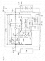
- the battery protective device 1300 includes connection terminals T11 and T12, a resistance element R, a first switch 1310, a switching circuit 1320, and a battery monitoring unit 1330.
- the connection terminal T11 is connected to the load 1500 via a wire 1510
- the connection terminal T12 is connected to the positive electrode side of the secondary battery 1200 via the wire 1510.
- the load 1500 includes, for example, an electric power steering, an accessary, and the like.
- the resistance element R is connected between the negative electrode side of the secondary battery 1200 and the ground point T13 via the wire 1510.
- the connection terminal T11 is one example of a first terminal and the connection terminal T12 is one example of a second terminal.
- the first switch 1310 is, for example, a contact relay (mechanical switch) and is connected between the connection terminal T11 and the connection terminal T12. In other words, the first switch 1310 is provided between the load 1500 and the secondary battery 1200.
- the first switch 1310 includes a magnetic coil, a point of contact, and a power transistor not shown.
- the power transistor not shown receives an open command signal from a central processing unit (hereinafter, referred to as a CPU) 1400 to be described later, the power transistor stops current supply to the magnetic coil, so that as a result, due to an electromagnetic effect, the point of contact of the first switch 1310 is mechanically opened (referred to also as "open state").
- the power transistor when the power transistor receives a close command signal from the CPU 1400, the power transistor starts current supply to the magnetic coil, so that as a result, due to an electromagnetic effect, the point of contact of the first switch 1310 is mechanically closed (referred to also as "closed state"). Having the first switch 1310 enter the closed state enables power supply to both a load driven during travelling of a vehicle such as, for example, an electric power steering and a load constantly driven such as an accessory.
- the first switch 1310 is used for supplying power to the load 1500.
- the switching circuit 1320 is connected in parallel to the first switch 1310 between the connection terminal T11 and the connection terminal T12.
- the switching circuit 1320 has a second switch and a diode D.
- the second switch and the diode D are connected in series between the connection terminal T11 and the connection terminal T12.
- the diode D is one example of a voltage drop element.
- a second switch 1340 is, for example, a field effect transistor. Upon receiving the open command signal, i.e. a gate off signal, from the CPU 1400, the second switch 1340 enters the open state. Additionally, upon receiving the close command signal, i.e. a gate on signal, from the CPU 1400, the second switch 1340 enters the closed state.
- the open command signal i.e. a gate off signal
- the close command signal i.e. a gate on signal
- the second switch 1340 is limited in an amount of current flow as compared with the first switch 1310. Therefore, even when the second switch 1340 enters the closed state, no power can be supplied to a load driven during travelling of a vehicle such as, for example, an electric power steering. In other words, the second switch 1340 is not used for supplying power to the load 1500 but used for diagnosing a failure of the first switch 1310 as will be described later.
- having the second switch 1340 enter the closed state enables power supply only to a load constantly driven such as an accessory.
- a load constantly driven such as an accessory.
- power can be supplied to a constantly driven load to form a current path between the connection terminal T11 and the connection terminal T12.
- the diode D is connected to the side of the connection terminal T11 of the switching circuit 1320, i.e. to the load side.
- the diode D is arranged to be directed from the side of the connection terminal T12 to the side of the connection terminal T11, i.e. directed such that a current direction DR from the side of the secondary battery 1200 to the side of the load 1500 is a forward direction. Therefore, a current flowing through the diode D generates a voltage drop of a forward direction voltage VF across the diode D.
- the forward direction voltage VF is one example of a reference voltage and has a fixed value. Additionally, the forward direction voltage VF is one example of a threshold voltage (a third threshold voltage or a fourth threshold voltage).
- the battery monitoring unit 1330 includes a voltage detection circuit 1350, a current detection circuit 1370, and a control unit 1360.
- the voltage detection circuit 1350 Upon receiving a detection command signal from the CPU 1400, the voltage detection circuit 1350 outputs a voltage detection signal according to a voltage between the connection terminal T11 and a ground voltage to the CPU 1400. This voltage is equal to a voltage at a terminal on the load 1500 side of the first switch 1310 and is hereinafter referred to as a load side voltage VA.
- the voltage detection circuit 1350 is one example of a voltage detection unit
- the current detection circuit 1370 is one example of a current detection unit.
- the load side voltage VA is one example of a first terminal voltage.
- the voltage detection circuit 1350 fails to have a configuration for detecting a voltage between the connection terminal T12 and the ground voltage, i.e. a power supply side voltage VB as a voltage at a terminal on the secondary battery 1200 side of the first switch 1310. Therefore, the voltage detection circuit 1350 fails to calculate a voltage ⁇ VAB across the first switch 1310 by subtracting the load side voltage VA from the power supply side voltage VB.
- the power supply side voltage VB is one example of a second terminal voltage and is larger than the forward direction voltage VF. Additionally, the power supply side voltage VB is one example of a second threshold voltage (a fifth threshold voltage).
- the current detection circuit 1370 detects a charge current or a discharge current (hereinafter, referred to as a charge/discharge current) of the secondary battery 1200 in each predetermined period. Specifically, the current detection circuit 1370 detects a current value flowing through a resistance element R to output a current detection signal according to the detected current value of the charge/discharge current to the CPU 1400.
- the control unit 1360 has the CPU 1400 and a memory 1410.
- the memory 1410 is configured with, for example, a RAM or a ROM, in which various programs are stored.
- the CPU 1400 controls each unit of the battery monitoring unit 1330 according to a program read from the memory 1410. For example, the CPU 1400 transmits the open command signal and the close command signal to the first switch 1310 and the second switch 1340 to control switching of the first switch 1310 and the second switch 1340. Additionally, the CPU 1400 transmits the detection instruction signal to the voltage detection circuit 1350 to obtain the voltage detection signal output from the voltage detection circuit 1350.
- the CPU 1400 executes switch failure diagnosing processing to be described later using the voltage detection signal obtained from the voltage detection circuit 1350.
- the switch failure diagnosing processing of the present embodiment is premised on that the second switch 1340 is normal. This is because the second switch 1340 is not used for supplying power to the load 1500 and is highly unlikely to develop a switch failure as compared with the first switch 1310.
- the switch failure diagnosing processing is executed at a time, during discharging from the secondary battery 1200 to the load 1500, after a lapse of a reference time after, for example, execution of the previous switch failure diagnosing processing, when a current value of the charge/discharge current detected by the current detection circuit 1370 becomes less than a defined discharge current value set in advance.
- a switch failure includes an open failure and a closed failure.
- the open failure is a failure in which even receiving the close command signal, the first switch 1310 remains in the open state due, for example, to a failure of a coil which drives the first switch 1310, or the like.
- the closed failure is a failure in which even receiving the open command signal, the first switch 1310 remains in the closed state due to, for example, welding of the point of contact of the first switch 1310 or the like.
- the first switch 1310 is diagnosed as having a switch failure or not and when the first switch 1310 is diagnosed as having a switch failure, the developed switch failure is diagnosed as being either an open failure or a closed failure.
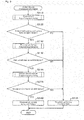
- the CPU 1400 transmits the close command signal to the second switch 1340 (S1100), and transmits the open command signal to the first switch 1310 (S1110).
- the CPU 1400 obtains an open voltage VD in a case where the first switch 1310 is in the open state and the second switch 1340 is in the closed state (S1120).
- the open voltage VD is shown as an open voltage VAD which is the open voltage VD of the load side voltage VA.
- the CPU 1400 transmits the close command signal to the first switch 1310 (S1130), and obtains a close voltage VAE in a case where both the first switch 1310 and the second switch 1340 are in the closed state
- the CPU 1400 calculates a voltage difference ⁇ V by subtracting the open voltage VAD from the close voltage VAE and compares the voltage difference ⁇ V with the forward direction voltage VF (the third threshold voltage) (S1150).
- the voltage difference ⁇ V is one example of a difference voltage.
- the CPU 1400 diagnoses the first switch 1310 as having no switch failure (S1160) to end the switch failure diagnosing processing.
- the CPU 1400 diagnoses the first switch 1310 as having a switch failure, either an open failure or a closed failure.
- the CPU 1400 further transmits the open command signal to the second switch 1340 (S1170) to obtain a discrimination voltage VG as the load side voltage VA in a case where the first switch 1310 is in the closed state and the second switch 1340 is in the open state (S1180).
- the CPU 1400 compares the obtained discrimination voltage VG with the open voltage VAD (S1190).
- the discrimination voltage VG attains zero, which is less than the open voltage VAD as a value obtained by subtracting the forward direction voltage VF from the power supply side voltage VB. Additionally, when the first switch 1310 has a closed failure, the discrimination voltage VG becomes equal to the power supply side voltage VB and becomes equal also to the open voltage VAD. When the discrimination voltage VG is not less than the open voltage VAD (S1190: YES), the CPU 1400 diagnoses the first switch 1310 as having a closed failure (S1200) to end the switch failure diagnosing processing.
- the CPU 1400 diagnoses the first switch 1310 as having an open failure (S1210) to end the switch failure diagnosing processing.
- the second switch 1340 is controlled to be in the closed state to obtain the open voltage VAD and the close voltage VAE. Therefore, during discharging from the secondary battery 1200 to the load 1500, cutoff of a current path between the secondary battery 1200 and the load 1500 can be suppressed.
- a switch failure of the first switch 1310 can be diagnosed without making a large current flow to the first switch 1310 and the second switch 1340. Therefore, even when a current value of the charge/discharge current from the secondary battery 1200 is less than the defined discharge current value, a switch failure of the first switch 1310 can be diagnosed.
- the diode D causes the forward direction voltage VF in the forward direction when current flows, a voltage difference can be easily generated. Additionally, since the diode D is arranged such that a direction from the side of the secondary battery 1200 to the side of the load 1500 is the forward direction, when a charger is connected in place of the load 1500, charging of the secondary battery 1200 via the second switch 1340 is prevented.
- the switching circuit 1320 can be configured using such a small current switch as a field-effect transistor.
- the voltage detection circuit 1350 detects only the load side voltage VA, and neither detects the power supply side voltage VB nor calculates the end-to-end voltage ⁇ VAB. Therefore, as compared with a case where the power supply side voltage VB is detected to calculate the end-to-end voltage ⁇ VAB, the configuration of the voltage detection circuit 1350 can be simplified, and the processing of the CPU 1400 in the switch failure diagnosing processing can be simplified.
- the first switch 1310 can be diagnosed as having either one of an open failure and a closed failure.
- the first switch 1310 when the first switch 1310 is diagnosed as having either one of an open failure and a closed failure, by comparing, with the open voltage VAD, the discrimination voltage VG in a case where the first switch 1310 is controlled to be in the closed state and the second switch 1340 is controlled to be in the open state, a kind of a failure developed in the first switch 1310 can be diagnosed.
- FIG. 4 to Fig. 6 Other embodiment is shown in Fig. 4 to Fig. 6 .
- the voltage detection circuit 1350 is configured to detect both the load side voltage VA and the power supply side voltage VB, and the CPU 1400 executes the switch failure diagnosing processing using the end-to-end voltage ⁇ VAB as a difference voltage between the load side voltage VA and the power supply side voltage VB, and the remainder is the same as the embodiment shown in Fig. 1 to Fig. 3 .
- the same reference signs as those of the embodiment shown in Fig. 1 to Fig. 3 are allotted hereinafter to omit description of overlaps and to make description only of the difference.
- a specific flow of the switch failure diagnosing processing of the present embodiment will be described with reference to Fig. 5 and Fig. 6 .
- whether the first switch 1310 has an open failure and whether the switch has a closed failure are diagnosed individually.
- the CPU 1400 transmits the close command signal to the second switch 1340 (S1300) and transmits the open command signal to the first switch 1310 (S1310).
- the CPU 1400 obtains an open voltage VD in a case where the first switch 1310 is in the open state and the second switch 1340 is in the closed state (S1320).
- the CPU 1400 since the voltage detection circuit 1350 detects both the load side voltage VA and the power supply side voltage VB, the CPU 1400 obtains the load side voltage VA and the power supply side voltage VB in a case where the first switch 1310 is in the open state and the second switch 1340 is in the closed state, and obtains, as an open voltage VCD, an end-to-end voltage ⁇ VAB calculated from the obtained load side voltage VA and power supply side voltage VB.
- the CPU 1400 compares the obtained open voltage VCD and the forward direction voltage VF (the fourth threshold voltage) (S1330).
- the open voltage VCD becomes equal to the forward direction voltage VF. Additionally, when the first switch 1310 has a closed failure, the open voltage VCD attains zero. When the open voltage VCD is less than the forward direction voltage VF (S1330: NO), the CPU 1400 diagnoses the first switch 1310 as having a closed failure (S1340) to end the switch failure diagnosing processing.
- the CPU 1400 transmits the close command signal to the first switch 1310 (S1350), and obtains a close voltage VCE in a case where the first switch 1310 is in the closed state and the second switch 1340 is in the closed state (S1360).
- the CPU 1400 obtains the load side voltage VA and the power supply side voltage VB in a case where the first switch 1310 is in the closed state and the second switch 1340 is in the closed state, and obtains, as the close voltage VCE, an end-to-end voltage ⁇ VAB calculated from the obtained load side voltage VA and power supply side voltage VB.
- the CPU 1400 compares the obtained close voltage VCE with the forward direction voltage VF (the fourth threshold voltage) (S1370).
- the close voltage VCE attains zero, and when the first switch 1310 has an open failure, the close voltage VCE becomes equal to the forward direction voltage VF.
- the CPU 1400 diagnoses the first switch 1310 as having an open failure (S1380) to end the switch failure diagnosing processing.
- the CPU 1400 diagnoses the first switch 1310 as having no switch failure (S1390) to end the switch failure diagnosing processing.
- determination whether the first switch 1310 has a failure or not is made using the open voltage VCD and the close voltage VCE of the end-to-end voltage ⁇ VAB across the first switch 1310. Therefore, as compared with a case where only the load side voltage VA of the first switch 1310 is detected, the number of steps of the processing required for a diagnosis of a failure of a switch can be reduced to enable whether the first switch has a failure or not to be diagnosed with ease.
- the present embodiment enables the battery protective device 1300 to diagnose whether the first switch 1310 has an open failure or not using only the open voltage VCD detected with the second switch 1340 in the closed state. Additionally, it is possible to diagnose the first switch 1310 as having a closed failure using only the close voltage VCE detected with the second switch 1340 in the closed state.
- the battery monitoring unit 1330 is configured to have one CPU 1400, the configuration of the battery monitoring unit 1330 is not limited thereto and may be configured to include a plurality of CPUs, configured to include such a hardware circuit as an ASIC (Application Specific Integrated Circuit) or configured to include both a hardware circuit and a CPU.
- ASIC Application Specific Integrated Circuit
- the battery pack 1100 includes one battery protective device 1300, a plurality of battery protective devices 1300 may be provided. Additionally, although in the above embodiment, the secondary battery 1200 includes a plurality of cells 1210 connected in series, only one cell may be provided or a plurality of cells connected in parallel may be provided.
- a contact relay is recited as an example of the first switch 1310.
- the first switch 1310 is not limited thereto, but may be, for example, a semiconductor element such as a bipolar transistor or a MOSFET.
- the configuration is recited which includes a magnetic coil, a point of contact, and a power transistor as an example of the first switch 1310.
- the configuration of the first switch 1310 is not limited thereto, but may be replaced with other configuration when it is not necessary to include at least one of these components, and for example, the first switch 1310 may be configured to directly receive an open command signal or a close command signal from the CPU 1400 without including a power transistor.
- an element connected in series to the second switch 1340 is not limited thereto, but may be a resistance element having high resistivity, for example, a resistance element having a resistance value of about 1 M ⁇ .
- the example is recited in which when power is supplied from the secondary battery 1200 to the load 1500, while maintaining power supply to the load 1500, a switch failure of the first switch 1310 is diagnosed.
- a switch failure of the first switch 1310 may be diagnosed while maintaining power supply to the secondary battery 1200.
- the battery protective device 1300 has the following configuration.
- a power supply protective device includes a first switch provided between a first terminal to which at least one of a load and a charger is connected and a second terminal to which a power supply is connected; a switching circuit connected in parallel to the first switch and including a second switch and a voltage drop element connected in series to the second switch and causing a voltage drop of a reference voltage by a current flow; a voltage detection unit which detects at least a voltage of the second terminal; and a control unit which controls switching of the first switch and the second switch to obtain a voltage from the voltage detection unit, in which the control unit obtains an open voltage in a case where the second switch is brought into the closed state and the first switch is brought into the open state during charging of the power supply, obtains a close voltage in a case where the second switch is brought into the closed state and the first switch is brought into the closed state during charging of the power supply, and diagnoses the first switch as having a failure or not on the basis of the open voltage and the close voltage.
- the second switch Since in the power supply protective device, when a failure of the first switch is diagnosed, the second switch is controlled to be in the closed state to obtain an open voltage and a close voltage, cutoff of a current path between the charger and the power supply is suppressed during charging of the power supply. Additionally, the voltage drop element is connected in series to the second switch, and when the first switch has no failure, a voltage difference of the reference voltage is generated between an open voltage and a close voltage. Therefore, use of this voltage difference enables determination whether the first switch has a failure or not on the basis of the open voltage and the close voltage.
- the diode D connected in series to the second switch 1340 is arranged to have a forward direction thereof disposed reverse to the current direction DR. Additionally, along with a change on the power supply side, the load side voltage VA is read on the power supply side voltage VB and the power supply side voltage VB is read on a charger side voltage VA.
- the forward direction voltage VF and the open voltage VAD are recited as determination criteria at the time of diagnosing a switch failure of the first switch 1310.
- these voltages may be appropriately increased or decreased taking into consideration of, for example, effects of a resistance, noise and the like of the wire 1510. For example, a half value of each of these voltages may be used as a determination criterion.
- a switch failure of the first switch 1310 is diagnosed assuming that the second switch 1340 is normal.
- switch failures of the first switch 1310 and the second switch 1340 may be diagnosed.
- Switch failure diagnosing processing of diagnosing switch failures of the first switch 1310 and the second switch 1340 is approximately the same as that of other embodiment, with a difference being in determination whether a switch failure develops or not.
- the open voltage VCD attains zero.
- the second switch 1340 has a switch failure or not cannot be diagnosed.
- the open voltage VCD becomes equal to the power supply side voltage VB
- the open voltage VCD becomes equal to the forward direction voltage VF
- the close voltage VCE attains zero.
- the close voltage VCE becomes equal to the power supply side voltage VB
- the close voltage VCE becomes equal to the forward direction voltage VF.
- the CPU 1400 is allowed to diagnose the second switch 1340 as having an open failure when at least one of the open voltage VCD and the close voltage VCE is not less than the power supply side voltage VB.
- the CPU 1400 is not allowed to diagnose the second switch 1340 as being normal or the second switch 1340 as having an open failure when at least one of the open voltage VCD and the close voltage VCE is not less than the forward direction voltage VF and is less than the power supply side voltage VB.
- the above states of (4) to (7) can be diagnosed when a current path between the secondary battery 1200 and the load 1500 may be cut off during discharging from the secondary battery 1200 to the load 1500.
- Fig. 7 shows the cutoff voltage VH as an end-to-end voltage ⁇ VAB in a case where the first switch 1310 is in the open state and the second switch 1340 is in the open state.
- the CPU 1400 obtains the cutoff voltage VH at time allowed to cut off power supply to the load 1500.
- Timing allowed to cut off power supply to the load 1500 is, for example, timing when the alternator operates to supply power such as timing of travelling. In this case, even when the power supply is cut off for several seconds required for obtaining the cutoff voltage VH due to power supply from the alternator, operation is not affected.
- the cutoff voltage VH becomes not less than the power supply side voltage VB
- the cutoff voltage VH becomes equal to the forward direction voltage VF, i.e., becomes less than the power supply side voltage VB.
- comparison between the cutoff voltage VH detected with both the first switch 1310 and the second switch 1340 set to the closed state and the power supply side voltage VB enables the second switch 1340 to be diagnosed as being normal or having a closed failure, and as a result, the states of (4) to (7) can be diagnosed.
- the battery pack 2100 is mounted on, for example, an electric vehicle or a hybrid vehicle (hereinafter, referred to as a vehicle) or mounted for starting an engine (a conventional lead storage battery) of a vehicle to supply power to a load 2500 of each of various apparatuses in the vehicle.
- the battery pack 2100 includes a secondary battery 2200 and a battery protective device 2300.
- the battery pack 2100 is one example of a power supply device.
- the secondary battery 2200 is one example of a power supply and may be a primary battery or a capacitor or the like.
- the battery protective device 2300 is one example of a power supply protective device.
- Fig. 8 is a block diagram showing an entire configuration of the battery pack 2100.
- the secondary battery 2200 is, for example, a lithium ion battery, and is a battery pack including a plurality of cells 2210 (four in Fig. 8 ) connected in series.
- a positive electrode side of the secondary battery 2200 is connected to the battery protective device 2300, and a negative electrode side of the secondary battery 2200 is connected to a ground voltage via a ground point T24.
- the battery protective device 2300 includes connection terminals T21 and T22, a resistance element R1, a first switch 2310, a switching circuit 2320, a ground circuit 2330, and a battery monitoring unit 2340.
- the connection terminal T21 is connected to the load 2500 via a wire 2510
- the connection terminal T22 is connected to the positive electrode side of the secondary battery 2200 via the wire 2510.
- the load 2500 includes, for example, an electric power steering, an accessory, and the like.
- the resistance element R1 is connected between the negative electrode side of the secondary battery 2200 and the ground point T24 via the wire 2510.
- the connection terminal T21 is one example of a first terminal and similarly to T12, the connection terminal T22 is one example of a second terminal.
- first switch 2310 and a second switch 2350 are the same as the first switch 1310 and the second switch 1340 in the first embodiment, no description will be made of detailed configurations thereof.
- the diode D is connected to the connection terminal T21 side of the second switch 2350, i.e. to the load side. Since details of the diode D are the same as those of the first embodiment, no description will be made thereof.
- a forward direction voltage VF is one example of a first threshold voltage.
- the ground circuit 2330 is connected between a middle point T23 between the second switch 2350 of the switching circuit 2320 and the diode D, and the ground point T24.
- the ground circuit 2330 has a third switch 2360 and a resistance element R2.
- the third switch 2360 and the resistance element R2 are connected in series between the middle point T23 and the ground point T24.
- the middle point T23 is one example of a point between a second switch and a voltage drop element.
- the third switch 2360 is, for example, a field-effect transistor. When receiving an open instruction signal from a CPU 2400, the third switch 2360 enters an open state. Additionally, when receiving a close instruction signal from the CPU 2400, the third switch 2360 enters a closed state.
- the resistance element R2 is connected to the middle point T23 side of the third switch 2360.
- the ground circuit 2330 connects the middle point T23 to a ground voltage via the ground point T24 when the third switch 2360 enters the closed state.
- the battery monitoring unit 2340 includes a voltage detection circuit 2370, a current detection circuit 2380, and a control unit 2390 which are the same as the voltage detection circuit 1350, the current detection circuit 1370, and the control unit 1360 in the first embodiment, respectively. Thus, since the battery monitoring unit 2340 is the same as the battery monitoring unit 1330 in the first embodiment, no detailed description will be made thereof.
- a load side voltage VA is one example of a first voltage.
- the voltage detection circuit 2370 when receiving a detection instruction signal from the CPU 2400, the voltage detection circuit 2370 outputs a voltage detection signal according to a voltage between the connection terminal T22 and the ground voltage to the CPU 2400.
- This voltage is equal to a voltage of each terminal of the first switch 2310 and the second switch 2350 on the secondary battery 2200 side, and is hereinafter referred to as a power supply side voltage VB.
- the power supply side voltage VB is one example of a second voltage.
- the voltage detection circuit 2370 when receiving the detection instruction signal from the CPU 2400, the voltage detection circuit 2370 outputs the voltage detection signal according to a voltage between the middle point T23 and the ground voltage to the CPU 2400.
- This voltage is equal to a voltage of a terminal of the second switch 2350 on the load 2500 side, and is hereinafter referred to as an intermediate voltage VC.
- the intermediate voltage VC is one example of a third voltage.
- the control unit 2390 has the CPU 2400 and a memory 2410 which are the same as the CPU 1400 and the memory 1410 in the first embodiment, respectively. Thus, since the control unit 2390 is the same as the control unit 1360 in the first embodiment, no detailed description will be made thereof.
- the CPU 2400 diagnoses switch failures of the first switch 2310 and the second switch 2350.
- a switch failure includes an open failure and a closed failure.
- an open failure represents a failure in which a switch fails to enter the closed state and remains in the open state even when given a close instruction, for example, a failure of a magnetic coil which drives the first switch 2310. Therefore, an open failure of the first switch 2310 is diagnosed with the close instruction signal being transmitted to the first switch 2310.
- a closed failure represents a failure in which a switch fails to enter the open state and remains in the closed state even when given an open instruction, for example, a failure developed when a point of contact of the first switch 2310 welds. Therefore, a closed failure of the first switch 2310 is diagnosed with the open instruction signal being transmitted to the first switch 2310. This is also the case with the second switch 2350.
- the open instruction signal is transmitted to the first switch 2310, and the close instruction signal is transmitted to the second switch 2350 as well in order to suppress occurrence of a power fail.
- the close instruction signal is transmitted to the second switch 2350, if the second switch 2350 has an open failure, a power fail cannot be suppressed from occurring. Therefore, a diagnosis of a closed failure of the first switch 2310 is conducted after a diagnosis of an open failure of the second switch 2350. Similarly, a diagnosis of a closed failure of the second switch 2350 is conducted after a diagnosis of an open failure of the first switch 2310.
- Fig. 13 is a table of failure diagnoses of the first switch 2310 and the second switch 2350 according to the present embodiment. As shown in Fig. 13 , in the present embodiment, with the close instruction signal being transmitted to the first switch 2310 and the second switch 2350, open failures of the first switch 2310 and the second switch 2350 are diagnosed. In this case, there is a possibility that the following four states are realized.
- the first switch 2310 and the second switch 2350 simultaneously have an open failure.
- the Patterns 1 to 3 since at least one of the first switch 2310 and the second switch 2350 is in the closed state, a current path can be ensured between the secondary battery 2200 and the load 2500 via the above one switch. Then, use of the load side voltage VA, the power supply side voltage VB, and the intermediate voltage VC obtained from the voltage detection circuit 2370 enables determination which of the Patterns 1 to 3, the first switch 2310 and the second switch 2350 have. This enables suppression of a power fail to diagnose open failures of the first switch 2310 and the second switch 2350.
- closed failures of the first switch 2310 and the second switch 2350 are diagnosed on condition that the first switch 2310 and the second switch 2350 are diagnosed as having no open failure.
- a closed failure of the first switch 2310 is diagnosed with the open instruction signal being transmitted to the first switch 2310 and the close instruction signal being transmitted to the second switch 2350. In this case, there is a possibility that the following four states are realized.
- the switch failure diagnosing processing of the present embodiment is premised on that the third switch 2360 has no failure. This is because the third switch 2360 is not used for supplying power to the load 2500 and is highly unlikely to develop a switch failure as compared with the first switch 2310 and the second switch 2350.
- the third switch 2360 is given the close instruction signal in a period of detecting the intermediate voltage VC by the voltage detection circuit 2370 and given the open instruction signal in a period of detecting no intermediate voltage VC, the number of times of switching of the third switch between the open state and the closed state is smaller as compared with the first switch 2310 and the second switch 2350 to have an extremely low probability of having a switch failure.
- Fig. 9 is a flow chart showing the switch failure diagnosing processing executed by the CPU 2400.
- the switch failure diagnosing processing is started, at a time, during discharging from the secondary battery 2200 to the load 2500, after a lapse of a reference time after, for example, execution of the previous switch failure diagnosing processing, when a current value of the charge/discharge current detected by the current detection circuit 2380 becomes less than a defined discharge current value set in advance.
- the CPU 2400 executes open failure diagnosing processing of diagnosing open failures of the first switch 2310 and the second switch 2350 (S2110).
- Fig. 10 is a flow chart showing the open failure diagnosing processing executed by the CPU 2400.
- the open failure diagnosing processing first, determination is made whether the first switch 2310 has an open failure or not, and when the determination is made that the first switch 2310 has no open failure, determination is made whether the second switch 2350 has an open failure or not.
- the CPU 2400 transmits the close instruction signal to the first switch 2310, transmits the close instruction signal to the second switch 2350, and transmits the open instruction signal to the third switch 2360 (S2310).
- the CPU 2400 obtains the load side voltage VA and the power supply side voltage VB in a first instruction state where the close instruction signal is transmitted to the first switch 2310 and the close instruction signal is transmitted to the second switch 2350 (S2340).
- the potential difference ⁇ VAB becomes approximately zero.
- the potential difference ⁇ VAB attains the forward direction voltage VF.
- the CPU 2400 determines that the first switch 2310 has an open failure (S2360) to end the open failure diagnosing processing.
- the CPU 2400 determines that the first switch 2310 has no open failure (S2370). When determining that the first switch 2310 has no open failure, the CPU 2400 transmits the close instruction signal to the third switch 2360 (S2380) to obtain the intermediate voltage VC in the first instruction state (S2390).
- the CPU 2400 Upon completing obtaining the intermediate voltage VC in the first instruction state, the CPU 2400 transmits the open instruction signal to the third switch 2360 (S2400) to bring the third switch 2360 into the open state. Specifically, during a period of obtaining the intermediate voltage VC, the CPU 2400 transmits the close instruction signal to the third switch 2360 to bring the third switch 2360 into the closed state and during a period of obtaining no intermediate voltage VC, transmits the open instruction signal to the third switch 2360 to bring the third switch 2360 into the open state.
- the CPU 2400 compares the intermediate voltage VC obtained at S2390 and a threshold voltage VT (S2410).
- the "threshold voltage VT" is set to be a voltage lower than the power supply side voltage VB and more specifically, is set to be a voltage lower than a discharging end voltage of the secondary battery 2200 at which discharging of the secondary battery 2200 is inhibited in order to prevent the secondary battery 2200 from overdischarging.
- the threshold voltage VT is one example of the second threshold voltage.
- the intermediate voltage VC is approximately equal to the power supply side voltage VB.
- the intermediate voltage VC becomes the ground voltage because the third switch 2360 is in the closed state.
- the CPU 2400 determines that the second switch 2350 has an open failure (S2420) to end the open failure diagnosing processing.
- the CPU 2400 determines that the second switch 2350 has no open failure (S2430) to end the open failure diagnosing processing.
- the CPU 2400 determines whether an open failure is present or absent (S2120).
- the CPU 2400 determines that an open failure is present (S2120: NO). In this case, the CPU 2400 determines that at least one of the first switch 2310 and the second switch 2350 has a switch failure (S2130) to end the switch failure diagnosing processing.
- the CPU 2400 determines that no open failure develops (S2120: YES). In this case, the CPU 2400 subsequently executes first switch failure diagnosing processing of diagnosing a switch failure of the first switch 2310 (S2140).
- Fig. 11 is a flow chart showing the first switch failure diagnosing processing executed by the CPU 2400.
- the first switch failure diagnosing processing first, determination is made whether the first switch 2310 has a closed failure or not, and when the determination is made that the first switch 2310 has no closed failure, another determination is made whether the first switch 2310 has an open failure or not.
- the CPU 2400 transmits the open instruction signal to the first switch 2310 while maintaining transmission of the close instruction signal to the second switch 2350 (S2510).
- the CPU 2400 obtains the load side voltage VA and the power supply side voltage VB in a second instruction state where the open instruction signal is transmitted to the first switch 2310 and the close instruction signal is transmitted to the second switch 2350 (S2520).
- the CPU 2400 calculates a potential difference ⁇ VAB and compares the potential difference ⁇ VAB and the forward direction voltage VF (S2530).
- the potential difference ⁇ VAB becomes the forward direction voltage VF.
- the potential difference ⁇ VAB attains approximately zero.
- the CPU 2400 determines that the first switch 2310 has a closed failure (S2540) to end the first switch failure diagnosing processing.
- the CPU 2400 determines that the first switch 2310 has no closed failure (S2550). When determining that the first switch 2310 has no closed failure, the CPU 2400 transmits the close instruction signal to the first switch 2310 to return the switch to the first instruction state (S2560) and obtains the load side voltage VA and the power supply side voltage VB in the first instruction state (S2570).
- the CPU 2400 uses the load side voltage VA and the power supply side voltage VB obtained at S2570, the CPU 2400 calculates a potential difference ⁇ VAB and compares the potential difference ⁇ VAB and the forward direction voltage VF (S2580). When the potential difference ⁇ VAB is not less than the forward direction voltage VF (S2580: NO), the CPU 2400 determines that the first switch 2310 has an open failure due to the open instruction signal to the first switch 2310 at S2510 (S2590) to end the open failure diagnosing processing.
- the CPU 2400 determines that the first switch 2310 has no open failure (S2600) to end the first switch failure diagnosing processing.
- the CPU 2400 determines whether a switch failure is present or absent in the first switch 2310 (S2150). When determining that the first switch 2310 has either one of a closed failure and an open failure in the first switch failure diagnosing processing, the CPU 2400 determines that the first switch 2310 has a switch failure (S2150: NO). In this case, the CPU 2400 executes the processing from S2130 to end the switch failure diagnosing processing.
- the CPU 2400 determines that the first switch 2310 has no switch failure (S2150: YES). In this case, the CPU 2400 subsequently executes second switch failure diagnosing processing of diagnosing a switch failure of the second switch 2350 (S2160).
- Fig. 12 is a flow chart showing the second switch failure diagnosing processing executed by the CPU 2400.
- the second switch failure diagnosing processing first, determination is made whether the second switch 2350 has a closed failure or not, and when the determination is made that the second switch 2350 has no closed failure, another determination is made whether the second switch 2350 has an open failure or not.
- the CPU 2400 transmits the open instruction signal to the second switch 2350 and transmits the close instruction signal to the third switch 2360 while maintaining transmission of the close instruction signal to the first switch 2310 (S2710).
- the CPU 2400 transmits the close instruction signal to the first switch 2310 to obtain the intermediate voltage VC in a third instruction state where the open instruction signal is transmitted to the second switch 2350 (S2730).
- the CPU 2400 transmits the open instruction signal to the third switch 2360 (S2740) to bring the third switch 2360 into the open state.
- the CPU 2400 compares the intermediate voltage VC obtained at S2730 and the threshold voltage VT (S2750).
- the intermediate voltage VC becomes the ground voltage.
- the intermediate voltage VC becomes approximately equal to the power supply side voltage VB.
- the CPU 2400 determines that the second switch 2350 has a closed failure (S2760) to end the second switch failure diagnosing processing.
- the CPU 2400 determines that the second switch 2350 has no closed failure (S2760). When determining that the second switch 2350 has no closed failure, the CPU 2400 transmits the close instruction signal to the second switch 2350 to return the switch to the first instruction state and also transmits the close instruction signal to the third switch 2360 (S2780) to obtain the intermediate voltage VC in the first instruction state (S2800). Upon completing obtaining the intermediate voltage VC in the first instruction state, the CPU 2400 transmits the open instruction signal to the third switch 2360 (S2810) to bring the third switch 2360 into the open state.
- the CPU 2400 compares the intermediate voltage VC obtained at S2800 and the threshold voltage VT (S2820). When the intermediate voltage VC is less than the threshold voltage VT (S2820: NO), the CPU 2400 determines that the second switch 2350 has an open failure due to the open instruction signal transmitted to the second switch 2350 at S2710 (S2830) to end the second switch failure diagnosing processing.
- the CPU 2400 determines that the second switch 2350 has no open failure (S2840) to end the second switch failure diagnosing processing.
- the CPU 2400 determines whether a switch failure of the second switch 2350 is present or absent (S2170). When determining that the second switch 2350 has either one of a closed failure and an open failure in the second switch failure diagnosing processing, the CPU 2400 determines that the second switch 2350 has a switch failure (S2170: NO). In this case, the CPU 2400 executes the processing from S2130 to end the switch failure diagnosing processing.
- the CPU 2400 determines that the second switch 2350 has no switch failure (S2170: YES). In this case, determination is made that neither the first switch 2310 nor the second switch 2350 has a switch failure (S2180) to end the switch failure diagnosing processing.
- the open failure diagnosing processing of the switch failure diagnosing processing determination whether the first switch 2310 and the second switch 2350 have an open failure or not is made in the first instruction state where the close instruction signal is transmitted to the first switch 2310 and the close instruction signal is transmitted to the second switch 2350 (S2310). Therefore, unless the first switch 2310 and the second switch 2350 simultaneously develop an open failure, no power fail occurs. In other words, even when one switch has an open failure to be in the open state against the close instruction signal, a current path can be ensured between the secondary battery 2200 and the load 2500 via the other switch to suppress a power fail from occurring.
- determination whether the first switch 2310 has a closed failure or not in the switch failure diagnosing processing is made when the determination is made that the first switch 2310 and the second switch 2350 have no open failure (S2120: YES). Therefore, in order to determine whether the first switch 2310 has a closed failure or not in the first switch failure diagnosing processing of the switch failure diagnosing processing, even when the open instruction signal is transmitted to the first switch 2310 and the close instruction signal is transmitted to the second switch 2350 to bring into the second instruction state (S2510), the second switch 2350 is reliably in the closed state, so that a power fail can be suppressed from occurring.
- the first switch failure diagnosing processing of the switch failure diagnosing processing after giving an instruction to bring the first switch 2310 into the open state, another determination is made whether the first switch 2310 has an open failure or not (S2580). Therefore, a switch failure of the first switch 2310 developed during the switch failure diagnosing processing can be diagnosed during the switch failure diagnosing processing.
- determination whether the second switch 2350 has a closed failure or not in the switch failure diagnosing processing is made when the determination is made that the first switch 2310 and the second switch 2350 have no open failure (S2120: YES). Therefore, in order to determine whether the second switch 2350 has a closed failure or not in the second switch failure diagnosing processing of the switch failure diagnosing processing, even when the close instruction signal is transmitted to the first switch 2310 and the open instruction signal is transmitted to the second switch 2350 to bring into the third instruction state (S2710), the first switch 2310 is reliably in the closed state, so that a power fail can be suppressed from occurring.
- the second switch failure diagnosing processing of the switch failure diagnosing processing after giving an instruction to bring the second switch 2350 into the open state, another determination is made whether the second switch 2350 has an open failure or not (S2820). Therefore, a switch failure of the second switch 2350 developed during the switch failure diagnosing processing can be diagnosed during the switch failure diagnosing processing.
- the battery protective device 2300 is provided with the ground circuit 2330, in which the intermediate voltage VC becomes approximately equal to the power supply side voltage VB when the second switch 2350 enters the closed state, and becomes the ground voltage when the second switch 2350 enters the open state and the third switch 2360 enters the closed state. Therefore, obtaining the intermediate voltage VC enables determination of a state of the second switch 2350. Without the ground circuit 2330 in the battery protective device 2300, the intermediate voltage VC in a case where the second switch 2350 enters the open state becomes unstable, so that the intermediate voltage VC in a case where the second switch 2350 enters the open state might become equal to the intermediate voltage VC in a case where the second switch 2350 enters the closed state.
- Providing the ground circuit 2330 in the battery protective device 2300 enables the intermediate voltage VC to be stabilized at the ground voltage in a case where the second switch 2350 enters the open state, thereby reliably making different the intermediate voltage VC in a case where the second switch 2350 enters the open state and the intermediate voltage VC in a case where the second switch 2350 enters the closed state.
- the close instruction signal is transmitted to the third switch 2360 to bring the third switch 2360 into the closed state during a period of detecting the intermediate voltage VC by the voltage detection circuit 2370
- the open instruction signal is transmitted to the third switch 2360 to bring the third switch 2360 into the open state during a period of detecting no intermediate voltage VC by the voltage detection circuit 2370 (S2380 to S2400, S2710 to S2740, and S2780 to S2810).
- the diode D is connected in series to the second switch 2350, while the diode is not connected in series to the first switch 2310. If the diode is connected in series also to the first switch 2310, a potential difference ⁇ VAB in a case where the first switch 2310 enters the closed state and the second switch 2350 enters the closed state and a potential difference ⁇ VAB in a case where the first switch 2310 enters the open state and the second switch 2350 enters the closed state become equal to each other, so that an open failure of the first switch 2310 cannot be diagnosed in the first instruction state.
- the potential difference ⁇ VAB in a case where the first switch 2310 enters the closed state and the second switch 2350 enters the closed state and the potential difference ⁇ VAB in a case where the first switch 2310 enters the open state and the second switch 2350 enters the closed state can be varied from each other. This enables a diagnosis of an open failure of the first switch 2310 in the first instruction state.
- the diode D since the diode D generates the forward direction voltage VF in the forward direction when current flows, a voltage difference can be easily generated. Additionally, since the diode D is arranged such that the direction from the secondary battery 2200 side toward the load 2500 side is the forward direction, when a charger is connected in place of the load 2500, the secondary battery 2200 can be prevented from being charged via the second switch 2350.
- the switching circuit 2320 can be configured using such a small current switch as a field-effect transistor.
- the switch failure diagnosing processing when a current value of the charge/discharge current detected by the current detection circuit 2380 of the battery protective device 2300 becomes less than a defined discharge current value, the switch failure diagnosing processing is executed. Therefore, as compared with execution of the switch failure diagnosing processing when the discharge current value is not less than the defined discharge current value, switch failures of the first switch 2310 and the second switch 2350 can be diagnosed using a smaller potential difference ⁇ VAB or intermediate voltage VC.
- a field-effect transistor is recited as examples of the second switch 2350 and the third switch 2360.
- the second switch 2350 and the third switch 2360 are not limited thereto, but may be a contact relay.
- Designing the first switch 2310 and the second switch 2350 to be normally-off switches prevents a rush current from flowing to the load 2500 at the time of starting the battery protective device 2300. Additionally, since the third switch 2360 enters the closed state during a period of detecting the intermediate voltage VC by the voltage detection circuit 2370 and enters the open state during a period of detecting no intermediate voltage VC by the voltage detection circuit 2370, designing the third switch 2360 to be a normally-off switch facilitates control of the third switch 2360.
- the above embodiment has a configuration in which the diode D is connected in series to the second switch 2350.
- an element connected in series to the second switch 2350 is not limited thereto, but may be a resistance element having high resistivity, for example, a resistance element having a resistance value of about 1 M ⁇ .
- the above embodiment has a configuration including the ground circuit 2330 connected between the middle point T23 of the switching circuit 2320 and the ground point T24.
- the ground circuit 2330 may be connected between the middle point T23 of the switching circuit 2320 and a connection point connected to a reference voltage different from the ground voltage.
- the ground circuit 2330 may not necessarily be provided.
- the above embodiment has a configuration including the third switch 2360 in the ground circuit 2330.
- the third switch 2360 may not necessarily be provided in the ground circuit 2330.
- the forward direction voltage VF is recited as an example of a reference voltage at the time of diagnosing a switch failure of the first switch 2310.
- the reference voltage may be appropriately increased or decreased taking into consideration of, for example, effects of a resistance, noise and the like of the wire 2510.
- a half value of each of the forward direction voltage VF may be used as the reference voltage.
- the threshold voltage VT used at the time of diagnosing a switch failure of the second switch 2350 and the voltage may be appropriately selected from voltages between the power supply side voltage VB and the ground voltage.
- the above embodiment has a configuration in which the intermediate voltage VC and the threshold voltage VT are compared at the time of diagnosing a switch failure of the second switch 2350.
- timing for starting the switch failure diagnosing processing is not limited thereto, and may be, for example, at time when either one condition is satisfied, a condition that a reference time has elapsed from the time of execution of the previous switch failure diagnosing processing and a condition that a current value of the charge/discharge current detected by the current detection circuit 2380 becomes less than a defined discharge current value determined in advance.
- the example is shown in which in the open failure diagnosing processing, after determination is made whether the first switch 2310 has an open failure or not, determination is made whether the second switch 2350 has an open failure or not, the order of diagnosing open failures of the first switch 2310 and the second switch 2350 may be reversed.
- the example is shown in which in the switch failure diagnosing processing, after execution of the first switch failure diagnosing processing, the second switch failure diagnosing processing is executed, the order of diagnosing switch failures of the first switch 2310 and the second switch 2350 may be reversed.
- the example is shown in which in the switch failure diagnosing processing, after determination whether the first switch 2310 and the second switch 2350 have an open failure or not, determination is made whether the first switch 2310 and the second switch 2350 have a closed failure or not.
- the switch failure diagnosing processing is not limited thereto, but may include up to the processing of determining whether the first switch 2310 and the second switch 2350 have an open failure or not, and the processing of determining whether either one of the first switch 2310 and the second switch 2350 has a closed failure or not. Additionally, only the processing of determining whether the first switch 2310 and the second switch 2350 have an open failure or not may be executed. Further, the switch failure diagnosing processing may include up to the processing of determining whether either one of the first switch 2310 or the second switch 2350 has an open failure or not.
- the example is shown in which in the first switch failure diagnosing processing, after the determination that the first switch 2310 has no closed failure, another determination is made whether the first switch 2310 has an open failure or not.
- another determination whether the first switch 2310 has an open failure or not may not necessarily be made. This is also the case with the second switch failure diagnosing processing.
- the present invention is not limited to the above embodiments and modifications.
- the embodiments and modifications disclosed here are in all aspects for illustrative purpose only and are not to be construed limitative.
- the scope of the present invention is shown not by the above description but by the scope of claims and is construed to include means equivalent to the scope of claims and all the modifications within the scope of claims. Additionally, modes configured by arbitrarily combining components included in the above embodiments and modifications are also included in the scope of the present invention.
- the battery protective device 1300 is provided with the switching circuit 1320 including the diode D and the second switch 1340.
- the battery protective device may be configured to include an FET in place of the diode D.
- Fig. 14 is a block diagram showing a configuration of thus configured battery protective device 1300.
- Fig. 15 is a block diagram showing a configuration of thus configured battery protective device 2300. With either of the configurations shown in Fig. 14 and Fig. 15 , the same effect can be produced as those of the above embodiments.
- the above second embodiment enables the diode D to be diagnosed as having a short-circuit failure or not.
- the configuration in the above second embodiment as shown in Fig. 15 enables sensing of failures of a parasitic diode Di generated between a source and a drain of an FET and a fourth switch 2361.
- the fourth switch 2361 when the first switch 2310 is in the closed state, the second switch 2350 is in the open state, and the third switch 2360 is in the closed state, the CPU 2400 enables failures of the parasitic diode Di and the fourth switch 2361 to be sensed.
- the above described technique is applicable to determination of a failure of a current path in a configuration where a switch is provided on a current path in a DC ⁇ DC converter, a generator, a solar-power generation system, an electronic apparatus, a vehicle, a household appliance, and the like.
- the present invention enables a failure of a switch to be sensed without stopping power supply.
- the present invention can be realized in various modes, and may be realized, for example, as a method for executing a power supply protective device, a program for realizing the functions of the power supply protective device, or a circuit diagnosis device operable by the method or the program.
Landscapes
- Engineering & Computer Science (AREA)
- General Chemical & Material Sciences (AREA)
- Manufacturing & Machinery (AREA)
- Chemical & Material Sciences (AREA)
- Chemical Kinetics & Catalysis (AREA)
- Electrochemistry (AREA)
- General Physics & Mathematics (AREA)
- Physics & Mathematics (AREA)
- Power Engineering (AREA)
- Microelectronics & Electronic Packaging (AREA)
- Charge And Discharge Circuits For Batteries Or The Like (AREA)
- Protection Of Static Devices (AREA)
- Secondary Cells (AREA)
- Electric Propulsion And Braking For Vehicles (AREA)
- Emergency Protection Circuit Devices (AREA)
- Keying Circuit Devices (AREA)
Priority Applications (1)
| Application Number | Priority Date | Filing Date | Title |
|---|---|---|---|
| EP20150549.2A EP3657619B1 (de) | 2014-12-24 | 2015-12-24 | Schutzvorrichtung für stromversorgung, stromversorgungsvorrichtung und switch-fehler-diagnoseverfahren |
Applications Claiming Priority (3)
| Application Number | Priority Date | Filing Date | Title |
|---|---|---|---|
| JP2014260499 | 2014-12-24 | ||
| JP2015095493 | 2015-05-08 | ||
| PCT/JP2015/006461 WO2016103721A1 (ja) | 2014-12-24 | 2015-12-24 | 電源保護装置、電源装置及びスイッチ故障診断方法 |
Related Child Applications (2)
| Application Number | Title | Priority Date | Filing Date |
|---|---|---|---|
| EP20150549.2A Division EP3657619B1 (de) | 2014-12-24 | 2015-12-24 | Schutzvorrichtung für stromversorgung, stromversorgungsvorrichtung und switch-fehler-diagnoseverfahren |
| EP20150549.2A Division-Into EP3657619B1 (de) | 2014-12-24 | 2015-12-24 | Schutzvorrichtung für stromversorgung, stromversorgungsvorrichtung und switch-fehler-diagnoseverfahren |
Publications (3)
| Publication Number | Publication Date |
|---|---|
| EP3240131A1 true EP3240131A1 (de) | 2017-11-01 |
| EP3240131A4 EP3240131A4 (de) | 2018-08-15 |
| EP3240131B1 EP3240131B1 (de) | 2020-02-26 |
Family
ID=56149779
Family Applications (2)
| Application Number | Title | Priority Date | Filing Date |
|---|---|---|---|
| EP20150549.2A Active EP3657619B1 (de) | 2014-12-24 | 2015-12-24 | Schutzvorrichtung für stromversorgung, stromversorgungsvorrichtung und switch-fehler-diagnoseverfahren |
| EP15872292.6A Active EP3240131B1 (de) | 2014-12-24 | 2015-12-24 | Schutzvorrichtung für stromversorgung, stromversorgungsvorrichtung und schalterfehlerdiagnoseverfahren |
Family Applications Before (1)
| Application Number | Title | Priority Date | Filing Date |
|---|---|---|---|
| EP20150549.2A Active EP3657619B1 (de) | 2014-12-24 | 2015-12-24 | Schutzvorrichtung für stromversorgung, stromversorgungsvorrichtung und switch-fehler-diagnoseverfahren |
Country Status (5)
| Country | Link |
|---|---|
| US (2) | US10338141B2 (de) |
| EP (2) | EP3657619B1 (de) |
| JP (1) | JP6729390B2 (de) |
| CN (2) | CN107112744B (de) |
| WO (1) | WO2016103721A1 (de) |
Cited By (3)
| Publication number | Priority date | Publication date | Assignee | Title |
|---|---|---|---|---|
| WO2020245519A1 (fr) * | 2019-06-06 | 2020-12-10 | Psa Automobiles Sa | Systeme electrique et procede de diagnostic de connexion electrique defaillante dans un systeme electrique |
| WO2021123722A1 (en) * | 2019-12-19 | 2021-06-24 | Dyson Technology Limited | Battery pack with failure detection system |
| EP3783768A4 (de) * | 2018-04-19 | 2021-12-15 | FDK Corporation | Ladegerät mit fehlererkennungsfunktion und fehlererkennungsverfahren |
Families Citing this family (43)
| Publication number | Priority date | Publication date | Assignee | Title |
|---|---|---|---|---|
| KR102145524B1 (ko) * | 2016-06-22 | 2020-08-18 | 주식회사 엘지화학 | 전기 자동차용 구동 회로 및 그 제어 방법 |
| JP6169305B1 (ja) * | 2016-07-01 | 2017-07-26 | 三菱電機株式会社 | 電源遮断装置 |
| JP6724726B2 (ja) * | 2016-11-02 | 2020-07-15 | トヨタ自動車株式会社 | 電力供給装置 |
| US10845425B2 (en) * | 2017-01-30 | 2020-11-24 | Wirepath Home Systems, Llc | Systems and methods for detecting switching circuitry failure |
| DE102017107160B4 (de) * | 2017-04-04 | 2018-12-20 | Eberspächer Controls Landau Gmbh & Co. Kg | Verfahren zur Überprüfung des Schaltzustandes einer Trennschalteranordnung |
| CN110832726B (zh) * | 2017-04-27 | 2024-01-30 | 株式会社Aesc日本 | 供电系统、供电系统的故障诊断方法和系统控制装置 |
| JP6922530B2 (ja) * | 2017-08-02 | 2021-08-18 | 株式会社豊田自動織機 | 電池パック |
| JP6986402B2 (ja) * | 2017-09-26 | 2021-12-22 | 株式会社デンソーテン | 制御装置および故障判定方法 |
| KR102364572B1 (ko) * | 2017-12-14 | 2022-02-17 | 주식회사 엘지에너지솔루션 | 릴레이 이상 진단 시스템 및 방법 |
| JP7081225B2 (ja) * | 2018-03-12 | 2022-06-07 | 株式会社デンソー | 電池監視装置 |
| KR102594695B1 (ko) | 2018-06-29 | 2023-10-25 | 주식회사 엘지에너지솔루션 | 배터리 관리 시스템, 그것을 포함하는 배터리팩 및 전류 측정 회로의 고장 판정 방법 |
| CN109061268B (zh) * | 2018-07-27 | 2020-11-20 | 维沃移动通信有限公司 | 一种电流值检测系统、方法及移动终端 |
| JP7135548B2 (ja) * | 2018-08-01 | 2022-09-13 | 株式会社ジェイテクト | 電源監視装置及び電源監視方法 |
| US11029360B2 (en) * | 2018-12-30 | 2021-06-08 | Vitesco Technologies USA, LLC | Electric current protection circuit and method of using same |
| JP7099376B2 (ja) * | 2019-03-13 | 2022-07-12 | 株式会社デンソー | 車両用電子制御装置 |
| WO2020183634A1 (ja) * | 2019-03-13 | 2020-09-17 | 三菱電機株式会社 | 接点部異常監視装置および接点部異常監視装置を用いる回路遮断器 |
| CN111948467B (zh) * | 2019-05-15 | 2023-03-28 | 南京南瑞继保电气有限公司 | 一种电容器组内部故障检测方法及电容器保护装置 |
| CN110333439B (zh) * | 2019-06-06 | 2025-09-16 | 全球能源互联网研究院有限公司 | 直流断路器闭环开通关断子模块试验设备 |
| EP3767316B1 (de) * | 2019-07-19 | 2022-03-30 | Yazaki Corporation | Vorrichtung zur detektion von schaltfehlern |
| CN110501169A (zh) * | 2019-08-27 | 2019-11-26 | 北理慧动(常熟)车辆科技有限公司 | 车辆故障的诊断方法、装置及电子设备 |
| WO2021046097A1 (en) * | 2019-09-03 | 2021-03-11 | Atom Power, Inc. | Solid-state circuit breaker with self-diagnostic, self-maintenance, and self-protection capabilities |
| DE102019127733B4 (de) * | 2019-10-15 | 2021-06-02 | Leoni Bordnetz-Systeme Gmbh | System und Verfahren zum Erkennen von nicht schaltenden Halbleiterschaltern |
| KR102851360B1 (ko) * | 2019-10-29 | 2025-08-26 | 주식회사 엘지에너지솔루션 | 충전 스위치부 이상 감지 방법 및 이를 적용한 배터리 시스템 |
| CN111016664A (zh) * | 2020-01-03 | 2020-04-17 | 深圳天邦达新能源技术有限公司 | 继电器的控制系统及电动汽车的继电器控制系统 |
| JP7014237B2 (ja) | 2020-02-17 | 2022-02-01 | トヨタ自動車株式会社 | バッテリー制御装置、方法、プログラム、及び車両 |
| DE112021001779T5 (de) | 2020-03-24 | 2023-01-12 | Gs Yuasa International Ltd. | Energiespeichergerät und Funktionsprüfverfahren für das Energiespeichergerät |
| JP7622349B2 (ja) * | 2020-03-27 | 2025-01-28 | 株式会社Gsユアサ | 蓄電装置 |
| JP7600537B2 (ja) | 2020-04-08 | 2024-12-17 | 株式会社Gsユアサ | 電流遮断装置の故障診断方法、及び、蓄電装置 |
| CN114113994B (zh) * | 2020-08-28 | 2024-07-02 | 台达电子工业股份有限公司 | 功率开关故障检测方法及其检测电路 |
| KR102546826B1 (ko) * | 2020-09-29 | 2023-06-21 | 삼성에스디아이 주식회사 | 배터리 제어 장치 및 이의 단락 검출 방법 |
| CN113022480B (zh) * | 2021-02-04 | 2022-10-25 | 珠海格力电器股份有限公司 | 一种空调的控制方法、装置、空调、存储介质及处理器 |
| JP7651900B2 (ja) | 2021-03-25 | 2025-03-27 | 株式会社オートネットワーク技術研究所 | 異常検出装置、及び異常検出方法 |
| JP7307114B2 (ja) * | 2021-04-02 | 2023-07-11 | トヨタ自動車株式会社 | 電源制御装置、電源制御方法、及び電源制御プログラム |
| JP7667943B2 (ja) | 2021-05-31 | 2025-04-24 | 株式会社Gsユアサ | 蓄電装置、故障診断方法 |
| US20240217043A1 (en) | 2021-06-21 | 2024-07-04 | Dmg Mori Co., Ltd. | Tool transfer system, control method, and control program |
| WO2023007558A1 (ja) * | 2021-07-26 | 2023-02-02 | 株式会社オートネットワーク技術研究所 | 電力供給装置 |
| EP4395590A1 (de) * | 2021-08-31 | 2024-07-10 | JT International SA | Aerosolerzeugungsvorrichtung |
| KR20230036799A (ko) | 2021-09-08 | 2023-03-15 | 주식회사 엘지에너지솔루션 | 융접합 보호 모듈 및 이를 포함하는 배터리 시스템 |
| TWI847203B (zh) | 2022-08-01 | 2024-07-01 | 新唐科技股份有限公司 | 功率限制電路 |
| CN115603412A (zh) * | 2022-10-12 | 2023-01-13 | 阳光电源股份有限公司(Cn) | 一种功率单元、充电桩及检测方法 |
| CN116047282B (zh) * | 2022-12-28 | 2026-04-07 | 联合汽车电子有限公司 | 一种车载电池保护开关的诊断方法、装置及存储介质 |
| CN116014858A (zh) * | 2023-02-16 | 2023-04-25 | 阳光储能技术有限公司 | 一种充放电系统及其接线异常诊断方法 |
| CN118534188B (zh) * | 2024-07-24 | 2024-10-01 | 国网陕西省电力有限公司电力科学研究院 | Gis隔离开关驱动电机功率采样方法、装置及故障诊断方法 |
Family Cites Families (30)
| Publication number | Priority date | Publication date | Assignee | Title |
|---|---|---|---|---|
| JPH11185830A (ja) | 1997-12-16 | 1999-07-09 | Shizuoka Seiki Co Ltd | バッテリー電圧異常検出装置 |
| JPH11191436A (ja) * | 1997-12-26 | 1999-07-13 | Hitachi Ltd | 蓄電保護器 |
| JP2003102101A (ja) | 2001-09-25 | 2003-04-04 | Suzuki Motor Corp | 電気自動車用電源制御装置 |
| JP2003324801A (ja) * | 2002-05-01 | 2003-11-14 | Honda Motor Co Ltd | 電気自動車における電源接続方法 |
| EP1618637A1 (de) * | 2003-04-22 | 2006-01-25 | Bansik APS | Elektronischer schutzschalter |
| JP2005080456A (ja) | 2003-09-02 | 2005-03-24 | Toyota Motor Corp | 電源装置 |
| JP2005184910A (ja) * | 2003-12-17 | 2005-07-07 | Suzuki Motor Corp | 車両用電気回路の故障判定装置 |
| KR100763163B1 (ko) * | 2005-12-02 | 2007-10-08 | 엘에스산전 주식회사 | 재폐로 동작이 가능한 초전도 한류 시스템 |
| JP4930263B2 (ja) | 2006-12-25 | 2012-05-16 | パナソニック株式会社 | 蓄電装置 |
| JP2010093876A (ja) * | 2008-10-03 | 2010-04-22 | Fujitsu Ltd | 電池ユニット、電池システム、電子機器、電池の充電制御方法、および電池の放電制御方法 |
| JP2011014282A (ja) | 2009-06-30 | 2011-01-20 | Kobe Steel Ltd | 建設機械用電源制御装置およびそれを用いる建設機械用電源装置 |
| EP2354532B1 (de) * | 2010-01-27 | 2018-01-03 | Flex Automotive GmbH | Parallel-Schalteranordnung |
| JP5526965B2 (ja) | 2010-04-15 | 2014-06-18 | 株式会社オートネットワーク技術研究所 | 電源制御装置及び故障検知方法 |
| JP2012178895A (ja) | 2011-02-25 | 2012-09-13 | Hino Motors Ltd | 電動モータの電力供給装置の異常診断装置 |
| JP5683372B2 (ja) * | 2011-04-27 | 2015-03-11 | デクセリアルズ株式会社 | 充放電制御装置、バッテリパック、電気機器、及び、充放電制御方法 |
| JP2013005528A (ja) | 2011-06-14 | 2013-01-07 | Toyota Motor Corp | 回路異常検出装置および方法 |
| US8963457B2 (en) | 2011-09-21 | 2015-02-24 | Toyota Jidosha Kabushiki Kaisha | Electric storage system and control method of electric storage system |
| JP5910172B2 (ja) * | 2012-03-01 | 2016-04-27 | 株式会社Gsユアサ | スイッチ故障診断装置、電池パックおよびスイッチ故障診断プログラム、スイッチ故障診断方法 |
| US9165735B2 (en) * | 2012-03-05 | 2015-10-20 | Teradyne, Inc. | High reliability, high voltage switch |
| FR2991461B1 (fr) * | 2012-05-30 | 2015-06-12 | Valeo Equip Electr Moteur | Procede de diagnostic d'un commutateur de securite d'un dispositif d'alimentation electrique securise d'un vehicule automobile hybride et dispositif d'alimentation electrique securise correspondant |
| DE102012213159A1 (de) * | 2012-07-26 | 2014-01-30 | Robert Bosch Gmbh | Batteriesystem mit Batterieschützen und einer Diagnosevorrichtung zum Überwachen des Funktionszustandes der Schütze sowie dazugehöriges Diagnoseverfahren |
| JP6136679B2 (ja) * | 2012-08-09 | 2017-05-31 | 株式会社Gsユアサ | 蓄電装置及び電力経路開閉装置 |
| JP5983171B2 (ja) * | 2012-08-10 | 2016-08-31 | 株式会社Gsユアサ | スイッチ故障診断装置、蓄電装置 |
| US9337648B2 (en) * | 2012-08-13 | 2016-05-10 | Thales Defense & Security, Inc. | Device, method, and system for integrated battery power control |
| CN103713258A (zh) * | 2012-10-08 | 2014-04-09 | 力铭科技股份有限公司 | 一种继电器失效的检测电路 |
| JP6156689B2 (ja) | 2013-06-25 | 2017-07-05 | 株式会社Gsユアサ | スイッチ故障診断装置、スイッチ故障診断方法 |
| JP6209917B2 (ja) * | 2013-09-19 | 2017-10-11 | 株式会社豊田自動織機 | 電源装置 |
| JP2015095442A (ja) | 2013-11-14 | 2015-05-18 | 株式会社オートネットワーク技術研究所 | スイッチ診断装置、スイッチ回路及びスイッチ診断方法 |
| CN203705598U (zh) * | 2013-12-20 | 2014-07-09 | 中国科学院宁波材料技术与工程研究所 | 晶闸管故障检测装置 |
| KR102442187B1 (ko) * | 2015-04-10 | 2022-09-07 | 삼성에스디아이 주식회사 | 배터리 보호 회로 |
-
2015
- 2015-12-24 WO PCT/JP2015/006461 patent/WO2016103721A1/ja not_active Ceased
- 2015-12-24 CN CN201580070445.XA patent/CN107112744B/zh active Active
- 2015-12-24 US US15/538,147 patent/US10338141B2/en active Active
- 2015-12-24 CN CN201910263994.9A patent/CN110061477B/zh active Active
- 2015-12-24 EP EP20150549.2A patent/EP3657619B1/de active Active
- 2015-12-24 JP JP2016565933A patent/JP6729390B2/ja active Active
- 2015-12-24 EP EP15872292.6A patent/EP3240131B1/de active Active
-
2019
- 2019-05-21 US US16/418,787 patent/US10690724B2/en active Active
Cited By (8)
| Publication number | Priority date | Publication date | Assignee | Title |
|---|---|---|---|---|
| EP3783768A4 (de) * | 2018-04-19 | 2021-12-15 | FDK Corporation | Ladegerät mit fehlererkennungsfunktion und fehlererkennungsverfahren |
| US11228186B2 (en) | 2018-04-19 | 2022-01-18 | Fdk Corporation | Charger having failure detection function and failure detection method |
| WO2020245519A1 (fr) * | 2019-06-06 | 2020-12-10 | Psa Automobiles Sa | Systeme electrique et procede de diagnostic de connexion electrique defaillante dans un systeme electrique |
| FR3097057A1 (fr) * | 2019-06-06 | 2020-12-11 | Psa Automobiles Sa | Procédé de diagnostic de connexion électrique défaillante dans un système électrique |
| CN113939746A (zh) * | 2019-06-06 | 2022-01-14 | 标致雪铁龙汽车股份有限公司 | 电气系统以及用于诊断电气系统中的故障电气连接的方法 |
| WO2021123722A1 (en) * | 2019-12-19 | 2021-06-24 | Dyson Technology Limited | Battery pack with failure detection system |
| GB2590456A (en) * | 2019-12-19 | 2021-06-30 | Dyson Technology Ltd | Battery pack with failure detection system |
| GB2590456B (en) * | 2019-12-19 | 2022-04-13 | Dyson Technology Ltd | Battery pack with failure detection system |
Also Published As
| Publication number | Publication date |
|---|---|
| CN107112744B (zh) | 2019-04-26 |
| US20190271743A1 (en) | 2019-09-05 |
| EP3657619A1 (de) | 2020-05-27 |
| CN110061477A (zh) | 2019-07-26 |
| US10690724B2 (en) | 2020-06-23 |
| EP3240131A4 (de) | 2018-08-15 |
| US10338141B2 (en) | 2019-07-02 |
| CN107112744A (zh) | 2017-08-29 |
| WO2016103721A1 (ja) | 2016-06-30 |
| US20180024196A1 (en) | 2018-01-25 |
| JP6729390B2 (ja) | 2020-07-22 |
| EP3240131B1 (de) | 2020-02-26 |
| CN110061477B (zh) | 2021-06-29 |
| EP3657619B1 (de) | 2020-12-16 |
| JPWO2016103721A1 (ja) | 2017-10-05 |
Similar Documents
| Publication | Publication Date | Title |
|---|---|---|
| EP3240131B1 (de) | Schutzvorrichtung für stromversorgung, stromversorgungsvorrichtung und schalterfehlerdiagnoseverfahren | |
| KR102949540B1 (ko) | 배터리 관리 시스템, 배터리 팩, 전기 차량 및 배터리 관리 방법 | |
| CN111433613B (zh) | 计测装置、蓄电装置、计测系统、偏移误差的计测方法 | |
| US8803481B2 (en) | Battery pack and method of controlling the same | |
| CN107240944B (zh) | 开关故障诊断装置、电池组、电力系统以及故障诊断方法 | |
| JP6155569B2 (ja) | 電源システム | |
| CN104104128B (zh) | 电动设备系统及电池组 | |
| US20220203838A1 (en) | Electric Leakage Detection Apparatus, Electric Leakage Detection Method and Electric Vehicle | |
| KR20200041711A (ko) | 배터리 관리 장치 및 방법 | |
| KR20220167847A (ko) | 배터리 관리 시스템, 배터리 팩, 전기 차량 및 배터리 관리 방법 | |
| JP7334734B2 (ja) | 故障診断方法、蓄電素子の管理装置及びシステム | |
| US9944188B2 (en) | On-board electrical system and method for operating an on-board electrical system | |
| US20180326925A1 (en) | Charge/discharge device | |
| KR102404816B1 (ko) | 전류 센서를 진단하기 위한 장치 및 방법 | |
| KR101602434B1 (ko) | 충전시 발생하는 셀 밸런싱 스위치의 오진단 방지 장치 및 오진단 방지 방법 | |
| KR102767781B1 (ko) | 누전 검출 장치, 누전 검출 방법 및 전기 차량 | |
| JP2021197827A (ja) | 電源システムの制御装置および制御方法 | |
| JPWO2019088264A1 (ja) | 管理装置、蓄電装置、原因の解析方法、エンジン駆動車、電気自動車 | |
| JP2019015230A (ja) | スイッチ診断装置及びスイッチ診断方法 | |
| KR102960850B1 (ko) | 배터리 관리 시스템, 배터리 팩, 전기 차량 및 배터리 관리 방법 | |
| JP2017099257A (ja) | 充放電装置 | |
| KR20220036555A (ko) | 배터리 장치, 배터리 관리 시스템 및 프리차지 전류 측정 방법 | |
| JP2025122386A (ja) | 蓄電装置及び遮断器の故障診断方法 | |
| JP2023119789A (ja) | 車両用電源装置 | |
| KR20220036554A (ko) | 배터리 장치, 배터리 관리 시스템 및 진단 방법 |
Legal Events
| Date | Code | Title | Description |
|---|---|---|---|
| STAA | Information on the status of an ep patent application or granted ep patent |
Free format text: STATUS: THE INTERNATIONAL PUBLICATION HAS BEEN MADE |
|
| PUAI | Public reference made under article 153(3) epc to a published international application that has entered the european phase |
Free format text: ORIGINAL CODE: 0009012 |
|
| STAA | Information on the status of an ep patent application or granted ep patent |
Free format text: STATUS: REQUEST FOR EXAMINATION WAS MADE |
|
| 17P | Request for examination filed |
Effective date: 20170626 |
|
| AK | Designated contracting states |
Kind code of ref document: A1 Designated state(s): AL AT BE BG CH CY CZ DE DK EE ES FI FR GB GR HR HU IE IS IT LI LT LU LV MC MK MT NL NO PL PT RO RS SE SI SK SM TR |
|
| AX | Request for extension of the european patent |
Extension state: BA ME |
|
| DAV | Request for validation of the european patent (deleted) | ||
| DAX | Request for extension of the european patent (deleted) | ||
| A4 | Supplementary search report drawn up and despatched |
Effective date: 20180718 |
|
| RIC1 | Information provided on ipc code assigned before grant |
Ipc: H01M 10/48 20060101ALI20180712BHEP Ipc: H01M 2/34 20060101ALI20180712BHEP Ipc: G01R 31/327 20060101ALI20180712BHEP Ipc: H01M 10/42 20060101ALI20180712BHEP Ipc: H02H 7/20 20060101AFI20180712BHEP Ipc: H02J 7/00 20060101ALI20180712BHEP Ipc: H02H 1/00 20060101ALI20180712BHEP Ipc: H02H 7/00 20060101ALI20180712BHEP Ipc: G01R 31/26 20140101ALI20180712BHEP Ipc: H02H 7/18 20060101ALI20180712BHEP Ipc: G01R 19/165 20060101ALI20180712BHEP |
|
| STAA | Information on the status of an ep patent application or granted ep patent |
Free format text: STATUS: EXAMINATION IS IN PROGRESS |
|
| 17Q | First examination report despatched |
Effective date: 20190329 |
|
| GRAP | Despatch of communication of intention to grant a patent |
Free format text: ORIGINAL CODE: EPIDOSNIGR1 |
|
| STAA | Information on the status of an ep patent application or granted ep patent |
Free format text: STATUS: GRANT OF PATENT IS INTENDED |
|
| INTG | Intention to grant announced |
Effective date: 20190923 |
|
| GRAS | Grant fee paid |
Free format text: ORIGINAL CODE: EPIDOSNIGR3 |
|
| GRAA | (expected) grant |
Free format text: ORIGINAL CODE: 0009210 |
|
| STAA | Information on the status of an ep patent application or granted ep patent |
Free format text: STATUS: THE PATENT HAS BEEN GRANTED |
|
| AK | Designated contracting states |
Kind code of ref document: B1 Designated state(s): AL AT BE BG CH CY CZ DE DK EE ES FI FR GB GR HR HU IE IS IT LI LT LU LV MC MK MT NL NO PL PT RO RS SE SI SK SM TR |
|
| REG | Reference to a national code |
Ref country code: GB Ref legal event code: FG4D |
|
| REG | Reference to a national code |
Ref country code: CH Ref legal event code: EP |
|
| REG | Reference to a national code |
Ref country code: AT Ref legal event code: REF Ref document number: 1238813 Country of ref document: AT Kind code of ref document: T Effective date: 20200315 |
|
| REG | Reference to a national code |
Ref country code: IE Ref legal event code: FG4D |
|
| REG | Reference to a national code |
Ref country code: DE Ref legal event code: R096 Ref document number: 602015047931 Country of ref document: DE |
|
| PG25 | Lapsed in a contracting state [announced via postgrant information from national office to epo] |
Ref country code: RS Free format text: LAPSE BECAUSE OF FAILURE TO SUBMIT A TRANSLATION OF THE DESCRIPTION OR TO PAY THE FEE WITHIN THE PRESCRIBED TIME-LIMIT Effective date: 20200226 Ref country code: NO Free format text: LAPSE BECAUSE OF FAILURE TO SUBMIT A TRANSLATION OF THE DESCRIPTION OR TO PAY THE FEE WITHIN THE PRESCRIBED TIME-LIMIT Effective date: 20200526 Ref country code: FI Free format text: LAPSE BECAUSE OF FAILURE TO SUBMIT A TRANSLATION OF THE DESCRIPTION OR TO PAY THE FEE WITHIN THE PRESCRIBED TIME-LIMIT Effective date: 20200226 |
|
| REG | Reference to a national code |
Ref country code: NL Ref legal event code: MP Effective date: 20200226 |
|
| REG | Reference to a national code |
Ref country code: LT Ref legal event code: MG4D |
|
| PG25 | Lapsed in a contracting state [announced via postgrant information from national office to epo] |
Ref country code: HR Free format text: LAPSE BECAUSE OF FAILURE TO SUBMIT A TRANSLATION OF THE DESCRIPTION OR TO PAY THE FEE WITHIN THE PRESCRIBED TIME-LIMIT Effective date: 20200226 Ref country code: SE Free format text: LAPSE BECAUSE OF FAILURE TO SUBMIT A TRANSLATION OF THE DESCRIPTION OR TO PAY THE FEE WITHIN THE PRESCRIBED TIME-LIMIT Effective date: 20200226 Ref country code: IS Free format text: LAPSE BECAUSE OF FAILURE TO SUBMIT A TRANSLATION OF THE DESCRIPTION OR TO PAY THE FEE WITHIN THE PRESCRIBED TIME-LIMIT Effective date: 20200626 Ref country code: LV Free format text: LAPSE BECAUSE OF FAILURE TO SUBMIT A TRANSLATION OF THE DESCRIPTION OR TO PAY THE FEE WITHIN THE PRESCRIBED TIME-LIMIT Effective date: 20200226 Ref country code: GR Free format text: LAPSE BECAUSE OF FAILURE TO SUBMIT A TRANSLATION OF THE DESCRIPTION OR TO PAY THE FEE WITHIN THE PRESCRIBED TIME-LIMIT Effective date: 20200527 Ref country code: BG Free format text: LAPSE BECAUSE OF FAILURE TO SUBMIT A TRANSLATION OF THE DESCRIPTION OR TO PAY THE FEE WITHIN THE PRESCRIBED TIME-LIMIT Effective date: 20200526 |
|
| PG25 | Lapsed in a contracting state [announced via postgrant information from national office to epo] |
Ref country code: NL Free format text: LAPSE BECAUSE OF FAILURE TO SUBMIT A TRANSLATION OF THE DESCRIPTION OR TO PAY THE FEE WITHIN THE PRESCRIBED TIME-LIMIT Effective date: 20200226 |
|
| PG25 | Lapsed in a contracting state [announced via postgrant information from national office to epo] |
Ref country code: SM Free format text: LAPSE BECAUSE OF FAILURE TO SUBMIT A TRANSLATION OF THE DESCRIPTION OR TO PAY THE FEE WITHIN THE PRESCRIBED TIME-LIMIT Effective date: 20200226 Ref country code: EE Free format text: LAPSE BECAUSE OF FAILURE TO SUBMIT A TRANSLATION OF THE DESCRIPTION OR TO PAY THE FEE WITHIN THE PRESCRIBED TIME-LIMIT Effective date: 20200226 Ref country code: RO Free format text: LAPSE BECAUSE OF FAILURE TO SUBMIT A TRANSLATION OF THE DESCRIPTION OR TO PAY THE FEE WITHIN THE PRESCRIBED TIME-LIMIT Effective date: 20200226 Ref country code: SK Free format text: LAPSE BECAUSE OF FAILURE TO SUBMIT A TRANSLATION OF THE DESCRIPTION OR TO PAY THE FEE WITHIN THE PRESCRIBED TIME-LIMIT Effective date: 20200226 Ref country code: CZ Free format text: LAPSE BECAUSE OF FAILURE TO SUBMIT A TRANSLATION OF THE DESCRIPTION OR TO PAY THE FEE WITHIN THE PRESCRIBED TIME-LIMIT Effective date: 20200226 Ref country code: ES Free format text: LAPSE BECAUSE OF FAILURE TO SUBMIT A TRANSLATION OF THE DESCRIPTION OR TO PAY THE FEE WITHIN THE PRESCRIBED TIME-LIMIT Effective date: 20200226 Ref country code: PT Free format text: LAPSE BECAUSE OF FAILURE TO SUBMIT A TRANSLATION OF THE DESCRIPTION OR TO PAY THE FEE WITHIN THE PRESCRIBED TIME-LIMIT Effective date: 20200719 Ref country code: LT Free format text: LAPSE BECAUSE OF FAILURE TO SUBMIT A TRANSLATION OF THE DESCRIPTION OR TO PAY THE FEE WITHIN THE PRESCRIBED TIME-LIMIT Effective date: 20200226 Ref country code: DK Free format text: LAPSE BECAUSE OF FAILURE TO SUBMIT A TRANSLATION OF THE DESCRIPTION OR TO PAY THE FEE WITHIN THE PRESCRIBED TIME-LIMIT Effective date: 20200226 |
|
| REG | Reference to a national code |
Ref country code: AT Ref legal event code: MK05 Ref document number: 1238813 Country of ref document: AT Kind code of ref document: T Effective date: 20200226 |
|
| REG | Reference to a national code |
Ref country code: DE Ref legal event code: R097 Ref document number: 602015047931 Country of ref document: DE |
|
| PLBE | No opposition filed within time limit |
Free format text: ORIGINAL CODE: 0009261 |
|
| STAA | Information on the status of an ep patent application or granted ep patent |
Free format text: STATUS: NO OPPOSITION FILED WITHIN TIME LIMIT |
|
| PG25 | Lapsed in a contracting state [announced via postgrant information from national office to epo] |
Ref country code: AT Free format text: LAPSE BECAUSE OF FAILURE TO SUBMIT A TRANSLATION OF THE DESCRIPTION OR TO PAY THE FEE WITHIN THE PRESCRIBED TIME-LIMIT Effective date: 20200226 Ref country code: IT Free format text: LAPSE BECAUSE OF FAILURE TO SUBMIT A TRANSLATION OF THE DESCRIPTION OR TO PAY THE FEE WITHIN THE PRESCRIBED TIME-LIMIT Effective date: 20200226 |
|
| 26N | No opposition filed |
Effective date: 20201127 |
|
| PG25 | Lapsed in a contracting state [announced via postgrant information from national office to epo] |
Ref country code: PL Free format text: LAPSE BECAUSE OF FAILURE TO SUBMIT A TRANSLATION OF THE DESCRIPTION OR TO PAY THE FEE WITHIN THE PRESCRIBED TIME-LIMIT Effective date: 20200226 Ref country code: SI Free format text: LAPSE BECAUSE OF FAILURE TO SUBMIT A TRANSLATION OF THE DESCRIPTION OR TO PAY THE FEE WITHIN THE PRESCRIBED TIME-LIMIT Effective date: 20200226 |
|
| REG | Reference to a national code |
Ref country code: CH Ref legal event code: PL |
|
| PG25 | Lapsed in a contracting state [announced via postgrant information from national office to epo] |
Ref country code: MC Free format text: LAPSE BECAUSE OF FAILURE TO SUBMIT A TRANSLATION OF THE DESCRIPTION OR TO PAY THE FEE WITHIN THE PRESCRIBED TIME-LIMIT Effective date: 20200226 |
|
| REG | Reference to a national code |
Ref country code: BE Ref legal event code: MM Effective date: 20201231 |
|
| PG25 | Lapsed in a contracting state [announced via postgrant information from national office to epo] |
Ref country code: IE Free format text: LAPSE BECAUSE OF NON-PAYMENT OF DUE FEES Effective date: 20201224 Ref country code: LU Free format text: LAPSE BECAUSE OF NON-PAYMENT OF DUE FEES Effective date: 20201224 |
|
| PG25 | Lapsed in a contracting state [announced via postgrant information from national office to epo] |
Ref country code: LI Free format text: LAPSE BECAUSE OF NON-PAYMENT OF DUE FEES Effective date: 20201231 Ref country code: CH Free format text: LAPSE BECAUSE OF NON-PAYMENT OF DUE FEES Effective date: 20201231 |
|
| PG25 | Lapsed in a contracting state [announced via postgrant information from national office to epo] |
Ref country code: TR Free format text: LAPSE BECAUSE OF FAILURE TO SUBMIT A TRANSLATION OF THE DESCRIPTION OR TO PAY THE FEE WITHIN THE PRESCRIBED TIME-LIMIT Effective date: 20200226 Ref country code: MT Free format text: LAPSE BECAUSE OF FAILURE TO SUBMIT A TRANSLATION OF THE DESCRIPTION OR TO PAY THE FEE WITHIN THE PRESCRIBED TIME-LIMIT Effective date: 20200226 Ref country code: CY Free format text: LAPSE BECAUSE OF FAILURE TO SUBMIT A TRANSLATION OF THE DESCRIPTION OR TO PAY THE FEE WITHIN THE PRESCRIBED TIME-LIMIT Effective date: 20200226 |
|
| PG25 | Lapsed in a contracting state [announced via postgrant information from national office to epo] |
Ref country code: MK Free format text: LAPSE BECAUSE OF FAILURE TO SUBMIT A TRANSLATION OF THE DESCRIPTION OR TO PAY THE FEE WITHIN THE PRESCRIBED TIME-LIMIT Effective date: 20200226 Ref country code: AL Free format text: LAPSE BECAUSE OF FAILURE TO SUBMIT A TRANSLATION OF THE DESCRIPTION OR TO PAY THE FEE WITHIN THE PRESCRIBED TIME-LIMIT Effective date: 20200226 |
|
| PG25 | Lapsed in a contracting state [announced via postgrant information from national office to epo] |
Ref country code: BE Free format text: LAPSE BECAUSE OF NON-PAYMENT OF DUE FEES Effective date: 20201231 |
|
| P01 | Opt-out of the competence of the unified patent court (upc) registered |
Effective date: 20230522 |
|
| PGFP | Annual fee paid to national office [announced via postgrant information from national office to epo] |
Ref country code: DE Payment date: 20251126 Year of fee payment: 11 |
|
| PGFP | Annual fee paid to national office [announced via postgrant information from national office to epo] |
Ref country code: GB Payment date: 20251120 Year of fee payment: 11 |
|
| PGFP | Annual fee paid to national office [announced via postgrant information from national office to epo] |
Ref country code: FR Payment date: 20251120 Year of fee payment: 11 |