EP3240152B1 - Stellvorrichtung - Google Patents
Stellvorrichtung Download PDFInfo
- Publication number
- EP3240152B1 EP3240152B1 EP17166105.1A EP17166105A EP3240152B1 EP 3240152 B1 EP3240152 B1 EP 3240152B1 EP 17166105 A EP17166105 A EP 17166105A EP 3240152 B1 EP3240152 B1 EP 3240152B1
- Authority
- EP
- European Patent Office
- Prior art keywords
- housing part
- housing
- axially
- adjusting device
- cooling channel
- Prior art date
- Legal status (The legal status is an assumption and is not a legal conclusion. Google has not performed a legal analysis and makes no representation as to the accuracy of the status listed.)
- Active
Links
Images






Classifications
-
- F—MECHANICAL ENGINEERING; LIGHTING; HEATING; WEAPONS; BLASTING
- F02—COMBUSTION ENGINES; HOT-GAS OR COMBUSTION-PRODUCT ENGINE PLANTS
- F02B—INTERNAL-COMBUSTION PISTON ENGINES; COMBUSTION ENGINES IN GENERAL
- F02B39/00—Component parts, details, or accessories relating to, driven charging or scavenging pumps, not provided for in groups F02B33/00 - F02B37/00
- F02B39/005—Cooling of pump drives
-
- H—ELECTRICITY
- H02—GENERATION; CONVERSION OR DISTRIBUTION OF ELECTRIC POWER
- H02K—DYNAMO-ELECTRIC MACHINES
- H02K5/00—Casings; Enclosures; Supports
- H02K5/04—Casings or enclosures characterised by the shape, form or construction thereof
- H02K5/20—Casings or enclosures characterised by the shape, form or construction thereof with channels or ducts for flow of cooling medium
- H02K5/203—Casings or enclosures characterised by the shape, form or construction thereof with channels or ducts for flow of cooling medium specially adapted for liquids, e.g. cooling jackets
-
- F—MECHANICAL ENGINEERING; LIGHTING; HEATING; WEAPONS; BLASTING
- F02—COMBUSTION ENGINES; HOT-GAS OR COMBUSTION-PRODUCT ENGINE PLANTS
- F02B—INTERNAL-COMBUSTION PISTON ENGINES; COMBUSTION ENGINES IN GENERAL
- F02B37/00—Engines characterised by provision of pumps driven at least for part of the time by exhaust
- F02B37/12—Control of the pumps
- F02B37/18—Control of the pumps by bypassing exhaust from the inlet to the outlet of turbine or to the atmosphere
- F02B37/183—Arrangements of bypass valves or actuators therefor
- F02B37/186—Arrangements of actuators or linkage for bypass valves
-
- F—MECHANICAL ENGINEERING; LIGHTING; HEATING; WEAPONS; BLASTING
- F02—COMBUSTION ENGINES; HOT-GAS OR COMBUSTION-PRODUCT ENGINE PLANTS
- F02M—SUPPLYING COMBUSTION ENGINES IN GENERAL WITH COMBUSTIBLE MIXTURES OR CONSTITUENTS THEREOF
- F02M26/00—Engine-pertinent apparatus for adding exhaust gases to combustion-air, main fuel or fuel-air mixture, e.g. by exhaust gas recirculation [EGR] systems
- F02M26/52—Systems for actuating EGR valves
- F02M26/53—Systems for actuating EGR valves using electric actuators, e.g. solenoids
- F02M26/54—Rotary actuators, e.g. step motors
-
- F—MECHANICAL ENGINEERING; LIGHTING; HEATING; WEAPONS; BLASTING
- F02—COMBUSTION ENGINES; HOT-GAS OR COMBUSTION-PRODUCT ENGINE PLANTS
- F02M—SUPPLYING COMBUSTION ENGINES IN GENERAL WITH COMBUSTIBLE MIXTURES OR CONSTITUENTS THEREOF
- F02M26/00—Engine-pertinent apparatus for adding exhaust gases to combustion-air, main fuel or fuel-air mixture, e.g. by exhaust gas recirculation [EGR] systems
- F02M26/65—Constructional details of EGR valves
- F02M26/72—Housings
- F02M26/73—Housings with means for heating or cooling the EGR valve
-
- Y—GENERAL TAGGING OF NEW TECHNOLOGICAL DEVELOPMENTS; GENERAL TAGGING OF CROSS-SECTIONAL TECHNOLOGIES SPANNING OVER SEVERAL SECTIONS OF THE IPC; TECHNICAL SUBJECTS COVERED BY FORMER USPC CROSS-REFERENCE ART COLLECTIONS [XRACs] AND DIGESTS
- Y02—TECHNOLOGIES OR APPLICATIONS FOR MITIGATION OR ADAPTATION AGAINST CLIMATE CHANGE
- Y02T—CLIMATE CHANGE MITIGATION TECHNOLOGIES RELATED TO TRANSPORTATION
- Y02T10/00—Road transport of goods or passengers
- Y02T10/10—Internal combustion engine [ICE] based vehicles
- Y02T10/12—Improving ICE efficiencies
Definitions
- the present invention relates to an actuating device for mechanically actuating a component of a machine, with the features of the preamble of claim 1.
- the invention relates in particular to an exhaust gas turbocharger which is equipped with such an actuating device.
- an exhaust gas turbocharger which can have, for example, a variable turbine geometry or a wastegate valve as an actuatable component. Accordingly, such an exhaust gas turbocharger can be equipped with an actuating device in order to actuate the variable turbine geometry or the wastegate valve as required.
- a pump can represent such a machine that has a valve for setting a volume flow as an actuatable component. The valve can then be actuated with the aid of the adjusting device.
- an exhaust gas recirculation as a machine which, as an actuatable component, has an exhaust gas recirculation valve for setting an exhaust gas recirculation rate.
- This machine can also be equipped with an actuating device for actuating the exhaust gas recirculation valve.
- Actuating devices which are suitable for mechanically actuating a component of a machine generally comprise a housing and an electric motor arranged in the housing for driving an actuator which is arranged on the outside of the housing and which is for coupling to the respective component to be actuated is provided.
- Electric motors are characterized by their high reliability.
- Further components of the actuating device can be arranged in the housing, such as, for example, a transmission which is arranged in terms of drive between a drive shaft of the electric motor and the respective actuator.
- a sensor system for recognizing a current position or rotational position of the actuator relative to the housing can be arranged in the housing.
- an actuator can be exposed to relatively high ambient temperatures.
- the lifespan of electrical and electronic components depends heavily on the operating temperature; the higher the operating temperature, the shorter the service life.
- An actuating device with an electric motor complicates the fact that the electric motor itself generates heat during its operation.
- the adjusting device is provided for mounting on the respective machine, the component of which is to be actuated with the adjusting device. It is therefore expedient to provide first or primary fastening points or fastening means or fastening devices on the housing of such an adjusting device, with which the housing or the adjusting device can be fastened to the respective machine.
- the actuating device For quality assurance, provision can be made to check the actuating device with regard to its proper function before it is installed on the respective machine.
- the separate housing parts are already attached to one another for this functional check.
- the fastening of the housing parts to one another during the assembly of the actuating device also facilitates the logistics, namely storage and transport, for example from the place of manufacture to the place of the function check and from the place of the function check to the place of assembly on the respective machine.
- second or secondary fastening points or fastening means or fastening devices can be provided which make it possible to fasten the housing parts to one another.
- the problem involved in the manufacture of the actuating device is problematic. If, for example, screw connections are used for the primary and secondary fastening points, corresponding through openings or threaded openings must be provided for the primary and for the secondary fastening points, for which a comparatively large amount of installation space is required. It also increases costs because more components have to be installed and more assembly steps are required.
- An exhaust gas turbocharger equipped with a wastegate valve is known, the bearing housing of which contains a cooling channel, an inlet line to this cooling channel and an outlet line from this cooling channel each being passed through a housing of an actuating device for actuating the wastegate valve, so as to simultaneously cool an electric motor of this actuating device. Connections for the inlet and outlet of the coolant are also formed on the housing of the actuating device.
- a generic actuator is from the DE 10 2014 106 517 A1 known. It comprises a housing which has a first housing part and a second housing part. An electric motor is arranged in the housing for driving an actuator arranged on the outside of the housing for coupling to the component to be actuated. Furthermore, a cooling channel is formed in the housing for a liquid coolant, which is fluidly connected to a coolant inlet connection provided on the outside of the housing and to a coolant outlet connection provided on the outside of the housing. The electric motor is arranged in the second housing part and at least projects axially into the drive shaft first housing part into it, the cooling channel being provided on the second housing part.
- the present invention deals with the problem of specifying an improved or at least another embodiment for an actuating device of the type described above, which is characterized by improved protection against overheating and thereby enables inexpensive manufacture.
- the invention is based on the general idea of forming a cooling channel for a liquid coolant in the housing, which is fluidly connected to a coolant inlet connection provided on the outside of the housing and to a coolant outlet connection provided on the outside of the housing.
- a cooling channel for a liquid coolant in the housing, which is fluidly connected to a coolant inlet connection provided on the outside of the housing and to a coolant outlet connection provided on the outside of the housing.
- the cooling duct is also provided on the second housing part, so that the heat can be dissipated in a targeted manner where it arises or where it most disturbs, namely in the area of the electric motor.
- the first housing part is made of plastic, as a result of which the adjusting device can be implemented inexpensively overall.
- the Cooling channel can expediently be arranged in the second housing part in such a way that it encompasses the electric motor in the circumferential direction by at least 180 °.
- a further development in which the two connections for the coolant inlet and coolant outlet are provided on the second housing part is particularly advantageous.
- the accommodation of the cooling channel and the associated connections or in only one of the two housing parts simplifies the implementation of such an active cooling of the actuating device.
- the coolant inlet connection is provided on one housing part, while the coolant outlet connection is provided on the other housing part. This measure can simplify the adaptation to different installation situations.
- the second housing part can be made of metal.
- a light metal or a light metal alloy, for example based on aluminum, is preferably used here.
- the metallic second housing part there is an efficient heat flow from the electric motor to the coolant, which enables a correspondingly rapid dissipation of heat. The faster the heat can be dissipated from the housing, the less the temperature rise on the electric motor.
- the second housing part is a cast part made of metal
- Light metal or light metal alloys are also preferred here.
- Such a cast part can be produced particularly economically in large quantities.
- the second housing part which is designed as a cast part, is not made in several parts, but in one piece or in one piece.
- the cooling duct can be integrated into the second housing part, which is designed as a metal part, in particular as a cast part. The integration of the cooling channel in the second housing part means that the coolant is in direct contact with the material from which the second housing part is made.
- the cooling duct in the second housing part can be axially open on a side facing the first housing part and can be axially closed in the assembled state by the first housing part.
- the axially open design of the cooling channel enables the cooling channel to be integrated into the casting without the need for complex molds.
- a circumferentially closed, preferably separate outer seal can be arranged axially between the first housing part and the second housing part.
- an inner seal that is circumferentially closed, preferably separate, can be arranged axially between the first housing part and the second housing part on a side of the cooling channel that faces the electric motor radially.
- the cooling duct is axially delimited within the second housing part on a side facing away from the first housing part by a duct bottom which extends in the circumferential direction along the entire cooling duct.
- the cooling channel between the coolant inlet and the coolant outlet is not led axially out of the second housing part.
- the cooling channel within the second housing part leads the coolant from the coolant inlet connection in the circumferential direction to the coolant outlet connection. In particular, this measure has the effect that the cooling channel between the coolant inlet and the coolant outlet runs exclusively within the second housing part.
- the cooling channel has an axially open channel opening, which extends in the circumferential direction and which is axially closed along its entire extent in the circumferential direction by the first housing part, on an axial side facing the first housing part.
- the second housing part can have an outer shell made of metal and an inner shell made of metal.
- the inner shell is axially inserted into the outer shell.
- the cooling channel is formed radially between the inner shell and the outer shell.
- the coolant inlet connection and coolant outlet connection are formed on the outer shell.
- the electric motor is inserted axially into the inner shell.
- a shell construction is proposed here for the second housing part, which requires metal shells that are particularly simple and therefore inexpensive to manufacture.
- the metallic shells can be shaped sheet metal parts.
- the connections for the coolant can be made separately and attached to the outer shell in a suitable manner, for example by means of soldered connections or welded connections.
- the cooling channel can be delimited radially on the inside directly by a peripheral wall of the inner shell, while it is delimited radially on the outside directly by a peripheral wall of the outer shell. Intensive cooling of the inner shell and the outer shell can thus be achieved.
- the cooling channel can be axially delimited directly on a side facing the first housing part by a circumferential collar of the inner shell, while it is axially delimited directly on a side facing away from the first housing part by a bottom of the outer shell.
- This design also leads to intensive heat dissipation from the inner shell and from the outer shell.
- this design has the advantage that the cooling channel inside the shells can be hermetically sealed to the outside, so that no further seals between the first housing part and the second housing part are required with regard to the coolant per se.
- the inner shell can axially penetrate a bottom opening which is formed in a bottom of the outer shell.
- an opening edge of the base enclosing the base opening lies radially directly against the inner shell.
- a suitable, tight connection between the inner shell and the outer shell can be realized there, for example a soldered connection or welded connection.
- an axial end face of the outer shell can lie axially directly against a circumferential collar of the inner shell.
- a suitable, tight connection between the inner shell and the outer shell can be realized in the contact area, for example a soldered connection or welded connection.
- the second housing part has a particularly inexpensive structure.
- the inner shell can preferably bear radially directly on the electric motor, which considerably improves the heat transfer between the electric motor and the inner shell.
- the inner shell and the outer shell are preferably shaped sheet metal parts, only the connections for the coolant being able to be designed as separate components which are suitably tightly connected to the outer shell. Soldered connections and welded connections can also be used here.
- a circumferential axial seal can be provided between the first housing part and the second housing part, which is supported axially on a circumferential collar of the inner shell. This results in improved protection of the interior of the housing enclosed by the first housing part from contamination from the surroundings of the actuating device.
- the second housing part can consist of metal and be formed by the outer shell and the inner shell. As a result, the second housing part has a comparatively inexpensive structure overall.
- a metallic insert which has the cooling channel, the coolant inlet connection and the coolant outlet connection.
- This insert is arranged in the second housing part made of plastic, in which case the coolant inlet connection and the coolant outlet connection are then led through the second housing part to the outside.
- the above-mentioned outer shell and the above-mentioned inner shell can expediently form this insert.
- the insert can also be made in any other suitable way.
- This measure introduces a preassembled insert that includes the cooling channel, the coolant inlet connection and the coolant outlet connection. This insert is particularly easy to produce tight, so that additional sealing measures are dispensable with respect to the coolant within the housing.
- the second housing part All other functions of the second housing part are realized by the area of the second housing part made of plastic, as a result of which the second housing part can be implemented inexpensively overall.
- the two housing parts are fixed to one another in an area in which the second housing part is made of plastic.
- the insert is expediently inserted as a separate component in the second housing part. This results in a simplified assembly.
- the second housing part is molded onto the insert.
- the insert is arranged as an "insert" in the injection mold for producing the second housing part before the plastic is injected. This also simplifies production.
- the connections for the inlet and outlet can expediently be configured as tubes which are attached to a C-shaped channel body. It can also be provided that these tubes run parallel to one another and each tangentially merge into the channel body. As a result, the cooling channel has a very low flow resistance.
- several primary fastening points can be provided for fastening the housing to the machine.
- at least one secondary fastening point can be provided for fastening the first housing part to the second housing part.
- the primary fastening points are designed such that, in addition to at least one secondary fastening point, they fasten the first housing part to the second housing part if the housing is fastened to the machine with the aid of the primary fastening points. This simplifies the handling of the actuating device, in particular with regard to a functional check. In other words, as long as the Actuating device is not attached to the machine with its primary attachment points, the first housing part and the second housing part are attached to one another via the at least one secondary attachment point.
- This fixation of the two housing parts to one another with the aid of the at least one secondary fastening point is dimensioned sufficiently for a functional test of the actuating device and simplifies the storage and transport of the preassembled actuating devices before their final assembly on the respective machine.
- the primary fastening points also take over the fixing of the two housing parts to one another. In this state, in which the housing is fastened to the machine by means of the primary fastening points, the primary fastening points thus act in addition to the at least one secondary fastening point in order to fix the two housing parts to one another.
- the primary attachment points are dimensioned for the correct, long-term operation of the adjusting device on the respective machine and can, in particular, compensate for thermal effects and signs of aging.
- the primary attachment points thus allow a significantly higher load on the connection between the two housing parts than the at least one secondary attachment point, since the latter only has to ensure an adequate connection between the two housing parts for the functional test.
- This embodiment is therefore based on the general idea of making the primary and secondary fastening points redundant with respect to the fastening of the two housing parts to one another.
- An embodiment is particularly advantageous in which the primary fastening points each have a first primary contact point and a second primary contact point that face each other axially, and in which a plurality of secondary fastening points are provided, each having a first secondary contact point and a second secondary contact point that are axially opposite one another are facing.
- the primary and secondary fastening points are now coordinated with one another with regard to these primary contact points and these secondary contact points, so that a first case in which the two housing parts are fastened to one another by means of the secondary fastening points and the housing is not fastened to the machine by means of the primary fastening points first secondary contact points bear against the associated second secondary contact points, while an axial primary gap is formed between the first primary contact points and the associated second primary contact points, and that in a second case in which the two housing parts are fastened to one another by means of the secondary fastening points and the housing by means of the primary ones Fastening points is attached to the machine, an axial secondary gap is formed between the first secondary contact points and the associated second secondary contact points, while end the first primary contact points abut the associated second primary contact points.
- the respective function test can be carried out in the first case, for example, while the second case is at the end of the final assembly.
- a certain axial mobility of the two housing parts relative to one another can be maintained through the secondary gap, for example around the fastening of the two housing parts to one another produced by means of the secondary fastening points to be able to easily solve it again, for example if the functional test showed a need for reworking.
- the primary fastening points can each be configured as a screw connection, each of which has a sleeve with a through opening for the passage of a screw shaft.
- the respective sleeve is axially equipped at one end with a mounting stop and axially at the other end with a screw stop. With the assembly stop, the respective sleeve is supported directly at an assembly point of the machine or indirectly via a disk if the housing is attached to the machine.
- a screw head of a screw having the screw shaft or a nut screwed onto the screw shaft is supported axially or indirectly via a washer on the screw stop.
- the respective sleeve is axially divided in such a way that it has a first sleeve part which has the mounting stop and is formed on the first housing part and a second sleeve part which has the screw stop and is formed on the second housing part.
- the respective screw shaft is thus inserted axially through the respective sleeve or through its through opening.
- the respective screw connection then clamps the first housing part between the second housing part and the machine.
- the respective screw connection clamps the first sleeve part axially between the second sleeve part and the respective assembly point of the machine. In this way, a form-fitting and extremely secure fixation of the housing on the machine and the two housing parts to one another is achieved.
- the first housing part is made of plastic and the first sleeve parts are integrally molded on the first housing part.
- the second housing part can be made of plastic or metal and the second sleeve parts can be integrally molded on the second housing part or formed by separate components attached to the second housing part.
- the metallic design of the second housing part is of particular interest if the cooling channel is formed directly in the second housing part.
- the respective first sleeve part can be made of plastic and contain a first metal sleeve that defines the assembly connection and is axially supported on the metallic second housing part.
- a metal sleeve that defines the assembly connection and is axially supported on the metallic second housing part.
- the one sleeve part is formed by a common metal sleeve or consists of plastic and contains a common metal sleeve.
- This common metal sleeve defines the assembly stop and the screw stop. Furthermore, this common metal sleeve extends coaxially through the other sleeve part. The use of such a common metal sleeve simplifies the manufacture of the housing parts.
- the common metal sleeves formed on one housing part can be used as positioning aids when mounting the other housing part.
- a plurality of secondary fastening points can be provided, which can expediently be structurally integrated in a primary fastening point.
- the secondary fastening points on the housing as a whole require significantly less installation space than for example in an alternative case in which the primary fastening points and the secondary fastening points are carried out separately and spatially separated from one another, in particular spaced apart in the circumferential direction along the circumference of the housing parts.
- An embodiment is particularly expedient in which a plurality of secondary fastening points are provided, each of which is designed as a latching connection.
- the respective latching connection expediently comprises a latching hook formed on the first housing part, in particular a radially resilient latching hook, and a latching contour formed on the second housing part, which cooperates with the latching hook for fastening the first housing part to the second housing part.
- the catch hook axially engages behind the associated catch contour.
- the respective latching contour can be designed as an additional projection provided on an outer side of the second housing part or can be formed by an edge which is present on the outer side of the second housing part anyway.
- Such latching connections can be realized in a sufficiently stable manner for the functional check of the adjusting device and enable the two housing parts to be attached to one another in a particularly simple manner.
- An embodiment is particularly expedient in which the respective latching hook is formed on the first sleeve part, while the respective latching contour is formed on the second sleeve part.
- the secondary fastening points are again integrated into the primary fastening points, which is particularly space-saving.
- first housing part is made of plastic and in which the latching hooks are integrally formed on the first housing part.
- second housing part can be made of plastic or metal and the locking contours can be integrally on second housing part be formed. This measure allows the snap-in connections to be implemented particularly inexpensively, in particular already during the injection molding of the housing parts.
- latching hooks are integrally formed on the first sleeve parts and in which the first sleeve parts are integrally formed on the first housing part. Additionally or alternatively, the latching contours are integrally formed on the second sleeve parts, while the second sleeve parts are integrally formed on the second housing part.
- An embodiment is particularly advantageous in which at least one electrical component is arranged in a cooling area in the first housing part.
- This cooling area can be located in an area of the first housing part facing the second housing part and in particular axially aligned with the cooling channel. Additionally or alternatively, this cooling area can be located on an inner side of an axial end wall of the first housing part facing away from the second housing part, which is in direct contact with the second housing part on its outer side facing the second housing part.
- the cooling which can be implemented with the aid of the cooling channel can also be used efficiently for at least one electrical component which is arranged in the first housing part.
- a sensor for determining the current position or rotational position of the actuator relative to the housing can be arranged in the first housing part.
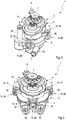
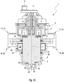
- an actuating device 1 which is intended for the mechanical actuation of a component of a Fig. 6 only partially shown machine 2 is suitable, a housing 3, which is designed in two parts or in several parts and accordingly has at least a first housing part 4 and a second housing part 5. Furthermore, the actuating device 1 has an electric motor 6 arranged in the housing 3, which is provided for driving an actuator 7 arranged on the outside of the housing 3. The actuator 7 in turn serves to couple with the component to be actuated in each case. For example, the actuator 7 has a pin 8 for this purpose.
- the coupling of the electric motor 6 to the actuator 7 takes place in the housing 3 via a multi-stage gear 9 which is connected on the input side to a drive shaft 10 of the electric motor 6 and on the output side to the actuator 7.
- An axis of rotation 11 of the electric motor 6, about which the drive shaft 10 is driven in rotation, defines an axial direction which runs parallel to the axis of rotation 11.
- the adjusting device 1 optionally has a plurality of primary fastening points 12, which serve to fasten the housing 3 to the machine 2.
- three such primary fastening points 12 are provided purely by way of example, which are arranged evenly distributed in the circumferential direction.
- the circumferential direction relates to the axis of rotation 11 and is in the 2 to 4 indicated by a double arrow and designated 13.
- the adjusting device 1 is optionally equipped with at least one secondary fastening point 14, which is used to fasten the first housing part 4 to the second housing part 5.
- the primary and secondary fastening points 12, 14 can also be referred to as primary and secondary fastening means 12, 14 or as primary and secondary fastening devices 12, 14.
- the primary fastening points 12 are also provided for fastening the first housing part 4 to the second housing part 5 in addition to the secondary fastening points 14 when the housing 3 is fastened to the machine 2 with the aid of the primary fastening points 12.
- the two housing parts 4, 5 are thus redundantly fastened to one another, namely on the one hand by means of the secondary fastening points 14 and on the other hand by means of the primary fastening points 12.
- the primary fastening points 12 are each designed as a screw connection 15.
- These screw connections 15 each have a sleeve 16, which contains a through opening 17, through which an only in Fig. 6 shown screw shaft 18 is feasible.
- the respective sleeve 16 has an assembly stop 19 axially at one end and a screw stop 20 axially at the other end.
- the mounting stop 19 is axially supported directly on an assembly point 21 of the machine 2.
- a screw head 22 of a screw 23 having the screw shaft 18 is indirectly supported axially via a washer 24 on the screw stop 20.
- a disc for indirect support can also be arranged between the assembly point 21 and the assembly stop 19.
- the screw 23 is screwed into the machine 2.
- the assembly point 21 has a corresponding threaded opening, not shown here.
- the screw shaft 18 in the form of a threaded rod or stud, which starts from the assembly point 21, in particular is fixedly arranged on the machine 2.
- a corresponding nut is screwed onto this screw shaft 18, which is then axially supported on the screw stop 20 via the washer 24 instead of the screw head 22.
- the aforementioned sleeve 16 of the screw connection 15 is axially divided so that it has a first sleeve part 25 and a second sleeve part 26.
- the first sleeve part 25 is formed on the first housing part 4 and has the mounting stop 19.
- the second sleeve part 26 is formed on the second housing part 5 and has the screw stop 20.
- the first housing part 4 is preferably made of plastic.
- the first sleeve parts 25 are then expediently integrally formed on the first housing part 4.
- the second housing part 5 is preferably a cast part made of plastic or metal. It is preferably a metal part which is characterized by increased heat conduction. A light metal or a light metal alloy, preferably based on aluminum, is preferred.
- the first sleeve part 25 thus preferably consists of plastic and contains a first metal sleeve 27 which defines the mounting stop 19.
- a first metal sleeve 27 which defines the mounting stop 19.
- the first sleeve part 27 is arranged in the injection mold during the injection molding of the first housing part 4, so that it is embedded in a form-fitting manner in the plastic of the first sleeve part 25.
- the second sleeve part 26 made of plastic and equipped with a second metal sleeve 28 which defines the screw stop 20.
- the screw stop 20 is formed on an axial end face of the second metal sleeve 28.
- the second housing part 5 is a metal casting according to the preferred construction here, a separate second metal sleeve 28 can be dispensed with; respectively The second sleeve part 26 can then itself form the second metal sleeve 28.
- the first metal sleeve 27 is axially supported directly on the second metal sleeve 28.
- the secondary fastening points 14 are each designed as a latching connection 29.
- the respective latching connection 29 has a radially resilient latching hook 30 formed on the first housing part 4, here on the first sleeve part 25.
- the respective latching connection 29 has a latching contour 31 formed on the second housing part 5 or here on the second sleeve part 26, which is shaped complementarily to the latching hook 30 and which interacts with the latching hook 30 for fastening the first housing part 4 to the second housing part 5.
- the locking contour 30 is designed here in the form of a locking lug with a ramp.
- the respective latching hook 30 is expediently formed integrally on the first sleeve part 25, while the latching contour 31 is advantageously integrally formed on the second sleeve part 26.
- the catch hook 30 can be seen to engage behind the catch contour 31 axially, as a result of which an efficient positive connection is created in the axial direction, which ensures sufficient fixation of the two housing parts 4, 5 to one another, for example in order to be able to carry out a functional test of the adjusting device 1.
- the housing 3 is fastened to the machine 2
- the primary fastening points 12 take over the fixing function for fixing the two housing parts 4, 5 to one another.
- the holding force can also be used the secondary attachment points 14 are canceled.
- An axial gap 32 can be seen between the latching hook 30 and the latching contour 31, so that no axial forces are transmitted between the latching hook 30 and the latching contour 31 in this assembled state.
- the secondary fastening point 14 or the latching connection 29 does not transmit any axial forces between the first component 4 and the second component 5 and is deactivated to this extent.
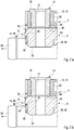
- the primary fastening points 12 each have a first primary contact point 43 and a second primary contact point 44, which face each other axially.
- the first primary contact point 43 is located on an axial end face of the first sleeve part 25 facing the second sleeve part 26.
- the second primary contact point 44 is located on an axial end face of the second sleeve part 26 facing the first sleeve part 25 Fig. 6 are these primary contact points 43, 44 on the metal sleeves 27, 28.
- the secondary fastening points 14 each have a first secondary contact point 45 and a second secondary contact point 46, which face one another axially.
- the first secondary contact point 45 is located on the latching hook 30, while the second secondary contact point 46 is located on the latching contour 31.
- a first case or first state is shown, while in the Fig. 7b and 8b a second case or condition is shown.
- the first case according to the Fig. 7a . 8a fastened the two housing parts 4, 5 to one another by means of the secondary fastening points 14, in the first case the housing 3 is not yet fastened to the machine 2 by means of the primary fastening points 12.
- the first secondary contact points 45 abut the associated second secondary contact points 46, while an axial primary gap 47 is formed between the first primary contact points 43 and the associated second primary contact points 43.
- the two housing parts 4, 5 are again fastened to one another by means of the secondary fastening points 14, the housing 3 in the second case also being fastened to the machine 2 by means of the primary fastening points 12.
- the two housing parts 4, 5 are additionally fastened to one another by the primary fastening points 12.
- an axial secondary gap 48 is formed between the first secondary contact points 45 and the associated second secondary contact points 46, while the first primary contact points 43 abut the associated second primary contact points 44.
- the secondary contact points 45, 46 are not in contact with one another.
- the in Fig. 6 shown state thus corresponds to the second case of Fig. 7b and 8b , Accordingly, the in Fig. 6 shown axial gap 32 the secondary gap 48 of the Fig. 7b and 8b ,
- the second housing part 5 is made of plastic and the second sleeve part 26 integrally formed thereon has a second metal sleeve 28 inserted therein Fig. 7 Example shown, the second housing part 5 made of metal.
- the second metal sleeve 28 is formed by the second sleeve part 26 integrally formed on the second housing part 5.
- Fig. 8 now shows a further embodiment in which the second sleeve part 26, which is integrally formed on the second housing part 5, is formed by a common metal sleeve 49.
- the second housing part 5 made of metal, so that this common metal sleeve 49 is advantageously integrally formed on the second housing part 5.
- it can be provided to provide this common metal sleeve 49 as a separate component, in particular when the second housing part 5 is made of plastic.
- the common metal sleeve 49 can also be designed as an insert and can be integrated into the respective sleeve part 25 or 26.
- This common metal sleeve 49 has the mounting stop 19 axially on the one hand and the screw stop 20 axially on the other hand. Furthermore, this common metal sleeve 49 extends from the second sleeve part 26 through the first sleeve part 25 coaxially. In the case of a separate construction of the common metal sleeve 49, it extends through both sleeve parts 25, 26.
- Fig. 1 The example shown can be formed in the housing 3, a cooling channel 33 through which a liquid coolant can flow. Furthermore, the housing 3 according to the 2 to 4 and 9 to 13 a coolant inlet port 34, which is fluidly connected to the cooling channel 33, and a coolant outlet port 35, which is also fluidly connected to the cooling channel 33.
- the cooling channel 33 is preferably provided on or in the second housing part 5. In the preferred examples of the Fig. 1 . 2 . 4 and 9 to 13, the two connections 34, 35 are also provided on the second housing part 5.
- Fig. 3 shows Fig. 3 a variant in which the one connection, here the coolant inlet connection 34 is formed on the second housing part 5, while the coolant outlet connection 35 is formed on the first housing part 4.
- the cooling channel 33 is integrated into the shape of the second housing part 5.
- the two connections 34, 35 are integral on first housing part 4 or formed on the second housing part 5.
- the connections 34, 35 can also be separate components which are attached to the second housing part 5.
- the second housing part 5 is preferably a metal part in order to be able to transfer the heat generated more quickly to the coolant and to dissipate it from the housing 3.
- connection 34, 35 configured as connection pieces
- Fig. 4 shows an example in which the connections 34, 35 are each configured as a connection flange.
- a screw opening 50 is assigned to the respective connection flange for attachment to a complementary flange, through which a corresponding screw can be passed.
- the cooling duct 33 in the second housing part 5 is axially open on a side facing the first housing part 4.
- This axial channel opening is in Fig. 1 designated 36.
- This axial channel opening 36 extends in the circumferential direction 13, expediently along the entire cooling channel 33.
- the channel opening 36 is axially closed along its entire extent in the circumferential direction 13 by the first housing part 4.
- the cooling duct 33 encloses the electric motor 6 in the circumferential direction 13 over more than 180 °, so that the cooling duct 33 is C-shaped in an axial section.
- the end regions of the cooling duct 33 each communicate with one of the connections 34, 35.
- the cooling duct 33 is interrupted in the circumferential direction 13 between the connections 34, 35.
- a separate outer seal 37 and a separate inner seal 38 are also provided.
- the outer seal 37 runs closed in the circumferential direction 13 and is on a radially remote from the electric motor 6 Side of the cooling channel 33 arranged between the first housing part 4 and the second housing part 5.
- the inner seal 38 also runs closed in the circumferential direction 13 and is arranged on a side of the cooling channel 33 radially facing the electric motor 6 between the first housing part 4 and the second housing part 5.
- the outer seal 37 is inserted into an outer groove 69 lying radially further out, while the inner seal 38 is inserted into an inner groove 70 lying radially further inside.
- the outer seal 37 and the inner seal 38 can also be sections of a common seal which expediently has a web-like connecting section which connects the two sealing sections 37, 38 to one another and which, in the installed state, extends over the open side 36 of the cooling channel 33 extends and axially covers this.
- the second housing part 5 is also a plastic part, an additional seal between the housing parts 4, 5 can be dispensed with.
- a correspondingly liquid-tight connection technology can be used.
- a welded connection or an adhesive connection is conceivable, for example.
- Fig. 1 also see that the cooling duct 33 within the second housing part 5 is axially delimited on a side facing away from the first housing part 4 by a duct bottom 51. Furthermore, it is provided here that the cooling duct 33 leads within the second housing part 5 from the coolant inlet connection 34 in the circumferential direction 13 to the coolant outlet connection 35.
- a biasing spring 52 can be arranged in the second housing part 5, for example in the form of a corrugated spring, which drives or prestresses the electric motor 6 in the direction of the first housing part 4.
- the biasing spring 52 is supported on the one hand on a rear side 53 of the electric motor 6 facing away from the first housing part 4 and on the other hand on a housing bottom 54 of the second housing part 5 facing away from the first housing part 4.
- the biasing spring 52 can be annular and expediently encompass an axial projection 55 of the electric motor 6, which protrudes axially on the rear side 53 thereof.
- the projection 55 can engage in a recess 56 recessed in the housing base 54, in which it is guided in an axially adjustable manner.
- FIG. 5 An electrical connection 39 can be seen, via which the electric motor 6 can be supplied with electrical energy and via which the electric motor 6 can be controlled. If a sensor system or the like is also arranged in the housing 3, for example in order to detect the current rotational position of the actuator 7, a corresponding data line can also be routed via the electrical connection 39.
- the cooling duct 33 expediently extends over more than 180 ° in the circumferential direction 13.
- the cooling duct 33 can extend in the circumferential direction 13 over at least 270 °.
- the cooling channel 33 extends in the circumferential direction 13 over approximately 310 °, while in the example of FIG 16 and 17 extends over about 270 °.
- the second housing part 5 is each made of metal.
- they show Fig. 6 and 14 to 17 Embodiments in which the second housing part 5 is made of plastic.
- the second housing part 5 is designed as a cast metal part, a light metal, preferably a light metal alloy, in particular based on aluminum, being preferred as the metal.
- the cooling duct 33 in this embodiment is provided in the second housing part 5 on the side facing the first housing part 4 with the duct opening 36 and is accordingly axially open and axially closed by the first housing part 4.
- the cooling duct 33 in the cast second housing part 5 can be implemented in a particularly simple manner in an integrated manner.
- the second sleeve part 26 is integrally formed on the second housing part 5 and manages without an additional separate second metal sleeve 28. Rather, the second sleeve part 26 is formed here by the second metal sleeve 28.
- the second housing part 5 has an outer shell 40 made of metal and an inner shell 41 made of metal.
- the inner shell 41 is axially inserted into the outer shell 40, so that the cooling channel 33 is formed radially between the inner shell 41 and the outer shell 40.
- the coolant inlet connection 34 and the coolant outlet connection 35 are provided on the outer shell 40.
- the electric motor 6 is according to the 13 and 14 axially inserted into the inner shell 41.
- the cooling channel 33 can also be realized particularly inexpensively by this shell construction.
- the cooling channel 33 is delimited radially on the inside directly by a peripheral wall 57 of the inner shell 41.
- the cooling duct 33 is delimited radially on the outside by a peripheral wall 58 of the outer shell 40.
- the cooling channel 33 is also axially delimited directly on a side facing the first housing part 4 by a circumferential collar 59 of the inner shell 41.
- On one of the The cooling duct 33 is directly delimited by a bottom 60 of the outer shell 40 on the side facing away from the first housing part 4.
- the inner shell 41 is axially inserted into a bottom opening 61 which is formed in the bottom 60 of the outer shell 40.
- the bottom opening 61 is bordered by an opening edge 62 which bears radially on the inner shell 41 or on its peripheral wall 57 and is tightly connected to it.
- an axial end face 63 of the outer shell 40 lies axially directly against the circumferential collar 59 of the inner shell 41 and is thus tightly connected in a suitable manner.
- Suitable tight connections are, for example, soldered connections or welded connections.
- the inner shell 41 in particular with its peripheral wall 57, can rest directly radially on the electric motor 6 in order to improve the heat transfer.
- the inner shell 41 and the outer shell 40 are designed as shaped sheet metal parts.
- the second sleeve parts 26 or the second metal sleeves 28, which form the second sleeve parts 26, are attached to the inner shell 41 in the form of separate components on the collar 59, for example soldered or welded thereto.
- the connections 34, 35 separate components which are suitably tightly connected to the outer shell 40, for example by soldering or welding.
- an axial seal 64 extending in the circumferential direction 13 can be provided axially between the first housing part 4 and the second housing part 5.
- This axial seal 64 is based on the in Fig. 13 shown embodiment axially from the collar 59.
- the second housing part 5 is formed by the outer shell 40 and the inner shell 41.
- the second housing part 5 is made of metal in this embodiment.
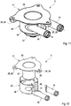
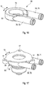
- FIG. 14 shows Fig. 14 an embodiment in which the outer shell 40 and the inner shell 41 form an insert 65 which has the cooling channel 33, the coolant inlet connection 34 and the coolant outlet connection 35.
- This insert 65 is inserted into the second housing part 5, which is expediently made of plastic.
- the coolant inlet connection 34 and the coolant outlet connection 35 are guided through the second housing part 5 to the outside.
- the circumferential axial seal 64 is expediently supported on the second housing part 5 radially outside of the insert 65.
- an insert 65 of this type is also provided, which comprises the coolant inlet connection 34, the coolant outlet connection 35 and the cooling channel 33.
- the connections 34, 35 for the inlet and outlet of the coolant are formed by pipes or pipe sections 71 and 72, while the cooling channel 33 is formed in a C-shaped channel body 73 which connects the two pipe bodies 71, 72 to one another.
- the channel body 73 lies directly radially on the inside of the outside of the electric motor 6.
- the channel body 73 forms a 180 ° deflection or a 180 ° bend, which at its ends merges straight into the straight tube body 71, 72.
- the channel body 73 is preferably curved in the shape of a circular arc.
- the tubular bodies 71, 72 thus extend parallel to one another and their spacing from one another essentially corresponds to the inside diameter of the channel body 73.
- the insert 65 can in principle be as in the example in FIG Fig. 14 be inserted axially or radially into the second housing part 5. However, it is preferred in this example that also in the embodiment of Fig. 14 It can be realized that the second housing part 5 is molded onto this insert 65. In the example of Fig. 15 the shape of the second housing part 5 is such that the insert 65 cannot be used therein. For example, a radially inwardly projecting collar 74 of the second housing part 5 prevents the insert 65 from being inserted axially.
- a first seal 75 which rests radially on the electric motor 6, can seal the second housing part 5 against the electric motor 6 in a first annular groove 76 of the second housing part 5.
- a second seal 77 is provided here, which rests radially on the side of the insert 65 facing the first housing part 4 on the electric motor 6 and thereby seals the electric motor 6 with respect to the first housing 4.
- the second seal 77 is inserted into an annular step 78 of the first housing part 4.
- At least one heat-sensitive electrical component 66 is arranged in the first housing part 4.
- This component 66 is, for example, a sensor for determining the current position or rotational position of the actuator 7.
- this sensor can be designed as a non-contact Hall sensor.
- said component 66 is in the examples of FIG Fig. 10 and 13 arranged in a cooling area 67 of the first housing part 4.
- This cooling area 67 is located in one of the second Housing part 5 facing region of the first housing part 4 and is also arranged here axially aligned with the cooling channel 33.
- this cooling region 67 is arranged here on an inner side of an axial end wall 68 of the first housing part 4 facing away from the second housing part 5.
- the first housing part 4 is in direct contact with the second housing part 5 on an outer side facing the second housing part 5.
- this end wall 68 forms the axial closure for the axially open cooling channel 33.
- the outer seal 37 and the inner seal 38 rest axially on this end wall 68.
Landscapes
- Engineering & Computer Science (AREA)
- Chemical & Material Sciences (AREA)
- Combustion & Propulsion (AREA)
- Mechanical Engineering (AREA)
- General Engineering & Computer Science (AREA)
- Power Engineering (AREA)
- Motor Or Generator Frames (AREA)
Description
- Die vorliegende Erfindung betrifft eine Stellvorrichtung zum mechanischen Betätigen einer Komponente einer Maschine, mit den Merkmalen des Oberbegriffs des Anspruchs 1. Die Erfindung betrifft insbesondere einen Abgasturbolader, der mit einer solchen Stellvorrichtung ausgestattet ist.
- Bei einer Vielzahl von Maschinen gibt es Komponenten, die mechanisch betätigt werden müssen, damit die jeweilige Komponente die ihr zugeordnete Funktion innerhalb der jeweiligen Maschine erfüllen kann. Von bevorzugtem Interesse ist als Maschine hierbei ein Abgasturbolader, der als betätigbare Komponente beispielsweise eine variable Turbinengeometrie oder ein Wastegateventil aufweisen kann. Dementsprechend kann ein derartiger Abgasturbolader mit einer Stellvorrichtung ausgestattet sein, um die variable Turbinengeometrie bzw. das Wastegateventil bedarfsabhängig zu betätigen. Selbstverständlich lassen sich auch andere Maschinen mit derartigen Stellvorrichtungen ausstatten. Beispielsweise kann eine Pumpe eine solche Maschine repräsentieren, die als betätigbare Komponente ein Ventil zum Einstellen eines Volumenstroms aufweist. Mit Hilfe der Stellvorrichtung lässt sich dann das Ventil betätigen. Ebenso ist denkbar, eine Abgasrückführung als Maschine aufzufassen, die als betätigbare Komponente ein Abgasrückführventil zum Einstellen einer Abgasrückführrate aufweist. Auch diese Maschine kann mit einer Stellvorrichtung zum Betätigen des Abgasrückführventils ausgestattet sein.
- Stellvorrichtungen, die sich zum mechanischen Betätigen einer Komponente einer Maschine eignen, umfassen grundsätzlich ein Gehäuse und einen im Gehäuse angeordneten Elektromotor zum Antreiben eines außen am Gehäuse angeordneten Stellglieds, das zum Koppeln mit der jeweiligen, zu betätigenden Komponente vorgesehen ist. Elektromotoren zeichnen sich durch ihre hohe Zuverlässigkeit aus. Im Gehäuse können weitere Bauteile der Stellvorrichtung angeordnet sein, wie beispielsweise ein Getriebe, das antriebsmäßig zwischen einer Antriebswelle des Elektromotors und dem jeweiligen Stellglied angeordnet ist. Ebenso kann im Gehäuse eine Sensorik zum Erkennen einer aktuellen Position oder Drehlage des Stellglieds relativ zum Gehäuse angeordnet sein.
- Je nach Anwendungsfall kann eine derartige Stellvorrichtung relativ hohen Umgebungstemperaturen ausgesetzt sein. Bekanntermaßen hängt die Lebensdauer elektrischer und elektronischer Bauteile stark von der Betriebstemperatur ab; je höher die Betriebstemperatur, desto kürzer die Lebensdauer. Bei einer Stellvorrichtung mit Elektromotor kommt erschwerend hinzu, dass der Elektromotor während seines Betriebs selbst Wärme erzeugt.
- Die Stellvorrichtung ist für eine Montage an der jeweiligen Maschine vorgesehen, deren Komponente mit der Stellvorrichtung betätigt werden soll. Es ist daher zweckmäßig, am Gehäuse einer derartigen Stellvorrichtung zum einen erste bzw. primäre Befestigungsstellen oder Befestigungsmittel oder Befestigungseinrichtungen vorzusehen, mit denen das Gehäuse bzw. die Stellvorrichtung an der jeweiligen Maschine befestigt werden kann.
- Zur Qualitätssicherung kann vorgesehen sein, die Stellvorrichtung vor ihrer Montage an der jeweiligen Maschine im Hinblick auf ihre ordnungsgemäße Funktion zu überprüfen. Bei einem mehrteiligen Gehäuse ist es dabei von Vorteil, wenn die separaten Gehäuseteile für diese Funktionsüberprüfung bereits aneinander befestigt sind. Die Befestigung der Gehäuseteile aneinander im Rahmen der Montage der Stellvorrichtung erleichtert auch die Logistik, nämlich die Lagerhaltung und den Transport, beispielsweise vom Ort der Herstellung zum Ort der Funktionsüberprüfung sowie vom Ort der Funktionsüberprüfung zum Ort der Montage an der jeweiligen Maschine. Dementsprechend können zusätzlich zu den vorstehend genannten primären Befestigungsstellen zweite bzw. sekundäre Befestigungsstellen oder Befestigungsmittel oder Befestigungseinrichtungen vorgesehen sein, die es ermöglichen, die Gehäuseteile aneinander zu befestigen. Problematisch ist dabei der hierzu erforderliche Aufwand im Rahmen der Herstellung der Stellvorrichtung. Werden nämlich zum Beispiel Schraubverbindungen für die primären und sekundären Befestigungsstellen verwendet, müssen für die primären und für die sekundären Befestigungsstellen jeweils entsprechende Durchgangsöffnungen bzw. Gewindeöffnungen vorgesehen werden, wozu vergleichsweise viel Bauraum benötigt wird. Außerdem erhöhen sich dadurch die Kosten, da mehr Bauteile zu verbauen sind und mehr Montageschritte erforderlich sind.
- Aus der
WO 2015/169459 A1 ist ein mit einem Wastegateventil ausgestatteter Abgasturbolader bekannt, dessen Lagergehäuse einen Kühlkanal enthält, wobei eine Zulaufleitung zu diesem Kühlkanal und eine Ablaufleitung von diesem Kühlkanal jeweils durch ein Gehäuse einer Stellvorrichtung zum Betätigen des Wastegateventils hindurchgeführt sind, um so gleichzeitig einen Elektromotor dieser Stellvorrichtung zu kühlen. Anschlüsse für Einlass und Auslass des Kühlmittels sind ebenfalls am Gehäuse der Stellvorrichtung ausgebildet. - Eine gattungsgemäße Stellvorrichtung ist aus der
DE 10 2014 106 517 A1 bekannt. Sie umfasst ein Gehäuse, das ein erstes Gehäuseteil und ein zweites Gehäuseteil aufweist. Im Gehäuse ist ein Elektromotor angeordnet zum Antreiben eines außen am Gehäuse angeordneten Stellglieds zum Koppeln mit der zu betätigenden Komponente. Ferner ist im Gehäuse ein Kühlkanal ausgebildet für ein flüssiges Kühlmittel, der mit einem außen am Gehäuse vorgesehenen Kühlmitteleinlassanschluss und mit einem außen am Gehäuse vorgesehenen Kühlmittelauslassanschluss fluidisch verbunden ist. Der Elektromotor ist im zweiten Gehäuseteil angeordnet und ragt zumindest mit seiner Antriebswelle axial in das erste Gehäuseteil hinein, wobei der Kühlkanal am zweiten Gehäuseteil vorgesehen ist. - Die vorliegende Erfindung beschäftigt sich mit dem Problem, für eine Stellvorrichtung der vorstehend beschriebenen Art eine verbesserte oder zumindest eine andere Ausführungsform anzugeben, die sich durch einen verbesserten Schutz vor Überhitzung auszeichnet und dabei eine preiswerte Herstellbarkeit ermöglicht.
- Dieses Problem wird erfindungsgemäß durch den Gegenstand des unabhängigen Anspruchs gelöst. Vorteilhafte Ausführungsformen sind Gegenstand der abhängigen Ansprüche.
- Die Erfindung beruht auf dem allgemeinen Gedanken, im Gehäuse einen Kühlkanal für ein flüssiges Kühlmittel auszubilden, der mit einem außen am Gehäuse vorgesehenen Kühlmitteleinlassanschluss und mit einem außen am Gehäuse vorgesehenen Kühlmittelauslassanschluss fluidisch verbunden ist. Mit Hilfe eines derartigen Kühlkanals lässt sich sehr effizient Wärme vom Gehäuse abführen, was die thermische Belastung elektrischer und/oder elektronischer Komponenten der Stellvorrichtung erheblich reduziert. Ferner wird vorgeschlagen, das Gehäuse mehrteilig, jedoch zumindest zweiteilig auszugestalten, so dass es ein erstes Gehäuseteil und ein zweites Gehäuseteil aufweist. Zur besonders einfachen Herstellbarkeit der Stellvorrichtung wird außerdem vorgeschlagen, den Elektromotor im zweiten Gehäuseteil anzuordnen, derart, dass er zumindest mit seiner Antriebswelle axial in das erste Gehäuseteil hineinragt. Ferner wird auch der Kühlkanal am zweiten Gehäuseteil vorgesehen, so dass die Wärme gezielt dort abgeführt werden kann, wo sie entsteht bzw. wo sie am meisten stört, nämlich im Bereich des Elektromotors. Des Weiteren wird das erste Gehäuseteil aus Kunststoff hergestellt, wodurch die Stellvorrichtung insgesamt preiswert realisierbar ist. Der Kühlkanal kann im zweiten Gehäuseteil zweckmäßig so angeordnet sein, dass er den Elektromotor in der Umfangsrichtung um mindestens 180° umgreift.
- Besonders vorteilhaft ist eine Weiterbildung, bei welcher die beiden Anschlüsse für Kühlmitteleinlass und Kühlmittelauslass am zweiten Gehäuseteil vorgesehen sind. Die Unterbringung des Kühlkanals und der zugehörigen Anschlüsse bzw. in nur einem der beiden Gehäuseteile vereinfacht die Realisierung einer derartigen aktiven Kühlung der Stellvorrichtung. Alternativ kann auch vorgesehen sein, dass der Kühlmitteleinlassanschluss an dem einen Gehäuseteil vorgesehen ist, während der Kühlmittelauslassanschluss am anderen Gehäuseteil vorgesehen ist. Diese Maßnahme kann die Anpassung an unterschiedliche Einbausituationen vereinfachen.
- Gemäß einer nicht erfindungsgemäßen Ausführungsform kann das zweite Gehäuseteil aus Metall hergestellt sein. Bevorzugt kommen hierbei ein Leichtmetall bzw. eine Leichtmetalllegierung zum Einsatz, beispielsweise auf Aluminiumbasis. In einem derartigen metallischen zweiten Gehäuseteil ergibt sich ein effizienter Wärmestrom vom Elektromotor zum Kühlmittel, was eine entsprechend rasche Ableitung von Wärme ermöglicht. Je schneller die Wärme vom Gehäuse abgeführt werden kann, desto geringer fällt der Temperaturanstieg am Elektromotor aus.
- Besonders vorteilhaft ist eine nicht erfindungsgemäße Ausführungsform, bei der das zweite Gehäuseteil ein Gussteil aus Metall ist. Auch hier kommen Leichtmetall bzw. Leichtmetalllegierungen bevorzugt zum Einsatz. Ein derartiges Gussteil lässt sich besonders preiswert in hohen Stückzahlen realisieren. Das als Gussteil konzipierte zweite Gehäuseteil ist im Unterschied zu einem gebauten zweiten Gehäuseteil nicht mehrteilig, sondern einteilig bzw. in einem Stück hergestellt. Der Kühlkanal kann bei einer nicht erfindungsgemäßen Ausführungsform in das zweite Gehäuseteil, das als Metallteil, insbesondere als Gussteil, ausgestaltet ist, integriert sein. Die Integration des Kühlkanals in das zweite Gehäuseteil bedeutet, dass das Kühlmittel unmittelbar mit dem Werkstoff in Kontakt steht, aus dem das zweite Gehäuseteil besteht.
- Besonders zweckmäßig kann der Kühlkanal im zweiten Gehäuseteil an einer dem ersten Gehäuseteil zugewandten Seite axial offen sein und im montierten Zustand durch das erste Gehäuseteil axial verschlossen sein. Die axial offene Bauweise des Kühlkanals ermöglicht eine Formintegration des Kühlkanals in das Gussteil, ohne dass dazu komplexe Gussformen verwendet werden müssen.
- Bei einer Weiterbildung kann an einer vom Elektromotor abgewandten Seite des Kühlkanals eine in Umfangsrichtung geschlossen umlaufende, vorzugsweise separate Außendichtung axial zwischen dem ersten Gehäuseteil und dem zweiten Gehäuseteil angeordnet sein. Mit Hilfe dieser Dichtung können Leckagen von Kühlmittel nach außen, also in eine Umgebung der Stellvorrichtung vermieden werden.
- Bei einer anderen Weiterbildung kann an einer dem Elektromotor radial zugewandten Seite des Kühlkanals eine in Umfangsrichtung geschlossen umlaufende, vorzugsweise separate, Innendichtung axial zwischen dem ersten Gehäuseteil und dem zweiten Gehäuseteil angeordnet sein. Mit Hilfe einer derartigen Innendichtung kann eine Leckage von Kühlmittel nach innen, also in einem Aufnahmeraum des Gehäuses, in dem der Elektromotor angeordnet ist, vermieden werden. Insbesondere lässt sich dadurch ein preiswerter Elektromotor verwenden, der nicht gegenüber Flüssigkeit abgedichtet ist.
- Bei einer anderen Weiterbildung kann vorgesehen sein, dass der Kühlkanal innerhalb des zweiten Gehäuseteils an einer vom ersten Gehäuseteil abgewandten Seite durch einen Kanalboden axial begrenzt ist, der sich in der Umfangsrichtung entlang des gesamten Kühlkanals erstreckt. Somit ist der Kühlkanal zwischen Kühlmitteleinlass und Kühlmittelauslass nicht axial aus dem zweiten Gehäuseteil herausgeführt. Vorzugsweise kann vorgesehen sein, dass der Kühlkanal innerhalb des zweiten Gehäuseteils das Kühlmittel vom Kühlmitteleinlassanschluss in der Umfangsrichtung zum Kühlmittelauslassanschluss führt. Diese Maßnahme bewirkt insbesondere, dass der Kühlkanal zwischen Kühlmitteleinlass und Kühlmittelauslass ausschließlich innerhalb des zweiten Gehäuseteils verläuft. Zusätzlich oder alternativ kann weiter vorgesehen sein, dass der Kühlkanal an einer dem ersten Gehäuseteil zugewandten Axialseite eine sich in der Umfangsrichtung erstreckende, axial offene Kanalöffnung aufweist, die entlang ihrer gesamten Erstreckung in Umfangsrichtung durch das erste Gehäuseteil axial verschlossen ist.
- Bei einer alternativen Ausführungsform kann das zweite Gehäuseteil eine Außenschale aus Metall und eine Innenschale aus Metall aufweisen. Die Innenschale ist axial in die Außenschale eingesetzt. Der Kühlkanal ist radial zwischen der Innenschale und der Außenschale ausgebildet. Kühlmitteleinlassanschluss und Kühlmittelauslassanschluss sind an der Außenschale ausgebildet. Der Elektromotor ist axial in die Innenschale eingesetzt. Dementsprechend wird hier für das zweite Gehäuseteil eine Schalenbauweise vorgeschlagen, die mit metallischen Schalen auskommt, die sich besonders einfach, und somit preiswert, herstellen lassen. Beispielsweise kann es sich bei den metallischen Schalen um Blechformteile handeln. Die Anschlüsse für das Kühlmittel können separat hergestellt sein und an der Außenschale auf geeignete Weise angebracht sein, beispielsweise mittels Lötverbindungen oder Schweißverbindungen.
- Bei einer vorteilhaften Weiterbildung kann der Kühlkanal radial innen direkt durch eine Umfangswand der Innenschale begrenzt sein, während er radial außen direkt durch eine Umfangswand der Außenschale begrenzt ist. Somit kann eine intensive Kühlung der Innenschale und der Außenschale realisiert werden.
- Bei einer anderen Ausführungsform kann der Kühlkanal axial an einer dem ersten Gehäuseteil zugewandten Seite durch einen umlaufenden Kragen der Innenschale direkt begrenzt sein, während er axial an einer vom ersten Gehäuseteil abgewandten Seite durch einen Boden der Außenschale direkt begrenzt ist. Diese Bauweise führt ebenfalls zu einer intensiven Wärmeabführung von der Innenschale und von der Außenschale. Außerdem hat diese Bauweise den Vorteil, dass der Kühlkanal innerhalb der Schalen hermetisch nach außen abgedichtet werden kann, so dass hinsichtlich des Kühlmittels an sich keine weiteren Dichtungen zwischen erstem Gehäuseteil und zweitem Gehäuseteil erforderlich sind.
- Gemäß einer Weiterbildung kann die Innenschale eine Bodenöffnung axial durchsetzen, die in einem Boden der Außenschale ausgebildet ist. Zusätzlich kann vorgesehen sein, dass ein die Bodenöffnung einfassender Öffnungsrand des Bodens radial an der Innenschale direkt anliegt. Insbesondere kann dort eine geeignete, dichte Verbindung zwischen Innenschale und Außenschale realisiert werden, beispielsweise eine Lötverbindung oder Schweißverbindung. Zusätzlich oder alternativ kann eine axiale Stirnseite der Außenschale axial an einem umlaufenden Kragen der Innenschale direkt anliegen. Auch hier kann im Kontaktbereich eine geeignete, dichte Verbindung zwischen Innenschale und Außenschale realisiert werden, beispielsweise eine Lötverbindung oder Schweißverbindung. Hierdurch besitzt das zweite Gehäuseteil einen besonders preiswerten Aufbau.
- Vorzugsweise kann die Innenschale radial direkt am Elektromotor anliegen, was den Wärmeübergang zwischen Elektromotor und Innenschale erheblich verbessert. Wie bereits erwähnt, handelt es sich bei der Innenschale und bei der Außenschale vorzugsweise um Blechformteile, wobei lediglich die Anschlüsse für das Kühlmittel als separate Bauteile ausgeführt sein können, die an die Außenschale auf geeignete Weise dicht angeschlossen sind. Auch hier können Lötverbindungen und Schweißverbindungen zum Einsatz kommen.
- Als weitere Option kann zwischen dem ersten Gehäuseteil und dem zweiten Gehäuseteil eine in der Umfangsrichtung umlaufende Axialdichtung vorgesehen sein, die sich axial an einem umlaufenden Kragen der Innenschale abstützt. Hierdurch wird ein verbesserter Schutz des vom ersten Gehäuseteil umschlossenen Innenraums des Gehäuses vor Verunreinigungen aus der Umgebung der Stellvorrichtung erreicht.
- Bei einer nicht erfindungsgemäßen Ausführungsform kann das zweite Gehäuseteil aus Metall bestehen und durch die Außenschale und die Innenschale gebildet sein. Hierdurch besitzt das zweite Gehäuseteil insgesamt einen vergleichsweise preiswerten Aufbau.
- Erfindungsgemäß ist ein metallischer Einsatz vorgesehen, der den Kühlkanal, den Kühlmitteleinlassanschluss und den Kühlmittelauslassanschluss aufweist. Dieser Einsatz ist in dem aus Kunststoff hergestellten zweiten Gehäuseteil angeordnet, wobei dann der Kühlmitteleinlassanschluss und der Kühlmittelauslassanschluss durch das zweite Gehäuseteil hindurch nach außen geführt sind. Zweckmäßig können die vorstehend genannte Außenschale und die vorstehend genannte Innenschale diesen Einsatz bilden. Der Einsatz lässt sich jedoch auch auf jede beliebige andere geeignete Weise herstellen. Durch diese Maßnahme wird ein vormontierbarer Einsatz vorgestellt, der den Kühlkanal, den Kühlmitteleinlassanschluss und den Kühlmittelauslassanschluss umfasst. Dieser Einsatz lässt sich besonders einfach dicht herstellen, so dass zusätzliche Abdichtungsmaßnahmen innerhalb des Gehäuses hinsichtlich des Kühlmittels entbehrlich sind. Alle übrigen Funktionen des zweiten Gehäuseteils werden durch den aus Kunststoff hergestellten Bereich des zweiten Gehäuseteils realisiert, wodurch das zweite Gehäuseteil insgesamt preiswert realisierbar ist. Beispielsweise erfolgt die Fixierung der beiden Gehäuseteile aneinander in einem Bereich, in dem das zweite Gehäuseteil aus Kunststoff hergestellt ist.
- Zweckmäßig ist der Einsatz als separates Bauteil in das zweite Gehäuseteil eingesetzt. Hierdurch ergibt sich eine vereinfachte Montage. Alternativ kann auch vorgesehen sein, dass das zweite Gehäuseteil an den Einsatz angespritzt ist. In diesem Fall wird der Einsatz als "Einleger" in der Spritzform zum Herstellen des zweiten Gehäuseteils angeordnet bevor der Kunststoff eingespritzt wird. Auch dies vereinfacht die Herstellung. Zweckmäßig können bei diesem Einsatz die Anschlüsse für Einlass und Auslass als Rohre ausgestaltet sein, die an einen C-förmigen Kanalkörper angebracht sind. Dabei kann ferner vorgesehen sein, dass diese Rohre parallel zueinander verlaufen und jeweils tangential in den Kanalkörper übergehen. Hierdurch besitzt der Kühlkanal einen sehr geringen Durchströmungswiderstand.
- Gemäß einer besonders vorteilhaften Ausführungsform können mehrere primäre Befestigungsstellen zum Befestigen des Gehäuses an der Maschine vorgesehen sein. Ferner kann wenigstens eine sekundäre Befestigungsstelle zum Befestigen des ersten Gehäuseteils am zweiten Gehäuseteil vorgesehen sein. Besonders vorteilhaft ist eine Ausführungsform, bei welcher die primären Befestigungsstellen so ausgestaltet sind, dass sie zusätzlich zu wenigstens einer sekundären Befestigungsstelle das erste Gehäuseteil am zweiten Gehäuseteil befestigen, wenn mit Hilfe der primären Befestigungsstellen das Gehäuse an der Maschine befestigt ist. Hierdurch vereinfacht sich die Handhabung der Stellvorrichtung insbesondere im Hinblick auf eine Funktionsüberprüfung. Mit anderen Worten, solange die Stellvorrichtung nicht mit ihren primären Befestigungsstellen an der Maschine befestigt ist, sind das erste Gehäuseteil und das zweite Gehäuseteil über die wenigstens eine sekundäre Befestigungsstelle aneinander befestigt. Diese Fixierung der beiden Gehäuseteile aneinander mit Hilfe der wenigstens einen sekundären Befestigungsstelle ist dabei ausreichend dimensioniert für eine Funktionsprüfung der Stellvorrichtung und vereinfacht die Lagerung und den Transport der vormontierten Stellvorrichtungen vor ihrer finalen Montage an der jeweiligen Maschine. Sobald jedoch die Stellvorrichtung bzw. deren Gehäuse mit Hilfe der primären Befestigungsstellen an der jeweiligen Maschine befestigt wird, übernehmen die primären Befestigungsstellen auch die Fixierung der beiden Gehäuseteile aneinander. In diesem Zustand, in dem das Gehäuse an der Maschine mittels der primären Befestigungsstellen befestigt ist, wirken die primären Befestigungsstellen somit zusätzlich zu der wenigstens einen sekundären Befestigungsstelle, um die beiden Gehäuseteile aneinander zu fixieren. Dies bedeutet jedoch, dass die sekundären Befestigungsstellen nach dem Festlegen des Gehäuses an der Maschine nicht mehr benötigt werden und insoweit redundant sind. Die primären Befestigungsstellen sind für den ordnungsgemäßen dauerhaften Betrieb der Stellvorrichtung an der jeweiligen Maschine dimensioniert und können insbesondere thermisch bedingte Effekte und Alterungserscheinungen kompensieren. Die primären Befestigungsstellen ermöglichen somit eine deutlich höhere Belastung der Verbindung zwischen den beiden Gehäuseteilen als die wenigstens eine sekundäre Befestigungsstelle, da letztere nur für die Funktionsüberprüfung eine hinreichende Verbindung zwischen den beiden Gehäuseteilen gewährleisten muss. Diese Ausführungsform beruht somit auf dem allgemeinen Gedanken, die primären und sekundären Befestigungsstellen hinsichtlich der Befestigung der beiden Gehäuseteile aneinander redundant auszugestalten.
- Dieser Vorschlag ermöglicht es insbesondere für die jeweilige sekundäre Befestigungsstelle eine preiswerte Lösung zu verwenden, da sie lediglich die Funktionsüberprüfung, nicht jedoch den Dauerbetrieb der Stellvorrichtung an der Maschine gewährleisten muss. Insbesondere kann somit auf eine Schraubverbindung zur Realisierung der jeweiligen sekundären Befestigungsstelle verzichtet werden.
- Besonders vorteilhaft ist eine Ausführungsform, bei der die primären Befestigungsstellen jeweils eine erste Primärkontaktstelle und eine zweite Primärkontaktstelle aufweisen, die einander axial zugewandt sind, und bei der mehrere sekundäre Befestigungsstellen vorgesehen sind, die jeweils eine erste Sekundärkontaktstelle und eine zweite Sekundärkontaktstelle aufweisen, die einander axial zugewandt sind. Die primären und sekundären Befestigungsstellen sind nun hinsichtlich dieser Primärkontaktstellen und dieser Sekundärkontaktstellen so aufeinander abgestimmt, dass ein einem ersten Fall, in dem die beiden Gehäuseteile mittels der sekundären Befestigungsstellen aneinander befestigt sind und das Gehäuse nicht mittels der primären Befestigungsstellen an der Maschine befestigt ist, die ersten Sekundärkontaktstellen an den zugehörigen zweiten Sekundärkontaktstellen anliegen, während zwischen den ersten Primärkontaktstellen und den zugehörigen zweiten Primärkontaktstellen ein axialer Primärspalt ausgebildet ist, und dass in einem zweiten Fall, in dem die beiden Gehäuseteile mittels der sekundären Befestigungsstellen aneinander befestigt sind und das Gehäuse mittels der primären Befestigungsstellen an der Maschine befestigt ist, zwischen den ersten Sekundärkontaktstellen und den zugehörigen zweiten Sekundärkontaktstellen ein axialer Sekundärspalt ausgebildet ist, während die ersten Primärkontaktstellen an den zugehörigen zweiten Primärkontaktstellen anliegen. Hierdurch lässt sich im ersten Fall beispielsweise die jeweilige Funktionsprüfung durchführen, während der zweite Fall am Ende der endgültigen Montage vorliegt. Durch den Sekundärspalt kann eine gewisse axiale Beweglichkeit der beiden Gehäuseteile zueinander erhalten bleiben, beispielsweise um die mittels der Sekundärbefestigungsstellen hergestellte Befestigung der beiden Gehäuseteile aneinander wieder einfach lösen zu können, z.B. falls die Funktionsprüfung einen Bedarf für eine Nacharbeitung aufgezeigt hat.
- Bei einer vorteilhaften Weiterbildung können die primären Befestigungsstellen jeweils als Schraubverbindung ausgestaltet sein, die jeweils eine Hülse mit einer Durchgangsöffnung zum Durchführen eines Schraubenschafts aufweisen. Die jeweilige Hülse ist dabei axial einenends mit einem Montageanschlag und axial anderenends mit einem Schraubanschlag ausgestattet. Mit dem Montageanschlag stützt sich die jeweilige Hülse an einer Montagestelle der Maschine direkt oder über eine Scheibe indirekt ab, wenn das Gehäuse an der Maschine befestigt ist. Am Schraubanschlag stützt sich ein Schraubenkopf einer den Schraubenschaft aufweisenden Schraube oder eine auf den Schraubenschaft aufgeschraubte Mutter direkt oder über eine Scheibe indirekt axial ab. Des Weiteren ist zweckmäßig vorgesehen, dass die jeweilige Hülse axial geteilt ist, derart, dass sie ein den Montageanschlag aufweisendes, am ersten Gehäuseteil ausgebildetes erstes Hülsenteil und ein den Schraubanschlag aufweisendes, am zweiten Gehäuseteil ausgebildetes zweites Hülsenteil aufweist. Beim Befestigen des Gehäuses an der Maschine wird somit der jeweilige Schraubenschaft durch die jeweilige Hülse bzw. durch deren Durchgangsöffnung axial hindurchgesteckt. Die jeweilige Schraubverbindung verspannt dann das erste Gehäuseteil zwischen dem zweiten Gehäuseteil und der Maschine. Im Einzelnen verspannt die jeweilige Schraubverbindung das erste Hülsenteil axial zwischen dem zweiten Hülsenteil und der jeweiligen Montagestelle der Maschine. Hierdurch wird eine formschlüssige und extrem sichere Fixierung des Gehäuses an der Maschine und der beiden Gehäuseteile aneinander erreicht.
- Des Weiteren wird eine Weiterbildung bevorzugt, bei der das erste Gehäuseteil aus Kunststoff hergestellt ist und die ersten Hülsenteile integral am ersten Gehäuseteil ausgeformt sind. Hierdurch lässt sich eine besonders preiswerte Ausgestaltung der Stellvorrichtung im Bereich des ersten Gehäuseteils realisieren. Zusätzlich oder alternativ kann das zweite Gehäuseteil aus Kunststoff oder Metall bestehen und die zweiten Hülsenteile können integral am zweiten Gehäuseteil ausgeformt oder durch an das zweite Gehäuseteil angebaute, separate Bauteile gebildet sein. Die metallische Ausführung des zweiten Gehäuseteils ist insbesondere dann von Interesse, wenn der Kühlkanal unmittelbar im zweiten Gehäuseteil ausgebildet ist.
- Bei einer vorteilhaften Ausführungsform kann das jeweilige erste Hülsenteil aus Kunststoff bestehen und eine den Montageanschluss definierende erste Metallhülse enthalten, die sich am metallisch zweiten Gehäuseteil axial abstützt. Die Integration einer derartigen Metallhülse in ein Kunststoffbauteil lässt sich besonders einfach in Form eines sogenannten "Einlegers" realisieren.
- Bei einer anderen Ausführungsform kann vorgesehen sein, dass bei der jeweiligen Hülse das eine Hülsenteil durch eine gemeinsame Metallhülse gebildet ist oder aus Kunststoff besteht und eine gemeinsame Metallhülse enthält. Diese gemeinsame Metallhülse definiert den Montageanschlag und den Schraubanschlag. Ferner erstreckt sich diese gemeinsame Metallhülse durch das andere Hülsenteil koaxial hindurch. Die Verwendung einer solchen gemeinsamen Metallhülse vereinfacht die Herstellung der Gehäuseteile. Außerdem können die an dem einen Gehäuseteil ausgebildeten gemeinsamen Metallhülsen beim Anbauen des anderen Gehäuseteils als Positionierhilfen verwendet werden.
- Gemäß einer anderen vorteilhaften Ausführungsform können mehrere sekundäre Befestigungsstellen vorgesehen sein, die zweckmäßig jeweils in eine primäre Befestigungsstelle baulich integriert sein können. Durch die Integration der sekundären Befestigungsstellen in die primären Befestigungsstellen benötigen die sekundären Befestigungsstellen am Gehäuse insgesamt deutlich weniger Bauraum als beispielsweise in einem alternativen Fall, bei dem die primären Befestigungsstellen und die sekundären Befestigungsstellen separat ausgeführt und räumlich voneinander getrennt, insbesondere in der Umfangsrichtung zueinander beabstandet entlang des Umfangs der Gehäuseteile angeordnet sind.
- Besonders zweckmäßig ist eine Ausführungsform, bei der mehrere sekundäre Befestigungsstellen vorgesehen sind, die jeweils als Rastverbindung ausgestaltet sind. Die jeweilige Rastverbindung umfasst zweckmäßig einen am ersten Gehäuseteil ausgebildeten, insbesondere radial federnden Rasthaken und eine am zweiten Gehäuseteil ausgebildete Rastkontur, die mit dem Rasthaken zum Befestigen des ersten Gehäuseteils am zweiten Gehäuseteil zusammenwirkt. Insbesondere hintergreift hierzu der Rasthaken axial die zugehörige Rastkontur. Die jeweilige Rastkontur kann dabei als zusätzlich an einer Außenseite des zweiten Gehäuseteils vorgesehener Vorsprung ausgestaltet sein oder durch eine ohnehin an der Außenseite des zweiten Gehäuseteils vorhandene Kante gebildet sein. Derartige Rastverbindungen lassen sich für die Funktionsüberprüfung der Stellvorrichtung hinreichend stabil realisieren und ermöglichen ein besonders einfaches Befestigen der beiden Gehäuseteile aneinander.
- Besonders zweckmäßig ist eine Ausführungsform, bei welcher der jeweilige Rasthaken am ersten Hülsenteil ausgebildet ist, während die jeweilige Rastkontur am zweiten Hülsenteil ausgebildet ist. Hierdurch wird wieder eine Integration der sekundären Befestigungsstellen in die primären Befestigungsstellen erreicht, die besonders platzsparend ist.
- Weiterhin ist eine Ausführungsform von Vorteil, bei der das erste Gehäuseteil aus Kunststoff hergestellt ist und bei der die Rasthaken integral am ersten Gehäuseteil ausgeformt sind. Zusätzlich oder alternativ kann das zweite Gehäuseteil aus Kunststoff oder Metall hergestellt sein und die Rastkonturen können integral am zweiten Gehäuseteil ausgeformt sein. Durch diese Maßnahme lassen sich die Rastverbindungen besonders preiswert realisieren, insbesondere bereits beim Spritzgießen der Gehäuseteile.
- Bevorzugt ist eine Ausführungsform, bei der die Rasthaken integral an den ersten Hülsenteilen ausgeformt sind und bei der die ersten Hülsenteile integral am ersten Gehäuseteil ausgeformt sind. Zusätzlich oder alternativ sind die Rastkonturen integral an den zweiten Hülsenteilen ausgeformt, während die zweiten Hülsenteile integral am zweiten Gehäuseteil ausgeformt sind.
- Besonders vorteilhaft ist eine Ausführungsform, bei der im ersten Gehäuseteil zumindest ein elektrisches Bauteil in einem Kühlbereich angeordnet ist. Dieser Kühlbereich kann sich in einem dem zweiten Gehäuseteil zugewandten Bereich des ersten Gehäuseteils und insbesondere axial fluchtend zum Kühlkanal befinden. Zusätzlich oder alternativ kann sich dieser Kühlbereich an einer vom zweiten Gehäuseteil abgewandten Innenseite einer axialen Stirnwand des ersten Gehäuseteils befinden, die an ihrer dem zweiten Gehäuseteil zugewandten Außenseite direkt mit dem zweiten Gehäuseteil in Kontakt steht. Durch diese Maßnahmen, die alternativ oder kumulativ oder in beliebiger Kombination realisierbar sind, kann die mit Hilfe des Kühlkanals realisierbare Kühlung auch effizient für wenigstens ein elektrisches Bauteil genutzt werden, das im ersten Gehäuseteil angeordnet ist. Beispielsweise kann ein Sensor zum Ermitteln der aktuellen Position oder Drehlage des Stellglieds relativ zum Gehäuse im ersten Gehäuseteil angeordnet sein.
- Weitere wichtige Merkmale und Vorteile der Erfindung ergeben sich aus den Unteransprüchen, aus den Zeichnungen und aus der zugehörigen Figurenbeschreibung anhand der Zeichnungen.
- Es versteht sich, dass die vorstehend genannten und die nachstehend noch zu erläuternden Merkmale nicht nur in der jeweils angegebenen Kombination, sondern auch in anderen Kombinationen oder in Alleinstellung verwendbar sind, ohne den Rahmen der vorliegenden Erfindung zu verlassen.
- Bevorzugte Ausführungsbeispiele der Erfindung sind in den Zeichnungen dargestellt und werden in der nachfolgenden Beschreibung näher erläutert, wobei sich gleiche Bezugszeichen auf gleiche oder ähnliche oder funktional gleiche Komponenten beziehen. Dabei zeigen die
Figuren 1 und9 bis 13 keine erfindungsgemäßen Ausführungsformen. - Es zeigen, jeweils schematisch,
- Fig. 1
- einen Längsschnitt einer Stellvorrichtung,
- Fig. 2-4
- je eine isometrische Ansicht der Stellvorrichtung, jedoch bei verschiedenen Ausführungsformen,
- Fig. 5
- eine isometrische Detailansicht der Stellvorrichtung im Bereich einer primären und sekundären Befestigungsstelle,
- Fig. 6
- einen Längsschnitt im Bereich einer derartigen Befestigungsstelle,
- Fig. 7-8
- je einen Längsschnitt wie in
Fig. 6 , jedoch bei anderen Ausführungsformen und bei verschiedenen Zuständen a und b, - Fig. 9
- einen Querschnitt der Stellvorrichtung im Bereich eines Kühlkanals,
- Fig. 10
- ein Längsschnitt wie in
Fig. 1 , jedoch in einer anderen Schnittebene, - Fig. 11
- eine isometrische Ansicht eines zweiten Gehäuseteils,
- Fig. 12
- eine auseinandergezogene Ansicht des zweiten Gehäuseteils aus
Fig. 11 , - Fig. 13
- ein Längsschnitt der Stellvorrichtung wie in
Fig. 10 , jedoch bei einer anderen Schnittebene und bei dem in denFig. 11 und 12 gezeigten zweiten Gehäuseteil, - Fig. 14-15
- jeweils einen Längsschnitt der Stellvorrichtung wie in den
Fig. 10 , jedoch bei weiteren Ausführungsformen, - Fig. 16
- eine isometrische Ansicht eines Einsatzes ohne zweites Gehäuseteil,
- Fig. 17
- eine isometrische Ansicht des Einsatzes mit zweitem Gehäuseteil.
- Entsprechend den
Fig. 1 bis 17 umfasst eine Stellvorrichtung 1, die sich zum mechanischen Betätigen einer Komponente einer inFig. 6 nur teilweise dargestellten Maschine 2 eignet, ein Gehäuse 3, das zweiteilig oder mehrteilig ausgestaltet ist und dementsprechend zumindest ein erstes Gehäuseteil 4 und ein zweites Gehäuseteil 5 aufweist. Ferner weist die Stellvorrichtung 1 einen im Gehäuse 3 angeordneten Elektromotor 6 auf, der zum Antreiben eines außen am Gehäuse 3 angeordneten Stellglieds 7 vorgesehen ist. Das Stellglied 7 dient seinerseits zum Koppeln mit der jeweils zu betätigenden Komponente. Beispielsweise weist das Stellglied 7 hierzu einen Zapfen 8 auf. Die Kopplung des Elektromotors 6 mit dem Stellglied 7 erfolgt im Gehäuse 3 über ein mehrstufiges Getriebe 9, das eingangsseitig mit einer Antriebswelle 10 des Elektromotors 6 und ausgangsseitig mit dem Stellglied 7 verbunden ist. Eine Rotationsachse 11 des Elektromotors 6, um welche die Antriebswelle 10 drehend angetrieben ist, definiert eine Axialrichtung, die parallel zur Rotationsachse 11 verläuft. - Die Stellvorrichtung 1 weist optional mehrere primäre Befestigungsstellen 12 auf, die zum Befestigen des Gehäuses 3 an der Maschine 2 dienen. Im gezeigten Beispiel sind rein exemplarisch drei derartige primäre Befestigungsstellen 12 vorgesehen, die in der Umfangsrichtung gleichmäßig verteilt angeordnet sind. Die Umfangsrichtung bezieht sich auf die Rotationsachse 11 und ist in den
Fig. 2 bis 4 durch einen Doppelpfeil angedeutet und mit 13 bezeichnet. Ferner ist die Stellvorrichtung 1 optional mit wenigstens einer sekundären Befestigungsstelle 14 ausgestattet, die zum Befestigen des ersten Gehäuseteils 4 am zweiten Gehäuseteil 5 dient. Beim hier gezeigten Beispiel sind mehrere derartige sekundäre Befestigungsstellen 14 vorgesehen, nämlich rein exemplarisch genau drei, die ebenfalls in der Umfangsrichtung 13 gleichmäßig beabstandet verteilt angeordnet sind. Die primären und sekundären Befestigungsstellen 12, 14 können auch als primäre und sekundäre Befestigungsmittel 12, 14 bzw. als primäre und sekundäre Befestigungseinrichtungen 12, 14 bezeichnet werden. - Bei der hier vorgestellten Stellvorrichtung 1 sind die primären Befestigungsstellen 12 außerdem dazu vorgesehen, das erste Gehäuseteil 4 zusätzlich zu den sekundären Befestigungsstellen 14 am zweiten Gehäuseteil 5 zu befestigen, wenn mit Hilfe der primären Befestigungsstellen 12 das Gehäuse 3 an der Maschine 2 befestigt ist. Bei an der Maschine 2 befestigter Stellvorrichtung 1 sind somit die beiden Gehäuseteile 4, 5 redundant aneinander befestigt, nämlich einerseits mittels der sekundären Befestigungsstellen 14 und andererseits mittels der primären Befestigungsstellen 12.
- Bei dem hier gezeigten Beispiel sind die primären Befestigungsstellen 12 jeweils als Schraubverbindung 15 ausgestaltet. Diese Schraubverbindungen 15 weisen jeweils eine Hülse 16 auf, die eine Durchgangsöffnung 17 enthält, durch die ein nur in
Fig. 6 gezeigter Schraubenschaft 18 durchführbar ist. Bezug nehmend aufFig. 6 weist die jeweilige Hülse 16 axial einenends einen Montageanschlag 19 und axial anderenends einen Schraubanschlag 20 auf. Im gezeigten montierten Zustand stützt sich der Montageanschlag 19 axial an einer Montagestelle 21 der Maschine 2 direkt ab. Im Unterschied dazu stützt sich am Schraubanschlag 20 ein Schraubenkopf 22 einer den Schraubenschaft 18 aufweisenden Schraube 23 indirekt über eine Scheibe 24 axial ab. Grundsätzlich kann auch zwischen der Montagestelle 21 und dem Montageanschlag 19 eine Scheibe für eine indirekte Abstützung angeordnet sein. Im Beispiel derFig. 4 ist die Schraube 23 in die Maschine 2 eingeschraubt. Hierzu weist die Montagestelle 21 eine entsprechende, hier nicht gezeigte Gewindeöffnung auf. Alternativ dazu ist es ebenso möglich, den Schraubenschaft 18 in Form einer Gewindestange oder Stiftschraube zu realisieren, die von der Montagestelle 21 ausgeht, insbesondere fest an der Maschine 2 angeordnet ist. In diesem Fall wird auf diesen Schraubenschaft 18 eine entsprechende Mutter aufgeschraubt, die sich dann anstelle des Schraubenkopfs 22 über die Scheibe 24 am Schraubanschlag 20 axial abstützt. - Entsprechend den
Fig. 6 bis 8 ist die zuvor genannte Hülse 16 der Schraubverbindung 15 axial geteilt, so dass sie ein erstes Hülsenteil 25 und ein zweites Hülsenteil 26 aufweist. Das erste Hülsenteil 25 ist am ersten Gehäuseteil 4 ausgebildet und weist den Montageanschlag 19 auf. Das zweite Hülsenteil 26 ist am zweiten Gehäuseteil 5 ausgebildet und weist den Schraubanschlag 20 auf. Vorzugsweise ist das erste Gehäuseteil 4 aus Kunststoff hergestellt. Die ersten Hülsenteile 25 sind dann zweckmäßig integral am ersten Gehäuseteil 4 ausgeformt. Das zweite Gehäuseteil 5 ist vorzugsweise ein Gussteil aus Kunststoff oder Metall. Bevorzugt handelt es sich um ein Metallteil, das sich durch eine erhöhte Wärmeleitung auszeichnet. Bevorzugt kommt dabei ein Leichtmetall bzw. eine Leichtmetalllegierung, vorzugsweise auf Aluminiumbasis, in Betracht. - Gemäß
Fig. 6 besteht das erste Hülsenteil 25 somit vorzugsweise aus Kunststoff und enthält eine erste Metallhülse 27, die den Montageanschlag 19 definiert. Ein axiales Stirnende der ersten Metallhülse 27 bildet hierzu den Montageanschlag 19. Das erste Hülsenteil 27 ist beim Spritzformen des ersten Gehäuseteils 4 in der Spritzform angeordnet, so dass es formschlüssig in den Kunststoff des ersten Hülsenteils 25 eingebettet ist. Im Beispiel derFig. 6 ist auch das zweite Hülsenteil 26 aus Kunststoff hergestellt und mit einer zweiten Metallhülse 28 ausgestattet, die den Schraubanschlag 20 definiert. Hierzu ist der Schraubanschlag 20 an einer axialen Stirnseite der zweiten Metallhülse 28 ausgebildet. Sofern das zweite Gehäuseteil 5 gemäß der hier bevorzugten Bauweise ein Metallgussteil ist, kann auf eine separate zweite Metallhülse 28 verzichtet werden; beziehungsweise kann dann das zweite Hülsenteil 26 selbst die zweite Metallhülse 28 bilden. Im montierten Zustand stützt sich die erste Metallhülse 27 axial an der zweiten Metallhülse 28 direkt ab. - Sofern wie hier die Anzahl an primären Befestigungsstellen 12 und sekundären Befestigungsstellen 14 gleich ist, wird eine Ausführungsform bevorzugt, bei der je eine sekundäre Befestigungsstelle 14 in je eine primäre Befestigungsstelle 12 integriert ist. Hierdurch ergibt sich eine signifikante Bauraumeinsparung entlang des Umfangs des Gehäuses 3.
- Bei den hier gezeigten, bevorzugten Beispielen sind die sekundären Befestigungsstellen 14 jeweils als Rastverbindung 29 ausgestaltet. Die jeweilige Rastverbindung 29 weist einen am ersten Gehäuseteil 4, hier am ersten Hülsenteil 25, ausgebildeten, radial federelastischen Rasthaken 30 auf. Außerdem weist die jeweilige Rastverbindung 29 eine am zweiten Gehäuseteil 5 bzw. hier am zweiten Hülsenteil 26 ausgebildete Rastkontur 31 auf, die komplementär zum Rasthaken 30 geformt ist und die mit dem Rasthaken 30 zum Befestigen des ersten Gehäuseteils 4 am zweiten Gehäuseteil 5 zusammenwirkt. Die Rastkontur 30 ist hier in Form einer Rastnase mit Rampe ausgestaltet. Zweckmäßig ist der jeweilige Rasthaken 30 integral am ersten Hülsenteil 25 ausgeformt, während die Rastkontur 31 zweckmäßig integral am zweiten Hülsenteil 26 ausgebildet ist.
- Erkennbar hintergreift der Rasthaken 30 die Rastkontur 31 axial, wodurch in axialer Richtung ein effizienter Formschluss entsteht, der eine hinreichende Fixierung der beiden Gehäuseteile 4, 5 aneinander gewährleistet, beispielsweise um eine Funktionsprüfung der Stellvorrichtung 1 durchführen zu können. Sobald jedoch, wie in
Fig. 6 gezeigt, das Gehäuse 3 an der Maschine 2 befestigt ist, übernehmen die primären Befestigungsstellen 12 die Fixierfunktion zum Fixieren der beiden Gehäuseteile 4, 5 aneinander. Insbesondere kann dabei auch die Haltekraft der sekundären Befestigungsstellen 14 aufgehoben werden. InFig. 6 ist ein Axialspalt 32 zwischen dem Rasthaken 30 und der Rastkontur 31 erkennbar, so dass in diesem montierten Zustand keine Axialkräfte zwischen Rasthaken 30 und Rastkontur 31 übertragen werden. Mit anderen Worten, die sekundäre Befestigungsstelle 14 bzw. die Rastverbindung 29 überträgt hier keine axialen Kräfte zwischen dem ersten Bauteil 4 und dem zweiten Bauteil 5 und ist insoweit deaktiviert. - Dieses Zusammenspiel von primären Befestigungsstellen 12 und sekundären Befestigungsstellen 14 wird nachfolgend anhand der
Fig. 7 und8 näher erläutert, die sich durch die Ausgestaltung der Hülse 16 und/oder der jeweiligen Metallhülse 27, 28 sowie in der Materialauswahl für das zweite Gehäuseteil 5 voneinander unterscheiden. Darauf wird jedoch noch weiter unten eingegangen. - Gemäß den
Fig. 7 und8 weisen die primären Befestigungsstellen 12 jeweils eine erste Primärkontaktstelle 43 und eine zweite Primärkontaktstelle 44 auf, die einander axial zugewandt sind. Die erste Primärkontaktstelle 43 befindet sich an einer dem zweiten Hülsenteil 26 zugewandten axialen Stirnseite des ersten Hülsenteils 25. Die zweite Primärkontaktstelle 44 befindet sich an einer dem ersten Hülsenteil 25 zugewandten axialen Stirnseite des zweiten Hülsenteils 26. Im Beispiel derFig. 6 befinden sich diese Primärkontaktstellen 43, 44 an den Metallhülsen 27, 28. Die sekundären Befestigungsstellen 14 weisen jeweils eine erste Sekundärkontaktstelle 45 und eine zweite Sekundärkontaktstelle 46 auf, die einander axial zugewandt sind. Die erste Sekundärkontaktstelle 45 befindet sich am Rasthaken 30, während sich die zweite Sekundärkontaktstelle 46 an der Rastkontur 31 befindet. In denFig. 7a und8a ist jeweils ein erster Fall oder erster Zustand dargestellt, während in denFig. 7b und8b jeweils ein zweiter Fall oder Zustand dargestellt ist. Im ersten Fall sind gemäß denFig. 7a ,8a die beiden Gehäuseteile 4, 5 mittels der sekundären Befestigungsstellen 14 aneinander befestigt, wobei im ersten Fall das Gehäuse 3 noch nicht mittels der primären Befestigungsstellen 12 an der Maschine 2 befestigt ist. In diesem ersten Fall liegen die ersten Sekundärkontaktstellen 45 an den zugehörigen zweiten Sekundärkontaktstellen 46 an, während zwischen den ersten Primärkontaktstellen 43 und den zugehörigen zweiten Primärkontaktstellen 43 ein axialer Primärspalt 47 ausgebildet ist. Mit anderen Worten, im ersten Fall liegen die Primärkontaktstellen 43, 44 nicht aneinander an. Im zweiten Fall sind gemäß denFig. 7b und8b die beiden Gehäuseteile 4, 5 wieder mittels der sekundären Befestigungsstellen 14 aneinander befestigt, wobei das Gehäuse 3 im zweiten Fall außerdem mittels der primären Befestigungsstellen 12 an der Maschine 2 befestigt ist. Wie vorstehend beschrieben, sind die beiden Gehäuseteile 4, 5 in diesem zweiten Fall zusätzlich auch durch die Primärbefestigungsstellen 12 aneinander befestigt. In diesem zweiten Fall ist zwischen den ersten Sekundärkontaktstellen 45 und den zugehörigen zweiten Sekundärkontaktstellen 46 ein axialer Sekundärspalt 48 ausgebildet, während die ersten Primärkontaktstellen 43 an den zugehörigen zweiten Primärkontaktstellen 44 anliegen. Mit anderen Worten, im zweiten Fall liegen die Sekundärkontaktstellen 45, 46 nicht aneinander an. Der inFig. 6 gezeigte Zustand entspricht somit dem zweiten Fall derFig. 7b und8b . Dementsprechend entspricht der inFig. 6 gezeigte Axialspalt 32 dem Sekundärspalt 48 derFig. 7b und8b . - Während bei dem in
Fig. 6 gezeigten Beispiel das zweite Gehäuseteil 5 aus Kunststoff hergestellt ist und das daran integral ausgebildete zweite Hülsenteil 26 eine darin eingesetzte zweite Metallhülse 28 aufweist, ist bei dem inFig. 7 gezeigten Beispiel das zweite Gehäuseteil 5 aus Metall hergestellt. Die zweite Metallhülse 28 ist dabei durch das integral am zweiten Gehäuseteil 5 ausgeformte zweite Hülsenteil 26 gebildet. -
Fig. 8 zeigt nun eine weitere Ausführungsform, bei der das zweite Hülsenteil 26, das integral am zweiten Gehäuseteil 5 ausgeformt ist, durch eine gemeinsame Metallhülse 49 gebildet ist. Im Beispiel derFig. 8 ist das zweite Gehäuseteil 5 aus Metall hergestellt, so dass zweckmäßig diese gemeinsame Metallhülse 49 integral am zweiten Gehäuseteil 5 ausgeformt ist. Bei einer anderen Ausführungsform kann dagegen vorgesehen sein, diese gemeinsame Metallhülse 49 als separates Bauteil vorzusehen, insbesondere dann, wenn das zweite Gehäuseteil 5 aus Kunststoff hergestellt ist. Dann kann auch die gemeinsame Metallhülse 49 als Einleger ausgestaltet und in das jeweilige Hülsenteil 25 oder 26 eingebunden sein. Diese gemeinsame Metallhülse 49 weist axial einerseits den Montageanschlag 19 und axial andererseits den Schraubanschlag 20 auf. Ferner erstreckt sich diese gemeinsame Metallhülse 49 ausgehend vom zweiten Hülsenteil 26 durch das erste Hülsenteil 25 koaxial hindurch. Bei separater Bauweise der gemeinsamen Metallhülse 49 erstreckt sich diese durch beide Hülsenteile 25, 26 hindurch. - Zurückkommend auf das in
Fig. 1 gezeigte Beispiel kann im Gehäuse 3 ein Kühlkanal 33 ausgebildet sein, der von einem flüssigen Kühlmittel durchströmbar ist. Ferner finden sich am Gehäuse 3 gemäß denFig. 2 bis 4 und9 bis 13 ein Kühlmitteleinlassanschluss 34, der mit dem Kühlkanal 33 fluidisch verbunden ist, sowie ein Kühlmittelauslassanschluss 35, der ebenfalls mit dem Kühlkanal 33 fluidisch verbunden ist. Vorzugsweise ist der Kühlkanal 33 am bzw. im zweiten Gehäuseteil 5 vorgesehen. In den bevorzugten Beispielen derFig. 1 ,2 ,4 und9 bis 13 sind außerdem die beiden Anschlüsse 34, 35 am zweiten Gehäuseteil 5 vorgesehen. Im Unterschied dazu zeigtFig. 3 eine Variante, bei welcher der eine Anschluss, hier der Kühlmitteleinlassanschluss 34 am zweiten Gehäuseteil 5 ausgebildet ist, während der Kühlmittelauslassanschluss 35 am ersten Gehäuseteil 4 ausgebildet ist. Insbesondere ist der Kühlkanal 33 dabei in das zweite Gehäuseteil 5 formintegriert. Ferner sind die beiden Anschlüsse 34, 35 integral am ersten Gehäuseteil 4 bzw. am zweiten Gehäuseteil 5 ausgeformt. Alternativ können die Anschlüsse 34, 35 auch separate Bauteile sein, die an das zweite Gehäuseteil 5 angebaut sind. Sofern ein derartiger Kühlkanal 33 vorgesehen ist, handelt es sich beim zweiten Gehäuseteil 5 bevorzugt um ein Metallteil, um die anfallende Wärme rascher auf das Kühlmittel übertragen und vom Gehäuse 3 abführen zu können. - In den Beispielen der
Fig. 2 und3 sind die besagten Anschlüsse 34, 35 als Anschlussstutzen ausgestaltet, währendFig. 4 ein Beispiel zeigt, bei dem die Anschlüsse 34, 35 jeweils als Anschlussflansch ausgestaltet sind. Dem jeweiligen Anschlussflansch ist zur Befestigung an einem dazu komplementären Flansch jeweils eine Schrauböffnung 50 zugeordnet, durch die eine entsprechende Schraube durchführbar ist. - Wie sich
Fig. 1 entnehmen lässt, ist der Kühlkanal 33 im zweiten Gehäuseteil 5 an einer dem ersten Gehäuseteil 4 zugewandten Seite axial offen. Diese axiale Kanalöffnung ist inFig. 1 mit 36 bezeichnet. Diese axiale Kanalöffnung 36 erstreckt sich in der Umfangsrichtung 13, zweckmäßig entlang des gesamten Kühlkanals 33. Ferner ist die Kanalöffnung 36 entlang ihrer gesamten Erstreckung in Umfangsrichtung 13 durch das erste Gehäuseteil 4 axial verschlossen. Der Kühlkanal 33 umschließt den Elektromotor 6 in der Umfangsrichtung 13 über mehr als 180°, so dass der Kühlkanal 33 in einem Axialschnitt C-förmig ist. Die Endbereiche des Kühlkanals 33 kommunizieren mit je einem der Anschlüsse 34, 35. In der Umfangrichtung 13 zwischen den Anschlüssen 34, 35 ist der Kühlkanal 33 unterbrochen. - Gemäß
Fig. 1 sind außerdem eine separate Außendichtung 37 und eine separate Innendichtung 38 vorgesehen. Die Außendichtung 37 läuft in der Umfangsrichtung 13 geschlossen um und ist an einer vom Elektromotor 6 radial abgewandten Seite des Kühlkanals 33 zwischen dem ersten Gehäuseteil 4 und dem zweiten Gehäuseteil 5 angeordnet. Die Innendichtung 38 läuft ebenfalls in der Umfangsrichtung 13 geschlossen um und ist an einer dem Elektromotor 6 radial zugewandten Seite des Kühlkanals 33 zwischen dem ersten Gehäuseteil 4 und dem zweiten Gehäuseteil 5 angeordnet. Diese als separate Bauteile realisierten Dichtungen 37, 38 sind hier in ringförmig umlaufende Nuten 69, 70 eingesetzt, die im zweiten Gehäuseteil 5 ausgebildet sind. Im Einzelnen ist die Außendichtung 37 in eine radial weiter außen liegende Außennut 69 eingesetzt, während die Innendichtung 38 in eine radial weiter innen liegende Innennut 70 eingesetzt ist. Außendichtung 37 und Innendichtung 38 können bei einer anderen, hier nicht gezeigten Ausführungsform auch Abschnitte einer gemeinsamen Dichtung sein, die zweckmäßig einen stegartigen Verbindungsabschnitt aufweist, der die beiden Dichtungsabschnitte 37, 38 miteinander verbindet und der sich im eingebauten Zustand über die offene Seite 36 des Kühlkanals 33 erstreckt und diesen axial abdeckt. - Sofern es sich beim zweiten Gehäuseteil 5 ebenfalls um ein Kunststoffteil handelt, kann auf eine zusätzliche Dichtung zwischen den Gehäuseteilen 4, 5 verzichtet werden. Beispielsweise kann eine entsprechend flüssigkeitsdichte Verbindungstechnik zum Einsatz kommen. Denkbar ist bspw. eine Schweißverbindung oder eine Klebverbindung.
- Ferner lässt sich
Fig. 1 außerdem entnehmen, dass der Kühlkanal 33 innerhalb des zweiten Gehäuseteils 5 an einer vom ersten Gehäuseteil 4 abgewandten Seite durch einen Kanalboden 51 axial begrenzt ist. Des Weiteren ist hier vorgesehen, dass der Kühlkanal 33 innerhalb des zweiten Gehäuseteils 5 vom Kühlmitteleinlassanschluss 34 in der Umfangsrichtung 13 zum Kühlmittelauslassanschluss 35 führt. - Gemäß
Fig. 1 kann im zweiten Gehäuseteil 5 außerdem eine Vorspannfeder 52 angeordnet sein, z.B. in Form einer Wellfeder, die den Elektromotor 6 in Richtung zum ersten Gehäuseteil 4 antreibt bzw. vorspannt. Hierzu stützt sich die Vorspannfeder 52 einerseits an einer vom ersten Gehäuseteil 4 abgewandten Rückseite 53 des Elektromotors 6 und andererseits an einem vom ersten Gehäuseteil 4 abgewandten Gehäuseboden 54 des zweiten Gehäuseteils 5 ab. Die Vorspannfeder 52 kann ringförmig ausgestaltet sein und zweckmäßig einen axialen Vorsprung 55 des Elektromotors 6 umgreifen, der an dessen Rückseite 53 axial vorsteht. Im Beispiel kann der Vorsprung 55 in eine im Gehäuseboden 54 ausgesparte Vertiefung 56 eingreifen, in der er axial verstellbar geführt ist. - In
Fig. 5 ist ein elektrischer Anschluss 39 erkennbar, über den der Elektromotor 6 mit elektrischer Energie versorgt werden kann und über den der Elektromotor 6 angesteuert werden kann. Sofern im Gehäuse 3, außerdem eine Sensorik oder dergleichen angeordnet ist, beispielsweise um die aktuelle Drehlage des Stellglieds 7 zu detektieren, kann über den Elektroanschluss 39 auch eine entsprechende Datenleitung geführt sein. - Wie sich insbesondere den
Fig. 9 ,16 und 17 entnehmen lässt, erstreckt sich der Kühlkanal 33 zweckmäßig über mehr als 180° in der Umfangsrichtung 13. Insbesondere kann sich der Kühlkanal 33 in der Umfangsrichtung 13 über mindestens 270° erstrecken. Im Beispiel derFig. 9 erstreckt sich der Kühlkanal 33 in der Umfangsrichtung 13 über etwa 310°, während er sich im Beispiel derFig. 16 und 17 über etwa 270° erstreckt. - In den Beispielen der
Fig. 1 bis 5 und7 bis 10 einerseits und derFig. 11 bis 13 andererseits ist das zweite Gehäuseteil 5 jeweils aus Metall hergestellt. Im Unterschied dazu zeigen dieFig. 6 und14 bis 17 Ausführungsformen, bei denen das zweite Gehäuseteil 5 aus Kunststoff hergestellt ist. - Im Beispiel der
Fig. 1 bis 5 und7 bis 10 ist das zweite Gehäuseteil 5 als Metallgussteil konzipiert, wobei hier als Metall ein Leichtmetall, vorzugsweise eine Leichtmetalllegierung, insbesondere auf Aluminiumbasis, bevorzugt ist. Wie erwähnt ist der Kühlkanal 33 bei dieser Ausführungsform im zweiten Gehäuseteil 5 an der dem ersten Gehäuseteil 4 zugewandten Seite mit der Kanalöffnung 36 versehen und dementsprechend axial offen und durch das erste Gehäuseteil 4 axial verschlossen. Hierdurch kann der Kühlkanal 33 im gegossenen zweiten Gehäuseteil 5 besonders einfach formintegriert realisiert werden. - In den
Fig. 8 bis 10 ist außerdem erkennbar, wie das zweite Hülsenteil 26 integral am zweiten Gehäuseteil 5 ausgeformt ist und dabei ohne zusätzliche separate zweite Metallhülse 28 auskommt. Vielmehr ist das zweite Hülsenteil 26 hier durch die zweite Metallhülse 28 gebildet. - In den Beispielen der
Fig. 11 bis 14 weist das zweite Gehäuseteil 5 eine Außenschale 40 aus Metall und eine Innenschale 41 aus Metall auf. Die Innenschale 41 ist axial in die Außenschale 40 eingesetzt, so dass der Kühlkanal 33 radial zwischen der Innenschale 41 und der Außenschale 40 ausgebildet ist. Der Kühlmitteleinlassanschluss 34 und der Kühlmittelauslassanschluss 35 sind an der Außenschale 40 vorgesehen. Der Elektromotor 6 ist gemäß denFig. 13 und 14 axial in die Innenschale 41 eingesetzt. Durch diese Schalenbauweise lässt sich der Kühlkanal 33 ebenfalls besonders preiswert realisieren. - Gemäß den
Fig. 11 bis 14 ist der Kühlkanal 33 radial innen direkt durch eine Umfangswand 57 der Innenschale 41 begrenzt. Radial außen ist der Kühlkanal 33 durch eine Umfangswand 58 der Außenschale 40 begrenzt. Der Kühlkanal 33 ist des Weiteren axial an einer dem ersten Gehäuseteil 4 zugewandten Seite durch einen umlaufenden Kragen 59 der Innenschale 41 direkt begrenzt. An einer vom ersten Gehäuseteil 4 abgewandten Seite ist der Kühlkanal 33 durch einen Boden 60 der Außenschale 40 direkt begrenzt. - Bei der in den
Fig. 11 bis 13 gezeigten Ausführungsform ist die Innenschale 41 in eine Bodenöffnung 61 axial eingesetzt, die im Boden 60 der Außenschale 40 ausgebildet ist. Die Bodenöffnung 61 ist dabei von einem Öffnungsrand 62 eingefasst, der radial an der Innenschale 41 bzw. an deren Umfangswand 57 direkt anliegt und damit dicht verbunden ist. Ferner liegt eine axiale Stirnseite 63 der Außenschale 40 axial an dem umlaufenden Kragen 59 der Innenschale 41 direkt an und ist damit auf geeignete Weise dicht verbunden. Geeignete dichte Verbindungen sind beispielsweise Lötverbindungen oder Schweißverbindungen. - Bei den Ausführungsformen der
Fig. 11 bis 14 kann die Innenschale 41, insbesondere mit ihrer Umfangswand 57, direkt radial am Elektromotor 6 anliegen, um die Wärmeübertragung zu verbessern. Bei beiden Ausführungsformen sind die Innenschale 41 und die Außenschale 40 als Blechformteile konzipiert. An die Innenschale 41 sind die zweiten Hülsenteile 26 bzw. die zweiten Metallhülsen 28, welche die zweiten Hülsenteile 26 bilden, in Form separater Bauteile am Kragen 59 angebracht, beispielsweise damit verlötet oder verschweißt. In beiden Beispielen derFig. 11 bis 14 sind die Anschlüsse 34, 35 separate Bauteile, die auf geeignete Weise dicht mit der Außenschale 40 verbunden sind, beispielsweise durch Verlöten oder Verschweißen. - Wie sich den
Fig. 13 und 14 entnehmen lässt, kann axial zwischen dem ersten Gehäuseteil 4 und dem zweiten Gehäuseteil 5 eine in der Umfangsrichtung 13 umlaufende Axialdichtung 64 vorgesehen sein. Diese Axialdichtung 64 stützt sich bei der inFig. 13 gezeigten Ausführungsform axial am Kragen 59 ab. - Im Beispiel der
Fig. 11 bis 13 ist das zweite Gehäuseteil 5 durch die Außenschale 40 und die Innenschale 41 gebildet. Somit besteht das zweite Gehäuseteil 5 bei dieser Ausführungsform aus Metall. - Im Unterschied dazu zeigt
Fig. 14 eine Ausführungsform, bei der die Außenschale 40 und die Innenschale 41 einen Einsatz 65 bilden, der den Kühlkanal 33, den Kühlmitteleinlassanschluss 34 und den Kühlmittelauslassanschluss 35 aufweist. Dieser Einsatz 65 ist in das zweite Gehäuseteil 5 eingesetzt, das zweckmäßig aus Kunststoff hergestellt ist. Dabei sind der Kühlmitteleinlassanschluss 34 und der Kühlmittelauslassanschluss 35 durch das zweite Gehäuseteil 5 hindurch nach außen geführt. Dementsprechend ist bei der inFig. 14 gezeigten Ausführungsform die umlaufende Axialdichtung 64 zweckmäßig am zweiten Gehäuseteil 5 radial außerhalb des Einsatzes 65 abgestützt. - Bei der in den
Fig. 15 bis 17 gezeigten Ausführungsform ist ebenfalls ein derartiger Einsatz 65 vorgesehen, der den Kühlmitteleinlassanschluss 34, den Kühlmittelauslassanschluss 35 und den Kühlkanal 33 umfasst. Hierbei sind die Anschlüsse 34, 35 für Einlass und Auslass des Kühlmittels durch Rohre bzw. Rohrstücke 71 und 72 gebildet, während der Kühlkanal 33 in einem C-förmigen Kanalkörper 73 ausgebildet ist, der die beiden Rohrkörper 71, 72 miteinander verbindet. Der Kanalkörper 73 liegt radial innen an der Außenseite des Elektromotors 6 unmittelbar an. Im bevorzugten Beispiel bildet der Kanalkörper 73 eine 180°-Umlenkung bzw. einen 180°-Bogen, der an seinen Enden gerade in die geradlinigen Rohrkörper 71, 72 übergeht. Der Kanalkörper 73 ist vorzugsweise kreisbogenförmig gekrümmt. Die Rohrkörper 71, 72 erstrecken sich somit parallel zueinander und ihr Abstand voneinander entspricht im Wesentlichen dem Innendurchmesser des Kanalkörpers 73. Der Einsatz 65 kann grundsätzlich wie im Beispiel derFig. 14 in das zweite Gehäuseteil 5 axial oder radial eingesetzt sein. Bevorzugt ist jedoch bei diesem Beispiel, das auch bei der Ausführungsform derFig. 14 realisierbar ist, dass das zweite Gehäuseteil 5 an diesen Einsatz 65 angespritzt ist. Im Beispiel derFig. 15 ist die Formgebung des zweiten Gehäuseteils 5 so, dass der Einsatz 65 nicht darin einsetzbar ist. Z.B. verhindert ein radial nach innen ragender Kragen 74 des zweiten Gehäuseteils 5 ein axiales Einsetzen des Einsatzes 65. - Gemäß
Fig. 15 kann an einer vom ersten Gehäuseteil 4 abgewandten Seite des Einsatzes 65 eine am Elektromotor 6 radial anliegende erste Dichtung 75 in einer ersten Ringnut 76 des zweiten Gehäuseteils 5 das zweite Gehäuseteil 5 gegenüber dem Elektromotor 6 abdichten. Außerdem ist hier eine zweite Dichtung 77 vorgesehen, die an einer dem ersten Gehäuseteil 4 zugewandten Seite des Einsatzes 65 am Elektromotor 6 radial anliegt und dabei den Elektromotor 6 gegenüber dem ersten Gehäuse 4 abdichtet. Die zweite Dichtung 77 ist dabei in eine Ringstufe 78 des ersten Gehäuseteils 4 eingesetzt. - Obwohl die sekundären Befestigungsstellen 14 nur in den Beispielen der
Fig. 1 bis 8 erkennbar sind, ist klar, dass auch bei den Beispielen derFig. 9 bis 17 derartige sekundäre Befestigungsstellen 14 vorgesehen sein können, die ebenfalls als Rastverbindungen 29 ausgestaltet sein können und die insbesondere in die primären Befestigungsstellen 12 integriert sein können, die zweckmäßig als Schraubverbindungen 15 ausgestaltet sind. - Gemäß den
Fig. 10 und13 ist im ersten Gehäuseteil 4 zumindest ein hitzeempfindliches elektrisches Bauteil 66 angeordnet. Bei diesem Bauteil 66 handelt es sich beispielsweise um einen Sensor zum Ermitteln der aktuellen Position bzw. Drehlage des Stellglieds 7. Beispielsweise kann dieser Sensor als berührungslos arbeitender Hall-Sensor ausgestaltet sein. Jedenfalls ist besagtes Bauteil 66 in den Beispielen derFig. 10 und13 in einem Kühlbereich 67 des ersten Gehäuseteils 4 angeordnet. Dieser Kühlbereich 67 befindet sich dabei in einem dem zweiten Gehäuseteil 5 zugewandten Bereich des ersten Gehäuseteils 4 und ist hier außerdem axial fluchtend zum Kühlkanal 33 angeordnet. Ferner ist dieser Kühlbereich 67 hier an einer vom zweiten Gehäuseteil 5 abgewandten Innenseite einer axialen Stirnwand 68 des ersten Gehäuseteils 4 angeordnet. Mit dieser Stirnwand 68 steht das erste Gehäuseteil 4 an einer dem zweiten Gehäuseteil 5 zugewandten Außenseite unmittelbar mit dem zweiten Gehäuseteil 5 in Kontakt. Beispielsweise bildet diese Stirnwand 68 den axialen Verschluss für den axial offenen Kühlkanal 33. Ferner liegen die Außendichtung 37 und die Innendichtung 38 axial an dieser Stirnwand 68 an.
Claims (14)
- Stellvorrichtung zum mechanischen Betätigen einer Komponente einer Maschine (2),- mit einem Gehäuse (3), das ein erstes Gehäuseteil (4) und ein zweites Gehäuseteil (5) aufweist,- mit einem im Gehäuse (3) angeordneten Elektromotor (6) zum Antreiben eines außen am Gehäuse (3) angeordneten Stellglieds (7) zum Koppeln mit der zu betätigenden Komponente,- mit einem im zweiten Gehäuseteil (5) ausgebildeten Kühlkanal (33) für ein flüssiges Kühlmittel, der mit einem außen am Gehäuse (3) vorgesehenen Kühlmitteleinlassanschluss (34) und mit einem außen am Gehäuse (3) vorgesehenen Kühlmittelauslassanschluss (35) fluidisch verbunden ist,- wobei der Elektromotor (6) im zweiten Gehäuseteil (5) angeordnet ist und zumindest mit seiner Antriebswelle (10) axial in das erste Gehäuseteil (4) hineinragt, dadurch gekennzeichnet,- dass die beiden Gehäuseteile (4, 5) aus Kunststoff hergestellt sind,- dass ein den Kühlkanal (33), den Kühlmitteleinlassanschluss (34) und den Kühlmittelauslassanschluss (35) aufweisender Einsatz (65) vorgesehen ist, der in dem zweiten Gehäuseteil (5) angeordnet ist,- dass der Kühlmitteleinlassanschluss (34) und der Kühlmittelauslassanschluss (35) durch das zweite Gehäuseteil (5) nach außen geführt sind.
- Stellvorrichtung nach Anspruch 1,
dadurch gekennzeichnet,
dass der Kühlkanal (33) im zweiten Gehäuseteil (5) an einer dem ersten Gehäuseteil (4) zugewandten Seite axial offen ist und durch das erste Gehäuseteil (4) axial verschlossen ist. - Stellvorrichtung nach Anspruch 2,
dadurch gekennzeichnet,
dass an einer vom Elektromotor (6) abgewandten Seite des Kühlkanals (33) eine in Umfangsrichtung (13) geschlossen umlaufende Außendichtung (37) axial zwischen dem ersten Gehäuseteil (4) und dem zweiten Gehäuseteil (5) angeordnet ist. - Stellvorrichtung nach Anspruch 2 oder 3,
dadurch gekennzeichnet,
dass an einer dem Elektromotor (6) zugewandten Seite des Kühlkanals (33) eine in Umfangsrichtung (13) geschlossen umlaufende Innendichtung (38) axial zwischen dem ersten Gehäuseteil (4) und dem zweiten Gehäuseteil (5) angeordnet ist. - Stellvorrichtung nach einem der Ansprüche 1 bis 4,
dadurch gekennzeichnet,
dass der Kühlkanal (33) innerhalb des zweiten Gehäuseteils (5) an einer vom ersten Gehäuseteil (4) abgewandten Seite durch einen Kanalboden (51) axial begrenzt ist, der am zweiten Gehäuseteil (5) integral ausgeformt ist. - Stellvorrichtung nach einem der Ansprüche 1 bis 5,
dadurch gekennzeichnet,
dass der Kühlkanal (33) innerhalb des zweiten Gehäuseteils (5) vom Kühlmitteleinlassanschluss (34) in der Umfangsrichtung (13) zum Kühlmittelauslassanschluss (35) führt. - Stellvorrichtung nach einem der Ansprüche 1 bis 6,
dadurch gekennzeichnet,
dass der Kühlkanal (33) an einer dem ersten Gehäuseteil (4) zugewandten Axialseite eine sich in der Umfangsrichtung (13) erstreckende, axial offene Kanalöffnung (36) aufweist, die entlang ihrer gesamten Erstreckung in Umfangsrichtung (13) durch das erste Gehäuseteil (4) axial verschlossen ist. - Stellvorrichtung nach einem der Ansprüche 1 bis 7,
dadurch gekennzeichnet,- dass das zweite Gehäuseteil (5) eine Außenschale (40) aus Metall und eine Innenschale (41) aus Metall aufweist,
dass die Innenschale (41) axial in die Außenschale (40) eingesetzt ist,- dass der Kühlkanal (33) radial zwischen der Innenschale (41) und der Außenschale (40) ausgebildet ist,- dass der Kühlmitteleinlassanschluss (34) und der Kühlmittelauslassanschluss (35) an der Außenschale (40) ausgebildet sind,- dass der Elektromotor (6) axial in die Innenschale (41) eingesetzt ist. - Stellvorrichtung nach einem der Ansprüche 1 bis 8,
dadurch gekennzeichnet,
dass dieser Einsatz (65) durch besagte Innenschale (41) und Außenschale (40) gebildet ist. - Stellvorrichtung nach einem der Ansprüche 1 bis 9,
dadurch gekennzeichnet,
dass der Einsatz (65) in das zweite Gehäuseteil (5) eingesetzt ist. - Stellvorrichtung nach einem der Ansprüche 1 bis 9,
dadurch gekennzeichnet,
dass das zweite Gehäuseteil (5) an den Einsatz (65) angespritzt ist. - Stellvorrichtung nach einem der Ansprüche 1 bis 11,
dadurch gekennzeichnet,- dass mehrere primäre Befestigungsstellen (12) zum Befestigen des Gehäuses (3) an der Maschine (2) vorgesehen sind,- dass wenigstens eine sekundäre Befestigungsstelle (14) zum Befestigen des ersten Gehäuseteils (4) am zweiten Gehäuseteil (5) vorgesehen ist,- dass die primären Befestigungsstellen (12), wenn damit das Gehäuse (3) an der Maschine (2) befestigt ist, zusätzlich zur wenigstens einen sekundären Befestigungsstelle (14) das erste Gehäuseteil (4) am zweiten Gehäuseteil (5) befestigen. - Stellvorrichtung nach Anspruch 12,
dadurch gekennzeichnet,- dass die primären Befestigungsstellen (12) jeweils als Schraubverbindung (15) ausgestaltet sind, die jeweils eine Hülse (16) mit einer Durchgangsöffnung (17) zum Durchführen eines Schraubenschafts (18) aufweisen,- dass die jeweilige Hülse (16) axial einenends einen Montageanschlag (19) aufweist und axial anderenends einen Schraubanschlag (20) aufweist,- dass die jeweilige Hülse (16) axial geteilt ist und ein den Montageanschlag (19) aufweisendes, am ersten Gehäuseteil (4) ausgebildetes erstes Hülsenteil (25) und ein den Schraubanschlag (20) aufweisendes, am zweiten Gehäuseteil (5) ausgebildetes zweites Hülsenteil (26) aufweist,- dass mehrere sekundäre Befestigungsstellen (14) vorgesehen sind, die jeweils als Rastverbindung (29) ausgestaltet sind, und- dass die jeweilige Rastverbindung (29) einen am ersten Gehäuseteil (4) ausgebildeten, federnden Rasthaken (30) und eine am zweiten Gehäuseteil (5) ausgebildete Rastkontur (31) aufweist, die mit dem Rasthaken (30) zum Befestigen des ersten Gehäuseteils (4) am zweiten Gehäuseteil (5) zusammenwirkt. - Stellvorrichtung nach einem der Ansprüche 1 bis 13,
dadurch gekennzeichnet,- dass im ersten Gehäuseteil (4) zumindest ein elektrisches Bauteil (66) in einem Kühlbereich (67) angeordnet ist,- dass sich der Kühlbereich (67) in einem dem zweiten Gehäuseteil (5) zugewandten Bereich des ersten Gehäuseteils (4) und insbesondere axial fluchtend zum Kühlkanal (33) befindet, und- dass sich der Kühlbereich (67) an einer vom zweiten Gehäuseteil (5) abgewandten Innenseite einer axialen Stirnwand (68) des ersten Gehäuseteils (4) befindet, die an ihrer dem zweiten Gehäuseteil (5) zugewandten Außenseite direkt mit dem zweiten Gehäuseteil (5) in Kontakt steht.
Applications Claiming Priority (1)
| Application Number | Priority Date | Filing Date | Title |
|---|---|---|---|
| DE102016206954.3A DE102016206954A1 (de) | 2016-04-25 | 2016-04-25 | Stellvorrichtung |
Publications (2)
| Publication Number | Publication Date |
|---|---|
| EP3240152A1 EP3240152A1 (de) | 2017-11-01 |
| EP3240152B1 true EP3240152B1 (de) | 2020-02-19 |
Family
ID=58536909
Family Applications (1)
| Application Number | Title | Priority Date | Filing Date |
|---|---|---|---|
| EP17166105.1A Active EP3240152B1 (de) | 2016-04-25 | 2017-04-11 | Stellvorrichtung |
Country Status (2)
| Country | Link |
|---|---|
| EP (1) | EP3240152B1 (de) |
| DE (1) | DE102016206954A1 (de) |
Families Citing this family (6)
| Publication number | Priority date | Publication date | Assignee | Title |
|---|---|---|---|---|
| DE102017200771A1 (de) | 2017-01-18 | 2018-07-19 | Mahle International Gmbh | Abgasturbolader mit Stelleinrichtung |
| DE102018205226A1 (de) * | 2018-04-06 | 2019-10-10 | Mahle International Gmbh | Stelleinrichtung mit einem in einer Motoraufnahnme fixierten Elektromotor |
| DE102018210130A1 (de) * | 2018-06-21 | 2019-12-24 | Mahle International Gmbh | Stelleinrichtung und ein Verfahren zum Herstellen der Stelleinrichtung |
| DE102019218710A1 (de) * | 2019-12-02 | 2021-06-02 | Ford Global Technologies, Llc | Steuern der Stellung von Turbinenleitschaufeln und eines Kühlmittelstroms |
| DE102021130503B4 (de) | 2021-11-22 | 2023-11-16 | Thomas Meister | Motoranordnung für eine Formgebungsvorrichtung, Motor für eine Formgebungsvorrichtung, Haltekörper, Formgebungsvorrichtung, Verwendungen eines Motors und eines Haltekörpers sowie Verfahren zur Kühlung eines Motors |
| IT202200004115A1 (it) * | 2022-03-04 | 2023-09-04 | Marelli Europe Spa | Valvola a farfalla motorizzata e raffreddata per un condotto di scarico |
Family Cites Families (10)
| Publication number | Priority date | Publication date | Assignee | Title |
|---|---|---|---|---|
| DE3729574A1 (de) * | 1987-09-04 | 1989-03-16 | Licentia Gmbh | Elektromotor geringer leistung |
| NL9401097A (nl) * | 1994-06-30 | 1996-02-01 | Applied Power Inc | Pompsamenstel. |
| DE10064803C1 (de) * | 2000-12-22 | 2002-12-05 | Oechsler Ag | Montageelement in einem insbesondere mit einem Kleinmotor ausgestatteten Stellelement |
| DE10319187A1 (de) * | 2003-04-29 | 2004-11-18 | Robert Bosch Gmbh | Elektrische Maschine mit Bajonettverbindung |
| US7252141B2 (en) * | 2005-02-17 | 2007-08-07 | Concurrent Technologies International, Llc | Groundwater sampling device |
| DE102009031467B4 (de) * | 2009-07-01 | 2023-03-09 | Sew-Eurodrive Gmbh & Co Kg | Elektromotor mit Gehäuse und Kühlanordnung und Verfahren zum Kühlen |
| DE202010007342U1 (de) * | 2010-05-28 | 2011-10-20 | Brose Fahrzeugteile GmbH & Co. Kommanditgesellschaft, Würzburg | Elektromotor |
| DE102012205754A1 (de) * | 2012-04-10 | 2013-10-10 | Continental Automotive Gmbh | Gehäuse für eine rotierende elektrische Maschine |
| JP5962341B2 (ja) * | 2012-08-31 | 2016-08-03 | 株式会社デンソー | 車両用回転電機 |
| DE102014106517A1 (de) | 2014-05-09 | 2015-11-12 | Pierburg Gmbh | Abgasturbolader mit einem Waste-Gate-Ventil |
-
2016
- 2016-04-25 DE DE102016206954.3A patent/DE102016206954A1/de not_active Withdrawn
-
2017
- 2017-04-11 EP EP17166105.1A patent/EP3240152B1/de active Active
Non-Patent Citations (1)
| Title |
|---|
| None * |
Also Published As
| Publication number | Publication date |
|---|---|
| EP3240152A1 (de) | 2017-11-01 |
| DE102016206954A1 (de) | 2017-10-26 |
Similar Documents
| Publication | Publication Date | Title |
|---|---|---|
| EP3240152B1 (de) | Stellvorrichtung | |
| EP2720775B1 (de) | Filterelement | |
| DE102014106513A1 (de) | Abgasturbolader mit einem Waste-Gate-Ventil | |
| EP3240153B1 (de) | Stellvorrichtung | |
| DE102013102549B4 (de) | Abgasventilvorrichtung für eine Verbrennungskraftmaschine | |
| DE102016206957A1 (de) | Stellvorrichtung | |
| EP3561261B1 (de) | Stellvorrichtung | |
| EP3140530B1 (de) | Agbasturbolader mit einem waste-gate-ventil | |
| WO2020187973A1 (de) | Elektrischer antrieb mit einer elektrischen maschine und mit einer leistungselektronik | |
| WO2013007399A1 (de) | Getriebevorrichtung mit mindestens einem elektromotor für ein fahrzeug | |
| DE102008020732A1 (de) | Ladeeinrichtung | |
| DE102009030237A1 (de) | Längsschieber-Thermostatventil | |
| DE102016112523B4 (de) | Regelvorrichtung für einen Abgasturbolader | |
| DE102015221166A1 (de) | Fluidsystem mit Verbindungsbauteil | |
| DE102019212118A1 (de) | Elektrische Maschine mit ringförmigem Wärmeübertrager | |
| DE102012204774A1 (de) | Anordnung einer elektrischen Maschine | |
| DE102016205458A1 (de) | Thermostatisches Arbeitselement | |
| DE102011075449A1 (de) | Abgasturbolader | |
| EP1464862B1 (de) | Zentralausrücker für eine hydraulische Kupplungsbetätigung | |
| DE102011102018A1 (de) | Klappeneinrichtung | |
| DE102017206128B4 (de) | Stelleinrichtung und zugehöriges Herstellungsverfahren | |
| DE102013220415B4 (de) | Spaltrohr-Motorpumpe für ein Fahrzeug | |
| EP2772625B1 (de) | Antriebsanordnung für ein Aggregat eines Verbrennungsmotors | |
| EP3269959A1 (de) | Stellvorrichtung | |
| DE102011086089A1 (de) | Ladeeinrichtung |
Legal Events
| Date | Code | Title | Description |
|---|---|---|---|
| PUAI | Public reference made under article 153(3) epc to a published international application that has entered the european phase |
Free format text: ORIGINAL CODE: 0009012 |
|
| STAA | Information on the status of an ep patent application or granted ep patent |
Free format text: STATUS: THE APPLICATION HAS BEEN PUBLISHED |
|
| AK | Designated contracting states |
Kind code of ref document: A1 Designated state(s): AL AT BE BG CH CY CZ DE DK EE ES FI FR GB GR HR HU IE IS IT LI LT LU LV MC MK MT NL NO PL PT RO RS SE SI SK SM TR |
|
| AX | Request for extension of the european patent |
Extension state: BA ME |
|
| STAA | Information on the status of an ep patent application or granted ep patent |
Free format text: STATUS: REQUEST FOR EXAMINATION WAS MADE |
|
| 17P | Request for examination filed |
Effective date: 20180430 |
|
| RBV | Designated contracting states (corrected) |
Designated state(s): AL AT BE BG CH CY CZ DE DK EE ES FI FR GB GR HR HU IE IS IT LI LT LU LV MC MK MT NL NO PL PT RO RS SE SI SK SM TR |
|
| REG | Reference to a national code |
Ref country code: DE Ref legal event code: R079 Ref document number: 502017003827 Country of ref document: DE Free format text: PREVIOUS MAIN CLASS: H02K0005200000 Ipc: F02B0037180000 |
|
| GRAP | Despatch of communication of intention to grant a patent |
Free format text: ORIGINAL CODE: EPIDOSNIGR1 |
|
| STAA | Information on the status of an ep patent application or granted ep patent |
Free format text: STATUS: GRANT OF PATENT IS INTENDED |
|
| RIC1 | Information provided on ipc code assigned before grant |
Ipc: F02M 26/73 20160101ALI20190827BHEP Ipc: F02B 37/18 20060101AFI20190827BHEP Ipc: F02B 39/00 20060101ALI20190827BHEP Ipc: H02K 5/20 20060101ALI20190827BHEP Ipc: F02M 26/54 20160101ALI20190827BHEP |
|
| INTG | Intention to grant announced |
Effective date: 20190923 |
|
| GRAS | Grant fee paid |
Free format text: ORIGINAL CODE: EPIDOSNIGR3 |
|
| GRAA | (expected) grant |
Free format text: ORIGINAL CODE: 0009210 |
|
| STAA | Information on the status of an ep patent application or granted ep patent |
Free format text: STATUS: THE PATENT HAS BEEN GRANTED |
|
| AK | Designated contracting states |
Kind code of ref document: B1 Designated state(s): AL AT BE BG CH CY CZ DE DK EE ES FI FR GB GR HR HU IE IS IT LI LT LU LV MC MK MT NL NO PL PT RO RS SE SI SK SM TR |
|
| REG | Reference to a national code |
Ref country code: CH Ref legal event code: EP |
|
| REG | Reference to a national code |
Ref country code: DE Ref legal event code: R096 Ref document number: 502017003827 Country of ref document: DE |
|
| REG | Reference to a national code |
Ref country code: AT Ref legal event code: REF Ref document number: 1235221 Country of ref document: AT Kind code of ref document: T Effective date: 20200315 |
|
| REG | Reference to a national code |
Ref country code: IE Ref legal event code: FG4D Free format text: LANGUAGE OF EP DOCUMENT: GERMAN |
|
| REG | Reference to a national code |
Ref country code: NL Ref legal event code: MP Effective date: 20200219 |
|
| PG25 | Lapsed in a contracting state [announced via postgrant information from national office to epo] |
Ref country code: RS Free format text: LAPSE BECAUSE OF FAILURE TO SUBMIT A TRANSLATION OF THE DESCRIPTION OR TO PAY THE FEE WITHIN THE PRESCRIBED TIME-LIMIT Effective date: 20200219 Ref country code: FI Free format text: LAPSE BECAUSE OF FAILURE TO SUBMIT A TRANSLATION OF THE DESCRIPTION OR TO PAY THE FEE WITHIN THE PRESCRIBED TIME-LIMIT Effective date: 20200219 Ref country code: NO Free format text: LAPSE BECAUSE OF FAILURE TO SUBMIT A TRANSLATION OF THE DESCRIPTION OR TO PAY THE FEE WITHIN THE PRESCRIBED TIME-LIMIT Effective date: 20200519 |
|
| REG | Reference to a national code |
Ref country code: LT Ref legal event code: MG4D |
|
| PG25 | Lapsed in a contracting state [announced via postgrant information from national office to epo] |
Ref country code: GR Free format text: LAPSE BECAUSE OF FAILURE TO SUBMIT A TRANSLATION OF THE DESCRIPTION OR TO PAY THE FEE WITHIN THE PRESCRIBED TIME-LIMIT Effective date: 20200520 Ref country code: BG Free format text: LAPSE BECAUSE OF FAILURE TO SUBMIT A TRANSLATION OF THE DESCRIPTION OR TO PAY THE FEE WITHIN THE PRESCRIBED TIME-LIMIT Effective date: 20200519 Ref country code: SE Free format text: LAPSE BECAUSE OF FAILURE TO SUBMIT A TRANSLATION OF THE DESCRIPTION OR TO PAY THE FEE WITHIN THE PRESCRIBED TIME-LIMIT Effective date: 20200219 Ref country code: IS Free format text: LAPSE BECAUSE OF FAILURE TO SUBMIT A TRANSLATION OF THE DESCRIPTION OR TO PAY THE FEE WITHIN THE PRESCRIBED TIME-LIMIT Effective date: 20200619 Ref country code: LV Free format text: LAPSE BECAUSE OF FAILURE TO SUBMIT A TRANSLATION OF THE DESCRIPTION OR TO PAY THE FEE WITHIN THE PRESCRIBED TIME-LIMIT Effective date: 20200219 Ref country code: HR Free format text: LAPSE BECAUSE OF FAILURE TO SUBMIT A TRANSLATION OF THE DESCRIPTION OR TO PAY THE FEE WITHIN THE PRESCRIBED TIME-LIMIT Effective date: 20200219 |
|
| PG25 | Lapsed in a contracting state [announced via postgrant information from national office to epo] |
Ref country code: NL Free format text: LAPSE BECAUSE OF FAILURE TO SUBMIT A TRANSLATION OF THE DESCRIPTION OR TO PAY THE FEE WITHIN THE PRESCRIBED TIME-LIMIT Effective date: 20200219 |
|
| PG25 | Lapsed in a contracting state [announced via postgrant information from national office to epo] |
Ref country code: SM Free format text: LAPSE BECAUSE OF FAILURE TO SUBMIT A TRANSLATION OF THE DESCRIPTION OR TO PAY THE FEE WITHIN THE PRESCRIBED TIME-LIMIT Effective date: 20200219 Ref country code: SK Free format text: LAPSE BECAUSE OF FAILURE TO SUBMIT A TRANSLATION OF THE DESCRIPTION OR TO PAY THE FEE WITHIN THE PRESCRIBED TIME-LIMIT Effective date: 20200219 Ref country code: EE Free format text: LAPSE BECAUSE OF FAILURE TO SUBMIT A TRANSLATION OF THE DESCRIPTION OR TO PAY THE FEE WITHIN THE PRESCRIBED TIME-LIMIT Effective date: 20200219 Ref country code: DK Free format text: LAPSE BECAUSE OF FAILURE TO SUBMIT A TRANSLATION OF THE DESCRIPTION OR TO PAY THE FEE WITHIN THE PRESCRIBED TIME-LIMIT Effective date: 20200219 Ref country code: PT Free format text: LAPSE BECAUSE OF FAILURE TO SUBMIT A TRANSLATION OF THE DESCRIPTION OR TO PAY THE FEE WITHIN THE PRESCRIBED TIME-LIMIT Effective date: 20200712 Ref country code: CZ Free format text: LAPSE BECAUSE OF FAILURE TO SUBMIT A TRANSLATION OF THE DESCRIPTION OR TO PAY THE FEE WITHIN THE PRESCRIBED TIME-LIMIT Effective date: 20200219 Ref country code: RO Free format text: LAPSE BECAUSE OF FAILURE TO SUBMIT A TRANSLATION OF THE DESCRIPTION OR TO PAY THE FEE WITHIN THE PRESCRIBED TIME-LIMIT Effective date: 20200219 Ref country code: LT Free format text: LAPSE BECAUSE OF FAILURE TO SUBMIT A TRANSLATION OF THE DESCRIPTION OR TO PAY THE FEE WITHIN THE PRESCRIBED TIME-LIMIT Effective date: 20200219 Ref country code: ES Free format text: LAPSE BECAUSE OF FAILURE TO SUBMIT A TRANSLATION OF THE DESCRIPTION OR TO PAY THE FEE WITHIN THE PRESCRIBED TIME-LIMIT Effective date: 20200219 |
|
| REG | Reference to a national code |
Ref country code: DE Ref legal event code: R097 Ref document number: 502017003827 Country of ref document: DE |
|
| PG25 | Lapsed in a contracting state [announced via postgrant information from national office to epo] |
Ref country code: MC Free format text: LAPSE BECAUSE OF FAILURE TO SUBMIT A TRANSLATION OF THE DESCRIPTION OR TO PAY THE FEE WITHIN THE PRESCRIBED TIME-LIMIT Effective date: 20200219 |
|
| REG | Reference to a national code |
Ref country code: CH Ref legal event code: PL |
|
| PLBE | No opposition filed within time limit |
Free format text: ORIGINAL CODE: 0009261 |
|
| STAA | Information on the status of an ep patent application or granted ep patent |
Free format text: STATUS: NO OPPOSITION FILED WITHIN TIME LIMIT |
|
| 26N | No opposition filed |
Effective date: 20201120 |
|
| PG25 | Lapsed in a contracting state [announced via postgrant information from national office to epo] |
Ref country code: CH Free format text: LAPSE BECAUSE OF NON-PAYMENT OF DUE FEES Effective date: 20200430 Ref country code: LU Free format text: LAPSE BECAUSE OF NON-PAYMENT OF DUE FEES Effective date: 20200411 Ref country code: IT Free format text: LAPSE BECAUSE OF FAILURE TO SUBMIT A TRANSLATION OF THE DESCRIPTION OR TO PAY THE FEE WITHIN THE PRESCRIBED TIME-LIMIT Effective date: 20200219 Ref country code: LI Free format text: LAPSE BECAUSE OF NON-PAYMENT OF DUE FEES Effective date: 20200430 |
|
| REG | Reference to a national code |
Ref country code: BE Ref legal event code: MM Effective date: 20200430 |
|
| PG25 | Lapsed in a contracting state [announced via postgrant information from national office to epo] |
Ref country code: SI Free format text: LAPSE BECAUSE OF FAILURE TO SUBMIT A TRANSLATION OF THE DESCRIPTION OR TO PAY THE FEE WITHIN THE PRESCRIBED TIME-LIMIT Effective date: 20200219 Ref country code: BE Free format text: LAPSE BECAUSE OF NON-PAYMENT OF DUE FEES Effective date: 20200430 Ref country code: PL Free format text: LAPSE BECAUSE OF FAILURE TO SUBMIT A TRANSLATION OF THE DESCRIPTION OR TO PAY THE FEE WITHIN THE PRESCRIBED TIME-LIMIT Effective date: 20200219 |
|
| PG25 | Lapsed in a contracting state [announced via postgrant information from national office to epo] |
Ref country code: IE Free format text: LAPSE BECAUSE OF NON-PAYMENT OF DUE FEES Effective date: 20200411 |
|
| PGFP | Annual fee paid to national office [announced via postgrant information from national office to epo] |
Ref country code: FR Payment date: 20210427 Year of fee payment: 5 |
|
| GBPC | Gb: european patent ceased through non-payment of renewal fee |
Effective date: 20210411 |
|
| PG25 | Lapsed in a contracting state [announced via postgrant information from national office to epo] |
Ref country code: GB Free format text: LAPSE BECAUSE OF NON-PAYMENT OF DUE FEES Effective date: 20210411 |
|
| PG25 | Lapsed in a contracting state [announced via postgrant information from national office to epo] |
Ref country code: TR Free format text: LAPSE BECAUSE OF FAILURE TO SUBMIT A TRANSLATION OF THE DESCRIPTION OR TO PAY THE FEE WITHIN THE PRESCRIBED TIME-LIMIT Effective date: 20200219 Ref country code: MT Free format text: LAPSE BECAUSE OF FAILURE TO SUBMIT A TRANSLATION OF THE DESCRIPTION OR TO PAY THE FEE WITHIN THE PRESCRIBED TIME-LIMIT Effective date: 20200219 Ref country code: CY Free format text: LAPSE BECAUSE OF FAILURE TO SUBMIT A TRANSLATION OF THE DESCRIPTION OR TO PAY THE FEE WITHIN THE PRESCRIBED TIME-LIMIT Effective date: 20200219 |
|
| PG25 | Lapsed in a contracting state [announced via postgrant information from national office to epo] |
Ref country code: MK Free format text: LAPSE BECAUSE OF FAILURE TO SUBMIT A TRANSLATION OF THE DESCRIPTION OR TO PAY THE FEE WITHIN THE PRESCRIBED TIME-LIMIT Effective date: 20200219 Ref country code: AL Free format text: LAPSE BECAUSE OF FAILURE TO SUBMIT A TRANSLATION OF THE DESCRIPTION OR TO PAY THE FEE WITHIN THE PRESCRIBED TIME-LIMIT Effective date: 20200219 |
|
| PG25 | Lapsed in a contracting state [announced via postgrant information from national office to epo] |
Ref country code: FR Free format text: LAPSE BECAUSE OF NON-PAYMENT OF DUE FEES Effective date: 20220430 |
|
| REG | Reference to a national code |
Ref country code: AT Ref legal event code: MM01 Ref document number: 1235221 Country of ref document: AT Kind code of ref document: T Effective date: 20220411 |
|
| PG25 | Lapsed in a contracting state [announced via postgrant information from national office to epo] |
Ref country code: AT Free format text: LAPSE BECAUSE OF NON-PAYMENT OF DUE FEES Effective date: 20220411 |
|
| P01 | Opt-out of the competence of the unified patent court (upc) registered |
Effective date: 20240527 |
|
| PGFP | Annual fee paid to national office [announced via postgrant information from national office to epo] |
Ref country code: DE Payment date: 20250422 Year of fee payment: 9 |