EP3240445B1 - Persönliches elektronisches abgabesystem, zerstäuberanordnung, verwendung davon und zugehöriges herstellungsverfahren - Google Patents
Persönliches elektronisches abgabesystem, zerstäuberanordnung, verwendung davon und zugehöriges herstellungsverfahren Download PDFInfo
- Publication number
- EP3240445B1 EP3240445B1 EP15841120.7A EP15841120A EP3240445B1 EP 3240445 B1 EP3240445 B1 EP 3240445B1 EP 15841120 A EP15841120 A EP 15841120A EP 3240445 B1 EP3240445 B1 EP 3240445B1
- Authority
- EP
- European Patent Office
- Prior art keywords
- heater
- ceramic layer
- fluid
- providing
- conductor
- Prior art date
- Legal status (The legal status is an assumption and is not a legal conclusion. Google has not performed a legal analysis and makes no representation as to the accuracy of the status listed.)
- Active
Links
Images






Classifications
-
- H—ELECTRICITY
- H05—ELECTRIC TECHNIQUES NOT OTHERWISE PROVIDED FOR
- H05B—ELECTRIC HEATING; ELECTRIC LIGHT SOURCES NOT OTHERWISE PROVIDED FOR; CIRCUIT ARRANGEMENTS FOR ELECTRIC LIGHT SOURCES, IN GENERAL
- H05B3/00—Ohmic-resistance heating
- H05B3/10—Heating elements characterised by the composition or nature of the materials or by the arrangement of the conductor
- H05B3/16—Heating elements characterised by the composition or nature of the materials or by the arrangement of the conductor the conductor being mounted on an insulating base
-
- A—HUMAN NECESSITIES
- A24—TOBACCO; CIGARS; CIGARETTES; SIMULATED SMOKING DEVICES; SMOKERS' REQUISITES
- A24F—SMOKERS' REQUISITES; MATCH BOXES; SIMULATED SMOKING DEVICES
- A24F40/00—Electrically operated smoking devices; Component parts thereof; Manufacture thereof; Maintenance or testing thereof; Charging means specially adapted therefor
- A24F40/40—Constructional details, e.g. connection of cartridges and battery parts
- A24F40/46—Shape or structure of electric heating means
-
- A—HUMAN NECESSITIES
- A24—TOBACCO; CIGARS; CIGARETTES; SIMULATED SMOKING DEVICES; SMOKERS' REQUISITES
- A24F—SMOKERS' REQUISITES; MATCH BOXES; SIMULATED SMOKING DEVICES
- A24F40/00—Electrically operated smoking devices; Component parts thereof; Manufacture thereof; Maintenance or testing thereof; Charging means specially adapted therefor
- A24F40/40—Constructional details, e.g. connection of cartridges and battery parts
- A24F40/48—Fluid transfer means, e.g. pumps
- A24F40/485—Valves; Apertures
-
- H—ELECTRICITY
- H05—ELECTRIC TECHNIQUES NOT OTHERWISE PROVIDED FOR
- H05B—ELECTRIC HEATING; ELECTRIC LIGHT SOURCES NOT OTHERWISE PROVIDED FOR; CIRCUIT ARRANGEMENTS FOR ELECTRIC LIGHT SOURCES, IN GENERAL
- H05B3/00—Ohmic-resistance heating
- H05B3/10—Heating elements characterised by the composition or nature of the materials or by the arrangement of the conductor
- H05B3/18—Heating elements characterised by the composition or nature of the materials or by the arrangement of the conductor the conductor being embedded in an insulating material
-
- H—ELECTRICITY
- H05—ELECTRIC TECHNIQUES NOT OTHERWISE PROVIDED FOR
- H05B—ELECTRIC HEATING; ELECTRIC LIGHT SOURCES NOT OTHERWISE PROVIDED FOR; CIRCUIT ARRANGEMENTS FOR ELECTRIC LIGHT SOURCES, IN GENERAL
- H05B3/00—Ohmic-resistance heating
- H05B3/20—Heating elements having extended surface area substantially in a two-dimensional [2D] plane, e.g. plate-heater
- H05B3/22—Heating elements having extended surface area substantially in a two-dimensional [2D] plane, e.g. plate-heater non-flexible
- H05B3/26—Heating elements having extended surface area substantially in a two-dimensional [2D] plane, e.g. plate-heater non-flexible heating conductor mounted on insulating base
- H05B3/265—Heating elements having extended surface area substantially in a two-dimensional [2D] plane, e.g. plate-heater non-flexible heating conductor mounted on insulating base the insulating base being an inorganic material, e.g. ceramic
-
- H—ELECTRICITY
- H05—ELECTRIC TECHNIQUES NOT OTHERWISE PROVIDED FOR
- H05B—ELECTRIC HEATING; ELECTRIC LIGHT SOURCES NOT OTHERWISE PROVIDED FOR; CIRCUIT ARRANGEMENTS FOR ELECTRIC LIGHT SOURCES, IN GENERAL
- H05B3/00—Ohmic-resistance heating
- H05B3/40—Heating elements having the shape of rods or tubes
- H05B3/42—Heating elements having the shape of rods or tubes non-flexible
- H05B3/48—Heating elements having the shape of rods or tubes non-flexible heating conductor embedded in insulating material
-
- A—HUMAN NECESSITIES
- A24—TOBACCO; CIGARS; CIGARETTES; SIMULATED SMOKING DEVICES; SMOKERS' REQUISITES
- A24F—SMOKERS' REQUISITES; MATCH BOXES; SIMULATED SMOKING DEVICES
- A24F40/00—Electrically operated smoking devices; Component parts thereof; Manufacture thereof; Maintenance or testing thereof; Charging means specially adapted therefor
- A24F40/10—Devices using liquid inhalable precursors
-
- H—ELECTRICITY
- H05—ELECTRIC TECHNIQUES NOT OTHERWISE PROVIDED FOR
- H05B—ELECTRIC HEATING; ELECTRIC LIGHT SOURCES NOT OTHERWISE PROVIDED FOR; CIRCUIT ARRANGEMENTS FOR ELECTRIC LIGHT SOURCES, IN GENERAL
- H05B2203/00—Aspects relating to Ohmic resistive heating covered by group H05B3/00
- H05B2203/002—Heaters using a particular layout for the resistive material or resistive elements
-
- H—ELECTRICITY
- H05—ELECTRIC TECHNIQUES NOT OTHERWISE PROVIDED FOR
- H05B—ELECTRIC HEATING; ELECTRIC LIGHT SOURCES NOT OTHERWISE PROVIDED FOR; CIRCUIT ARRANGEMENTS FOR ELECTRIC LIGHT SOURCES, IN GENERAL
- H05B2203/00—Aspects relating to Ohmic resistive heating covered by group H05B3/00
- H05B2203/022—Heaters specially adapted for heating gaseous material
Definitions
- the present invention relates to a personal electronic delivery system capable of delivering a delivery fluid to a person.
- Such system includes so-called E-cigarettes.
- E-cigarettes Delivery systems, such as E-cigarettes, are known and comprise an inhaling device with an inlet and an outlet that is shaped as a mouth piece. E-cigarettes further comprise a battery and a heater that is provided with energy from the battery. The heater is winded around a so-called wicking material that acts as a buffer, wherein the heater is switched on and off with a flow detector located in the inlet, for example.
- a buffer comprises the delivery fluid, such as a so-called E-liquid, usually being a mixture of propylene glycol, glycerine, nicotine, and flavourings. The heater vaporises and/or atomises the E-liquid to enable inhaling of the liquid.
- a problem with conventional E-cigarettes is the insufficient control of heater temperature when the heater is in use. This results in vaporizing and/or atomising of the E-liquid with a relatively large temperature variation such that components in the E-liquid are not only heated, and are burnt in stead. This provides undesirable components in the inhaled fluid that could pose a problem in relation to a person's health.
- most conventional E-cigarettes have a buffer embodied as a type of cloth that comprises the E-liquid. Also burning this buffer material may result in undesirable components being inhaled by the person using the E-cigarette.
- using conventional E-cigarettes may result in release of heavy metals.
- WO 2013/083634 discloses an aerosol generating device with a capillary interface, including a storage portion and a heater.
- the present invention has for its object to provide a personal electronic delivery system, specifically including E-cigarettes, that enable a more controllable atomisation and/or vaporization thereby reducing and/or preventing health problems.
- Providing a fluid path from the inlet to the outlet preferably embodied as a mouth piece, enables inhaling at the outlet to draw/suck in ambient air, for example.
- This provides a personal electronic delivery system, such as E-cigarettes that also include so-called E-cigars.
- the heater that is included in the system atomises and/or vaporizes the delivery fluid when the heater is switched on. Switching on the heater can be achieved with the use of a flow controller close to the inlet, for example.
- Energy is provided to the heater, by an energy source, for example a (rechargeable) battery.
- the delivery fluid can relate to a mixture of liquids and/or solids, including so-called E-liquids that may comprise a mixture of propylene glycol, glycerine, nicotine and flavourings. It will be understood that other ingredients can also be applied and/or nicotine can be omitted from the mixture.
- the heater element comprises a conductor that can be shaped as a plate, wire, foil, tube, foam, rod or any other suitable shape, preferably of a so-called resistance heating material that can be heated by applying an electric current to the conductor of the heater element.
- the conductor can be of a suitable material, including aluminium, FeAl, NiC, FeCrAl (Kanthal), titanium, and their alloys. Especially the use of the metal titanium provides good results.
- the ceramic layer that is provided on or adjacent the conductor enables effective control of heater temperature thereby preventing burning of components in the delivery fluid and/or other elements of the system, such as buffer material. This improves the quality of the inhaled fluid by preventing undesirable components being present therein.
- the ceramic layer provides structure and stability to the conductor thereby increasing the strength and stability of the heater as a whole. This is especially relevant in case the system is applied as an E-cigarette. Such E-cigarette is subjected to many movements, vibrations and/or other impacts.
- the increased stability prevents malfunctioning and/or prevents contact of the heater with other components of the system, including buffer material such as a cloth that is drenched in E-liquid. This prevents undesired burning of components.
- the ceramic layer prevents the release of heavy metals.
- the ceramic layer enables adsorption and/or absorption of the E-liquid in the pores of the ceramic layer.
- the ceramic layer does have a positive effect on the heating of the delivery fluid.
- the inventors found that the ceramic layer is able to even out spikes in the temperature of the conductor, thereby preventing burning of the delivery fluid.
- the pores of the ceramic layer allow the delivery fluid to come close to the electrical conductor, i.e. the pores can be said to reduce the effective thickness of the layer from a thermal point of view. Therefore, the pores mitigate the negative effect on the heat transfer of the normally poorly conducting ceramic.
- the pores increase the contact surface between the ceramic and the delivery fluid, thereby further enhancing the heat transfer from the heater to the fluid. Therefore, the porous ceramic layer achieves an effective heating of the delivery fluid for vaporizing and/or atomising thereof, even though the ceramic material in itself is a poor thermal conductor.
- the buffer may comprise a container, i.e. a holder, and/or a buffer material, such as a cloth or wicking material.
- the connecting means are configured to transfer delivery fluid to the fluid path, and are thus means for transferring delivering fluid from the buffer to the fluid path.
- the connecting means may also be referred to as transfer means or transport means.
- the connecting means may comprise a wicking material.
- the connecting means may comprise openings formed in the walls of said buffer, to enable fluid to pass from the buffer through the openings to the fluid path.
- the ceramic layer has a thickness in the range of 5-300 ⁇ m, preferably 10-200 ⁇ m, more preferably 15-150 ⁇ m and most preferably a thickness is about 100 ⁇ m.
- the ceramic layer By providing the ceramic layer with a sufficient thickness the stability and strength of the heater is improved. Furthermore, the insulation is increased, enabling control of heat transfer and/or heat production.
- the thickness of the ceramic layer can be adapted to the type of E-liquid and/or the specific system and/or the desired characteristics. This flexibility during production provides a further advantage of the system according to the invention.
- the ceramic layer is provided on or at the conductor with plasma electrolytic oxidation.
- the heater element is preferably made from a titanium material, or other suitable material, on which a porous metal oxide layer, such as titanium oxide, is grown with plasma electrolytic oxidation.
- Plasma electrolytic oxidation enables that a relatively thick titanium oxide layer is grown from the titanium (>130 ⁇ m) by oxidizing (part of) the titanium to titanium oxide. Especially the use of titanium provides good results.
- the resulting layer is a porous, flexible and elastic titanium oxide ceramic. Plasma electrolytic oxidation (>350 - 550 V) requires much higher voltage compared to standard anodizing (15-21 V).
- micro discharge arcs appear on the surface of the titanium, or other material, and cause the growth of the thick (titanium) oxide layer.
- Other metals such as aluminium or nichrome, may also be used for the heater element of the system according to the present invention.
- results have shown that a ceramic layer can be achieved on an aluminium foil of about 13 ⁇ m thickness, resulting in a flexible and elastic ceramic layer.
- One of the advantageous effects of using plasma electrolytic oxidation to provide the ceramic layer is that due of the growth of the layer from the metal during oxidation the adherence of the ceramic layer to the metal is excellent.
- the structure of the heating element comprises a thin wire of titanium, aluminium, or any other valve metal, such as magnesium, zirconium, zinc, niobium, vanadium, hafnium, tantalum, molybdenum, tungsten, antimony, bismuth, or an alloy of one or more of the preceding metals.
- valve metal is capable of forming an oxide layer which forms a protective layer on its surface and then stops it to oxidize further.
- titanium is used for the heating element considering its relatively high resistance achieving a relatively fast heating process.
- the wire is coated on the other side through plasma electrolytic oxidation. Plasma electrolytic oxidation is done by placing the titanium wire in an electrolyte.
- the electrolyte comprises 15 g/l (NaPO 3 ) 6 and 8 g/l Na 2 SiO 3 .5H 2 O.
- the electrolyte is maintained at a temperature of 25°C through cooling.
- the wire is used as an anode and placed in a container containing the electrolyte.
- Around the wire a stainless steel cathode is positioned.
- a current density is maintained between the wire and cathode of about 0.15 A/cm 2 .
- the current is applied in a pulsed mode of about 1000 Hz.
- the potential increases rapidly to about 500 Volt between the wire and the cathode. This creates a plasma electrolytic oxidation process on the anode wire and creates a ceramic layer.
- the wire As the wire is small sized (100 micron) it has a relative high electrical resistance 61 Ohm/m. By applying a current to the wire during use of the personal electronic delivery system, the wire heats up. It will be understood that process parameters may depend on the structure of the heating element and/or the dimensions thereof.
- a plate of metal for example aluminium, titanium or other valve metal
- a ceramic layer using plasma electrolytic oxidation, for example. Due to metal plate resistance its temperature increases when a current is applied.
- a structure can be etched into the metal providing metal strips of metal having a relatively high resistance. The etching can be performed using electrochemical machining, for example.
- Alternative manufacturing methods for the heater element include sintering or spark plasma sintering, oxidation of the surface layer of the metal by heating in oxygen rich environment, anodizing, and plasma spraying. Also, it would be possible to deposit an aluminium, or other material, coating on the conductor of the heater element, for example with arc spraying, and to oxidize the deposited material to an oxide with plasma electrolytic oxidation.
- the heater element includes chemical vapour deposition, physical vapour deposition, electrochemical machining (ECM), chemical and/or electrochemical oxidation, thermo-treatment involving high temperatures of above 200°C or 300°C and exposure to oxygen, and coating or dipping involving a slurry with titanium particles, for example, followed by a sintering step.
- the core of the heater element can be provided with a layer of titanium or aluminium or similar material (plating) where after one or more of the foregoing manufacturing methods is performed.
- the heater comprises a spiralled metal wire as the conductor with the wire being provided with the ceramic layer.
- the heater with a spiralled metal wire an effective atomisation and/or vaporisation of delivery fluid can be achieved.
- the spiralled metal wire is preferably provided in the fluid path. This achieves an effective heating of the E-fluid.
- Alternative configurations for the heater in a wire configuration include a straight wire, single or multiple layer solenoid wire, toroid single or multiple layer, and flat coil.
- Alternative configurations for the heater in a foil or plate configuration include a flat, round, rectangular shape, spiral wound, and folded configuration.
- Further alternative configuration for the heater in a tube configuration include a metallic tube with coated porous ceramic layer and optionally provided with a (static) mixing structure or helix structure, tube shape of foil/plate, and spiral wound foil/plate.
- An even further alternative configuration of the heater in a foam configuration includes a sponge structure.
- the central axis, or longitudinal direction of the spiralled metal wire is positioned substantially transversally to the main fluid flow direction in the fluid path.
- the spiralled heater has a central axis that is provided substantially in a longitudinal direction of the fluid path.
- the fluid path is designed such that the fluid to be inhaled passes through the spiralled wire in the longitudinal direction. This enhances the atomisation and/or vaporisation, thereby improving control of these processes and/or reducing the amount of the required energy to perform these processes. This improves the lifetime of the system according to the invention.
- the ceramic layer is provided with porosity such that the delivery fluid is transferred from the buffer to the vicinity of the conductor.
- the ceramic layer has a porosity in the range of 10-80%, preferably 15-50%, more preferably 20-30% and most preferably the porosity is about 25%. It was shown that especially the porosity in a range of 20-30% provides an optimum in the performance of specifically the ceramic layer and the heater as a whole. Furthermore, it is shown that using plasma electrolytic oxidation to provide the ceramic layer is beneficial in that it enables control of the porosity of the produced layer.
- the buffer substantially surrounds the heater, wherein the buffer is provided with openings configured for transferring delivery fluid to the heater.
- the buffer may be formed by a tubular container, wherein openings are provided in the wall of said container for transferring delivery fluid from the buffer to the fluid path, and to the heater.
- the openings are provided adjacent the heater. This improves possibilities to provide a wickless system.
- the e-liquid/delivery fluid is transported from the buffer to the heater by a venturi effect when a user inhales and an air flow is started. This obviates the need for a wig or similar element.
- Providing the buffer substantially around the heater enables fluid to be delivered through a number of small openings in the inner surface (area) of the buffer compartment which is filled with liquid through capillary action of the e-liquid/delivery fluid.
- the heating element with porous ceramic layer is positioned on the other side of the opening(s). Liquid is transferred to the heating element by capillary action. If the heating element is heated by an electric current, liquid is evaporated from the ceramic layer and the liquid in the opening(s) is heated by the element. Due to the higher temperature caused by the heating elements the viscosity decreases and the liquid is adsorbed on the ceramic layer through the openings or holes.
- the holes are preferably made in a metal tube since this withstands the heat. This provides a robust supply of delivery fluid to the heater.
- the openings or holes may be formed by laser cutting, drilling, machining, electrochemical machining, punchen, stamping, pressing, die cutting, puncturing or otherwise.
- the buffer may be produced including the opening by moulding.
- the heater element enables an improved temperature control as compared to conventional systems. This provides an optimal temperature thereby maintaining viscosity of the e-liquid/delivery fluid around its desired value. This improves the evaporation process.
- system further comprises a power and/or current increasing circuit configured for providing a power increase when the heater is switched on.
- Such circuit may comprise one or more capacitors and/or one or more coils. The circuit enhances the effect of the heater and/or reduces the requirements for the power supply.
- a capacitor preferably a so-called super-capacitor, is included in a circuit that provides a peak current, preferably when a user of an E-cigarette starts to inhale.
- the heater temperature has to be increased.
- this temperature increase can be performed faster and almost instantaneously.
- the current increase/peak when activating the heater element leads to heat development in het heater element that is used to atomize and/or vaporize the delivery fluid.
- the heater element according to the invention comprises a porous ceramic layer that is preferably capable of absorbing and/or adsorbing delivery fluid. This enables the heater element to start directly with the atomizing and/or vaporizing. As a further advantageous effect the battery is not required to provide the peak current when activating the heater element. This enables providing a smaller battery, thereby enabling dimensioning an E-cigarette in conformity with the size of a conventional cigarette, for example. Furthermore, with the additional circuit comprising a (super) capacitor the battery is not subjected to peak demands and can, therefore, be operated at a more constant level. This improves the lifetime of the battery. The capacitor can be charged by the battery after the heater element is deactivated.
- the heater element is made from a titanium material that has a relatively low resistance at low temperature (e.g. 20°C) and a high resistance at a higher temperature. This enables providing a higher current to the heater element when activating the heater element, while after the heater element reached its optimal operating temperature the applied current is lower.
- the resistance of titanium at the vaporisation and/or atomisation temperature is optimal for the battery.
- the battery With the use of the (super) capacitor the battery is no longer limiting the (minimum) resistance of the heater element, thereby enabling an improved design of the heater element and the device comprising this heater element.
- a super capacitor with titanium wire conductor appears beneficial.
- the super capacitor is connected to a charge-connector configured for connecting the super capacitor to an external power source for charging the super capacitor.
- a charge-connector configured for connecting the super capacitor to an external power source for charging the super capacitor.
- the super capacitor supplies all required energy and is charged from an external power supply.
- the super capacitor has a capacity of 12 Farad, or more. This reduces the number of components of the system, reduces system weight, and immediately provides energy for vaporization/atomization.
- the system is charged in the cigarette box, for example using a rechargeable battery.
- the system may be provided with a solar panel on its outer surface, e.g. the outer surface of the housing.
- the solar panel may be configured for charging the battery or capacitor.
- the conductor of the heater element is made of NiCr and preferably of Titanium.
- the resistance of Titanium increases more rapidly with temperature as compared to NiCr.
- the housing comprises a tube having an inner surface that is at least partly provided with a ceramic layer, and wherein the heater at least partly extends into the tube.
- the tube enables additional control of heater conditions such that in use less temperature fluctuations occur. This improves the inhalation process.
- the present application further relates to and atomizer assembly for a personal electronic delivery system, comprising:
- an atomizer assembly in general comprise a holder, also known as battery assembly, and an atomizer assembly connectable to said holder.
- the atomizer assembly is often disposable and preloaded with delivery fluid in the buffer.
- an atomizer assembly includes a heater comprising a conductor and a porous ceramic layer, wherein preferably the ceramic layer is provided on or at the conductor, e.g. by means of plasma electrolytic oxidation as described herein.
- the same advantages and effects apply to the atomizer assembly as described above with respect to the personal delivery system according to the invention.
- the heater and/or buffer of the atomizing assembly may be embodied as described herein with respect to the personal delivery system.
- the features as described in one or more of the claims 2-11 are also optional features for the atomizing assembly.
- the present invention also relates to the use of a personal electronic delivery system as described herein, for delivering the delivery fluid to a person, comprising the steps of:
- the use provides the same effects and advantages as described for the system.
- the use provides effective means to deliver a delivery fluid to a person, for example to provide the feel of tobacco smoking, without increasing health problems by burning components of the delivery fluid and/or system.
- the heater reaches a temperature in the range of 50-300°C, preferably 100-200 °C, and more preferably 120-180°C. As shown, at these temperatures a good atomisation and/or vaporisation of the delivery fluid can be achieved.
- the invention further relates to a method for producing a personal electronic delivery system, comprising:
- the production method may include the steps as described herein with respect to the personal delivery system and/or the atomizing assembly.
- the production method further comprises providing an energy source configured for providing energy to the heater.
- the heater is provided as a conductor with a ceramic layer. More preferably, the ceramic layer is provided using plasma electrolytic oxidation. Plasma electrolytic oxidation is preferably used as it enables control of the porosity and/or thickness of the ceramic layer.
- the ceramic layer produced has a thickness in the range of 5-300 ⁇ m, preferably 10-200 ⁇ m, more preferably 50-150 ⁇ m, and most preferably the thickness is about 100 ⁇ m.
- the thickness of the ceramic layer is controlled by controlling the voltage, duration of the process, current density, electrolyte concentration and composition.
- the conductor of the heater is provided as a valve metal, preferably titanium.
- the conductor is provided as a spiralled metal wire, wherein the wire is provided with the ceramic layer.
- the spiralled heater may be provided with its central axis substantially in the longitudinal direction of the fluid path.
- the ceramic layer is provided with a porosity such that the delivery fluid is transferred from the buffer to the vicinity of the conductor by the ceramic layer.
- the porosity of the ceramic layer is controlled by controlling the voltage and the duration of the process.
- the ceramic layer is provided with a porosity in the range of 10-80%, preferably 15-50%, more preferably 20-30%, and most preferably the porosity is about 25%.
- the buffer is provided substantially surrounding the heater, wherein the buffer is provided with openings configured for transferring delivery fluid to the heater.
- the openings are configured to enable a venturi effect for transferring delivery fluid to the heater.
- the openings may be provided in a groove.
- the production method may optionally comprise providing a power and/or current increasing circuit configured for providing a power and/or current increase when the heater is switched on.
- the circuit comprises a super-capacitor.
- the super-capacitor is connected to a charge-connector configured for connecting the super-capacitor to an external power source for charging.
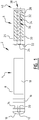
- E-cigarette 2 ( Figure 1 ) comprises battery assembly 4 and atomizer assembly 6.
- atomizer assembly 6 is disposable. It will be understood that the invention can also be applied to systems with other configuration and that the illustrated embodiments is for exemplary purposes only. Details, including connections between components, that are known to the skilled person from conventional E-cigarettes have been omitted from the illustration to reduce the complexity of the drawing.
- Battery assembly 4 comprises housing 8, (LED) indicator 10 with air inlet 12, air flow sensor 14, circuit 16 and battery 18. Air from inlet 12 is provided with air path 20 to sensor 14. Circuit 16 comprises an electronic circuit board that is connected to the relevant components of system 2. Battery 18 can be a rechargeable battery including the required connections to enable recharging. Battery assembly 4 has air inlet 22 and connector 24 to connect battery assembly to atomizer assembly 6.
- Atomizer assembly 6 comprises housing 26 with air path 28 that is surrounded with buffer 30 comprising the E-liquid (for example a mixture of glycerol, propylene glycol, nicotine).
- Buffer material may include wicking material such as silica, cotton, etc.) or buffer 30 can be provided by other buffer means.
- heater element 32 is provided at or around the perimeter of air path 28.
- heater element 32 comprises a wire of metallic titanium core 34 with ceramic titanium oxide layer 36 around metallic core 34.
- the E-liquid is absorbed and/or adsorbed in the porous ceramic layer.
- Wire 32 is heated by passing an electric current through metallic titanium core 34.
- Wire 32 is heated and the E-liquid is evaporated and/or atomized.
- the mixture is provided to outlet 38 of air path 28 at mouth piece 40.
- Heater 32 achieves an improved temperature control and the ability to control the amount of E-liquid evaporating in time by varying the characteristics of the porous ceramic layer 36, such as thickness, size of pores, and porosity.
- heater 28 has its longitudinal axis substantially parallel to air path 28. It will be understood that other configurations are also possible according to the invention.
- heater 28 is surrounded by buffer 30.
- the surface area of buffer 30 is preferably provided with (small) openings that are filled with E-liquid from the buffer. Capillary action transfers liquid from the openings to heater element 30.
- the openings are preferably made in a metal tube-like surface of buffer 30 to prevent burning.
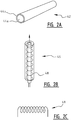
- Heater 42 ( Figure 2A ) comprises a resistance heating material 44a as conductor and porous ceramic layer 44b.
- Heater 46 ( Figure 2B ) is wound as a solenoid 48 ( Figure 2C ) similar to heater 28 as illustrated in Figure 1 .
- heater 50 is configured as a toroid ( Figure 2D ), or flat coil 51 ( Figure 2E ), or flat spiral 52 ( Figure 2F ), for example.
- buffer 30 is provided around air path 28 and heater 32 (see also Figure 2G ).
- liquid reservoir 54 is provided inside the solenoid of heater 56 ( Figure 2H ).
- a further alternative configuration includes heater 58 ( Figure 2I ) wound as toroid structure with liquid passing through the inside of the toroid structure and air flow passing around the toroid structure.
- Another alternative configuration includes heater 60 ( Figure 2J ) formed as a flat coil.
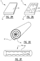
- heater 62 ( Figure 2K ) may comprise a layer of path of resistance heating material 64 as conductor on coated porous ceramic layer 66, or alternatively heater 68 may comprise a conductor layer 70 with coated porous ceramic elements or spots 72 provided thereon ( Figure 2L ).
- heater 74 comprises conductor layer 76 and ceramic layer 78 ( Figure 2M ), and optionally additional ceramic spots 80 ( Figure 2N ).
- Another embodiment comprises porous ceramic layer 82 with conductor 84 wound in a spiral configuration ( Figure 2O ).
- conductor tube 86 with static mixing form 86a coated with ceramic layer 88 ( Figure 2P and 2Q ).
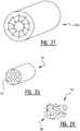
- conductor 90 is a tube ( Figure 2R ) with a ceramic layer 92.
- Tube 90a can be filled with liquid on the inside and having air flow on the outside ( Figure 2S ) or tube 90b has air flow on the inside and liquid buffer on the outside ( Figure 2T ).
- a ceramic layer is provided on the inside and the outside of tube 90.
- tube 90 may comprise a number of smaller tubes or wires 94 with resistance heating material and ceramic material ( Figure 2U ).
- a further alternative configuration ( Figure 2V ) involves resistance heating metallic foam or sponge 96 coated with porous ceramic material 98.
- the disclosed embodiments for heater 32 provide examples of heaters according to the invention that can be applied to systems 2.
- Heater elements according to the invention are preferably manufactured using plasma electrolytic oxidation. As an example, for illustrative reasons only, below some manufacturing methods for some of the possible configurations for the heater element according to the invention will be disclosed.
- a plasma electrolytic chamber 102 ( Figure 3 A)
- Work piece 104 is connected to the anode 106.
- Work piece 104 is clamped/fixed between two screws or clamps 108 that are connected to the ground/earth (anode 104) of a power supply.
- cathode 110 comprises stainless steel honeycomb electrode 112 that, in use, is placed at close distance above work piece 104.
- Electrolyte 114 flows between electrode 112 and anode 106, and effectively flows upwards through honeycomb electrode 112 together with the produced oxygen and hydrogen.
- Electrolyte effluent 116, together with the hydrogen and oxygen, is then cooled and optionally returned to chamber 102.
- the temperature of electrolyte 114 increases from around 11°C entering plasma electrolytic oxidation chamber 102 to 25°C exiting chamber 102 and is then cooled off using a heat exchanger (not shown).
- two power supplies are connected in series: one of 350 Volt and 40 Ampere and a second of 400 Volt and 7 Ampere resulting in a maximum of 750 Volt and 7 Ampere with resulting maximum power of 5.25 kW.
- the power supplies can be connected directly to anode 106 and cathode 110 resulting in direct current (DC) operation of the plasma.
- An optionally added switching circuit provides the option to operate the plasma with DC pulses.
- the frequency of the pulses can be set between DC and 1 kHz and different waveforms can be chosen (block, sine, or triangle).
- Plasma electrolytic oxidation is preferably performed in a pulsed current mode with a frequency (on-off) of about 1000 Hz, preferably with the current set at a fixed value and the voltage increases in time as a result of growing of the porous oxide layer.
- Current between 1 and 7 Ampere can be used to produce a ceramic layer.
- titanium wire 202 ( Figure 3 B) is placed as work piece 104 on top of a titanium plate 204 that is connected to the stainless steel anode.
- the anode is directly connected to wire 202.
- the electrolyte comprised 8 g/l NaSiO3 ⁇ 5H 2 O and 15 g/l (NaPO3) 6 .
- Titanium wire is used made from titanium grade 1, with a diameter of 0.5 mm and 60 cm in length. The wire is coiled and connected to the anode. A potential higher than 500 volts is applied between the anode and cathode resulting in micro arc discharges on the surface of the titanium wire.
- the metallic titanium is oxidized to titanium oxide with addition of silicates and phosphates from the electrolyte.
- the metallic layer is converted to a porous ceramic layer containing titanium oxides, phosphates and silicates. This results in a heater element 302 ( Figure 5 ) according to the invention.
- Current increasing circuit 402 ( Figure 6A ) comprises battery 404, trafo 406, heater element 408 and (super) capacitor 410.
- Other components in circuit 402 include diode 412, resistance 414, switch 416 responding to inhaling, transistor 418. It will be understood that components in circuit 402 can be replaced with other components and/or additional components can be applied.
- alternative circuit 420 ( Figure 6B ) comprises battery 422, heater element 424, capacitor 426, switch 428, resistor 430 and diode 432.
- the heater element When starting to inhale capacitor 410, 426 supplies additional current to heater element 408, 424 to accelerate the temperature increase of heater element 408, 424 and to start atomizing and/or vaporizing almost immediately.
- the heater element is of a titanium material that exhibits a relatively low resistance at room temperature and a higher resistance at an increased temperature thereby enabling a fast response time to the activation signal.
- the conductor of the heater element is made of NiCr and preferably of Titanium.
- E-cigarette 502 ( Figure 8 ) heater 32 is supplied with energy through connector 504 from super capacitor 506.
- Capacitor 506 is charged via external connector 508.
- Capacitor 506 can be charged (semi)-directly and/or indirectly. Such indirect charging can be performed in connection with cigarette box 510 having cigarette storage compartment 512 and battery compartment 514 with battery 516.
- charge connector 518 contacts connector 508 and super capacitor 506 is being charged.
- battery 516 is rechargeable through connector 520.
- the electronic cigarette comprises two main parts, a first part with a battery with an airflow switch and electronic control equipment for the correct operation of an electronic cigarette, and a second part with a cartridge capable of containing the e-liquid, heating element and parts for the transportation of e-liquid onto the heating element.
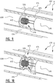
- Cartridge 602 ( Figure 9-10 ) comprises metallic tube 604, in the illustrated embodiments of stainless steel, with eight holes 606 of about 0.25 mm diameter situated about 2.75 mm from the beginning A of the tube that in use is closest to the mouth piece of the electronic cigarette.
- tube 604 is about 29.1 mm in length with an outer diameter of about 4 mm and wall thickness of about 0.3 mm.
- Ceramic tube 608, preferably of zirconium oxide, is provided inside metallic tube 604 at a position about 2.5 mm from openings with a length of about 22 mm, an outer diameter of about 3.4 mm and a wall thickness of about 0.35 mm.
- Ceramic coated titanium heating element 610 is placed in the metallic tube 604 with holes 606.
- Heating element 610 is preferably made of a titanium wire (grade 1) coated with a ceramic layer and wound as a solenoid.
- the diameter of the titanium wire with the ceramic layer is about 0.25 mm
- the total length of the wire used in the heating element is about 90 mm having about ten closely spaced windings 612 with a diameter of about 2.2 mm, and a total length of heating element 610 of about 1.4 mm.
- Heating element 610 is placed inside metallic tube 604 such that the first windings are positioned in ceramic tube 608 preventing heating element 610 to contact metallic tube 604.
- Metallic tube 604 with holes 606 is pressed into a screw cap with connector(s) (not shown) and electrical insulator 618 on side A, and into an end cap (not shown) on the other side.
- Metallic housing 614 preferably a tube of stainless steel, extends between the screw cap and the end cap, with the tube having a length of about 3.8 mm, diameter of about 9.2 mm and wall thickness of about 0.2 mm.
- the space, room or compartment 616 between outer metallic tube 614 and inner metallic tube 604 with holes 606 can be filled with e-liquid.
- the e-liquid comprises about 60% vegetable glycerin, about 30% propylene glycol and about 10% containing nicotine, flavoring and water. The ratio between nicotine, flavoring and water can be adjusted to the preferred amount.
- the screw cap of cartridge 602 is connected to the battery of the electronic cigarette thereby connecting the positive and negative poles of the battery to the positive and negative connector of heating element 610.
- This enables an electric current to flow from the positive pole to the negative pole through the titanium wire to increase the temperature of the titanium wire by joule heating.
- the electric current is controlled by the flow switch that is activated by the user.
- air flows through metallic tube 604 with holes 606 and e-liquid is transported towards heating element 610.
- By increasing the temperature of heating element 610 e-liquid evaporates in the air flow and the evaporated e-liquid is transported to the user.
- cartridge 620 ( Figure 10 ) is provided with similar components with the exception that holes 606 are provided in groove 622.
- cartridges 602, 620 can be combined in further embodiments. Cartridges 602, 620 and alternative embodiments can be used in electronic cigarettes 2, 502 and other embodiments thereof.
- Atomizer assembly 702 ( Figure 11 ) comprises housing 704. At end 706 housing 704 is provided with end ring 708 that is preferably pressed in housing 704, and seal 733. End cap 710 is pressed in ring 708. Housing 704 comprises buffer or reservoir 712 and metal tube 714. Flow path 716 extends through tube 714. Reservoir 712 is positioned around outer surface 718 of tube 714. In the illustrated embodiment inner surface 720 of tube 714 is provided with ceramic layer 722. Tube 714 further comprises heater element 724. Openings 726 in tube 714 enable transport of fluid from reservoir 712 towards heater element 724. In the illustrated embodiment tube 714 has eight openings 726 with a diameter of about 0.2 mm.
- housing 704 is provided with connector 730.
- Connector 730 with opening(s) 731 comprises seal 732 and screw thread 734.
- Edge or stop 736 of connector 730 is used for positioning tube 714.
- stop 736 prevents leakage of liquid from reservoir 712.
- connector 730 is manufactured from brass material.
- connector 730 comprises (separate) connector part 738 having screw thread 734.
- Assembly 702 further comprises ring 740 with opening(s) 741. Rubber ring 742 separates connector 730 from metal pin 744.
- First leg 746 of heater element 724 is connected to pin 744.
- Second leg 748 of heater element 724 is connected to connector 730 and/or ring 740 thereof.
- legs and/or other components can be envisaged in accordance with the present invention, including combining different elements in a single part and/or separating a part into several sub-parts.
- Table 1 Material information Weight (mg) 1 2 3 Before PEO (mg) 525.49 529.82 After PEO (mg) 528.37 539.42 548.71 After heating (mg) 528.09 539.23 547.67 After 5 min in water (mg) 675.7 692.23 705.42 Thickness ( ⁇ m) 36 71 113 Volume geads (ml) 0.15 0.15 0.16 Volume oxide layer (ml) 0.45 0.51 0.59 Porosity (%) 32.71 29.87 26.73 Ceramic wires were manufactured at different process conditions, including with 5 Ampere (wire 1) and 1 Ampere (wire 2) for processing time of an hour. The results are shown in Table 2.
- Table 2 Thickness of ceramic layer porosity and adsorption of two ceramic titanium wires Time + current Ceramic thickness Porosity Adsorption Resistance Wire 1 1 hr @ 5A 55 ⁇ m 45% 21 ⁇ l 1.4 ⁇ Wire 2 1 hr @ 1A 30 ⁇ m 50% 13 ⁇ l 1.3 ⁇
- the experiments illustrate the manufacturing possibilities of the heater element for the system according to the present invention. Further experiments have been conducted to produce other configurations for the heater.
- a metal foil preferably an aluminium foil
- a porous metal (aluminium) oxide layer is provided, preferably in a plasma electrolytic chamber that is described earlier.
- Table 3 shows measured values of plasma electrolytic oxidation with constant current at 5 ampere for 9 minutes. Aluminium foil of 13 ⁇ m thickness was oxidized with a resulting thickness of aluminium oxide of 13 ⁇ m and Table 4 shows the reproducibility of the process.
- Table 5 shows the voltage and current for plasma electrolytic oxidation of aluminium foil at constant current of 2 A. Result was a 13 ⁇ m thick aluminium oxide layer.
- Table 5 Voltage and current of plasma electrolytic oxidation with constant current of 2A. t min. Voltage V Current A 1 380 2 2 415 2 3 429 2 4 437 2 5 443 2 6 448 2 7 452 2
- Table 6 shows the voltage and current of the plasma electrolytic oxidation of aluminium foil with pulsed constant current of 1 kHz at 5 Ampere.
- Table 6 Voltage and current of pulsed constant current of 1 kHz T min. Voltage V Current A 0.167 470 5 0.5 485 5 1 491 5 2 502 5 4 514 5 6 523 5
- plasma electrolytic oxidation was used to provide a porous, flexible and elastic ceramic layer of >70 ⁇ m on titanium foil.
- Plasma electrolytic oxidation grows a titanium oxide layer which is known to be ceramic (TiO 2 ).
- Electrolyte was used with 8 g/l Na 2 SiO 3 ⁇ 5H 2 O (Natrium metasilicate pentahydrate) and 15 g/l (NaPO 3 ) 6 (Natrium hexametaphosphate). The electrolyte is pumped into the reaction chamber to act as the electrolyte and as a coolant.
- Titanium foil was used from titanium grade 2 with a thickness of 124 ⁇ m. In the manufacturing process the voltage increases as a function of time.
- the resulting foil structure can be processed further involving electrochemical machining.
- electrochemical machining ECM
- Titanium grade 2 is locally dissolved in a very controlled manner until the ceramic layer is reached.
- the finished result has to be well defined channels with squared edges and no residue on top of the ceramic layer.
- the ECM process is used with a cathode with the inverse shape of the product placed on top of a Titanium plate that serves as the anode. A potential is placed between the cathode and anode causing the anode to dissolve.
- Electrolyte concentration is 5 M NaNO 3 . Current density can be varied from 20-150 A/cm 2 .
- the heater element is made from a titanium wire, or less preferably from NiCr wire.
- Figure 7 shows the resistance of electric heater elements in relation to temperature for both materials. As mentioned earlier the use of titanium for the heater element is beneficial.
Landscapes
- Chemical & Material Sciences (AREA)
- Engineering & Computer Science (AREA)
- Ceramic Engineering (AREA)
- Resistance Heating (AREA)
- Infusion, Injection, And Reservoir Apparatuses (AREA)
Claims (14)
- Persönliches elektronisches Abgabesystem, das aufweist:- ein Gehäuse (26) mit einem ersten Ende mit einem Einlass (12) und einem zweiten Ende mit einem Auslass (38);- einen Fluidweg (20, 28), der sich im Wesentlichen zwischen dem Einlass (12) und dem Auslass (38) erstreckt;- einen Puffer (30) zum Halten eines Abgabefluids und Verbindungseinrichtungen, die aufgebaut sind, um Abgabefluid an den Fluidweg zu überführen; und- eine Heizung (32), die in, an oder nahe dem Fluidweg (28) bereitgestellt ist, die zum Heizen des Abgabefluids aufgebaut ist, so dass wenigstens ein Teil des Abgabefluids in dem Fluidweg (28) zerstäubt und/oder verdampft, und eine Energiequelle (18), die aufgebaut ist, um Energie an die Heizung (32) bereitzustellen,wobei die Heizung (32) einen Metallleiter (34) aufweist, der mit einer porösen keramischen Schicht (36) versehen ist, die aufgebaut ist, um das Zerstäuben und/oder Verdampfen zu steuern, wobei die keramische Schicht (36) auf oder an dem Leiter (34) mit elektrolytischer Plasmaoxidation bereitgestellt wird, und wobei der Puffer (30) die Heizung (32) im Wesentlichen umgibt, wobei der Puffer (30) mit Öffnungen versehen ist, die zum Überführen von Fluid an die Heizung (32) versehen sind.
- System nach Anspruch 1, wobei die keramische Schicht (36) eine Dicke im Bereich von 5 - 300 m, bevorzugt 10 - 200 m, bevorzugter 50 - 150 m hat und die Dicke am bevorzugtesten etwa 100 m ist.
- System nach einem oder mehreren der vorhergehenden Ansprüche, wobei die Heizung (32) ein Ventilmetall, bevorzugt Titan, aufweist.
- System nach einem oder mehreren der vorhergehenden Ansprüche, wobei der Metallleiter (340), der Heizung einen spiralförmigen Metalldraht aufweist, wobei die spiralförmige Heizung (32) bevorzugt eine Mittelachse hat, die im Wesentlichen in der Längsrichtung des Fluidwegs bereitgestellt ist.
- System nach einem oder mehreren der vorhergehenden Ansprüche, wobei die keramische Schicht (36) mit einer Porigkeit versehen ist, so dass das Abgabefluid durch die keramische Schicht (36) von dem Puffer (30) in die Nachbarschaft des Leiters überführt wird, und wobei die keramische Schicht bevorzugt eine Porigkeit von 10 - 80%, bevorzugter 15 - 50%, sogar noch bevorzugter 20 - 30% hat und die Porigkeit am bevorzugtesten etwa 25% ist.
- System nach einem oder mehreren der vorhergehenden Ansprüche, wobei die Öffnungen aufgebaut sind, um einen Venturi-Effekt zu ermöglichen, der Abgabefluid an die Heizung (32) überführt.
- System nach einem oder mehreren der vorhergehenden Ansprüche, wobei die Öffnungen benachbart zu der Heizung (32) bereitgestellt sind, wobei die Öffnungen bevorzugt in einer Rille bereitgestellt sind.
- System nach einem oder mehreren der vorhergehenden Ansprüche, das ferner eine Leistungs- und/oder Stromerhöhungsschaltung aufweist, die aufgebaut ist, um eine Leistungs- und/oder Stromerhöhung bereitzustellen, wenn die Heizung eingeschaltet wird, wobei die Schaltung bevorzugt einen Superkondensator aufweist, wobei der Superkondensator bevorzugt mit einem Ladeverbinder verbunden ist, der aufgebaut ist, um den Superkondensator mit einer externen Leistungsquelle zum Laden zu verbinden.
- System nach einem oder mehreren der vorhergehenden Ansprüche, wobei das Gehäuse ein Rohr mit einer Innenoberfläche aufweist, die wenigstens teilweise mit einer keramischen Schicht versehen ist, und wobei die Heizung sich wenigstens teilweise in das Rohr erstreckt.
- Zerstäuberanordnung für ein persönliches elektronisches Abgabesystem, die aufweist:- ein Gehäuse mit einem ersten Ende mit einem Einlass und einem zweiten Ende mit einem Auslass;- einen Fluidweg, der sich im Wesentlichen zwischen dem Einlass und dem Auslass erstreckt;- einen Puffer zum Halten eines Abgabefluids und Verbindungseinrichtungen, die aufgebaut sind, um Abgabefluid an den Fluidweg zu überführen; und- eine Heizung, die in, an oder nahe dem Fluidweg bereitgestellt ist, die zum Heizen des Abgabefluids aufgebaut ist, so dass wenigstens ein Teil des Abgabefluids in dem Fluidweg zerstäubt und/oder verdampft,wobei die Heizung einen Leiter und eine poröse keramische Schicht aufweist, die aufgebaut ist, um das Zerstäuben und/oder Verdampfen zu steuern, wobei die keramische Schicht auf oder an dem Leiter mit elektrolytischer Plasmaoxidation bereitgestellt wird.
- Verwendung eines Systems nach einem oder mehreren der Ansprüche 1 - 9 und/oder einer Zerstäuberanordnung nach Anspruch 10 für die Abgabe eines Abgabefluids an eine Person, das die folgenden Schritte aufweist:- Bereitstellen des Systems;- Einatmen an dem zweiten Ende des Gehäuses, um einen subnormalen Druck in dem Fluidweg bereitzustellen, so dass Umgebungsluft in den Einlass gesaugt wird; und Zerstäuben und/oder Verdampfen wenigstens eines Teils des Abgabefluids mit der Heizung und Abgeben an dem Auslass, wobei die Heizung bevorzugt eine Temperatur in dem Bereich von 50 - 300°C, bevorzugter 100 - 200°C und am bevorzugtesten 120 - 180°C erreicht.
- Verfahren zur Herstellung eines persönlichen elektronischen Abgabesystems, das aufweist:- Bereitstellen eines Gehäuses mit einem ersten Ende mit einem Einlass und einem zweiten Ende mit einem Auslass, wobei ein Fluidweg sich im Wesentlichen zwischen dem Einlass und dem Auslass erstreckt;- Bereitstellen eines Puffers zum Halten eines Abgabefluids und Bereitstellen von Verbindungseinrichtungen, die aufgebaut sind, um Abgabefluid an den Fluidweg zu überführen; und- Bereitstellen einer Heizung in, an oder nahe dem Fluidweg zum Heizen des Abgabefluids, so dass wenigstens ein Teil des Abgabefluids in dem Fluidweg zerstäubt und/oder verdampft, und einer Energiequelle zum Bereitstellen von Energie an die Heizung,wobei das Bereitstellen der Heizung das Bereitstellen eines Leiters und einer porösen keramischen Schicht aufweist, die aufgebaut ist, um das Zerstäuben und/oder Verdampfen zu steuern, und die auf oder an dem Leiter mit elektrolytischer Plasmaoxidation bereitgestellt wird.
- Verfahren nach Anspruch 12, das ferner das Bereitstellen einer Energiequelle aufweist, die aufgebaut ist, um Energie an die Heizung bereitzustellen, wobei der Schritt des Bereitstellens der Heizung bevorzugt das Bereitstellen eines Leiters mit einer keramischen Schicht aufweist, und wobei das Bereitstellen der keramischen Schicht bevorzugt elektrolytische Plasmaoxidation und nach dem Bereitstellen der keramischen Schicht auf einer Seite des Leiters bevorzugt das Entfernen wenigstens eines Teils des Leitermaterials unter Verwendung elektrochemischer maschineller Bearbeitung aufweist.
- Verfahren nach einem oder mehreren der Ansprüche 12 oder 13, das ferner den Schritt des Bereitstellens einer Leistungs- und/oder Stromerhöhungsschaltung aufweist, die einen Superkondensator aufweist.
Applications Claiming Priority (9)
| Application Number | Priority Date | Filing Date | Title |
|---|---|---|---|
| NL2014078 | 2014-12-31 | ||
| US201562102862P | 2015-01-13 | 2015-01-13 | |
| NL2014176 | 2015-01-22 | ||
| NL2014461A NL2014461B1 (en) | 2014-12-31 | 2015-03-16 | Personal electronic delivery system and method for delivering a delivery fluid. |
| DE202015006397.7U DE202015006397U1 (de) | 2014-12-31 | 2015-09-11 | Persönliches elektronisches Abgabesystem |
| NL2015766 | 2015-11-10 | ||
| CN201520921474.XU CN205492620U (zh) | 2014-12-31 | 2015-11-18 | 用于对输送流体进行输送的个人电子输送系统 |
| DE202015008791.4U DE202015008791U1 (de) | 2014-12-31 | 2015-12-23 | Persönliches elektronisches Abgabesystem |
| PCT/NL2015/050920 WO2016108694A1 (en) | 2014-12-31 | 2015-12-30 | Personal electronic delivery system, atomizer assembly, use thereof and corresponding production method |
Publications (2)
| Publication Number | Publication Date |
|---|---|
| EP3240445A1 EP3240445A1 (de) | 2017-11-08 |
| EP3240445B1 true EP3240445B1 (de) | 2019-07-03 |
Family
ID=55524423
Family Applications (1)
| Application Number | Title | Priority Date | Filing Date |
|---|---|---|---|
| EP15841120.7A Active EP3240445B1 (de) | 2014-12-31 | 2015-12-30 | Persönliches elektronisches abgabesystem, zerstäuberanordnung, verwendung davon und zugehöriges herstellungsverfahren |
Country Status (4)
| Country | Link |
|---|---|
| US (1) | US10285445B2 (de) |
| EP (1) | EP3240445B1 (de) |
| CN (1) | CN107846972B (de) |
| MX (1) | MX379619B (de) |
Cited By (1)
| Publication number | Priority date | Publication date | Assignee | Title |
|---|---|---|---|---|
| EP4349192A4 (de) * | 2021-06-04 | 2024-11-20 | Shenzhen First Union Technology Co., Ltd. | Aerosolerzeugungsvorrichtung, heizer dafür und herstellungsverfahren |
Families Citing this family (40)
| Publication number | Priority date | Publication date | Assignee | Title |
|---|---|---|---|---|
| WO2015086318A1 (en) | 2013-12-11 | 2015-06-18 | Jt International S.A. | Heating system and method of heating for an inhaler device |
| TWI660685B (zh) | 2014-05-21 | 2019-06-01 | 瑞士商菲利浦莫里斯製品股份有限公司 | 電熱式氣溶膠產生系統及用於此系統中之匣筒 |
| NL2014079B1 (en) * | 2014-12-31 | 2016-10-07 | Metalmembranes Com B V | Heater element, device provided therewith and method for manufacturing such element. |
| US10039324B2 (en) * | 2015-08-14 | 2018-08-07 | Tuanfang Liu | Electronic cigarette |
| NL2016546B1 (en) * | 2016-04-04 | 2017-10-10 | Sluis Cigar Machinery Bv | Electronic cigarette, and method of cleaning an electronic cigarette. |
| US10617151B2 (en) * | 2016-07-21 | 2020-04-14 | Rai Strategic Holdings, Inc. | Aerosol delivery device with a liquid transport element comprising a porous monolith and related method |
| AU2017311493A1 (en) * | 2016-08-12 | 2019-02-28 | Intrepid Brands, LLC | Wickless cartomizer |
| US11903099B2 (en) * | 2016-08-12 | 2024-02-13 | Altria Client Services Llc | Vaporizer of an electronic vaping device and method of forming a vaporizer |
| US9993027B1 (en) | 2016-12-06 | 2018-06-12 | Funai Electric Co., Ltd. | Heater element for a vaporization device |
| US10834967B2 (en) * | 2016-12-27 | 2020-11-17 | Gofire, Inc. | System and method for managing concentrate usage of a user |
| WO2018184787A1 (en) * | 2017-04-05 | 2018-10-11 | Philip Morris Products S.A. | Susceptor for use with an inductively heated aerosol-generating device or system |
| EP3494811B1 (de) * | 2017-12-07 | 2021-03-17 | Fontem Holdings 1 B.V. | Elektronische rauchvorrichtung mit einem heizelement mit modifizierter oberfläche |
| GB201802590D0 (en) | 2018-02-16 | 2018-04-04 | Nicoventures Trading Ltd | Aerosol provision article |
| GB201802591D0 (en) | 2018-02-16 | 2018-04-04 | Nicoventures Trading Ltd | Aerosol provision article |
| GB201805510D0 (en) * | 2018-04-04 | 2018-05-16 | Nicoventures Trading Ltd | Vapour provision systems |
| KR102274250B1 (ko) * | 2018-04-09 | 2021-07-07 | 주식회사 아모센스 | 궐련형 전자담배장치용 발열히터 |
| JP7544603B2 (ja) * | 2018-06-28 | 2024-09-03 | フィリップ・モーリス・プロダクツ・ソシエテ・アノニム | 液体ニコチン製剤を含むニコチン供与源を含有するエアロゾル発生システム用のカートリッジ |
| EP3838034B1 (de) * | 2018-08-13 | 2023-08-09 | Japan Tobacco Inc. | System, verfahren und programm zur aromaerzeugung |
| CN111182807A (zh) * | 2018-08-17 | 2020-05-19 | 深圳雾芯科技有限公司 | 雾化装置及其方法 |
| US11265974B2 (en) * | 2018-08-27 | 2022-03-01 | Rai Strategic Holdings, Inc. | Aerosol delivery device with integrated thermal conductor |
| CN209284320U (zh) * | 2018-10-08 | 2019-08-23 | 深圳麦克韦尔股份有限公司 | 电子烟及其雾化器和发热组件 |
| CN109674092A (zh) * | 2019-01-23 | 2019-04-26 | 深圳麦克韦尔股份有限公司 | 发热丝及电子雾化装置 |
| WO2020200773A1 (en) * | 2019-04-04 | 2020-10-08 | Ventus Medical Limited | A heater assembly |
| CN110292212B (zh) * | 2019-07-08 | 2024-03-29 | 广东金莱特智能科技有限公司 | 电子烟及其气流开关支架、气流开关组件及供电装置 |
| WO2021042201A1 (en) * | 2019-09-05 | 2021-03-11 | Hexo Operations Inc. | Vaporization device with liquid management |
| WO2021122801A1 (en) * | 2019-12-18 | 2021-06-24 | Jt International Sa | Aerosol generation device power system |
| US12279647B2 (en) | 2019-12-23 | 2025-04-22 | Pax Labs, Inc. | Vaporizer cartridge |
| CN113519907A (zh) * | 2020-04-13 | 2021-10-22 | 深圳市合元科技有限公司 | 加热器以及包含该加热器的烟具 |
| US20210401052A1 (en) * | 2020-06-24 | 2021-12-30 | Vuber Technologies, Llc | Vaporization device using frustal porous vaporization media |
| US11839239B2 (en) | 2020-08-12 | 2023-12-12 | DES Products Ltd. | Adjustable airflow cartridge for electronic vaporizer |
| JP7665734B2 (ja) * | 2020-08-19 | 2025-04-21 | 深▲セン▼市新宜康科技股▲分▼有限公司 | 加熱装置、非燃焼加熱デバイス、及び加熱装置ならびに非燃焼加熱デバイスを製造するための方法 |
| EP4233150B1 (de) * | 2020-10-26 | 2024-12-04 | JT International SA | Leistungssystem einer aerosolerzeugungsvorrichtung |
| JP7778138B2 (ja) | 2020-10-26 | 2025-12-01 | ジェイティー インターナショナル エスエイ | エアロゾル発生装置の電力システム |
| CN214629864U (zh) * | 2021-01-27 | 2021-11-09 | 深圳市合元科技有限公司 | 雾化芯组件、雾化器和电子雾化装置 |
| USD1028336S1 (en) | 2021-06-22 | 2024-05-21 | Pax Labs, Inc. | Vaporizer cartridge |
| CN116268599A (zh) * | 2021-12-20 | 2023-06-23 | 深圳麦克韦尔科技有限公司 | 雾化器及雾化装置 |
| CN218008193U (zh) * | 2021-12-31 | 2022-12-13 | 江门摩尔科技有限公司 | 一种电子雾化装置 |
| EP4234126A1 (de) * | 2022-02-23 | 2023-08-30 | ETH Zurich | Metallschäume und verfahren zur produktion davon |
| CN117044993A (zh) * | 2022-05-06 | 2023-11-14 | 深圳麦克韦尔科技有限公司 | 一种多孔生物陶瓷修饰的加热结构及其制备方法和应用 |
| EP4360481A1 (de) * | 2022-10-25 | 2024-05-01 | EQOY International Group AG | Tragbare vorrichtung zur verdampfung einer durch einen benutzer einzuatmenden flüssigkeit |
Family Cites Families (13)
| Publication number | Priority date | Publication date | Assignee | Title |
|---|---|---|---|---|
| US5530225A (en) | 1991-03-11 | 1996-06-25 | Philip Morris Incorporated | Interdigitated cylindrical heater for use in an electrical smoking article |
| US5498855A (en) | 1992-09-11 | 1996-03-12 | Philip Morris Incorporated | Electrically powered ceramic composite heater |
| EP0845220B1 (de) * | 1996-06-17 | 2003-09-03 | Japan Tobacco Inc. | Aromaerzeugender artikel |
| CN201238609Y (zh) * | 2008-07-21 | 2009-05-20 | 北京格林世界科技发展有限公司 | 电子烟用电子雾化器 |
| CN201379072Y (zh) * | 2009-02-11 | 2010-01-13 | 韩力 | 一种改进的雾化电子烟 |
| UA112883C2 (uk) | 2011-12-08 | 2016-11-10 | Філіп Морріс Продактс С.А. | Пристрій для утворення аерозолю з капілярним примежовим шаром |
| US20150164143A1 (en) | 2012-01-25 | 2015-06-18 | Bernard Karel Maas | Electronic Simulated Cigarette and its Vaporizer |
| US8881737B2 (en) * | 2012-09-04 | 2014-11-11 | R.J. Reynolds Tobacco Company | Electronic smoking article comprising one or more microheaters |
| GB2515992A (en) | 2013-03-22 | 2015-01-14 | British American Tobacco Co | Heating smokeable material |
| CN103960782B (zh) * | 2013-09-29 | 2016-09-21 | 深圳麦克韦尔股份有限公司 | 电子烟 |
| CN103720047B (zh) * | 2013-12-13 | 2017-04-05 | 浙江中烟工业有限责任公司 | 一种基于石墨加热的非燃烧吸烟装置 |
| CN103859604B (zh) * | 2014-01-23 | 2017-05-31 | 深圳市康尔科技有限公司 | 电子香烟的发热组件和雾化结构 |
| WO2016108694A1 (en) | 2014-12-31 | 2016-07-07 | UTVG Global IP B.V. | Personal electronic delivery system, atomizer assembly, use thereof and corresponding production method |
-
2015
- 2015-12-30 EP EP15841120.7A patent/EP3240445B1/de active Active
- 2015-12-30 US US15/541,321 patent/US10285445B2/en not_active Expired - Fee Related
- 2015-12-30 MX MX2017008761A patent/MX379619B/es unknown
- 2015-12-30 CN CN201580077238.7A patent/CN107846972B/zh not_active Expired - Fee Related
Non-Patent Citations (1)
| Title |
|---|
| None * |
Cited By (1)
| Publication number | Priority date | Publication date | Assignee | Title |
|---|---|---|---|---|
| EP4349192A4 (de) * | 2021-06-04 | 2024-11-20 | Shenzhen First Union Technology Co., Ltd. | Aerosolerzeugungsvorrichtung, heizer dafür und herstellungsverfahren |
Also Published As
| Publication number | Publication date |
|---|---|
| MX2017008761A (es) | 2018-03-23 |
| EP3240445A1 (de) | 2017-11-08 |
| CN107846972B (zh) | 2020-09-15 |
| MX379619B (es) | 2025-03-11 |
| CN107846972A (zh) | 2018-03-27 |
| US10285445B2 (en) | 2019-05-14 |
| US20170347714A1 (en) | 2017-12-07 |
Similar Documents
| Publication | Publication Date | Title |
|---|---|---|
| US10285445B2 (en) | Personal electronic delivery system, atomizer assembly, use thereof and corresponding production method | |
| WO2016108694A1 (en) | Personal electronic delivery system, atomizer assembly, use thereof and corresponding production method | |
| CN205492620U (zh) | 用于对输送流体进行输送的个人电子输送系统 | |
| WO2016118005A1 (en) | Electronic delivery unit and cartridge, an e-cigarette comprising the unit and cartridge, and method for delivering a delivery fluid | |
| WO2017082728A1 (en) | Cartridge for a personal electronic delivery system, such system, use and method there for | |
| US20180007741A1 (en) | Heater element, device provided therewith and method for manufacturing such element | |
| JP7218253B2 (ja) | 毛細管界面を有するエアロゾル発生装置 | |
| EP3355975B1 (de) | Aerosolbereitstellungssystem | |
| EP3171718B1 (de) | Aerosolbereitstellungssystem | |
| JP2020150958A (ja) | 複数のインダクタコイルを備えたエアロゾル発生システム | |
| CN113891659B (zh) | 具有电导率传感器的气溶胶生成装置和系统 | |
| ES2681951T3 (es) | Cigarrillo electrónico | |
| JP2019520787A (ja) | 電子エアロゾル供給システム及び電子エアロゾル供給システムのための気化器 | |
| JP2019521654A (ja) | 再充填可能なエアロゾル発生物品 | |
| CN113633032A (zh) | 用于气溶胶生成系统的加热器组件 | |
| JP2019527559A (ja) | 電子ベイピング装置の気化器および気化器を形成する方法 | |
| EP3247234B1 (de) | Elektronische freisetzungseinheit und kartusche, e-zigarette mit der einheit und kartusche sowie verfahren zur abgabe einer freisetzungsflüssigkeit | |
| CN114190608A (zh) | 用于气雾生成装置的电阻加热器及气雾生成装置 | |
| NL2014461B1 (en) | Personal electronic delivery system and method for delivering a delivery fluid. | |
| WO2021260153A1 (en) | Apparatus for heating aerosolisable material | |
| NL2014460B1 (en) | Personal electronic delivery unit and cartridge, an e-cigarette comprising the unit and cartridge, and method for delivering a delivery fluid. | |
| EP4444120B1 (de) | Hybrides aerosolerzeugungssystem mit modularem verbrauchsmaterial | |
| EP4266922B1 (de) | Kartusche zur verwendung in einem aerosolerzeugungssystem | |
| HK1231701B (en) | Aerosol provision system | |
| HK1231701A1 (en) | Aerosol provision system |
Legal Events
| Date | Code | Title | Description |
|---|---|---|---|
| STAA | Information on the status of an ep patent application or granted ep patent |
Free format text: STATUS: THE INTERNATIONAL PUBLICATION HAS BEEN MADE |
|
| PUAI | Public reference made under article 153(3) epc to a published international application that has entered the european phase |
Free format text: ORIGINAL CODE: 0009012 |
|
| STAA | Information on the status of an ep patent application or granted ep patent |
Free format text: STATUS: REQUEST FOR EXAMINATION WAS MADE |
|
| 17P | Request for examination filed |
Effective date: 20170731 |
|
| AK | Designated contracting states |
Kind code of ref document: A1 Designated state(s): AL AT BE BG CH CY CZ DE DK EE ES FI FR GB GR HR HU IE IS IT LI LT LU LV MC MK MT NL NO PL PT RO RS SE SI SK SM TR |
|
| AX | Request for extension of the european patent |
Extension state: BA ME |
|
| DAV | Request for validation of the european patent (deleted) | ||
| DAX | Request for extension of the european patent (deleted) | ||
| GRAP | Despatch of communication of intention to grant a patent |
Free format text: ORIGINAL CODE: EPIDOSNIGR1 |
|
| STAA | Information on the status of an ep patent application or granted ep patent |
Free format text: STATUS: GRANT OF PATENT IS INTENDED |
|
| INTG | Intention to grant announced |
Effective date: 20180822 |
|
| GRAJ | Information related to disapproval of communication of intention to grant by the applicant or resumption of examination proceedings by the epo deleted |
Free format text: ORIGINAL CODE: EPIDOSDIGR1 |
|
| STAA | Information on the status of an ep patent application or granted ep patent |
Free format text: STATUS: REQUEST FOR EXAMINATION WAS MADE |
|
| GRAP | Despatch of communication of intention to grant a patent |
Free format text: ORIGINAL CODE: EPIDOSNIGR1 |
|
| STAA | Information on the status of an ep patent application or granted ep patent |
Free format text: STATUS: GRANT OF PATENT IS INTENDED |
|
| INTC | Intention to grant announced (deleted) | ||
| INTG | Intention to grant announced |
Effective date: 20190116 |
|
| GRAS | Grant fee paid |
Free format text: ORIGINAL CODE: EPIDOSNIGR3 |
|
| GRAA | (expected) grant |
Free format text: ORIGINAL CODE: 0009210 |
|
| STAA | Information on the status of an ep patent application or granted ep patent |
Free format text: STATUS: THE PATENT HAS BEEN GRANTED |
|
| AK | Designated contracting states |
Kind code of ref document: B1 Designated state(s): AL AT BE BG CH CY CZ DE DK EE ES FI FR GB GR HR HU IE IS IT LI LT LU LV MC MK MT NL NO PL PT RO RS SE SI SK SM TR |
|
| REG | Reference to a national code |
Ref country code: GB Ref legal event code: FG4D |
|
| REG | Reference to a national code |
Ref country code: CH Ref legal event code: EP Ref country code: AT Ref legal event code: REF Ref document number: 1149900 Country of ref document: AT Kind code of ref document: T Effective date: 20190715 |
|
| REG | Reference to a national code |
Ref country code: IE Ref legal event code: FG4D |
|
| REG | Reference to a national code |
Ref country code: DE Ref legal event code: R096 Ref document number: 602015033297 Country of ref document: DE |
|
| REG | Reference to a national code |
Ref country code: CH Ref legal event code: NV Representative=s name: ARNOLD AND SIEDSMA AG, CH |
|
| REG | Reference to a national code |
Ref country code: NL Ref legal event code: FP |
|
| REG | Reference to a national code |
Ref country code: LT Ref legal event code: MG4D |
|
| REG | Reference to a national code |
Ref country code: AT Ref legal event code: MK05 Ref document number: 1149900 Country of ref document: AT Kind code of ref document: T Effective date: 20190703 |
|
| PG25 | Lapsed in a contracting state [announced via postgrant information from national office to epo] |
Ref country code: CZ Free format text: LAPSE BECAUSE OF FAILURE TO SUBMIT A TRANSLATION OF THE DESCRIPTION OR TO PAY THE FEE WITHIN THE PRESCRIBED TIME-LIMIT Effective date: 20190703 Ref country code: HR Free format text: LAPSE BECAUSE OF FAILURE TO SUBMIT A TRANSLATION OF THE DESCRIPTION OR TO PAY THE FEE WITHIN THE PRESCRIBED TIME-LIMIT Effective date: 20190703 Ref country code: LT Free format text: LAPSE BECAUSE OF FAILURE TO SUBMIT A TRANSLATION OF THE DESCRIPTION OR TO PAY THE FEE WITHIN THE PRESCRIBED TIME-LIMIT Effective date: 20190703 Ref country code: SE Free format text: LAPSE BECAUSE OF FAILURE TO SUBMIT A TRANSLATION OF THE DESCRIPTION OR TO PAY THE FEE WITHIN THE PRESCRIBED TIME-LIMIT Effective date: 20190703 Ref country code: BG Free format text: LAPSE BECAUSE OF FAILURE TO SUBMIT A TRANSLATION OF THE DESCRIPTION OR TO PAY THE FEE WITHIN THE PRESCRIBED TIME-LIMIT Effective date: 20191003 Ref country code: PT Free format text: LAPSE BECAUSE OF FAILURE TO SUBMIT A TRANSLATION OF THE DESCRIPTION OR TO PAY THE FEE WITHIN THE PRESCRIBED TIME-LIMIT Effective date: 20191104 Ref country code: NO Free format text: LAPSE BECAUSE OF FAILURE TO SUBMIT A TRANSLATION OF THE DESCRIPTION OR TO PAY THE FEE WITHIN THE PRESCRIBED TIME-LIMIT Effective date: 20191003 Ref country code: FI Free format text: LAPSE BECAUSE OF FAILURE TO SUBMIT A TRANSLATION OF THE DESCRIPTION OR TO PAY THE FEE WITHIN THE PRESCRIBED TIME-LIMIT Effective date: 20190703 Ref country code: AT Free format text: LAPSE BECAUSE OF FAILURE TO SUBMIT A TRANSLATION OF THE DESCRIPTION OR TO PAY THE FEE WITHIN THE PRESCRIBED TIME-LIMIT Effective date: 20190703 |
|
| PG25 | Lapsed in a contracting state [announced via postgrant information from national office to epo] |
Ref country code: ES Free format text: LAPSE BECAUSE OF FAILURE TO SUBMIT A TRANSLATION OF THE DESCRIPTION OR TO PAY THE FEE WITHIN THE PRESCRIBED TIME-LIMIT Effective date: 20190703 Ref country code: IS Free format text: LAPSE BECAUSE OF FAILURE TO SUBMIT A TRANSLATION OF THE DESCRIPTION OR TO PAY THE FEE WITHIN THE PRESCRIBED TIME-LIMIT Effective date: 20191103 Ref country code: RS Free format text: LAPSE BECAUSE OF FAILURE TO SUBMIT A TRANSLATION OF THE DESCRIPTION OR TO PAY THE FEE WITHIN THE PRESCRIBED TIME-LIMIT Effective date: 20190703 Ref country code: LV Free format text: LAPSE BECAUSE OF FAILURE TO SUBMIT A TRANSLATION OF THE DESCRIPTION OR TO PAY THE FEE WITHIN THE PRESCRIBED TIME-LIMIT Effective date: 20190703 Ref country code: AL Free format text: LAPSE BECAUSE OF FAILURE TO SUBMIT A TRANSLATION OF THE DESCRIPTION OR TO PAY THE FEE WITHIN THE PRESCRIBED TIME-LIMIT Effective date: 20190703 Ref country code: GR Free format text: LAPSE BECAUSE OF FAILURE TO SUBMIT A TRANSLATION OF THE DESCRIPTION OR TO PAY THE FEE WITHIN THE PRESCRIBED TIME-LIMIT Effective date: 20191004 |
|
| PG25 | Lapsed in a contracting state [announced via postgrant information from national office to epo] |
Ref country code: TR Free format text: LAPSE BECAUSE OF FAILURE TO SUBMIT A TRANSLATION OF THE DESCRIPTION OR TO PAY THE FEE WITHIN THE PRESCRIBED TIME-LIMIT Effective date: 20190703 |
|
| PG25 | Lapsed in a contracting state [announced via postgrant information from national office to epo] |
Ref country code: RO Free format text: LAPSE BECAUSE OF FAILURE TO SUBMIT A TRANSLATION OF THE DESCRIPTION OR TO PAY THE FEE WITHIN THE PRESCRIBED TIME-LIMIT Effective date: 20190703 Ref country code: IT Free format text: LAPSE BECAUSE OF FAILURE TO SUBMIT A TRANSLATION OF THE DESCRIPTION OR TO PAY THE FEE WITHIN THE PRESCRIBED TIME-LIMIT Effective date: 20190703 Ref country code: EE Free format text: LAPSE BECAUSE OF FAILURE TO SUBMIT A TRANSLATION OF THE DESCRIPTION OR TO PAY THE FEE WITHIN THE PRESCRIBED TIME-LIMIT Effective date: 20190703 Ref country code: PL Free format text: LAPSE BECAUSE OF FAILURE TO SUBMIT A TRANSLATION OF THE DESCRIPTION OR TO PAY THE FEE WITHIN THE PRESCRIBED TIME-LIMIT Effective date: 20190703 Ref country code: DK Free format text: LAPSE BECAUSE OF FAILURE TO SUBMIT A TRANSLATION OF THE DESCRIPTION OR TO PAY THE FEE WITHIN THE PRESCRIBED TIME-LIMIT Effective date: 20190703 |
|
| PG25 | Lapsed in a contracting state [announced via postgrant information from national office to epo] |
Ref country code: SK Free format text: LAPSE BECAUSE OF FAILURE TO SUBMIT A TRANSLATION OF THE DESCRIPTION OR TO PAY THE FEE WITHIN THE PRESCRIBED TIME-LIMIT Effective date: 20190703 Ref country code: SM Free format text: LAPSE BECAUSE OF FAILURE TO SUBMIT A TRANSLATION OF THE DESCRIPTION OR TO PAY THE FEE WITHIN THE PRESCRIBED TIME-LIMIT Effective date: 20190703 Ref country code: IS Free format text: LAPSE BECAUSE OF FAILURE TO SUBMIT A TRANSLATION OF THE DESCRIPTION OR TO PAY THE FEE WITHIN THE PRESCRIBED TIME-LIMIT Effective date: 20200224 |
|
| REG | Reference to a national code |
Ref country code: DE Ref legal event code: R097 Ref document number: 602015033297 Country of ref document: DE |
|
| PLBE | No opposition filed within time limit |
Free format text: ORIGINAL CODE: 0009261 |
|
| STAA | Information on the status of an ep patent application or granted ep patent |
Free format text: STATUS: NO OPPOSITION FILED WITHIN TIME LIMIT |
|
| PG2D | Information on lapse in contracting state deleted |
Ref country code: IS |
|
| 26N | No opposition filed |
Effective date: 20200603 |
|
| PG25 | Lapsed in a contracting state [announced via postgrant information from national office to epo] |
Ref country code: MC Free format text: LAPSE BECAUSE OF FAILURE TO SUBMIT A TRANSLATION OF THE DESCRIPTION OR TO PAY THE FEE WITHIN THE PRESCRIBED TIME-LIMIT Effective date: 20190703 Ref country code: SI Free format text: LAPSE BECAUSE OF FAILURE TO SUBMIT A TRANSLATION OF THE DESCRIPTION OR TO PAY THE FEE WITHIN THE PRESCRIBED TIME-LIMIT Effective date: 20190703 |
|
| PG25 | Lapsed in a contracting state [announced via postgrant information from national office to epo] |
Ref country code: IE Free format text: LAPSE BECAUSE OF NON-PAYMENT OF DUE FEES Effective date: 20191230 |
|
| PG25 | Lapsed in a contracting state [announced via postgrant information from national office to epo] |
Ref country code: CY Free format text: LAPSE BECAUSE OF FAILURE TO SUBMIT A TRANSLATION OF THE DESCRIPTION OR TO PAY THE FEE WITHIN THE PRESCRIBED TIME-LIMIT Effective date: 20190703 |
|
| PG25 | Lapsed in a contracting state [announced via postgrant information from national office to epo] |
Ref country code: MT Free format text: LAPSE BECAUSE OF FAILURE TO SUBMIT A TRANSLATION OF THE DESCRIPTION OR TO PAY THE FEE WITHIN THE PRESCRIBED TIME-LIMIT Effective date: 20190703 Ref country code: HU Free format text: LAPSE BECAUSE OF FAILURE TO SUBMIT A TRANSLATION OF THE DESCRIPTION OR TO PAY THE FEE WITHIN THE PRESCRIBED TIME-LIMIT; INVALID AB INITIO Effective date: 20151230 |
|
| PG25 | Lapsed in a contracting state [announced via postgrant information from national office to epo] |
Ref country code: MK Free format text: LAPSE BECAUSE OF FAILURE TO SUBMIT A TRANSLATION OF THE DESCRIPTION OR TO PAY THE FEE WITHIN THE PRESCRIBED TIME-LIMIT Effective date: 20190703 |
|
| PGFP | Annual fee paid to national office [announced via postgrant information from national office to epo] |
Ref country code: NL Payment date: 20220531 Year of fee payment: 7 Ref country code: LU Payment date: 20220527 Year of fee payment: 7 Ref country code: GB Payment date: 20220527 Year of fee payment: 7 Ref country code: FR Payment date: 20220525 Year of fee payment: 7 Ref country code: DE Payment date: 20220527 Year of fee payment: 7 |
|
| PGFP | Annual fee paid to national office [announced via postgrant information from national office to epo] |
Ref country code: BE Payment date: 20220527 Year of fee payment: 7 |
|
| PGFP | Annual fee paid to national office [announced via postgrant information from national office to epo] |
Ref country code: CH Payment date: 20230109 Year of fee payment: 8 |
|
| REG | Reference to a national code |
Ref country code: DE Ref legal event code: R119 Ref document number: 602015033297 Country of ref document: DE |
|
| REG | Reference to a national code |
Ref country code: NL Ref legal event code: MM Effective date: 20230101 |
|
| GBPC | Gb: european patent ceased through non-payment of renewal fee |
Effective date: 20221230 |
|
| REG | Reference to a national code |
Ref country code: BE Ref legal event code: MM Effective date: 20221231 |
|
| PG25 | Lapsed in a contracting state [announced via postgrant information from national office to epo] |
Ref country code: LU Free format text: LAPSE BECAUSE OF NON-PAYMENT OF DUE FEES Effective date: 20221230 |
|
| PG25 | Lapsed in a contracting state [announced via postgrant information from national office to epo] |
Ref country code: NL Free format text: LAPSE BECAUSE OF NON-PAYMENT OF DUE FEES Effective date: 20230101 |
|
| PG25 | Lapsed in a contracting state [announced via postgrant information from national office to epo] |
Ref country code: GB Free format text: LAPSE BECAUSE OF NON-PAYMENT OF DUE FEES Effective date: 20221230 Ref country code: DE Free format text: LAPSE BECAUSE OF NON-PAYMENT OF DUE FEES Effective date: 20230701 |
|
| PG25 | Lapsed in a contracting state [announced via postgrant information from national office to epo] |
Ref country code: FR Free format text: LAPSE BECAUSE OF NON-PAYMENT OF DUE FEES Effective date: 20221231 Ref country code: BE Free format text: LAPSE BECAUSE OF NON-PAYMENT OF DUE FEES Effective date: 20221231 |
|
| REG | Reference to a national code |
Ref country code: CH Ref legal event code: PL |
|
| PG25 | Lapsed in a contracting state [announced via postgrant information from national office to epo] |
Ref country code: CH Free format text: LAPSE BECAUSE OF NON-PAYMENT OF DUE FEES Effective date: 20231231 |
|
| PG25 | Lapsed in a contracting state [announced via postgrant information from national office to epo] |
Ref country code: CH Free format text: LAPSE BECAUSE OF NON-PAYMENT OF DUE FEES Effective date: 20231231 |