EP3240741B1 - Système de stockage et de récupération robotique - Google Patents
Système de stockage et de récupération robotique Download PDFInfo
- Publication number
- EP3240741B1 EP3240741B1 EP15876140.3A EP15876140A EP3240741B1 EP 3240741 B1 EP3240741 B1 EP 3240741B1 EP 15876140 A EP15876140 A EP 15876140A EP 3240741 B1 EP3240741 B1 EP 3240741B1
- Authority
- EP
- European Patent Office
- Prior art keywords
- retriever
- robotic
- storage
- container
- retrieval system
- Prior art date
- Legal status (The legal status is an assumption and is not a legal conclusion. Google has not performed a legal analysis and makes no representation as to the accuracy of the status listed.)
- Active
Links
Images


Classifications
-
- B—PERFORMING OPERATIONS; TRANSPORTING
- B65—CONVEYING; PACKING; STORING; HANDLING THIN OR FILAMENTARY MATERIAL
- B65G—TRANSPORT OR STORAGE DEVICES, e.g. CONVEYORS FOR LOADING OR TIPPING, SHOP CONVEYOR SYSTEMS OR PNEUMATIC TUBE CONVEYORS
- B65G1/00—Storing articles, individually or in orderly arrangement, in warehouses or magazines
- B65G1/02—Storage devices
- B65G1/04—Storage devices mechanical
- B65G1/0492—Storage devices mechanical with cars adapted to travel in storage aisles
-
- B—PERFORMING OPERATIONS; TRANSPORTING
- B65—CONVEYING; PACKING; STORING; HANDLING THIN OR FILAMENTARY MATERIAL
- B65G—TRANSPORT OR STORAGE DEVICES, e.g. CONVEYORS FOR LOADING OR TIPPING, SHOP CONVEYOR SYSTEMS OR PNEUMATIC TUBE CONVEYORS
- B65G1/00—Storing articles, individually or in orderly arrangement, in warehouses or magazines
- B65G1/02—Storage devices
- B65G1/04—Storage devices mechanical
Definitions
- the present disclosure relates to robotic systems and devices, and particularly to systems for storing and retrieving items.
- the present invention relates to a robotic storage and retrieval system according to the preamble of claim 1 and to a method for robotic storage and retrieval of a container to and from a shelving unit according to the preamble of claim 13.
- a robotic storage and retrieval system and such a robotic storage and retrieval method are known from the document US 2012/0027546 A1 .
- a retriever with a cavity for receiving a container is known from US 7 381 022 B1 .
- a robotic storage and retrieval system comprises a shelving unit including at least one vertical column of a plurality of vertically arranged storage locations, each storage location sized to receive a container, a unique identifier associated with each of the plurality of storage locations, and a pair of vertical rails associated with each of the at least one vertical column.
- the system further comprises a robotic retriever defining a cavity sized to receive the container.
- the robotic retriever includes a drive mechanism for propelling the retriever to a position adjacent a lowermost one of the storage locations of the shelving unit, a recognition unit configured to recognize the unique identifier of each of the plurality of storage locations, and a traction drive mechanism adapted to engage the pair of vertical rails to propel the retriever vertically along the at least one vertical column.
- the robotic retriever includes a retriever apparatus operable to engage a container to move the container between a storage location and the cavity of the robotic retriever, and a processor operable to execute instructions to control the drive mechanism and traction drive mechanism to drive the retriever to a storage location according to the unique identifier as recognized by the recognition unit, and to operate the retriever apparatus to move a container between the storage location and the cavity of the robotic retriever.
- the robotic storage system according to the invention is defined in claim 1 whereas the method for robotic storage and retrieval of a container, according to the invention, is defined in claim 13.
- the present disclosure contemplates a robotic system that automatically stores and retrieves containers from a shelving unit.
- the robotic system includes a robotic retriever 10 shown in FIG. 1 that has a body 12 with a pair of drive wheels 20 and a pair of steerable wheels 22 .
- the retriever 10 includes a drive motor (not shown) operable to rotate the drive wheels and a steering mechanism (not shown) operable to pivot the steerable wheels 22 .
- the drive motor and steering mechanism can be of known configurations particularly useful for propelling robotic devices.
- the body 12 may house a power supply (not shown), such as a rechargeable battery, as well as control electronics for the drive motor and steering mechanism.
- the control electronics may incorporate a processor capable of executing control instructions of a software program stored in a memory associated with the processor or in a remote central memory.
- the control electronics may further include wireless capabilities, with at least wireless receiving capabilities for receiving instructions from a remote controller, such as the hand-held controller 150 depicted in FIG. 4 .
- the control electronics, processor and software program may be of known configuration and functionality that is particularly useful for controlling the movement of robotic devices.
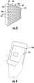
- the power supply, electronics and processor may be embedded within the body 12 or contained within a housing mounted to the body 12 in a conventional manner, such as the self-contained power and electronics component 19 shown in FIG. 2 .
- the electronics and processor may incorporate input and output elements 19a , such as for connecting the power supply to an external power outlet, or such as a conventional USB port for interfacing with an external device or with a USB memory device.
- the component 19 may also incorporate wireless technology to permit wireless communication with an external device, such as a phone or computer.
- the body 12 of the robotic retriever 10 includes opposite side walls 13 , a top wall 14 , a front wall 16 , a back wall 17 and a bottom wall 18 that together define a cavity 15 ( FIG. 1 ) that is sized to contain a payload, such as a container 130 ( FIGS. 3 , 6 ) to be stored in a shelving unit 100 as illustrated in FIG. 3 .
- the size of the body and cavity are based on the size of the payload being stored and retrieved.
- the payload may be a container 130 that is the size of a standard banker's box or of a standard four-drawer cabinet.
- the robotic retriever 10 and particularly the drive system are configured to meet the weight and size demands of the payload.
- the robotic retriever is configured to carry a payload of up to 20 kg (45 lbs).
- the robotic retriever may incorporate a recognition component 40 in the top wall 14 of the body 12 , as shown in FIG. 2 .
- the recognition component 40 is adapted to recognize an identifier 135 associated with a container 130 ( FIG. 3 ) being retrieved.
- the identifier 135 may be a bar code or similar coded identifier, in which case the recognition component 40 is a bar code reader.
- the identifier may be an RF tag with a unique identification that can be read by a known RF reader, in which case the recognition component 40 is an RF reader.
- the recognition component 40 may be a camera with associated image recognition software capable of comparing the captured image with a data base of stored images. The recognition component 40 is thus operable to generate information fed to an on-board processor, such as the processor in the component 19 , or to remote processor to determine the identity of the container in a known manner.
- the robotic retriever 10 is configured to store and retrieve containers from a shelving unit 100 as shown in FIG. 3 .
- the shelving unit includes at least one column of vertically arranged storage locations, and in particular an array of vertical rails 110, 112 and storage locations in the form of horizontal shelves 115 sized according to the size of container 130 being stored and according to the available space for the shelving unit.
- the present disclosure contemplates a shelving unit capable of storing containers from floor to ceiling to make optimum use of the available space.
- the shelving unit can be about eight feet tall, with the width and number of vertical columns of containers determined by the available space along a wall.
- the shelving unit 100 includes six columns of six rows of shelves sized to support container dimensions of 30 - 35 cm by 30 - 35 cm (12 - 14 inches by 12 - 14 inches).
- Each container within the shelving unit includes a unique identifier 135 as described above.
- each individual storage space may include the unique identifier rather than the container, or each identifier 135 may include data pertaining to both the container and the storage space.
- the object of the unique identifier is to provide means for locating a particular container or payload in the shelving unit 100 . Whether the identification 135 is associated with the container or with the location in the shelving unit, or both, determines how the container is located and retrieved as well as how the location of the container is documented.
- Software within the processor in component 19 is adapted to the particular identification approach adopted for the shelving unit 100 .
- the containers are stored vertically and horizontally within the shelving unit.
- the robotic retriever 10 is configured to travel to any shelf within the unit 100 to store or retrieve a container 130 .
- the robotic retriever 10 is wheeled to allow the retriever to be maneuvered to a location in front of the vertical column of the desired location.
- the retriever 10 includes traction wheels 30 adjacent the drive wheels 20 ( FIG. 1 ) that can be driven by the same drive mechanism as the drive wheels.
- the traction wheels and drive wheels share a common axle.
- Each traction wheel is configured to engage a vertical rail 110 , 112 , and particularly a traction surface 113 of the rail, as depicted in FIG. 5 .
- the traction wheels 30 and traction surface 113 can incorporate splines, in the form of a rack and pinion gear arrangement.
- the traction wheel and surface are configured so that rotation of the traction wheel propels the robotic retriever along the rail.
- Other traction configurations are contemplated, such as a high friction surface on either or both of the traction wheel and traction surface.
- the robotic retriever 10 is supported on the shelving unit 100 with the front wall 16 of the retriever body 12 against the shelving unit and the cavity 15 facing the unit.
- the retriever thus includes a gripper apparatus 35 that is configured to grip the vertical side rails 110, 112 to help hold the front wall 16 of the retriever against the shelving unit.
- the drive wheels 20 may also help hold the retriever against the side rails, as illustrated in FIG. 5 .
- the side rails are configured to cooperate with the gripper apparatus 35 to hold the robotic retriever against the rails as the retriever travels vertically upward.
- the side rails 110 may be in the form of a T-shaped body defining an interior ledge 114 against which rollers 37 of the gripper apparatus may bear.
- the side rail 112 at the side of the shelving unit 100 does not require a T-shape but can instead be an L-shape to still define an interior ledge for the rollers 37 .
- the rollers 37 are mounted on the end of an extendable arm 36 that is housed within a channel 13a in the side wall 13 of the retriever body 12 .
- the extendable arms 36 are provided with an extension mechanism such as a motor and rack/pinion arrangement between the motor and the top or bottom edge of the arm. Other mechanisms may be provided for selectively extending the arms 36 when it is desired for the robotic retriever to climb the side rails of the shelving unit.
- the extendable arms 36 may be configured to navigate past the ledge 114 of the side rail so that the rollers 37 may engage the inside of the ledge, as shown in FIG.
- gripper apparatus may be provided that are capable of engaging the side rails to prevent the retriever 10 from falling from the shelving unit as the retriever is propelled upward by the traction wheels 30 .
- the gripper apparatus may be configured to use magnetic attraction to keep the retriever in proper position against the shelving unit.
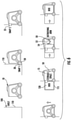
- FIG. 6 A sequence of operation of the robotic retriever according to one aspect of the present disclosure is depicted in FIG. 6 .
- the retriever 10 travels to the shelving unit 100 and moves into alignment with the side rails of a desired column of shelves.
- the retriever may rely on the recognition component 40 to determine the proper column based on the desired shelf location.
- This desired location may be a next available empty shelf for storing a container 130 or may be the shelf containing a particular desired container.
- the recognition component and associated software may be configured to follow a particular protocol for locating the desired shelf position.
- the robotic retriever may not rely on a recognition component but may instead execute software capable of recognizing location by movements alone.
- the software operates from a stored "map" of locations and determines the necessary movements, including distance and direction of travel both along the floor and along the side rails, from a current location to a desired location.
- the software may permit manually guidance of the retriever 10 by the user.
- the robotic retriever 10 is propelled forward until the front wall 16 is adjacent to or abuts the shelving unit.
- the gripper apparatus 35 is actuated in the third step to firmly engage the vertical rails 110, 112 and in the next step the traction wheels are actuated to drive the retriever up the rails.
- the robotic retriever has climbed to the shelf supporting the desired container 130 the cavity 15 is aligned to receive the container.
- the robotic retriever includes a retriever apparatus 50 mounted at the back wall 17 of the retriever ( FIG. 1 ) that is adapted to engage the container 130 .
- the retriever apparatus 50 includes an extension mechanism 52 and a grabber 54 that is configured to engage the container.
- the container 130 and grabber 54 are mutually configured to achieve solid engagement of the container by the retriever apparatus to be able to pull the container back into the cavity 15 of the robotic retriever 10 .
- the engagement mechanism may be a latch/receiver arrangement or a magnetic component. Since the retriever apparatus 50 only needs to slide the container along the shelf and cavity the engagement mechanism can be simplified. Once the grabber 54 engages the container, the extension mechanism 52 reverses to pull the container back into the cavity 15 . It can be understood that the retriever apparatus is operable to push a container from the cavity into a shelf location by extending the extension mechanism 52 when a container is within the cavity.
- the traction wheels are reversed to drive the robotic retriever down the side rails until the wheels 20 , 22 contact the floor.
- Sensors may be incorporated into the robotic retriever to determine whether the retriever is back on the floor. Sensors may also be incorporated within the cavity to verify that the container is properly positioned within either the cavity 15 (for retrieval) or within the shelving unit 100 (for storage) before the retriever is activated.
- the control system may direct the retriever to a desired location away from the shelving unit where the user can remove the container that has been retrieved. If the retriever is operating in a storage mode, the retriever may be directed to an idle location, which may include a docking station where an on-board battery may be recharged and the retriever may be stored.
- the robotic retriever may be part of a complete storage and retrieval system that integrates with a user-operated controller.
- a hand-held controller 150 FIG. 4
- the hand-held controller may include a key pad or touch screen 151 for entering instructions and information.
- the hand-held controller may thus allow the user to identify a specific shelf for storing or retrieving a container, or may allow the user to enter a particular identification number for a container to be retrieved.
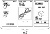
- the hand-held controller may be a smart phone and the instructions may implemented using an app. Screen shots for an exemplary app for use with a smart-phone are shown in FIG. 7 .
- a PC-based software program may be provided for controlling the robotic retriever.
- control and operation of the robotic retriever may rely on a data base to store information regarding shelf location and container identification.
- the data base may also be permitted to store user comments associated with a particular container, such as an inventory of contents.
- the software associated with storage and retrieval system may incorporate a searchable data base that allows the user to search based on contents of the containers so that the user does not need to know where a particular item is stored. For example, the user desiring to retrieve a photo album from storage may enter commands to search the data base the container holding a photo album.
- the system extracts the container identification and/or its shelf location and directs the robotic retriever to execute a retrieval operation as described above.
- the data base for the storage and retrieval system may retain historical records regarding each container and/or its contents.
Landscapes
- Engineering & Computer Science (AREA)
- Mechanical Engineering (AREA)
- Warehouses Or Storage Devices (AREA)
Claims (14)
- Système robotique de stockage et de récupération comprenant:une unité d'étagères (100) ayant:au moins une colonne verticale d'un ensemble d'emplacements de stockage disposés verticalement, chaque emplacement de stockage étant dimensionné pour recevoir un conteneur (130),une paire de rails verticaux (110, 112) associés à chacune des colonnes verticales, etun dispositif robotique de récupération (10) comprenant:un mécanisme d'entraînement avec des roues motrices (20) pour propulser le dispositif de récupération (10) dans une position adjacente à l'emplacement le plus bas des emplacements de stockage de l'unité d'étagères (100),une unité de reconnaissance configurée pour reconnaître l'unique identifiant (135) de chaque emplacement de l'ensemble des emplacements de stockage,un mécanisme d'entraînement en traction pour coopérer avec la paire de rails verticaux (110, 112) et propulser le dispositif de récupération (10) verticalement le long d'au moins une colonne verticale,un appareil de récupération (50) pour coopérer avec le conteneur (130) et déplacer le conteneur (130) entre une position de stockage et la cavité (15) du dispositif robotique de récupération (10), etun processeur fonctionnant de manière à exécuter les instructions pour commander le mécanisme d'entraînement et le mécanisme d'entraînement en traction pour entraîner le dispositif récupérateur (10) à l'emplacement de stockage correspondant à l'identifiant unique (135) qui a été reconnu par l'unité de reconnaissance et faire fonctionner l'appareil de récupération (50) pour déplacer le conteneur (130) entre la position de stockage et la cavité du dispositif robotique de récupération (10),système caractérisé en ce quel'unité d'étagères (100) comprend un identifiant unique (135) associé à chaque position de l'ensemble des positions de stockage,le dispositif robotique de récupération (10) définit une cavité (15) dimensionnée pour recevoir le conteneur (130), etle dispositif de récupération (10) comprend des roues de traction (30) adjacentes aux roues d'entraînement (20) qui peuvent être entraînées par le même mécanisme d'entraînement que les roues d'entraînement, les roues de traction (30) et les roues d'entraînement (20) partageant un axe commun.
- Système robotique de stockage et de récupération selon la revendication 1, dans lequel la paire de rails verticaux (110, 112) et le mécanisme d'entraînement en traction comprennent un montage à crémaillère et pignons, le mécanisme d'entraînement en traction ayant une paire de roues de traction (30) sous la forme de pignons et la paire de rails verticaux (110, 112) est configurée sous la forme de pignons à crémaillère.
- Système robotique de stockage et de récupération selon la revendication 1, comprenant en outre: un appareil d'accrochage (35) entre l'unité d'étagères (100) et le dispositif robotique de récupération (10) fonctionnant pour maintenir le dispositif récupérateur (10) engagé avec la paire de rails latéraux (110, 112) lorsque le dispositif récupérateur est propulsé verticalement le long des rails latéraux (110, 112).
- Système robotique de stockage et de récupération selon la revendication 3, dans lequel l'appareil d'accrochage (35) comprend une paire de bras (36) qui se déploient du dispositif robotique de récupération (10), chaque bras (36) ayant un galet (37) pour coopérer avec l'un des rails latéraux (110, 112) correspondants de l'unité d'étagères (100).
- Système robotique de stockage et de récupération selon la revendication 1, dans lequel
l'identifiant unique (135) est un identifiant parmi les suivants: code barre, étiquette RFID ou image unique, et l'unité de reconnaissance est une unité parmi les suivantes: lecteur de code à barres, lecteur d'étiquette RFID et caméra associée à un programme de reconnaissance d'images. - Système robotique de stockage et de récupération selon la revendication 1, dans lequel le mécanisme d'entraînement comprend un ensemble de roues de contact avec le sol, fonctionnant pour guider le dispositif robotique de récupération (10) entre l'unité d'étagères (100) et un emplacement libre, séparé.
- Système robotique de stockage et de récupération selon la revendication 1, dans lequel le dispositif robotique de récupération (10) comprend une alimentation embarquée pour fournir la puissance au mécanisme d'entraînement, à l'unité de reconnaissance, au mécanisme d'entraînement en traction et à l'appareil récupérateur (50).
- Système robotique de stockage et de récupération selon la revendication 1, dans lequel l'appareil récupérateur (50) comprend un mécanisme déployable (52) monté sur la paroi arrière (17) du dispositif robotique de récupération (10) dans la cavité (15) et un grappin (54) à l'extrémité déployable du mécanisme déployable (52), le grappin (54) étant configuré pour coopérer avec un conteneur (130).
- Système robotique de stockage et de récupération selon la revendication 8, dans lequel le grappin (54) comprend un composant magnétique ou un composant à verrouillage configuré pour coopérer avec un organe récepteur correspondant, du conteneur (130).
- Système robotique de stockage et de récupération selon la revendication 1, dans lequel l'unité d'étagères (100) comprend un ensemble de colonnes verticales parmi un ensemble d'emplacements de stockage organisés verticalement.
- Système robotique de stockage et de récupération selon la revendication 1, dans lequel le processeur comprend un composant de communication sans fil et fonctionnant pour communiquer sans fil avec un dispositif éloigné.
- Système robotique de stockage et de récupération selon la revendication 11, dans lequel le dispositif éloigné est un smartphone.
- Procédé pour le stockage et la récupération robotisée d'un conteneur (130) par rapport à une unité d'étagères (100) ayant un ensemble de colonnes verticales pour un ensemble d'emplacements de stockage verticaux, consistant à:identifier un emplacement de stockage souhaité,diriger un dispositif robotique de récupération (10) sur une colonne verticale correspondante dans laquelle se trouve l'emplacement de stockage voulu, le dispositif de récupération (10) étant propulsé par un mécanisme d'entraînement comprenant des roues motrices (20),faire coopérer le dispositif robotique de récupération (10) avec une paire de rails verticaux (110, 112) de la colonne verticale correspondante,propulser le dispositif robotique de récupération (10) verticalement le long de la paire de rails verticaux (110, 112) jusqu'à ce que le dispositif robotique de récupération (10) se trouve à l'emplacement de stockage voulu, et
déplacer le conteneur (130) entre le dispositif robotique de récupération (10) et l'emplacement de stockage voulu avec un appareil récupérateur du dispositif robotique de récupération (10),procédé caractérisé en ce quel'unité d'étagères (100) comprend un identifiant unique (135) associé à chacun des emplacements de l'ensemble d'emplacements de stockage,le conteneur est reçu dans une cavité (15) définie par le dispositif robotique de récupération (10), etle dispositif robotique de récupération (10) comprend des unités de traction (30) adjacentes aux roues motrices (20) qui peuvent être entraînées par le même mécanisme d'entraînement que les roues motrices, les roues de traction (30) et les roues motrices (20) partageant un axe commun. - Procédé de stockage et de récupération robotisé d'un conteneur selon la revendication 13, procédé selon lequel le dispositif robotique de récupération (10) est organisé pour assurer la fonction de stockage et de récupération en utilisant un smartphone.
Applications Claiming Priority (2)
| Application Number | Priority Date | Filing Date | Title |
|---|---|---|---|
| US201462097407P | 2014-12-29 | 2014-12-29 | |
| PCT/US2015/067812 WO2016109498A1 (fr) | 2014-12-29 | 2015-12-29 | Système de stockage et de récupération robotique |
Publications (3)
| Publication Number | Publication Date |
|---|---|
| EP3240741A1 EP3240741A1 (fr) | 2017-11-08 |
| EP3240741A4 EP3240741A4 (fr) | 2018-08-29 |
| EP3240741B1 true EP3240741B1 (fr) | 2022-02-09 |
Family
ID=56284984
Family Applications (1)
| Application Number | Title | Priority Date | Filing Date |
|---|---|---|---|
| EP15876140.3A Active EP3240741B1 (fr) | 2014-12-29 | 2015-12-29 | Système de stockage et de récupération robotique |
Country Status (2)
| Country | Link |
|---|---|
| EP (1) | EP3240741B1 (fr) |
| WO (1) | WO2016109498A1 (fr) |
Families Citing this family (3)
| Publication number | Priority date | Publication date | Assignee | Title |
|---|---|---|---|---|
| CN108100547B (zh) * | 2017-04-24 | 2020-07-24 | 郭氢 | 可用于邮件、包裹和单件物品的自动化存取货仓库保管系统 |
| JP7065287B2 (ja) * | 2018-06-22 | 2022-05-12 | パナソニックIpマネジメント株式会社 | 移動装置、搬送装置、移動システム、及び移動方法 |
| CN110654673B (zh) * | 2019-09-24 | 2021-03-19 | 丁江 | 一种适用于智能搬运的物流货架 |
Family Cites Families (7)
| Publication number | Priority date | Publication date | Assignee | Title |
|---|---|---|---|---|
| US6262863B1 (en) * | 1998-07-01 | 2001-07-17 | Storage Technology Corporation | Automated storage library with rail mechanism providing flexible robot access |
| US6438448B1 (en) * | 2000-02-08 | 2002-08-20 | Storage Technology Corporation | Self aligning robotic arm calibration apparatus |
| US7381022B1 (en) * | 2004-12-18 | 2008-06-03 | Rodney Joe King | Automated 3-dimensional multitasking, stocking, storage, and distribution system |
| HU229022B1 (hu) * | 2009-03-02 | 2013-07-29 | Antal Zombori | Tárolóberendezés raktározáshoz |
| US9321591B2 (en) * | 2009-04-10 | 2016-04-26 | Symbotic, LLC | Autonomous transports for storage and retrieval systems |
| US20110229296A1 (en) * | 2010-03-20 | 2011-09-22 | Van Ooyen Wes | Apparatus, system and method for storage and dispensing of items |
| WO2012016031A1 (fr) * | 2010-07-28 | 2012-02-02 | Par Systems, Inc. | Systèmes de stockage et de récupération robotiques |
-
2015
- 2015-12-29 EP EP15876140.3A patent/EP3240741B1/fr active Active
- 2015-12-29 WO PCT/US2015/067812 patent/WO2016109498A1/fr not_active Ceased
Also Published As
| Publication number | Publication date |
|---|---|
| WO2016109498A1 (fr) | 2016-07-07 |
| EP3240741A1 (fr) | 2017-11-08 |
| EP3240741A4 (fr) | 2018-08-29 |
Similar Documents
| Publication | Publication Date | Title |
|---|---|---|
| US20200207250A1 (en) | Automated Loading of Delivery Vehicles Using Automated Guided Vehicles | |
| CN111727158B (zh) | 用于物件取放和运输的室内自动机器人系统 | |
| US9875503B2 (en) | Method and apparatus for transporting a plurality of stacked motorized transport units | |
| US9558472B1 (en) | Inventory facility | |
| US10962963B2 (en) | Robot to pick up and transport objects and method using such a robot | |
| US20180099846A1 (en) | Method and apparatus for transporting a plurality of stacked motorized transport units | |
| US10669069B2 (en) | Storage totes | |
| CN114026516A (zh) | 自主实用小车及机器人小车平台 | |
| CA3066266A1 (fr) | Preparation automatisee de livraisons dans des vehicules de livraison a l`aide de vehicules a guidage automatique | |
| EP3386900B1 (fr) | Installation d'inventaire comprenant des bacs de stockage en tissu | |
| CN115443247A (zh) | 物料搬运车辆以及包括移动存储推车、运输工具和物料搬运车辆的货物存储和取回系统 | |
| EP3240741B1 (fr) | Système de stockage et de récupération robotique | |
| US20190220032A1 (en) | Autonomous delivery system with autonomous delivery vehicles and dedicated delivery receiving stations | |
| JP2018517646A5 (fr) | ||
| US10119272B1 (en) | Interference frames | |
| KR20220143129A (ko) | 토트 전달 구역, 자재 취급 차량, 운송기를 포함하는 다중 레벨 창고 랙 시스템을 포함하는 시스템, 및 그 사용 방법 | |
| CN114906042B (zh) | 搁架和包括其的递送车辆 | |
| CN119768749A (zh) | 自主实用小车及机器人小车平台 | |
| US20250091502A1 (en) | Delivery robot | |
| US20250091223A1 (en) | Delivery robot | |
| US20250092729A1 (en) | Delivery robot | |
| KR101300164B1 (ko) | 카트 무인 자동 수거 시스템 | |
| KR20250040409A (ko) | 배송로봇 | |
| CN210776798U (zh) | 一种智能流转库房管理系统 | |
| JP2024510722A (ja) | 床領域上の格納装置を取り扱う移動式格納システム |
Legal Events
| Date | Code | Title | Description |
|---|---|---|---|
| STAA | Information on the status of an ep patent application or granted ep patent |
Free format text: STATUS: THE INTERNATIONAL PUBLICATION HAS BEEN MADE |
|
| PUAI | Public reference made under article 153(3) epc to a published international application that has entered the european phase |
Free format text: ORIGINAL CODE: 0009012 |
|
| STAA | Information on the status of an ep patent application or granted ep patent |
Free format text: STATUS: REQUEST FOR EXAMINATION WAS MADE |
|
| 17P | Request for examination filed |
Effective date: 20170731 |
|
| AK | Designated contracting states |
Kind code of ref document: A1 Designated state(s): AL AT BE BG CH CY CZ DE DK EE ES FI FR GB GR HR HU IE IS IT LI LT LU LV MC MK MT NL NO PL PT RO RS SE SI SK SM TR |
|
| AX | Request for extension of the european patent |
Extension state: BA ME |
|
| DAV | Request for validation of the european patent (deleted) | ||
| DAX | Request for extension of the european patent (deleted) | ||
| A4 | Supplementary search report drawn up and despatched |
Effective date: 20180730 |
|
| RIC1 | Information provided on ipc code assigned before grant |
Ipc: B25J 19/00 20060101ALI20180724BHEP Ipc: G06K 7/10 20060101ALI20180724BHEP Ipc: B65G 1/06 20060101ALI20180724BHEP Ipc: B65G 1/04 20060101AFI20180724BHEP Ipc: B25J 11/00 20060101ALI20180724BHEP Ipc: F16H 19/04 20060101ALI20180724BHEP Ipc: G06K 7/14 20060101ALI20180724BHEP Ipc: G06K 19/06 20060101ALI20180724BHEP Ipc: G06K 19/07 20060101ALI20180724BHEP Ipc: B25J 5/00 20060101ALI20180724BHEP |
|
| RAP1 | Party data changed (applicant data changed or rights of an application transferred) |
Owner name: ROBERT BOSCH GMBH |
|
| GRAP | Despatch of communication of intention to grant a patent |
Free format text: ORIGINAL CODE: EPIDOSNIGR1 |
|
| STAA | Information on the status of an ep patent application or granted ep patent |
Free format text: STATUS: GRANT OF PATENT IS INTENDED |
|
| INTG | Intention to grant announced |
Effective date: 20210715 |
|
| GRAJ | Information related to disapproval of communication of intention to grant by the applicant or resumption of examination proceedings by the epo deleted |
Free format text: ORIGINAL CODE: EPIDOSDIGR1 |
|
| STAA | Information on the status of an ep patent application or granted ep patent |
Free format text: STATUS: REQUEST FOR EXAMINATION WAS MADE |
|
| GRAP | Despatch of communication of intention to grant a patent |
Free format text: ORIGINAL CODE: EPIDOSNIGR1 |
|
| STAA | Information on the status of an ep patent application or granted ep patent |
Free format text: STATUS: GRANT OF PATENT IS INTENDED |
|
| INTC | Intention to grant announced (deleted) | ||
| INTG | Intention to grant announced |
Effective date: 20211201 |
|
| GRAS | Grant fee paid |
Free format text: ORIGINAL CODE: EPIDOSNIGR3 |
|
| GRAA | (expected) grant |
Free format text: ORIGINAL CODE: 0009210 |
|
| STAA | Information on the status of an ep patent application or granted ep patent |
Free format text: STATUS: THE PATENT HAS BEEN GRANTED |
|
| AK | Designated contracting states |
Kind code of ref document: B1 Designated state(s): AL AT BE BG CH CY CZ DE DK EE ES FI FR GB GR HR HU IE IS IT LI LT LU LV MC MK MT NL NO PL PT RO RS SE SI SK SM TR |
|
| REG | Reference to a national code |
Ref country code: GB Ref legal event code: FG4D |
|
| REG | Reference to a national code |
Ref country code: CH Ref legal event code: EP Ref country code: AT Ref legal event code: REF Ref document number: 1467396 Country of ref document: AT Kind code of ref document: T Effective date: 20220215 |
|
| REG | Reference to a national code |
Ref country code: DE Ref legal event code: R096 Ref document number: 602015076882 Country of ref document: DE |
|
| REG | Reference to a national code |
Ref country code: IE Ref legal event code: FG4D |
|
| REG | Reference to a national code |
Ref country code: LT Ref legal event code: MG9D |
|
| REG | Reference to a national code |
Ref country code: NL Ref legal event code: MP Effective date: 20220209 |
|
| REG | Reference to a national code |
Ref country code: AT Ref legal event code: MK05 Ref document number: 1467396 Country of ref document: AT Kind code of ref document: T Effective date: 20220209 |
|
| PG25 | Lapsed in a contracting state [announced via postgrant information from national office to epo] |
Ref country code: SE Free format text: LAPSE BECAUSE OF FAILURE TO SUBMIT A TRANSLATION OF THE DESCRIPTION OR TO PAY THE FEE WITHIN THE PRESCRIBED TIME-LIMIT Effective date: 20220209 Ref country code: RS Free format text: LAPSE BECAUSE OF FAILURE TO SUBMIT A TRANSLATION OF THE DESCRIPTION OR TO PAY THE FEE WITHIN THE PRESCRIBED TIME-LIMIT Effective date: 20220209 Ref country code: PT Free format text: LAPSE BECAUSE OF FAILURE TO SUBMIT A TRANSLATION OF THE DESCRIPTION OR TO PAY THE FEE WITHIN THE PRESCRIBED TIME-LIMIT Effective date: 20220609 Ref country code: NO Free format text: LAPSE BECAUSE OF FAILURE TO SUBMIT A TRANSLATION OF THE DESCRIPTION OR TO PAY THE FEE WITHIN THE PRESCRIBED TIME-LIMIT Effective date: 20220509 Ref country code: NL Free format text: LAPSE BECAUSE OF FAILURE TO SUBMIT A TRANSLATION OF THE DESCRIPTION OR TO PAY THE FEE WITHIN THE PRESCRIBED TIME-LIMIT Effective date: 20220209 Ref country code: LT Free format text: LAPSE BECAUSE OF FAILURE TO SUBMIT A TRANSLATION OF THE DESCRIPTION OR TO PAY THE FEE WITHIN THE PRESCRIBED TIME-LIMIT Effective date: 20220209 Ref country code: HR Free format text: LAPSE BECAUSE OF FAILURE TO SUBMIT A TRANSLATION OF THE DESCRIPTION OR TO PAY THE FEE WITHIN THE PRESCRIBED TIME-LIMIT Effective date: 20220209 Ref country code: ES Free format text: LAPSE BECAUSE OF FAILURE TO SUBMIT A TRANSLATION OF THE DESCRIPTION OR TO PAY THE FEE WITHIN THE PRESCRIBED TIME-LIMIT Effective date: 20220209 Ref country code: BG Free format text: LAPSE BECAUSE OF FAILURE TO SUBMIT A TRANSLATION OF THE DESCRIPTION OR TO PAY THE FEE WITHIN THE PRESCRIBED TIME-LIMIT Effective date: 20220509 |
|
| PG25 | Lapsed in a contracting state [announced via postgrant information from national office to epo] |
Ref country code: PL Free format text: LAPSE BECAUSE OF FAILURE TO SUBMIT A TRANSLATION OF THE DESCRIPTION OR TO PAY THE FEE WITHIN THE PRESCRIBED TIME-LIMIT Effective date: 20220209 Ref country code: LV Free format text: LAPSE BECAUSE OF FAILURE TO SUBMIT A TRANSLATION OF THE DESCRIPTION OR TO PAY THE FEE WITHIN THE PRESCRIBED TIME-LIMIT Effective date: 20220209 Ref country code: GR Free format text: LAPSE BECAUSE OF FAILURE TO SUBMIT A TRANSLATION OF THE DESCRIPTION OR TO PAY THE FEE WITHIN THE PRESCRIBED TIME-LIMIT Effective date: 20220510 Ref country code: FI Free format text: LAPSE BECAUSE OF FAILURE TO SUBMIT A TRANSLATION OF THE DESCRIPTION OR TO PAY THE FEE WITHIN THE PRESCRIBED TIME-LIMIT Effective date: 20220209 Ref country code: AT Free format text: LAPSE BECAUSE OF FAILURE TO SUBMIT A TRANSLATION OF THE DESCRIPTION OR TO PAY THE FEE WITHIN THE PRESCRIBED TIME-LIMIT Effective date: 20220209 |
|
| PG25 | Lapsed in a contracting state [announced via postgrant information from national office to epo] |
Ref country code: IS Free format text: LAPSE BECAUSE OF FAILURE TO SUBMIT A TRANSLATION OF THE DESCRIPTION OR TO PAY THE FEE WITHIN THE PRESCRIBED TIME-LIMIT Effective date: 20220609 |
|
| PG25 | Lapsed in a contracting state [announced via postgrant information from national office to epo] |
Ref country code: SM Free format text: LAPSE BECAUSE OF FAILURE TO SUBMIT A TRANSLATION OF THE DESCRIPTION OR TO PAY THE FEE WITHIN THE PRESCRIBED TIME-LIMIT Effective date: 20220209 Ref country code: SK Free format text: LAPSE BECAUSE OF FAILURE TO SUBMIT A TRANSLATION OF THE DESCRIPTION OR TO PAY THE FEE WITHIN THE PRESCRIBED TIME-LIMIT Effective date: 20220209 Ref country code: RO Free format text: LAPSE BECAUSE OF FAILURE TO SUBMIT A TRANSLATION OF THE DESCRIPTION OR TO PAY THE FEE WITHIN THE PRESCRIBED TIME-LIMIT Effective date: 20220209 Ref country code: EE Free format text: LAPSE BECAUSE OF FAILURE TO SUBMIT A TRANSLATION OF THE DESCRIPTION OR TO PAY THE FEE WITHIN THE PRESCRIBED TIME-LIMIT Effective date: 20220209 Ref country code: DK Free format text: LAPSE BECAUSE OF FAILURE TO SUBMIT A TRANSLATION OF THE DESCRIPTION OR TO PAY THE FEE WITHIN THE PRESCRIBED TIME-LIMIT Effective date: 20220209 Ref country code: CZ Free format text: LAPSE BECAUSE OF FAILURE TO SUBMIT A TRANSLATION OF THE DESCRIPTION OR TO PAY THE FEE WITHIN THE PRESCRIBED TIME-LIMIT Effective date: 20220209 |
|
| REG | Reference to a national code |
Ref country code: DE Ref legal event code: R097 Ref document number: 602015076882 Country of ref document: DE |
|
| PG25 | Lapsed in a contracting state [announced via postgrant information from national office to epo] |
Ref country code: AL Free format text: LAPSE BECAUSE OF FAILURE TO SUBMIT A TRANSLATION OF THE DESCRIPTION OR TO PAY THE FEE WITHIN THE PRESCRIBED TIME-LIMIT Effective date: 20220209 |
|
| PLBE | No opposition filed within time limit |
Free format text: ORIGINAL CODE: 0009261 |
|
| STAA | Information on the status of an ep patent application or granted ep patent |
Free format text: STATUS: NO OPPOSITION FILED WITHIN TIME LIMIT |
|
| 26N | No opposition filed |
Effective date: 20221110 |
|
| PG25 | Lapsed in a contracting state [announced via postgrant information from national office to epo] |
Ref country code: SI Free format text: LAPSE BECAUSE OF FAILURE TO SUBMIT A TRANSLATION OF THE DESCRIPTION OR TO PAY THE FEE WITHIN THE PRESCRIBED TIME-LIMIT Effective date: 20220209 |
|
| PG25 | Lapsed in a contracting state [announced via postgrant information from national office to epo] |
Ref country code: IT Free format text: LAPSE BECAUSE OF FAILURE TO SUBMIT A TRANSLATION OF THE DESCRIPTION OR TO PAY THE FEE WITHIN THE PRESCRIBED TIME-LIMIT Effective date: 20220209 |
|
| REG | Reference to a national code |
Ref country code: CH Ref legal event code: PL |
|
| REG | Reference to a national code |
Ref country code: BE Ref legal event code: MM Effective date: 20221231 |
|
| PG25 | Lapsed in a contracting state [announced via postgrant information from national office to epo] |
Ref country code: LU Free format text: LAPSE BECAUSE OF NON-PAYMENT OF DUE FEES Effective date: 20221229 |
|
| PG25 | Lapsed in a contracting state [announced via postgrant information from national office to epo] |
Ref country code: LI Free format text: LAPSE BECAUSE OF NON-PAYMENT OF DUE FEES Effective date: 20221231 Ref country code: IE Free format text: LAPSE BECAUSE OF NON-PAYMENT OF DUE FEES Effective date: 20221229 Ref country code: CH Free format text: LAPSE BECAUSE OF NON-PAYMENT OF DUE FEES Effective date: 20221231 |
|
| PG25 | Lapsed in a contracting state [announced via postgrant information from national office to epo] |
Ref country code: BE Free format text: LAPSE BECAUSE OF NON-PAYMENT OF DUE FEES Effective date: 20221231 |
|
| PG25 | Lapsed in a contracting state [announced via postgrant information from national office to epo] |
Ref country code: HU Free format text: LAPSE BECAUSE OF FAILURE TO SUBMIT A TRANSLATION OF THE DESCRIPTION OR TO PAY THE FEE WITHIN THE PRESCRIBED TIME-LIMIT; INVALID AB INITIO Effective date: 20151229 |
|
| PG25 | Lapsed in a contracting state [announced via postgrant information from national office to epo] |
Ref country code: CY Free format text: LAPSE BECAUSE OF FAILURE TO SUBMIT A TRANSLATION OF THE DESCRIPTION OR TO PAY THE FEE WITHIN THE PRESCRIBED TIME-LIMIT Effective date: 20220209 |
|
| PGFP | Annual fee paid to national office [announced via postgrant information from national office to epo] |
Ref country code: DE Payment date: 20240227 Year of fee payment: 9 |
|
| PG25 | Lapsed in a contracting state [announced via postgrant information from national office to epo] |
Ref country code: MK Free format text: LAPSE BECAUSE OF FAILURE TO SUBMIT A TRANSLATION OF THE DESCRIPTION OR TO PAY THE FEE WITHIN THE PRESCRIBED TIME-LIMIT Effective date: 20220209 |
|
| PG25 | Lapsed in a contracting state [announced via postgrant information from national office to epo] |
Ref country code: MC Free format text: LAPSE BECAUSE OF FAILURE TO SUBMIT A TRANSLATION OF THE DESCRIPTION OR TO PAY THE FEE WITHIN THE PRESCRIBED TIME-LIMIT Effective date: 20220209 |
|
| PG25 | Lapsed in a contracting state [announced via postgrant information from national office to epo] |
Ref country code: MC Free format text: LAPSE BECAUSE OF FAILURE TO SUBMIT A TRANSLATION OF THE DESCRIPTION OR TO PAY THE FEE WITHIN THE PRESCRIBED TIME-LIMIT Effective date: 20220209 |
|
| PG25 | Lapsed in a contracting state [announced via postgrant information from national office to epo] |
Ref country code: MT Free format text: LAPSE BECAUSE OF FAILURE TO SUBMIT A TRANSLATION OF THE DESCRIPTION OR TO PAY THE FEE WITHIN THE PRESCRIBED TIME-LIMIT Effective date: 20220209 |
|
| PGFP | Annual fee paid to national office [announced via postgrant information from national office to epo] |
Ref country code: GB Payment date: 20241218 Year of fee payment: 10 |
|
| PGFP | Annual fee paid to national office [announced via postgrant information from national office to epo] |
Ref country code: FR Payment date: 20241219 Year of fee payment: 10 |
|
| REG | Reference to a national code |
Ref country code: DE Ref legal event code: R119 Ref document number: 602015076882 Country of ref document: DE |
|
| PG25 | Lapsed in a contracting state [announced via postgrant information from national office to epo] |
Ref country code: DE Free format text: LAPSE BECAUSE OF NON-PAYMENT OF DUE FEES Effective date: 20250701 |
|
| PG25 | Lapsed in a contracting state [announced via postgrant information from national office to epo] |
Ref country code: TR Free format text: LAPSE BECAUSE OF FAILURE TO SUBMIT A TRANSLATION OF THE DESCRIPTION OR TO PAY THE FEE WITHIN THE PRESCRIBED TIME-LIMIT Effective date: 20220209 |