EP3240965B1 - Eckventil - Google Patents
Eckventil Download PDFInfo
- Publication number
- EP3240965B1 EP3240965B1 EP16805341.1A EP16805341A EP3240965B1 EP 3240965 B1 EP3240965 B1 EP 3240965B1 EP 16805341 A EP16805341 A EP 16805341A EP 3240965 B1 EP3240965 B1 EP 3240965B1
- Authority
- EP
- European Patent Office
- Prior art keywords
- valve
- angle
- spindle
- thread
- securing ring
- Prior art date
- Legal status (The legal status is an assumption and is not a legal conclusion. Google has not performed a legal analysis and makes no representation as to the accuracy of the status listed.)
- Not-in-force
Links
- 229920003023 plastic Polymers 0.000 claims description 23
- 239000004033 plastic Substances 0.000 claims description 23
- 238000007789 sealing Methods 0.000 claims description 5
- 239000002184 metal Substances 0.000 description 5
- 230000000694 effects Effects 0.000 description 4
- 239000000463 material Substances 0.000 description 4
- 238000009434 installation Methods 0.000 description 3
- 238000004519 manufacturing process Methods 0.000 description 3
- XLYOFNOQVPJJNP-UHFFFAOYSA-N water Substances O XLYOFNOQVPJJNP-UHFFFAOYSA-N 0.000 description 3
- 238000011161 development Methods 0.000 description 2
- 230000018109 developmental process Effects 0.000 description 2
- 229910001369 Brass Inorganic materials 0.000 description 1
- 229920000914 Metallic fiber Polymers 0.000 description 1
- 230000015572 biosynthetic process Effects 0.000 description 1
- 239000010951 brass Substances 0.000 description 1
- 230000003247 decreasing effect Effects 0.000 description 1
- 230000002045 lasting effect Effects 0.000 description 1
- 230000007774 longterm Effects 0.000 description 1
- 238000012986 modification Methods 0.000 description 1
- 230000004048 modification Effects 0.000 description 1
- 230000001105 regulatory effect Effects 0.000 description 1
- 230000002787 reinforcement Effects 0.000 description 1
- 230000007704 transition Effects 0.000 description 1
Images


Classifications
-
- F—MECHANICAL ENGINEERING; LIGHTING; HEATING; WEAPONS; BLASTING
- F16—ENGINEERING ELEMENTS AND UNITS; GENERAL MEASURES FOR PRODUCING AND MAINTAINING EFFECTIVE FUNCTIONING OF MACHINES OR INSTALLATIONS; THERMAL INSULATION IN GENERAL
- F16K—VALVES; TAPS; COCKS; ACTUATING-FLOATS; DEVICES FOR VENTING OR AERATING
- F16K1/00—Lift valves or globe valves, i.e. cut-off apparatus with closure members having at least a component of their opening and closing motion perpendicular to the closing faces
- F16K1/02—Lift valves or globe valves, i.e. cut-off apparatus with closure members having at least a component of their opening and closing motion perpendicular to the closing faces with screw-spindle
- F16K1/04—Lift valves or globe valves, i.e. cut-off apparatus with closure members having at least a component of their opening and closing motion perpendicular to the closing faces with screw-spindle with a cut-off member rigid with the spindle, e.g. main valves
Definitions
- the invention relates to an angle valve for connecting sanitary fittings with a housing, comprising an inlet nozzle and an outlet nozzle, between which a valve seat is formed, which corresponds to the sealing surface of a valve stem, wherein the valve stem is made of plastic and having a thread having a Thread cooperates in the housing, and a retaining ring to secure the valve stem against unscrewing.
- the connection of wash or sink fittings is usually carried out with the help of angle valves (see, for example, Schell corner regulating valve "Comfort" Order No. 049160699).
- the angle valves have an inlet connection for connection to the wall connection fitting of the sanitary installation of the building, an outlet connection for connecting the outlet fitting and a shut-off valve.
- Such an angle valve is, for example, from the DE 297 05 205 U1 known.
- the provided in the angle valves valve spindle for shutting off or adjusting the water flow to the connected valve is usually made of brass.
- the valve spindles can be actuated by means of a handle. To operate the spindles these are provided with a metric fine thread, which corresponds to a provided in the housing of the angle valve metallic thread.
- valve stem must be secured against unscrewing from the housing in accordance with DIN 3227. This is usually done by a round wire ring made of metal, which is arranged in an annular groove in the valve housing. When the valve is fully open, the thread of the valve spindle is pressed against the circlip, preventing the spindle from unscrewing.
- angle valves are also known, which, among other things, are completely or partially made of plastic for hygienic reasons (cf., for example, US Pat. AU 491 845 B2 ). For angle valves with a plastic spindle requires the long - term behavior of Plastics a reinforcement in the spindle thread.
- the metric fine thread used in the metal corner valves described above due to the decreasing plastic strength over other thread forms, does not have a sufficient shear surface to ensure lasting tightness at the pressures occurring in the water pipes of the building installation. Due to the thread geometry, in particular with respect to the slope and the flank height, with plastic trapezoidal threads a Auswindsch by means of round wire ring, as used in the above-described angle valves made of metal, unsuitable. The point load at the end of the trapezoidal thread would result in the use of round wire rings as a fuse to flow of the plastic and thus damage to the thread. The function of the corner valve made of plastic would therefore no longer be ensured.
- the invention aims to remedy this situation.
- the invention is based on the object to provide an angle valve, in which a Ausfsch is created for a plastic spindle, which ensures the reliability of the angle valve even at high system pressures.
- this object is achieved in that the retaining ring has an inner cone which corresponds to a cone of the valve stem.
- an angle valve is provided in which a reliable function is ensured even at high system pressures within the building installation lines and at the same time provides a reliable backup against unscrewing the spindle made of plastic. This is ensured by the fact that due to the corresponding cones of the securing ring on the one hand and the valve spindle on the other hand, with increasing pressure on the spindle, the cones wedged together, whereby an additional clamping force is caused. Thus, an increase in the clamping force against unscrewing is caused by increasing the pressure on the spindle.
- the retaining ring is located in an annular groove of the housing and is supported by a stop surface against a shoulder of the housing.
- the retaining ring is made of plastic.
- the production of the locking ring made of plastic is attractive on the one hand from a cost point of view, on the other hand, this provides a very good combination of materials between the plastic spindle and the retaining ring.
- the retaining ring is formed by a disc and a shoulder. This is a structurally simple design that is simple and therefore inexpensive to produce.
- the retaining ring on cutouts which are formed in the disc, and cutouts which are formed in the shoulder, wherein the cutouts are arranged in alternation on the retaining ring.
- the retaining ring on a slot.
- the retaining ring is divided, so that there is also the possibility to easily mount the retaining ring in the angle valve.
- the retaining ring presses together in the region of the gap, so that the retaining ring can pass the inlet and can enter the annular groove, in which he then relaxes again.
- the thread of the valve stem is a trapezoidal thread.
- the formation of the thread as a trapezoidal thread has been found to be particularly suitable when using valve spindles made of plastic, because the trapezoidal thread has a relatively high load capacity.
- the corner valve chosen as an exemplary embodiment has a housing 1.
- the housing 1 is usually made of metal. However, it can also be made of plastic. It comprises an inlet connection 11 and an outlet connection 13 as well as a valve connection 26, inlet connection 11 and valve connection 26 being coaxial with one another, the outlet connection 13 being aligned at right angles thereto.
- a valve stem 3 is arranged, which is secured with a retaining ring 4, 104 in the valve stub 26 and can be actuated by means of a handle 5.
- the inlet nozzle 11 is provided at its free end outside with a thread 12; inside an inlet hole 15 is formed.
- a valve seat bore 16 is formed, which includes a valve seat 17.
- a spindle receptacle 20 connects in the valve stub 26. From the spindle holder 20 is a through hole 18 in the direction of the outlet nozzle 13, which is penetrated by an outlet hole 19. Outside the outlet nozzle 13 is provided at its free end with a thread 14.
- valve stub 26 a free rotation 21 connects to the spindle receptacle 20.
- the valve stub 26 is provided with an internal thread 22 for the valve spindle 3, which adjoins the free rotation 21.
- the internal thread 22 terminates in an annular groove 24 which forms an inwardly directed shoulder 23 at the free end of the valve stub 26.
- the valve stub 26 is also provided with a shoulder 25.
- the valve spindle 3 is rotationally symmetrical. It is made of plastic.
- the valve spindle 3 has, in its region facing away from the inlet connection 11, a thread 31 on the outside, which in the assembled state corresponds to the thread 22 of the housing 1. Adjacent to the thread 31, a cone 32 is formed on the end facing away from the inlet nozzle 11.
- Inside a handle receptacle 37 is provided in this area of the valve stem 3, which is discontinued and adjacent to its bottom has an annular groove 38.
- valve stem 3 is externally provided in its central region with a shoulder 35, are introduced into the annular grooves 36.
- the valve spindle 3 is sealed against the spindle receptacle 20 by sealing rings 39 arranged in the annular grooves 36.
- the inlet nozzle 11 facing the end of a sealing surface 34 is formed, which corresponds in the assembled state with the valve seat 17.
- the valve spindle 3 is provided with an insert 33 which is inserted in an annular recess.
- the insert 33 may be made of a different material from the valve stem 3.
- the insert 33 is provided to improve the manufacturing conditions for the production of the valve stem 3.
- the locking ring 4, 104 is arranged for the valve stem 3.
- the locking ring 4, 104 is made of plastic and has in its center a passage bore 49, 149 for the valve stem 3.
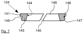
- the locking ring 4, 104 is formed by a disc 41, 141 and a subsequent paragraph 43, 143. It has an inner cone 44, 144. Externally, a groove 45, 145 is provided on the retaining ring 4, 104, which forms a stop surface 46, 146.
- the locking ring 4 is formed segmented, as this particular FIG. 6 can be seen.
- the retaining ring 4 is provided on the circumference of the disc 41 with cutouts 42.
- the paragraph 43 is provided with cutouts 48.
- the cutouts 42 and 48 are arranged on the retaining ring 4 in alternation.
- the in FIG. 7 Circlip 104 shown has a slot 140.
- the handle 5 is formed in a conventional manner. He has a paragraph 51 for receiving the valve stem 3.
- the heel 51 is surrounded by a lateral surface 53, whereby an annular receiving opening 52 for the housing 1 is formed between the shoulder 51 and the lateral surface 53.
- the handle 5 is locked to the spindle 3 by a circumferential and semi-annular in cross-section projection engages in the annular groove 38 of the spindle 3.
- the angle valve according to the invention allows a Ausdussch for a spindle made of plastic without affecting the function of the valve. Due to the correspondence of the inner cones 44, 144 of the locking ring 4, 104 with the cone 32 of the spindle 3, a solution is created which causes an additional clamping effect at increased pressure on the spindle during unscrewing or at elevated water pressures, so that the effect of the locking ring 4, 104 is additionally increased. Failure of the locking ring is thus avoided.
- an influence of the clamping effects can be caused.
- the locking ring 4, 104 made of plastic in combination with a spindle 3 from Plastic are the above effects of the locking ring improved because of the particularly suitable combination of materials.
Landscapes
- Engineering & Computer Science (AREA)
- General Engineering & Computer Science (AREA)
- Mechanical Engineering (AREA)
- Valve Housings (AREA)
- Mechanically-Actuated Valves (AREA)
- Lift Valve (AREA)
Description
- Die Erfindung betrifft ein Eckventil zum Anschluss sanitärer Armaturen mit einem Gehäuse, umfassend einen Eintrittsstutzen und einen Austrittsstutzen, zwischen denen ein Ventilsitz ausgebildet ist, der mit der Dichtfläche einer Ventilspindel korrespondiert, wobei die Ventilspindel aus Kunststoff hergestellt ist und ein Gewinde aufweist, das mit einem Gewinde im Gehäuse zusammenwirkt, sowie einem Sicherungsring zur Sicherung der Ventilspindel gegen Herausdrehen.
- Der Anschluss von Wasch- oder Spültischarmaturen erfolgt üblicherweise mit Hilfe von Eckventilen (vgl. bspw. Schell Eckregulierventil "Comfort" Bestell-Nr. 049160699). Die Eckventile weisen einen Eintrittsstutzen zum Anschluss an das Wandanschlussfitting der Sanitärinstallation des Gebäudes, einen Austrittsstutzen zum Anschluss der Auslaufarmatur und ein Absperrventil auf. Ein solches Eckventil ist bspw. aus der
DE 297 05 205 U1 bekannt. Die in den Eckventilen vorgesehene Ventilspindel zum Absperren bzw. Einstellen des Wasserzuflusses zu der angeschlossenen Armatur ist üblicherweise aus Messing hergestellt. Die Ventilspindeln sind mit Hilfe eines Griffs betätigbar. Zur Betätigung der Spindeln sind diese mit einem metrischen Feingewinde versehen, welches mit einem im Gehäuse des Eckventils vorgesehenen metallischen Gewinde korrespondiert. Die Ventilspindel ist gemäß DIN 3227 gegen Herausdrehen aus dem Gehäuse zu sichern. Dies erfolgt üblicherweise durch einen Runddrahtring aus Metall, der in einer Ringnut in dem Ventilgehäuse angeordnet ist. Bei vollständig geöffnetem Ventil wird das Gewinde der Ventilspindel gegen den Sicherungsring gepresst und die Spindel dadurch am Herausdrehen gehindert.
Neben den vorstehend beschriebenen Eckventilen aus Metall sind auch solche Eckventile bekannt, die unter anderem aus hygienischen Gründen vollständig oder teilweise aus Kunststoff hergestellt sind (vgl. bspw.AU 491 845 B2 - Hier will die Erfindung Abhilfe schaffen. Der Erfindung liegt die Aufgabe zu Grunde, ein Eckventil zu schaffen, bei dem eine Ausdrehsicherung für eine Kunststoffspindel geschaffen ist, die auch bei hohen Systemdrücken die Funktionssicherheit des Eckventils gewährleistet. Gemäß der Erfindung wird diese Aufgabe dadurch gelöst, dass der Sicherungsring einen Innenkonus aufweist, der mit einem Konus der Ventilspindel korrespondiert.
- Mit der Erfindung ist ein Eckventil geschaffen, bei dem eine zuverlässige Funktion auch bei hohem Systemdrücken innerhalb der Gebäudeinstallationsleitungen gewährleistet ist und gleichzeitig eine zuverlässige Sicherung gegen Ausdrehen der Spindel aus Kunststoff bereitstellt. Dies ist dadurch gewährleistet, dass aufgrund der korrespondierenden Konusse des Sicherungsrings einerseits und der Ventilspindel andererseits bei zunehmendem Druck auf die Spindel die Konusse miteinander verkeilen, wodurch eine zusätzliche Klemmkraft hervorgerufen ist. Somit ist bei Erhöhung des Drucks auf die Spindel auch eine Erhöhung der Klemmkraft gegen Herausdrehen hervorgerufen.
- Vorteilhaft liegt der Sicherungsring in einer Ringnut des Gehäuses ein und stützt sich mit einer Anschlagfläche gegen einen Absatz des Gehäuses ab. Durch diese Ausgestaltung ist gewährleistet, dass der Sicherungsring auch unter hohem Krafteinfluss der Spindel seine Position innerhalb des Eckventils beibehält und somit zuverlässig für die Sicherung der Spindel im Eckventil Sorge tragen kann.
- Bevorzugt ist der Sicherungsring aus Kunststoff. Die Herstellung des Sicherungsrings aus Kunststoff ist zum einen unter Kostengesichtspunkten attraktiv, zum anderen stellt sich hierdurch eine sehr gute Materialkombination zwischen der aus Kunststoff bestehenden Spindel und dem Sicherungsring ein.
- In Weiterbildung der Erfindung ist der Sicherungsring von einer Scheibe und einem Absatz gebildet. Hierbei handelt es sich um eine konstruktiv einfache Ausgestaltung, die einfach und damit preiswert herstellbar ist.
- In anderer Ausgestaltung der Erfindung weist der Sicherungsring Ausschnitte auf, die in der Scheibe ausgebildet sind, und Ausschnitte die in dem Absatz ausgebildet sind, wobei die Ausschnitte im Wechsel zueinander auf dem Sicherungsring angeordnet sind. Hierdurch ist die Montage des Sicherungsrings vereinfacht, da beim Zusammenbau des Eckventils in einfacher Weise ein Aufschieben des Sicherungsrings und damit ein Eintritt der Ausschnitte in die Ringnut des Gehäuses einfach möglich ist.
- In anderer Ausgestaltung der Erfindung weist der Sicherungsring einen Schlitz auf. Hierdurch ist der Sicherungsring geteilt, so dass auch hier die Möglichkeit besteht, in einfacher Weise den Sicherungsring im Eckventil zu montieren. Beim Aufschieben des Sicherungsrings in den Ventilstutzen drückt sich der Sicherungsring im Bereich des Spalts zusammen, so dass der Sicherungsring den Eintritt passieren kann und in die Ringnut eintreten kann, in der er sich dann wieder entspannt.
- Besonders bevorzugt ist das Gewinde der Ventilspindel ein Trapezgewinde. Die Ausbildung des Gewindes als Trapezgewinde hat sich bei der Verwendung von Ventilspindeln aus Kunststoff als besonders geeignet herausgestellt, weil das Trapezgewinde eine verhältnismäßig hohe Tragfähigkeit aufweist.
- Andere Weiterbildungen und Ausgestaltungen der Erfindung sind in den übrigen Unteransprüchen angegeben. Ausführungsbeispiele der Erfindung sind in den Zeichnungen dargestellt und werden nachfolgend im Einzelnen beschrieben. Es zeigen:
- Figur 1
- den Längsschnitt durch ein Eckventil, wobei in der unteren Hälfte der geschlossene, in der oberen Hälfte der offene Zustand dargestellt ist;
- Figur 2
- die Einzelheit "X" aus
Figur 1 in vergrößertem Maßstab; - Figur 3
- den Längsschnitt durch das Gehäuse eines Eckventils;
- Figur 4
- den Schnitt durch eine Ventilspindel;
- Figur 5
- den Schnitt entlang der Linie A-A in
Figur 6 - Figur 6
- die Ansicht eines Sicherungsrings und
- Figur 7
- den Schnitt durch einen Dichtungsring in anderer Ausbildung.
- Das als Ausführungsbeispiel gewählte Eckventil hat ein Gehäuse 1. Das Gehäuse 1 ist in der Regel aus Metall hergestellt. Es kann jedoch auch aus Kunststoff hergestellt sein. Es umfasst einen Eintrittsstutzen 11 sowie einen Austrittsstutzen 13 sowie einen Ventilstutzen 26, wobei Eintrittsstutzen 11 und Ventilstutzen 26 zueinander koaxial, der Austrittsstutzen 13 dazu rechtwinklig ausgerichtet sind. In dem Gehäuse 1 ist eine Ventilspindel 3 angeordnet, die mit einem Sicherungsring 4, 104 in dem Ventilstutzen 26 gesichert ist und mittels eines Griffs 5 betätigbar ist.
- Der Eintrittsstutzen 11 ist an seinem freien Ende außen mit einem Gewinde 12 versehen; innen ist eine Eintrittsbohrung 15 ausgebildet. Im Übergang zwischen dem Eintrittsstutzen 11 und dem Ventilstutzen 26 ist eine Ventilsitzbohrung 16 ausgebildet, die einen Ventilsitz 17 umfasst. An den Ventilsitz 17 schließt sich im Ventilstutzen 26 eine Spindelaufnahme 20 an. Von der Spindelaufnahme 20 geht eine Durchgangsbohrung 18 in Richtung des Austrittsstutzens 13 ab, der von einer Austrittsbohrung 19 durchsetzt ist. Außen ist der Austrittsstutzen 13 an seinem freien Ende mit einem Gewinde 14 versehen.
- In dem Ventilstutzen 26 schließt sich an die Spindelaufnahme 20 eine Freidrehung 21 an. Der Ventilstutzen 26 ist mit einem Innengewinde 22 für die Ventilspindel 3 versehen, das sich an die Freidrehung 21 anschließt. Das Innengewinde 22 endet in einer Ringnut 24, die am freien Ende des Ventilstutzens 26 einen nach innen gerichteten Absatz 23 ausbildet. Außen ist der Ventilstutzen 26 ebenfalls mit einem Absatz 25 versehen.
- Die Ventilspindel 3 ist rotationssymmetrisch aufgebaut. Sie ist aus Kunststoff hergestellt. Die Ventilspindel 3 weist in ihrem dem Eintrittsstutzen 11 abgewandten Bereich außen ein Gewinde 31 auf, das in montiertem Zustand mit dem Gewinde 22 des Gehäuses 1 korrespondiert. Benachbart zum Gewinde 31 ist an dem dem Eintrittsstutzen 11 abgewandten Ende ein Konus 32 ausgebildet. Innen ist in diesem Bereich der Ventilspindel 3 eine Griffaufnahme 37 vorgesehen, die abgesetzt ausgebildet ist und benachbart zu ihrem Boden eine Ringnut 38 aufweist.
- Die Ventilspindel 3 ist außen in ihrem mittleren Bereich mit einem Absatz 35 versehen, in den Ringnuten 36 eingebracht sind. In montiertem Zustand ist die Ventilspindel 3 durch in den Ringnuten 36 angeordnete Dichtungsringe 39 gegen die Spindelaufnahme 20 abgedichtet. An ihrem dem Eintrittsstutzen 11 zugewandten Ende ist eine Dichtfläche 34 ausgebildet, die in montiertem Zustand mit dem Ventilsitz 17 korrespondiert. Im Ausführungsbeispiel ist die Ventilspindel 3 mit einem Einsatz 33 versehen, der in eine ringförmige Ausnehmung eingesetzt ist. Der Einsatz 33 kann aus einem von der Ventilspindel 3 verschiedenen Material hergestellt sein. Der Einsatz 33 ist zur Verbesserung der fertigungstechnischen Bedingungen für die Herstellung der Ventilspindel 3 vorgesehen. Gleichzeitig lässt sich insbesondere durch Wahl eines stabilen Materials für den Einsatz 33 die Stabilität der Ventilspindel 3 insgesamt erhöhen. In Abwandlung des Ausführungsbeispiels besteht auch die Möglichkeit, auf die Ventilspindel 3 einen Stopfen aufzuspritzen.
- Am freien Ende des Ventilstutzens 26 ist der Sicherungsring 4, 104 für die Ventilspindel 3 angeordnet. Der Sicherungsring 4, 104 ist aus Kunststoff hergestellt und weist in seinem Zentrum eine Durchtrittsbohrung 49, 149 für die Ventilspindel 3 auf. Der Sicherungsring 4, 104 ist von einer Scheibe 41, 141 und einem sich daran anschließenden Absatz 43, 143 gebildet. Er weist einen Innenkonus 44, 144 auf. Außen ist an dem Sicherungsring 4, 104 eine Nut 45, 145 vorgesehen, die eine Anschlagfläche 46, 146 ausbildet. Auf der dem Eintrittsstutzen 11 in montiertem Zustand zugewandten Seite ist an dem Sicherungsring 4, 104 eine Phase 47, 147 vorgesehen.
- Im Ausführungsbeispiel nach den
Figuren 5 und 6 ist der Sicherungsring 4 segmentiert ausgebildet, wie dies insbesondereFigur 6 zu entnehmen ist. Hierzu ist der Sicherungsring 4 auf dem Umfang der Scheibe 41 mit Ausschnitten 42 versehen. Gleichzeitig ist der Absatz 43 mit Ausschnitten 48 versehen. Die Ausschnitte 42 und 48 sind an den Sicherungsring 4 im Wechsel zueinander angeordnet. Der inFigur 7 dargestellte Sicherungsring 104 weist einen Schlitz 140 auf. - Der Griff 5 ist in an sich bekannter Weise ausgebildet. Er weist einen Absatz 51 zur Aufnahme der Ventilspindel 3 auf. Der Absatz 51 ist umgeben von einer Mantelfläche 53, wodurch zwischen Absatz 51 und Mantelfläche 53 eine ringförmige Aufnahmeöffnung 52 für das Gehäuse 1 ausgebildet ist. Der Griff 5 ist mit der Spindel 3 verrastet, indem ein umlaufender und im Querschnitt halbringförmiger Vorsprung in die Ringnut 38 der Spindel 3 eingreift.
- Das erfindungsgemäße Eckventil ermöglicht eine Ausdrehsicherung für eine Spindel aus Kunststoff ohne Beeinträchtigung der Funktion des Ventils. Aufgrund der Korrespondenz der Innenkonusse 44, 144 des Sicherungsrings 4, 104 mit dem Konus 32 der Spindel 3 ist eine Lösung geschaffen, die bei erhöhtem Druck auf die Spindel beim Ausdrehen bzw. bei erhöhten Wasserdrücken eine zusätzliche Klemmwirkung hervorruft, so dass die Wirkung des Sicherungsrings 4, 104 zusätzlich erhöht wird. Ein Versagen des Sicherungsrings ist somit vermieden. Durch die Variierung der Winkel des Innenkonus 44, 144 einerseits und des Konus 32 andererseits kann eine Beeinflussung der Klemmwirkungen hervorgerufen werden. Insbesondere bei der Verwendung des Sicherungsrings 4, 104 aus Kunststoff in Kombination mit einer Spindel 3 aus Kunststoff sind die vorbeschriebenen Wirkungen des Sicherungsrings wegen der besonders geeigneten Materialkombination verbessert.
Claims (10)
- Eckventil zum Anschluss sanitärer Armaturen mit einem Gehäuse (1), umfassend einen Eintrittsstutzen (11) und einen Austrittsstutzen (13), zwischen denen ein Ventilsitz (17) ausgebildet ist, der mit der Dichtfläche (34) einer Ventilspindel (3) des Eckventils korrespondiert, wobei die Ventilspindel (3) aus Kunststoff hergestellt ist und ein Gewinde (31) aufweist, das mit einem Gewinde (22) im Gehäuse (1) zusammenwirkt, sowie einem Sicherungsring (4) zur Sicherung der Ventilspindel (3) gegen Herausdrehen, dadurch gekennzeichnet, dass der Sicherungsring (4, 104) einen Innenkonus (44, 144) aufweist, der mit einem Konus (32) der Ventilspindel (3) korrespondiert.
- Eckventil nach Anspruch 1, dadurch gekennzeichnet, dass der Sicherungsring (4, 104) in einer Ringnut (24) des Gehäuses (1) einliegt und sich mit einer Anschlagfläche (46, 146) gegen einen Absatz (23) des Gehäuses (1) abstützt.
- Eckventil nach Anspruch 1 oder 2, dadurch gekennzeichnet, dass der Winkel des Innenkonus (44, 144) des Sicherungsrings (4, 104) gleich dem Winkel des Konus (32) der Ventilspindel (3) ist.
- Eckventil nach Anspruch 1 oder 2, dadurch gekennzeichnet, dass der Winkel des Innenkonus (44, 144) des Sicherungsrings (4, 104) ungleich dem Winkel des Konus (32) der Ventilspindel (3) ist.
- Eckventil nach einem der vorgenannten Ansprüche, dadurch gekennzeichnet, dass der Sicherungsring (4, 104) aus Kunststoff ist.
- Eckventil nach einem der vorgenannten Ansprüche, dadurch gekennzeichnet, dass der Sicherungsring (4, 104) von einer Scheibe (41, 141) und einem Absatz (43, 143) gebildet ist.
- Eckventil nach Anspruch 6, dadurch gekennzeichnet, dass der Sicherungsring (4) Ausschnitte (42) aufweist, die in der Scheibe (41) ausgebildet sind, und Ausschnitte (48) aufweist, die in dem Absatz (43) ausgebildet sind, wobei die Ausschnitte (42, 48) im Wechsel zueinander auf dem Sicherungsring (4) angeordnet sind.
- Eckventil nach einem der vorgenannten Ansprüche, dadurch gekennzeichnet, dass der Sicherungsring (104) einen Schlitz (14) aufweist.
- Eckventil nach einem der vorgenannten Ansprüche, dadurch gekennzeichnet, dass das Gewinde (31) der Ventilspindel (3) ein Trapezgewinde ist.
- Eckventil nach einem der vorgenannten Ansprüche, dadurch gekennzeichnet, dass das Gehäuse (1) aus Kunststoff ist.
Priority Applications (1)
| Application Number | Priority Date | Filing Date | Title |
|---|---|---|---|
| PL16805341T PL3240965T3 (pl) | 2015-11-26 | 2016-11-24 | Zawór kątowy |
Applications Claiming Priority (2)
| Application Number | Priority Date | Filing Date | Title |
|---|---|---|---|
| DE102015120552 | 2015-11-26 | ||
| PCT/EP2016/078615 WO2017089434A1 (de) | 2015-11-26 | 2016-11-24 | Eckventil |
Publications (2)
| Publication Number | Publication Date |
|---|---|
| EP3240965A1 EP3240965A1 (de) | 2017-11-08 |
| EP3240965B1 true EP3240965B1 (de) | 2018-09-26 |
Family
ID=57471819
Family Applications (1)
| Application Number | Title | Priority Date | Filing Date |
|---|---|---|---|
| EP16805341.1A Not-in-force EP3240965B1 (de) | 2015-11-26 | 2016-11-24 | Eckventil |
Country Status (5)
| Country | Link |
|---|---|
| EP (1) | EP3240965B1 (de) |
| CN (1) | CN108496032A (de) |
| ES (1) | ES2699708T3 (de) |
| PL (1) | PL3240965T3 (de) |
| WO (1) | WO2017089434A1 (de) |
Family Cites Families (4)
| Publication number | Priority date | Publication date | Assignee | Title |
|---|---|---|---|---|
| AU491845B2 (en) * | 1973-09-03 | 1978-03-28 | Upl Group Ltd. | Tap |
| DE29705205U1 (de) * | 1997-03-14 | 1997-06-05 | Schell GmbH & Co. KG, 57462 Olpe | Eckventil |
| BRPI1000397B1 (pt) * | 2010-05-10 | 2020-06-16 | Yukio Oizumi | Registro com válvula bidirecional de fluxo de água, com instalação em hidrômetro para sistema de aferição de consumo |
| CN203146832U (zh) * | 2013-02-06 | 2013-08-21 | 岑利泽 | 角阀 |
-
2016
- 2016-11-24 CN CN201680068991.4A patent/CN108496032A/zh active Pending
- 2016-11-24 PL PL16805341T patent/PL3240965T3/pl unknown
- 2016-11-24 EP EP16805341.1A patent/EP3240965B1/de not_active Not-in-force
- 2016-11-24 ES ES16805341T patent/ES2699708T3/es active Active
- 2016-11-24 WO PCT/EP2016/078615 patent/WO2017089434A1/de not_active Ceased
Non-Patent Citations (1)
| Title |
|---|
| None * |
Also Published As
| Publication number | Publication date |
|---|---|
| EP3240965A1 (de) | 2017-11-08 |
| CN108496032A (zh) | 2018-09-04 |
| PL3240965T3 (pl) | 2019-02-28 |
| ES2699708T3 (es) | 2019-02-12 |
| WO2017089434A1 (de) | 2017-06-01 |
Similar Documents
| Publication | Publication Date | Title |
|---|---|---|
| DE8429086U1 (de) | Kugelventil mit einem verschlussring | |
| EP1696158A1 (de) | Ventiloberteil | |
| DE102007059315A1 (de) | Druckminderer | |
| EP4060210B1 (de) | Rückflussverhindererventil | |
| DE3827469A1 (de) | Dichtungsring fuer haehne | |
| EP2292852B1 (de) | Sanitärarmatur und Dichtring für eine Sanitärarmatur | |
| EP2206939B1 (de) | Armatur | |
| EP3240965A1 (de) | Eckventil | |
| DE202013006947U1 (de) | Mutter mit integrierter Sicherung | |
| EP3001081B1 (de) | Eckventil mit Handrad | |
| DE3128133C2 (de) | Verschlußklappe für Luftleitungen | |
| EP2313661B1 (de) | Konteranordnung | |
| DE3834997C2 (de) | ||
| DE10202560A1 (de) | Thermostat-Mischventil | |
| DE4405913C2 (de) | Sicherheitsventil | |
| DE29705205U1 (de) | Eckventil | |
| DE20008679U1 (de) | Ventiloberteil für Armaturen | |
| DE20116280U1 (de) | Ventiloberteil für Armaturen | |
| DE60203727T2 (de) | Vorrichtung zur befestigung eines gerätes zur brechung der akustischen impedanz eines stiftes | |
| DE29905140U1 (de) | Eckventil | |
| DE102005012705B4 (de) | Lösbare druckdichte Fluid-Verbindung | |
| DE681191C (de) | Rohrkupplung, insbesondere fuer Kaeltemittelleitungen | |
| DE4128007C2 (de) | Sicherheitsventil | |
| EP2461076B1 (de) | Seitenventil | |
| EP3062003B1 (de) | Einhandhebelkartusche |
Legal Events
| Date | Code | Title | Description |
|---|---|---|---|
| PUAI | Public reference made under article 153(3) epc to a published international application that has entered the european phase |
Free format text: ORIGINAL CODE: 0009012 |
|
| 17P | Request for examination filed |
Effective date: 20170612 |
|
| AK | Designated contracting states |
Kind code of ref document: A1 Designated state(s): AL AT BE BG CH CY CZ DE DK EE ES FI FR GB GR HR HU IE IS IT LI LT LU LV MC MK MT NL NO PL PT RO RS SE SI SK SM TR |
|
| AX | Request for extension of the european patent |
Extension state: BA ME |
|
| GRAP | Despatch of communication of intention to grant a patent |
Free format text: ORIGINAL CODE: EPIDOSNIGR1 |
|
| DAV | Request for validation of the european patent (deleted) | ||
| DAX | Request for extension of the european patent (deleted) | ||
| INTG | Intention to grant announced |
Effective date: 20180607 |
|
| GRAS | Grant fee paid |
Free format text: ORIGINAL CODE: EPIDOSNIGR3 |
|
| GRAA | (expected) grant |
Free format text: ORIGINAL CODE: 0009210 |
|
| AK | Designated contracting states |
Kind code of ref document: B1 Designated state(s): AL AT BE BG CH CY CZ DE DK EE ES FI FR GB GR HR HU IE IS IT LI LT LU LV MC MK MT NL NO PL PT RO RS SE SI SK SM TR |
|
| REG | Reference to a national code |
Ref country code: GB Ref legal event code: FG4D Free format text: NOT ENGLISH |
|
| REG | Reference to a national code |
Ref country code: CH Ref legal event code: EP |
|
| REG | Reference to a national code |
Ref country code: AT Ref legal event code: REF Ref document number: 1046406 Country of ref document: AT Kind code of ref document: T Effective date: 20181015 |
|
| REG | Reference to a national code |
Ref country code: IE Ref legal event code: FG4D Free format text: LANGUAGE OF EP DOCUMENT: GERMAN |
|
| REG | Reference to a national code |
Ref country code: DE Ref legal event code: R096 Ref document number: 502016002114 Country of ref document: DE |
|
| REG | Reference to a national code |
Ref country code: NL Ref legal event code: MP Effective date: 20180926 |
|
| PG25 | Lapsed in a contracting state [announced via postgrant information from national office to epo] |
Ref country code: GR Free format text: LAPSE BECAUSE OF FAILURE TO SUBMIT A TRANSLATION OF THE DESCRIPTION OR TO PAY THE FEE WITHIN THE PRESCRIBED TIME-LIMIT Effective date: 20181227 Ref country code: NO Free format text: LAPSE BECAUSE OF FAILURE TO SUBMIT A TRANSLATION OF THE DESCRIPTION OR TO PAY THE FEE WITHIN THE PRESCRIBED TIME-LIMIT Effective date: 20181226 Ref country code: LT Free format text: LAPSE BECAUSE OF FAILURE TO SUBMIT A TRANSLATION OF THE DESCRIPTION OR TO PAY THE FEE WITHIN THE PRESCRIBED TIME-LIMIT Effective date: 20180926 Ref country code: BG Free format text: LAPSE BECAUSE OF FAILURE TO SUBMIT A TRANSLATION OF THE DESCRIPTION OR TO PAY THE FEE WITHIN THE PRESCRIBED TIME-LIMIT Effective date: 20181226 Ref country code: RS Free format text: LAPSE BECAUSE OF FAILURE TO SUBMIT A TRANSLATION OF THE DESCRIPTION OR TO PAY THE FEE WITHIN THE PRESCRIBED TIME-LIMIT Effective date: 20180926 Ref country code: FI Free format text: LAPSE BECAUSE OF FAILURE TO SUBMIT A TRANSLATION OF THE DESCRIPTION OR TO PAY THE FEE WITHIN THE PRESCRIBED TIME-LIMIT Effective date: 20180926 |
|
| REG | Reference to a national code |
Ref country code: LT Ref legal event code: MG4D |
|
| REG | Reference to a national code |
Ref country code: ES Ref legal event code: FG2A Ref document number: 2699708 Country of ref document: ES Kind code of ref document: T3 Effective date: 20190212 |
|
| PG25 | Lapsed in a contracting state [announced via postgrant information from national office to epo] |
Ref country code: AL Free format text: LAPSE BECAUSE OF FAILURE TO SUBMIT A TRANSLATION OF THE DESCRIPTION OR TO PAY THE FEE WITHIN THE PRESCRIBED TIME-LIMIT Effective date: 20180926 Ref country code: LV Free format text: LAPSE BECAUSE OF FAILURE TO SUBMIT A TRANSLATION OF THE DESCRIPTION OR TO PAY THE FEE WITHIN THE PRESCRIBED TIME-LIMIT Effective date: 20180926 Ref country code: HR Free format text: LAPSE BECAUSE OF FAILURE TO SUBMIT A TRANSLATION OF THE DESCRIPTION OR TO PAY THE FEE WITHIN THE PRESCRIBED TIME-LIMIT Effective date: 20180926 |
|
| PG25 | Lapsed in a contracting state [announced via postgrant information from national office to epo] |
Ref country code: IS Free format text: LAPSE BECAUSE OF FAILURE TO SUBMIT A TRANSLATION OF THE DESCRIPTION OR TO PAY THE FEE WITHIN THE PRESCRIBED TIME-LIMIT Effective date: 20190126 Ref country code: EE Free format text: LAPSE BECAUSE OF FAILURE TO SUBMIT A TRANSLATION OF THE DESCRIPTION OR TO PAY THE FEE WITHIN THE PRESCRIBED TIME-LIMIT Effective date: 20180926 Ref country code: RO Free format text: LAPSE BECAUSE OF FAILURE TO SUBMIT A TRANSLATION OF THE DESCRIPTION OR TO PAY THE FEE WITHIN THE PRESCRIBED TIME-LIMIT Effective date: 20180926 Ref country code: NL Free format text: LAPSE BECAUSE OF FAILURE TO SUBMIT A TRANSLATION OF THE DESCRIPTION OR TO PAY THE FEE WITHIN THE PRESCRIBED TIME-LIMIT Effective date: 20180926 Ref country code: CZ Free format text: LAPSE BECAUSE OF FAILURE TO SUBMIT A TRANSLATION OF THE DESCRIPTION OR TO PAY THE FEE WITHIN THE PRESCRIBED TIME-LIMIT Effective date: 20180926 |
|
| PG25 | Lapsed in a contracting state [announced via postgrant information from national office to epo] |
Ref country code: SK Free format text: LAPSE BECAUSE OF FAILURE TO SUBMIT A TRANSLATION OF THE DESCRIPTION OR TO PAY THE FEE WITHIN THE PRESCRIBED TIME-LIMIT Effective date: 20180926 Ref country code: PT Free format text: LAPSE BECAUSE OF FAILURE TO SUBMIT A TRANSLATION OF THE DESCRIPTION OR TO PAY THE FEE WITHIN THE PRESCRIBED TIME-LIMIT Effective date: 20190126 Ref country code: SM Free format text: LAPSE BECAUSE OF FAILURE TO SUBMIT A TRANSLATION OF THE DESCRIPTION OR TO PAY THE FEE WITHIN THE PRESCRIBED TIME-LIMIT Effective date: 20180926 |
|
| REG | Reference to a national code |
Ref country code: DE Ref legal event code: R097 Ref document number: 502016002114 Country of ref document: DE |
|
| PG25 | Lapsed in a contracting state [announced via postgrant information from national office to epo] |
Ref country code: MC Free format text: LAPSE BECAUSE OF FAILURE TO SUBMIT A TRANSLATION OF THE DESCRIPTION OR TO PAY THE FEE WITHIN THE PRESCRIBED TIME-LIMIT Effective date: 20180926 Ref country code: LU Free format text: LAPSE BECAUSE OF NON-PAYMENT OF DUE FEES Effective date: 20181124 Ref country code: DK Free format text: LAPSE BECAUSE OF FAILURE TO SUBMIT A TRANSLATION OF THE DESCRIPTION OR TO PAY THE FEE WITHIN THE PRESCRIBED TIME-LIMIT Effective date: 20180926 |
|
| PLBE | No opposition filed within time limit |
Free format text: ORIGINAL CODE: 0009261 |
|
| STAA | Information on the status of an ep patent application or granted ep patent |
Free format text: STATUS: NO OPPOSITION FILED WITHIN TIME LIMIT |
|
| REG | Reference to a national code |
Ref country code: BE Ref legal event code: MM Effective date: 20181130 |
|
| REG | Reference to a national code |
Ref country code: IE Ref legal event code: MM4A |
|
| 26N | No opposition filed |
Effective date: 20190627 |
|
| PG25 | Lapsed in a contracting state [announced via postgrant information from national office to epo] |
Ref country code: FR Free format text: LAPSE BECAUSE OF NON-PAYMENT OF DUE FEES Effective date: 20181126 Ref country code: SI Free format text: LAPSE BECAUSE OF FAILURE TO SUBMIT A TRANSLATION OF THE DESCRIPTION OR TO PAY THE FEE WITHIN THE PRESCRIBED TIME-LIMIT Effective date: 20180926 Ref country code: IE Free format text: LAPSE BECAUSE OF NON-PAYMENT OF DUE FEES Effective date: 20181124 |
|
| PG25 | Lapsed in a contracting state [announced via postgrant information from national office to epo] |
Ref country code: BE Free format text: LAPSE BECAUSE OF NON-PAYMENT OF DUE FEES Effective date: 20181130 |
|
| PG25 | Lapsed in a contracting state [announced via postgrant information from national office to epo] |
Ref country code: MT Free format text: LAPSE BECAUSE OF FAILURE TO SUBMIT A TRANSLATION OF THE DESCRIPTION OR TO PAY THE FEE WITHIN THE PRESCRIBED TIME-LIMIT Effective date: 20180926 |
|
| PGFP | Annual fee paid to national office [announced via postgrant information from national office to epo] |
Ref country code: DE Payment date: 20191205 Year of fee payment: 4 |
|
| PGFP | Annual fee paid to national office [announced via postgrant information from national office to epo] |
Ref country code: ES Payment date: 20191216 Year of fee payment: 4 Ref country code: PL Payment date: 20191112 Year of fee payment: 4 Ref country code: IT Payment date: 20191130 Year of fee payment: 4 |
|
| PG25 | Lapsed in a contracting state [announced via postgrant information from national office to epo] |
Ref country code: TR Free format text: LAPSE BECAUSE OF FAILURE TO SUBMIT A TRANSLATION OF THE DESCRIPTION OR TO PAY THE FEE WITHIN THE PRESCRIBED TIME-LIMIT Effective date: 20180926 |
|
| PG25 | Lapsed in a contracting state [announced via postgrant information from national office to epo] |
Ref country code: MK Free format text: LAPSE BECAUSE OF NON-PAYMENT OF DUE FEES Effective date: 20180926 Ref country code: SE Free format text: LAPSE BECAUSE OF FAILURE TO SUBMIT A TRANSLATION OF THE DESCRIPTION OR TO PAY THE FEE WITHIN THE PRESCRIBED TIME-LIMIT Effective date: 20180926 Ref country code: CY Free format text: LAPSE BECAUSE OF FAILURE TO SUBMIT A TRANSLATION OF THE DESCRIPTION OR TO PAY THE FEE WITHIN THE PRESCRIBED TIME-LIMIT Effective date: 20180926 Ref country code: HU Free format text: LAPSE BECAUSE OF FAILURE TO SUBMIT A TRANSLATION OF THE DESCRIPTION OR TO PAY THE FEE WITHIN THE PRESCRIBED TIME-LIMIT; INVALID AB INITIO Effective date: 20161124 |
|
| REG | Reference to a national code |
Ref country code: CH Ref legal event code: PL |
|
| PG25 | Lapsed in a contracting state [announced via postgrant information from national office to epo] |
Ref country code: CH Free format text: LAPSE BECAUSE OF NON-PAYMENT OF DUE FEES Effective date: 20191130 Ref country code: LI Free format text: LAPSE BECAUSE OF NON-PAYMENT OF DUE FEES Effective date: 20191130 |
|
| REG | Reference to a national code |
Ref country code: DE Ref legal event code: R119 Ref document number: 502016002114 Country of ref document: DE |
|
| GBPC | Gb: european patent ceased through non-payment of renewal fee |
Effective date: 20201124 |
|
| PG25 | Lapsed in a contracting state [announced via postgrant information from national office to epo] |
Ref country code: IT Free format text: LAPSE BECAUSE OF NON-PAYMENT OF DUE FEES Effective date: 20201124 |
|
| PG25 | Lapsed in a contracting state [announced via postgrant information from national office to epo] |
Ref country code: GB Free format text: LAPSE BECAUSE OF NON-PAYMENT OF DUE FEES Effective date: 20201124 Ref country code: DE Free format text: LAPSE BECAUSE OF NON-PAYMENT OF DUE FEES Effective date: 20210601 |
|
| REG | Reference to a national code |
Ref country code: ES Ref legal event code: FD2A Effective date: 20220201 |
|
| PG25 | Lapsed in a contracting state [announced via postgrant information from national office to epo] |
Ref country code: ES Free format text: LAPSE BECAUSE OF NON-PAYMENT OF DUE FEES Effective date: 20201125 |
|
| PG25 | Lapsed in a contracting state [announced via postgrant information from national office to epo] |
Ref country code: PL Free format text: LAPSE BECAUSE OF NON-PAYMENT OF DUE FEES Effective date: 20201124 |
|
| REG | Reference to a national code |
Ref country code: AT Ref legal event code: MM01 Ref document number: 1046406 Country of ref document: AT Kind code of ref document: T Effective date: 20211124 |
|
| PG25 | Lapsed in a contracting state [announced via postgrant information from national office to epo] |
Ref country code: AT Free format text: LAPSE BECAUSE OF NON-PAYMENT OF DUE FEES Effective date: 20211124 |