EP3241463B1 - Nabenkonstruktion für einen drehbaren stuhl - Google Patents
Nabenkonstruktion für einen drehbaren stuhl Download PDFInfo
- Publication number
- EP3241463B1 EP3241463B1 EP17397511.1A EP17397511A EP3241463B1 EP 3241463 B1 EP3241463 B1 EP 3241463B1 EP 17397511 A EP17397511 A EP 17397511A EP 3241463 B1 EP3241463 B1 EP 3241463B1
- Authority
- EP
- European Patent Office
- Prior art keywords
- hub
- shaft
- chair
- axial direction
- brake disc
- Prior art date
- Legal status (The legal status is an assumption and is not a legal conclusion. Google has not performed a legal analysis and makes no representation as to the accuracy of the status listed.)
- Active
Links
Images


Classifications
-
- A—HUMAN NECESSITIES
- A47—FURNITURE; DOMESTIC ARTICLES OR APPLIANCES; COFFEE MILLS; SPICE MILLS; SUCTION CLEANERS IN GENERAL
- A47C—CHAIRS; SOFAS; BEDS
- A47C3/00—Chairs characterised by structural features; Chairs or stools with rotatable or vertically-adjustable seats
- A47C3/18—Chairs or stools with rotatable seat
- A47C3/185—Chairs or stools with rotatable seat self-returning to the original position
-
- A—HUMAN NECESSITIES
- A47—FURNITURE; DOMESTIC ARTICLES OR APPLIANCES; COFFEE MILLS; SPICE MILLS; SUCTION CLEANERS IN GENERAL
- A47C—CHAIRS; SOFAS; BEDS
- A47C7/00—Parts, details, or accessories of chairs or stools
- A47C7/002—Chair or stool bases
- A47C7/006—Chair or stool bases with castors
Definitions
- the present invention relates to a hub construction for a rotatable chair, which automatically returns to its initial position when the chair is relieved, comprising a vertical shaft fastenable to a lower side of a seat of the chair and a hub fastenable on a leg portion of the chair, to which hub a lower portion of the shaft is rotatably fastened, whereby return movement is achieved by means of a cam surface acting in an axial direction on an end of a spring loaded sleeve enclosing the shaft, which cam surface is arranged to cooperate with a radially directed guide pin.
- a brake For obtaining higher friction when the hub is loaded, it has been provided with a brake.
- patent JP H07222637 A there is disclosed a hub construction for a rotatable chair, which automatically returns to the initial position, when the chair is relieved.
- patent KR 20100106833 A there is disclosed a rotatable chair.
- the hub construction comprises a spring device, which is compressed when the hub is axially loaded, i.e.vertically, whereby a brake disc causes higher friction.
- the spring device is preferably a disc spring, in particular a pair of disc springs.
- FIG. 1 shows an embodiment of a hub construction according to FI 83590 seen in a side view
- Fig. 2 shows an example of a hub construction according to the invention
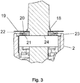
- Fig. 3 shows a detail of the construction according to the invention as indicated by B in Fig. 2 .
- a prior art hub construction according to Fig. 1 comprises a vertical shaft 1, which is stationary fastened to the underside of a seat of a rotatable chair, and a hub 2 on the leg portion of the chair, to which hub 2 the lower portion of the shaft 1 is rotatably fastened.
- the hub 2 has externally the form of a truncated pyramid, whereby each side 2a is provided with threaded fastening holes 3 for the legs of the chair.
- the vertical shaft 1 has in its lower portion a radially projecting guide pin 4, which is arranged to act against a cam surface 5 acting in the axial direction and located on the end of an axially movable sleeve 6 spring-loaded in the direction against the cam surface 5, which sleeve encloses the shaft 1.
- the sleeve 6 is pushed by the spring force against the guide pin 4 on the axially stationary shaft 1, whereby the cam surface 5 via the guide pin 4 forces the shaft 1 to turn until the guide pin 4 sets against the stable rest point of the cam surface 5, at which rest point the height of the sleeve 6 is at its lowest.
- the seat of the chair and thereby the shaft 1 can be turned without limitation by an arbitrary number of revolutions in either direction, after which it can return, when relieved, to its initial position by the shortest route, which results in a return movement of maximum 180°.
- a roller 7 is preferably mounted around the guide pin 4 for ensuring that the friction between the cam surface 5 and the guide pin 4 is as low as possible.
- a displacement of the shaft 1 axially in the hub 2 is prevented by means of an upper 8 and a lower 9 locking washer.
- the shaft is mounted in the hub by means of a plain bearing 11 in the lower portion and a ball bearing 12 in the upper portion.
- the spring-loaded sleeve 6 has a constant inner diameter mainly corresponding to the diameter of the shaft 1 along its whole length and an outer diameter, which nearest to the cam surface 5 mainly corresponds to the inner diameter of the hub 2 and via a radial extension 14 decreases to a smaller diameter mainly corresponding to the inner diameter of the pressure spring 10, whereby the pressure spring is arranged to enclose the narrower portion of the sleeve 6, the radial extension 14 serving as a contact surface.
- the shaft 1 primarily serves as a guide for the sleeve 6, and a robust construction is achieved.
- the sleeve 6 is preferably provided with at least a radially projecting key 15, which is arranged to be seated in an axial groove 16 on the inner peripheral surface of the hub 2.
- the cam surface 5 is preferably formed as a radially directed end surface continually ascending along two curves of 180° in opposite directions from the lowest initial point.
- Fig. 2 shows a hub construction according to the invention. Contrary to the hub in Fig. 1 , this construction is intended for being fitted into a separate chair base and does thus not have the form nor the fastening holes as the construction in Fig. 1 , but has straight sides. However, this is of no significance in regard to the features characteristic for the invention.
- the numbered components in Fig. 2 correspond, where applicable, to the ones shown in Fig. 1 .
- Fig. 3 shows the upper part of the hub construction in Fig. 2 , as indicated by B, in greater detail.
- the shaft 1 is arranged in the hub 2 via the ball bearing 12 in such a way that the shaft is axially movable in the inner ring of the bearing. At the lower end of the shaft there is thus space for an axial movement.
- the lower end of the shaft can have a central guide pin 17.
- a collar 18 In the upper part of the shaft there is a collar 18, under which a brake disc 19 is arranged. Under the brake disc 19, there are two opposite disc spring washers 20, 21 mounted around the shaft 1 in such a way that the inner periphery of the lower washer lies against a supporting plane 24, which here consists of the inner ring of the bearing 12.
- a supporting plane 24 which here consists of the inner ring of the bearing 12.
- the surface of the brake disc 19 can be treated in order to provide higher or lower friction against the hub.
- the brake disc can, for example, be lightly blasted.
- the brake disc 19 can be manufactured of same spring steel as the disc spring plates 20, 21.
- the distance between the brake disc 19 and the brake surface 22 on the hub can be less than 2 mm when the hub is unloaded.
Landscapes
- Braking Arrangements (AREA)
Claims (3)
- Nabenkonstruktion für einen drehbaren Stuhl, welche automatisch in ihre ursprüngliche Position zurückkehrt, wenn der Stuhl entlastet ist, eine vertikale Welle (1), die an einer Unterseite einer Sitzfläche des Stuhls befestigbar ist, und eine Nabe (2) umfassend, welche an einem Beinabschnitt des Stuhls befestigbar ist, an dessen Nabe (2) ein unterer Abschnitt der Welle (1) drehbar befestigt ist, wobei die Rückkehrbewegung anhand einer Nockenoberfläche (5) erreicht wird, die in eine axiale Richtung an einem Ende einer federbelasteten Hülse (6) wirkt, welche die Welle (1) einschließt, wobei die Nockenoberfläche (5) angeordnet ist, um mit einem radial gerichteten Führungsstift (4), welcher an dem unteren Abschnitt der Welle (1) befestigt ist, zusammenzuwirken, und die federbelastete Hülse (6) drehstarr an der Nabe (2) befestigt ist, dadurch gekennzeichnet, dass die Welle (1) in die axiale Richtung beweglich in ihren Lagern (11, 12) in der Nabe angeordnet ist; die Welle (1) mit einem Kragen (18) in ihrem oberen Teil bereitgestellt ist; und eine Federvorrichtung (20, 21), die sich zwischen dem Kragen (18) und einer Stützebene (24) befindet und eine Bremsscheibe (19) derart in der Nabe (2) angeordnet sind, dass wenn die Welle (1) vertikal belastet ist, die Welle (1) in die axiale Richtung verschoben wird und die Federvorrichtung (20, 21) zusammengedrückt wird, sodass die Bremsscheibe (19) mit einer Oberfläche (22) auf der Nabe (2) in Kontakt kommt.
- Nabenkonstruktion nach Anspruch 1, dadurch gekennzeichnet, dass die Bremsscheibe (19) gestrahlt ist, um eine stärkere Reibung zu erhalten.
- Nabenkonstruktion nach Anspruch 1 oder 2, dadurch gekennzeichnet, dass die Beweglichkeit der Welle (1) in die axiale Richtung höchstens 2 mm beträgt.
Priority Applications (1)
| Application Number | Priority Date | Filing Date | Title |
|---|---|---|---|
| PL17397511T PL3241463T3 (pl) | 2016-05-04 | 2017-04-26 | Konstrukcja piasty dla krzesła obrotowego |
Applications Claiming Priority (1)
| Application Number | Priority Date | Filing Date | Title |
|---|---|---|---|
| FI20165386A FI126841B (sv) | 2016-05-04 | 2016-05-04 | Navkonstruktion för en roterbar stol |
Publications (2)
| Publication Number | Publication Date |
|---|---|
| EP3241463A1 EP3241463A1 (de) | 2017-11-08 |
| EP3241463B1 true EP3241463B1 (de) | 2019-01-23 |
Family
ID=58699077
Family Applications (1)
| Application Number | Title | Priority Date | Filing Date |
|---|---|---|---|
| EP17397511.1A Active EP3241463B1 (de) | 2016-05-04 | 2017-04-26 | Nabenkonstruktion für einen drehbaren stuhl |
Country Status (6)
| Country | Link |
|---|---|
| US (1) | US10080439B2 (de) |
| EP (1) | EP3241463B1 (de) |
| CN (1) | CN107343718B (de) |
| DK (1) | DK3241463T3 (de) |
| FI (1) | FI126841B (de) |
| PL (1) | PL3241463T3 (de) |
Families Citing this family (2)
| Publication number | Priority date | Publication date | Assignee | Title |
|---|---|---|---|---|
| TWI669086B (zh) * | 2017-05-26 | 2019-08-21 | 倪培堯 | 可復位氣壓棒模組 |
| EP4674316A1 (de) | 2024-07-04 | 2026-01-07 | AF Solutions Ab Oy | Nabe für einen drehbaren stuhl |
Family Cites Families (14)
| Publication number | Priority date | Publication date | Assignee | Title |
|---|---|---|---|---|
| US1532354A (en) * | 1923-11-09 | 1925-04-07 | Joseph S Walton | Revolving stool |
| US2755842A (en) * | 1951-12-08 | 1956-07-24 | Peter G Caramelli | Center-controlled movable seat construction |
| US3223376A (en) * | 1963-11-18 | 1965-12-14 | Stewart Warner Corp | Self-returning chair control |
| US3837611A (en) * | 1973-10-01 | 1974-09-24 | Keystone Consolidated Ind Inc | Swivel construction for a chair |
| FI83590C (sv) | 1989-05-10 | 1991-08-12 | F Ma Mekrapid | Navkonstruktion för en roterbar stol |
| US5342012A (en) * | 1992-01-28 | 1994-08-30 | Ryu Chang Keun | Height adjusting mechanism for swivel chair |
| JPH07222637A (ja) | 1994-02-12 | 1995-08-22 | Sasazu Susumu | 椅子の方向復元装置 |
| DE9416289U1 (de) * | 1994-10-12 | 1994-12-01 | SIFA Sitzfabrik GmbH, 92237 Sulzbach-Rosenberg | Rückstellung für Drehstühle |
| CN201079167Y (zh) * | 2007-04-29 | 2008-07-02 | 郭瑞媚 | 一种改进的转椅 |
| CN201223158Y (zh) * | 2008-05-01 | 2009-04-22 | 东莞市美缇皮具有限公司 | 主动式动力座椅装置 |
| KR20100106833A (ko) | 2009-03-24 | 2010-10-04 | 박종화 | 안전의자 |
| IT1398798B1 (it) * | 2010-03-17 | 2013-03-18 | Stylgame S R L | Dispositivo di movimentazione per un elemento di arredamento |
| JP2015028360A (ja) * | 2013-07-30 | 2015-02-12 | 日立オートモティブシステムズ株式会社 | 支持装置及び回動位置復帰装置 |
| CN203493160U (zh) * | 2013-10-12 | 2014-03-26 | 青岛三弘精密器械有限公司 | 一种自动回旋回位座椅弹簧气压棒 |
-
2016
- 2016-05-04 FI FI20165386A patent/FI126841B/sv active IP Right Grant
-
2017
- 2017-04-26 PL PL17397511T patent/PL3241463T3/pl unknown
- 2017-04-26 DK DK17397511.1T patent/DK3241463T3/en active
- 2017-04-26 EP EP17397511.1A patent/EP3241463B1/de active Active
- 2017-05-03 US US15/585,240 patent/US10080439B2/en active Active
- 2017-05-04 CN CN201710306671.4A patent/CN107343718B/zh active Active
Non-Patent Citations (1)
| Title |
|---|
| None * |
Also Published As
| Publication number | Publication date |
|---|---|
| FI20165386A7 (fi) | 2017-06-15 |
| CN107343718B (zh) | 2022-07-26 |
| FI126841B (sv) | 2017-06-15 |
| DK3241463T3 (en) | 2019-04-01 |
| CN107343718A (zh) | 2017-11-14 |
| US10080439B2 (en) | 2018-09-25 |
| PL3241463T3 (pl) | 2019-06-28 |
| US20170318967A1 (en) | 2017-11-09 |
| EP3241463A1 (de) | 2017-11-08 |
Similar Documents
| Publication | Publication Date | Title |
|---|---|---|
| US3645054A (en) | Adjustable leveling device | |
| US10080439B2 (en) | Hub construction for a rotatable chair | |
| KR20130135096A (ko) | 스티어링 칼럼용 롤링 베어링 조립체 장치 | |
| EP0474658B1 (de) | Nabenkonstruktion für drehstühle | |
| US9551378B2 (en) | Rolling bearing with means for angularly adjusting of the inner ring relative to the outer ring | |
| US20160123385A1 (en) | Rolling bearing | |
| US1970439A (en) | Antifrictional bearing | |
| US20160061260A1 (en) | Rolling bearing | |
| DK3087869T3 (en) | NAV CONSTRUCTION FOR A ROTTABLE CHAIR | |
| JP3204364U (ja) | キャスタ装置 | |
| US8851571B2 (en) | Movement device for an element of furniture | |
| CN111137094B (zh) | 用于对车辆车身进行水平调节的设备 | |
| JP2017096455A (ja) | 旋回リング | |
| JP2016203728A (ja) | 免震キャスターおよびそれを備える什器 | |
| US2034315A (en) | Roller bearing | |
| US1082968A (en) | Ball-caster. | |
| CN203391562U (zh) | 一种万向轮 | |
| CN103332065A (zh) | 一种万向轮 | |
| JP5786005B2 (ja) | 座席装置 | |
| JP6503729B2 (ja) | ボール循環チューブ、ボールねじ装置 | |
| CN106321625B (zh) | 具有第一轴承和至少一个第二轴承的装置 | |
| US3491978A (en) | Swivel arrangement | |
| JP2016203727A (ja) | 免震キャスターおよびそれを備える什器 | |
| US2850076A (en) | Vertically adjustable chair | |
| KR101349803B1 (ko) | 볼 베어링 |
Legal Events
| Date | Code | Title | Description |
|---|---|---|---|
| PUAI | Public reference made under article 153(3) epc to a published international application that has entered the european phase |
Free format text: ORIGINAL CODE: 0009012 |
|
| STAA | Information on the status of an ep patent application or granted ep patent |
Free format text: STATUS: THE APPLICATION HAS BEEN PUBLISHED |
|
| AK | Designated contracting states |
Kind code of ref document: A1 Designated state(s): AL AT BE BG CH CY CZ DE DK EE ES FI FR GB GR HR HU IE IS IT LI LT LU LV MC MK MT NL NO PL PT RO RS SE SI SK SM TR |
|
| AX | Request for extension of the european patent |
Extension state: BA ME |
|
| STAA | Information on the status of an ep patent application or granted ep patent |
Free format text: STATUS: REQUEST FOR EXAMINATION WAS MADE |
|
| 17P | Request for examination filed |
Effective date: 20180504 |
|
| RBV | Designated contracting states (corrected) |
Designated state(s): AL AT BE BG CH CY CZ DE DK EE ES FI FR GB GR HR HU IE IS IT LI LT LU LV MC MK MT NL NO PL PT RO RS SE SI SK SM TR |
|
| GRAP | Despatch of communication of intention to grant a patent |
Free format text: ORIGINAL CODE: EPIDOSNIGR1 |
|
| STAA | Information on the status of an ep patent application or granted ep patent |
Free format text: STATUS: GRANT OF PATENT IS INTENDED |
|
| INTG | Intention to grant announced |
Effective date: 20180912 |
|
| GRAS | Grant fee paid |
Free format text: ORIGINAL CODE: EPIDOSNIGR3 |
|
| GRAA | (expected) grant |
Free format text: ORIGINAL CODE: 0009210 |
|
| STAA | Information on the status of an ep patent application or granted ep patent |
Free format text: STATUS: THE PATENT HAS BEEN GRANTED |
|
| RAP1 | Party data changed (applicant data changed or rights of an application transferred) |
Owner name: AF SOLUTIONS AB OY |
|
| AK | Designated contracting states |
Kind code of ref document: B1 Designated state(s): AL AT BE BG CH CY CZ DE DK EE ES FI FR GB GR HR HU IE IS IT LI LT LU LV MC MK MT NL NO PL PT RO RS SE SI SK SM TR |
|
| REG | Reference to a national code |
Ref country code: GB Ref legal event code: FG4D |
|
| REG | Reference to a national code |
Ref country code: CH Ref legal event code: EP |
|
| REG | Reference to a national code |
Ref country code: AT Ref legal event code: REF Ref document number: 1090793 Country of ref document: AT Kind code of ref document: T Effective date: 20190215 |
|
| REG | Reference to a national code |
Ref country code: IE Ref legal event code: FG4D |
|
| REG | Reference to a national code |
Ref country code: DE Ref legal event code: R096 Ref document number: 602017001922 Country of ref document: DE |
|
| REG | Reference to a national code |
Ref country code: DK Ref legal event code: T3 Effective date: 20190325 |
|
| REG | Reference to a national code |
Ref country code: SE Ref legal event code: TRGR |
|
| REG | Reference to a national code |
Ref country code: NL Ref legal event code: MP Effective date: 20190123 |
|
| PG25 | Lapsed in a contracting state [announced via postgrant information from national office to epo] |
Ref country code: NL Free format text: LAPSE BECAUSE OF FAILURE TO SUBMIT A TRANSLATION OF THE DESCRIPTION OR TO PAY THE FEE WITHIN THE PRESCRIBED TIME-LIMIT Effective date: 20190123 |
|
| PG25 | Lapsed in a contracting state [announced via postgrant information from national office to epo] |
Ref country code: ES Free format text: LAPSE BECAUSE OF FAILURE TO SUBMIT A TRANSLATION OF THE DESCRIPTION OR TO PAY THE FEE WITHIN THE PRESCRIBED TIME-LIMIT Effective date: 20190123 Ref country code: FI Free format text: LAPSE BECAUSE OF FAILURE TO SUBMIT A TRANSLATION OF THE DESCRIPTION OR TO PAY THE FEE WITHIN THE PRESCRIBED TIME-LIMIT Effective date: 20190123 Ref country code: LT Free format text: LAPSE BECAUSE OF FAILURE TO SUBMIT A TRANSLATION OF THE DESCRIPTION OR TO PAY THE FEE WITHIN THE PRESCRIBED TIME-LIMIT Effective date: 20190123 Ref country code: PT Free format text: LAPSE BECAUSE OF FAILURE TO SUBMIT A TRANSLATION OF THE DESCRIPTION OR TO PAY THE FEE WITHIN THE PRESCRIBED TIME-LIMIT Effective date: 20190523 Ref country code: NO Free format text: LAPSE BECAUSE OF FAILURE TO SUBMIT A TRANSLATION OF THE DESCRIPTION OR TO PAY THE FEE WITHIN THE PRESCRIBED TIME-LIMIT Effective date: 20190423 |
|
| REG | Reference to a national code |
Ref country code: AT Ref legal event code: MK05 Ref document number: 1090793 Country of ref document: AT Kind code of ref document: T Effective date: 20190123 |
|
| PG25 | Lapsed in a contracting state [announced via postgrant information from national office to epo] |
Ref country code: HR Free format text: LAPSE BECAUSE OF FAILURE TO SUBMIT A TRANSLATION OF THE DESCRIPTION OR TO PAY THE FEE WITHIN THE PRESCRIBED TIME-LIMIT Effective date: 20190123 Ref country code: GR Free format text: LAPSE BECAUSE OF FAILURE TO SUBMIT A TRANSLATION OF THE DESCRIPTION OR TO PAY THE FEE WITHIN THE PRESCRIBED TIME-LIMIT Effective date: 20190424 Ref country code: RS Free format text: LAPSE BECAUSE OF FAILURE TO SUBMIT A TRANSLATION OF THE DESCRIPTION OR TO PAY THE FEE WITHIN THE PRESCRIBED TIME-LIMIT Effective date: 20190123 Ref country code: IS Free format text: LAPSE BECAUSE OF FAILURE TO SUBMIT A TRANSLATION OF THE DESCRIPTION OR TO PAY THE FEE WITHIN THE PRESCRIBED TIME-LIMIT Effective date: 20190523 Ref country code: BG Free format text: LAPSE BECAUSE OF FAILURE TO SUBMIT A TRANSLATION OF THE DESCRIPTION OR TO PAY THE FEE WITHIN THE PRESCRIBED TIME-LIMIT Effective date: 20190423 Ref country code: LV Free format text: LAPSE BECAUSE OF FAILURE TO SUBMIT A TRANSLATION OF THE DESCRIPTION OR TO PAY THE FEE WITHIN THE PRESCRIBED TIME-LIMIT Effective date: 20190123 |
|
| REG | Reference to a national code |
Ref country code: DE Ref legal event code: R097 Ref document number: 602017001922 Country of ref document: DE |
|
| PG25 | Lapsed in a contracting state [announced via postgrant information from national office to epo] |
Ref country code: CZ Free format text: LAPSE BECAUSE OF FAILURE TO SUBMIT A TRANSLATION OF THE DESCRIPTION OR TO PAY THE FEE WITHIN THE PRESCRIBED TIME-LIMIT Effective date: 20190123 Ref country code: AL Free format text: LAPSE BECAUSE OF FAILURE TO SUBMIT A TRANSLATION OF THE DESCRIPTION OR TO PAY THE FEE WITHIN THE PRESCRIBED TIME-LIMIT Effective date: 20190123 Ref country code: RO Free format text: LAPSE BECAUSE OF FAILURE TO SUBMIT A TRANSLATION OF THE DESCRIPTION OR TO PAY THE FEE WITHIN THE PRESCRIBED TIME-LIMIT Effective date: 20190123 Ref country code: SK Free format text: LAPSE BECAUSE OF FAILURE TO SUBMIT A TRANSLATION OF THE DESCRIPTION OR TO PAY THE FEE WITHIN THE PRESCRIBED TIME-LIMIT Effective date: 20190123 Ref country code: EE Free format text: LAPSE BECAUSE OF FAILURE TO SUBMIT A TRANSLATION OF THE DESCRIPTION OR TO PAY THE FEE WITHIN THE PRESCRIBED TIME-LIMIT Effective date: 20190123 |
|
| PG25 | Lapsed in a contracting state [announced via postgrant information from national office to epo] |
Ref country code: SM Free format text: LAPSE BECAUSE OF FAILURE TO SUBMIT A TRANSLATION OF THE DESCRIPTION OR TO PAY THE FEE WITHIN THE PRESCRIBED TIME-LIMIT Effective date: 20190123 |
|
| PLBE | No opposition filed within time limit |
Free format text: ORIGINAL CODE: 0009261 |
|
| STAA | Information on the status of an ep patent application or granted ep patent |
Free format text: STATUS: NO OPPOSITION FILED WITHIN TIME LIMIT |
|
| REG | Reference to a national code |
Ref country code: BE Ref legal event code: MM Effective date: 20190430 |
|
| PG25 | Lapsed in a contracting state [announced via postgrant information from national office to epo] |
Ref country code: AT Free format text: LAPSE BECAUSE OF FAILURE TO SUBMIT A TRANSLATION OF THE DESCRIPTION OR TO PAY THE FEE WITHIN THE PRESCRIBED TIME-LIMIT Effective date: 20190123 Ref country code: LU Free format text: LAPSE BECAUSE OF NON-PAYMENT OF DUE FEES Effective date: 20190426 Ref country code: MC Free format text: LAPSE BECAUSE OF FAILURE TO SUBMIT A TRANSLATION OF THE DESCRIPTION OR TO PAY THE FEE WITHIN THE PRESCRIBED TIME-LIMIT Effective date: 20190123 |
|
| 26N | No opposition filed |
Effective date: 20191024 |
|
| PG25 | Lapsed in a contracting state [announced via postgrant information from national office to epo] |
Ref country code: FR Free format text: LAPSE BECAUSE OF NON-PAYMENT OF DUE FEES Effective date: 20190430 Ref country code: BE Free format text: LAPSE BECAUSE OF NON-PAYMENT OF DUE FEES Effective date: 20190430 Ref country code: SI Free format text: LAPSE BECAUSE OF FAILURE TO SUBMIT A TRANSLATION OF THE DESCRIPTION OR TO PAY THE FEE WITHIN THE PRESCRIBED TIME-LIMIT Effective date: 20190123 |
|
| PG25 | Lapsed in a contracting state [announced via postgrant information from national office to epo] |
Ref country code: TR Free format text: LAPSE BECAUSE OF FAILURE TO SUBMIT A TRANSLATION OF THE DESCRIPTION OR TO PAY THE FEE WITHIN THE PRESCRIBED TIME-LIMIT Effective date: 20190123 |
|
| PG25 | Lapsed in a contracting state [announced via postgrant information from national office to epo] |
Ref country code: IE Free format text: LAPSE BECAUSE OF NON-PAYMENT OF DUE FEES Effective date: 20190426 |
|
| REG | Reference to a national code |
Ref country code: CH Ref legal event code: PL |
|
| PG25 | Lapsed in a contracting state [announced via postgrant information from national office to epo] |
Ref country code: CH Free format text: LAPSE BECAUSE OF NON-PAYMENT OF DUE FEES Effective date: 20200430 Ref country code: LI Free format text: LAPSE BECAUSE OF NON-PAYMENT OF DUE FEES Effective date: 20200430 |
|
| PG25 | Lapsed in a contracting state [announced via postgrant information from national office to epo] |
Ref country code: CY Free format text: LAPSE BECAUSE OF FAILURE TO SUBMIT A TRANSLATION OF THE DESCRIPTION OR TO PAY THE FEE WITHIN THE PRESCRIBED TIME-LIMIT Effective date: 20190123 |
|
| PG25 | Lapsed in a contracting state [announced via postgrant information from national office to epo] |
Ref country code: MT Free format text: LAPSE BECAUSE OF FAILURE TO SUBMIT A TRANSLATION OF THE DESCRIPTION OR TO PAY THE FEE WITHIN THE PRESCRIBED TIME-LIMIT Effective date: 20190123 Ref country code: HU Free format text: LAPSE BECAUSE OF FAILURE TO SUBMIT A TRANSLATION OF THE DESCRIPTION OR TO PAY THE FEE WITHIN THE PRESCRIBED TIME-LIMIT; INVALID AB INITIO Effective date: 20170426 |
|
| GBPC | Gb: european patent ceased through non-payment of renewal fee |
Effective date: 20210426 |
|
| PG25 | Lapsed in a contracting state [announced via postgrant information from national office to epo] |
Ref country code: GB Free format text: LAPSE BECAUSE OF NON-PAYMENT OF DUE FEES Effective date: 20210426 |
|
| PG25 | Lapsed in a contracting state [announced via postgrant information from national office to epo] |
Ref country code: MK Free format text: LAPSE BECAUSE OF FAILURE TO SUBMIT A TRANSLATION OF THE DESCRIPTION OR TO PAY THE FEE WITHIN THE PRESCRIBED TIME-LIMIT Effective date: 20190123 |
|
| PGFP | Annual fee paid to national office [announced via postgrant information from national office to epo] |
Ref country code: PL Payment date: 20250418 Year of fee payment: 9 Ref country code: DE Payment date: 20250422 Year of fee payment: 9 |
|
| PGFP | Annual fee paid to national office [announced via postgrant information from national office to epo] |
Ref country code: DK Payment date: 20250429 Year of fee payment: 9 |
|
| PGFP | Annual fee paid to national office [announced via postgrant information from national office to epo] |
Ref country code: IT Payment date: 20250424 Year of fee payment: 9 |
|
| PGFP | Annual fee paid to national office [announced via postgrant information from national office to epo] |
Ref country code: SE Payment date: 20250429 Year of fee payment: 9 |