EP3241702A1 - Control panel for a motor vehicle - Google Patents
Control panel for a motor vehicle Download PDFInfo
- Publication number
- EP3241702A1 EP3241702A1 EP17168733.8A EP17168733A EP3241702A1 EP 3241702 A1 EP3241702 A1 EP 3241702A1 EP 17168733 A EP17168733 A EP 17168733A EP 3241702 A1 EP3241702 A1 EP 3241702A1
- Authority
- EP
- European Patent Office
- Prior art keywords
- pictogram
- circuit board
- printed circuit
- control panel
- capacitive sensing
- Prior art date
- Legal status (The legal status is an assumption and is not a legal conclusion. Google has not performed a legal analysis and makes no representation as to the accuracy of the status listed.)
- Withdrawn
Links
Images
Classifications
-
- H—ELECTRICITY
- H03—ELECTRONIC CIRCUITRY
- H03K—PULSE TECHNIQUE
- H03K17/00—Electronic switching or gating, i.e. not by contact-making and –breaking
- H03K17/94—Electronic switching or gating, i.e. not by contact-making and –breaking characterised by the way in which the control signals are generated
- H03K17/96—Touch switches
- H03K17/962—Capacitive touch switches
-
- B—PERFORMING OPERATIONS; TRANSPORTING
- B60—VEHICLES IN GENERAL
- B60K—ARRANGEMENT OR MOUNTING OF PROPULSION UNITS OR OF TRANSMISSIONS IN VEHICLES; ARRANGEMENT OR MOUNTING OF PLURAL DIVERSE PRIME-MOVERS IN VEHICLES; AUXILIARY DRIVES FOR VEHICLES; INSTRUMENTATION OR DASHBOARDS FOR VEHICLES; ARRANGEMENTS IN CONNECTION WITH COOLING, AIR INTAKE, GAS EXHAUST OR FUEL SUPPLY OF PROPULSION UNITS IN VEHICLES
- B60K35/00—Instruments specially adapted for vehicles; Arrangement of instruments in or on vehicles
- B60K35/10—Input arrangements, i.e. from user to vehicle, associated with vehicle functions or specially adapted therefor
-
- B—PERFORMING OPERATIONS; TRANSPORTING
- B60—VEHICLES IN GENERAL
- B60K—ARRANGEMENT OR MOUNTING OF PROPULSION UNITS OR OF TRANSMISSIONS IN VEHICLES; ARRANGEMENT OR MOUNTING OF PLURAL DIVERSE PRIME-MOVERS IN VEHICLES; AUXILIARY DRIVES FOR VEHICLES; INSTRUMENTATION OR DASHBOARDS FOR VEHICLES; ARRANGEMENTS IN CONNECTION WITH COOLING, AIR INTAKE, GAS EXHAUST OR FUEL SUPPLY OF PROPULSION UNITS IN VEHICLES
- B60K35/00—Instruments specially adapted for vehicles; Arrangement of instruments in or on vehicles
- B60K35/20—Output arrangements, i.e. from vehicle to user, associated with vehicle functions or specially adapted therefor
-
- B—PERFORMING OPERATIONS; TRANSPORTING
- B60—VEHICLES IN GENERAL
- B60K—ARRANGEMENT OR MOUNTING OF PROPULSION UNITS OR OF TRANSMISSIONS IN VEHICLES; ARRANGEMENT OR MOUNTING OF PLURAL DIVERSE PRIME-MOVERS IN VEHICLES; AUXILIARY DRIVES FOR VEHICLES; INSTRUMENTATION OR DASHBOARDS FOR VEHICLES; ARRANGEMENTS IN CONNECTION WITH COOLING, AIR INTAKE, GAS EXHAUST OR FUEL SUPPLY OF PROPULSION UNITS IN VEHICLES
- B60K2360/00—Indexing scheme associated with groups B60K35/00 or B60K37/00 relating to details of instruments or dashboards
- B60K2360/139—Clusters of instrument input devices
-
- B—PERFORMING OPERATIONS; TRANSPORTING
- B60—VEHICLES IN GENERAL
- B60K—ARRANGEMENT OR MOUNTING OF PROPULSION UNITS OR OF TRANSMISSIONS IN VEHICLES; ARRANGEMENT OR MOUNTING OF PLURAL DIVERSE PRIME-MOVERS IN VEHICLES; AUXILIARY DRIVES FOR VEHICLES; INSTRUMENTATION OR DASHBOARDS FOR VEHICLES; ARRANGEMENTS IN CONNECTION WITH COOLING, AIR INTAKE, GAS EXHAUST OR FUEL SUPPLY OF PROPULSION UNITS IN VEHICLES
- B60K2360/00—Indexing scheme associated with groups B60K35/00 or B60K37/00 relating to details of instruments or dashboards
- B60K2360/143—Touch sensitive instrument input devices
- B60K2360/1446—Touch switches
-
- B—PERFORMING OPERATIONS; TRANSPORTING
- B60—VEHICLES IN GENERAL
- B60K—ARRANGEMENT OR MOUNTING OF PROPULSION UNITS OR OF TRANSMISSIONS IN VEHICLES; ARRANGEMENT OR MOUNTING OF PLURAL DIVERSE PRIME-MOVERS IN VEHICLES; AUXILIARY DRIVES FOR VEHICLES; INSTRUMENTATION OR DASHBOARDS FOR VEHICLES; ARRANGEMENTS IN CONNECTION WITH COOLING, AIR INTAKE, GAS EXHAUST OR FUEL SUPPLY OF PROPULSION UNITS IN VEHICLES
- B60K2360/00—Indexing scheme associated with groups B60K35/00 or B60K37/00 relating to details of instruments or dashboards
- B60K2360/20—Optical features of instruments
- B60K2360/33—Illumination features
- B60K2360/332—Light emitting diodes
-
- B—PERFORMING OPERATIONS; TRANSPORTING
- B60—VEHICLES IN GENERAL
- B60K—ARRANGEMENT OR MOUNTING OF PROPULSION UNITS OR OF TRANSMISSIONS IN VEHICLES; ARRANGEMENT OR MOUNTING OF PLURAL DIVERSE PRIME-MOVERS IN VEHICLES; AUXILIARY DRIVES FOR VEHICLES; INSTRUMENTATION OR DASHBOARDS FOR VEHICLES; ARRANGEMENTS IN CONNECTION WITH COOLING, AIR INTAKE, GAS EXHAUST OR FUEL SUPPLY OF PROPULSION UNITS IN VEHICLES
- B60K2360/00—Indexing scheme associated with groups B60K35/00 or B60K37/00 relating to details of instruments or dashboards
- B60K2360/20—Optical features of instruments
- B60K2360/33—Illumination features
- B60K2360/336—Light guides
-
- B—PERFORMING OPERATIONS; TRANSPORTING
- B60—VEHICLES IN GENERAL
- B60K—ARRANGEMENT OR MOUNTING OF PROPULSION UNITS OR OF TRANSMISSIONS IN VEHICLES; ARRANGEMENT OR MOUNTING OF PLURAL DIVERSE PRIME-MOVERS IN VEHICLES; AUXILIARY DRIVES FOR VEHICLES; INSTRUMENTATION OR DASHBOARDS FOR VEHICLES; ARRANGEMENTS IN CONNECTION WITH COOLING, AIR INTAKE, GAS EXHAUST OR FUEL SUPPLY OF PROPULSION UNITS IN VEHICLES
- B60K2360/00—Indexing scheme associated with groups B60K35/00 or B60K37/00 relating to details of instruments or dashboards
- B60K2360/20—Optical features of instruments
- B60K2360/33—Illumination features
- B60K2360/34—Backlit symbols
-
- B—PERFORMING OPERATIONS; TRANSPORTING
- B60—VEHICLES IN GENERAL
- B60K—ARRANGEMENT OR MOUNTING OF PROPULSION UNITS OR OF TRANSMISSIONS IN VEHICLES; ARRANGEMENT OR MOUNTING OF PLURAL DIVERSE PRIME-MOVERS IN VEHICLES; AUXILIARY DRIVES FOR VEHICLES; INSTRUMENTATION OR DASHBOARDS FOR VEHICLES; ARRANGEMENTS IN CONNECTION WITH COOLING, AIR INTAKE, GAS EXHAUST OR FUEL SUPPLY OF PROPULSION UNITS IN VEHICLES
- B60K2360/00—Indexing scheme associated with groups B60K35/00 or B60K37/00 relating to details of instruments or dashboards
- B60K2360/20—Optical features of instruments
- B60K2360/33—Illumination features
- B60K2360/345—Illumination of controls
-
- H—ELECTRICITY
- H03—ELECTRONIC CIRCUITRY
- H03K—PULSE TECHNIQUE
- H03K2217/00—Indexing scheme related to electronic switching or gating, i.e. not by contact-making or -breaking covered by H03K17/00
- H03K2217/94—Indexing scheme related to electronic switching or gating, i.e. not by contact-making or -breaking covered by H03K17/00 characterised by the way in which the control signal is generated
- H03K2217/96—Touch switches
- H03K2217/96015—Constructional details for touch switches
- H03K2217/96023—Details of electro-mechanic connections between different elements, e.g.: sensing plate and integrated circuit containing electronics
-
- H—ELECTRICITY
- H03—ELECTRONIC CIRCUITRY
- H03K—PULSE TECHNIQUE
- H03K2217/00—Indexing scheme related to electronic switching or gating, i.e. not by contact-making or -breaking covered by H03K17/00
- H03K2217/94—Indexing scheme related to electronic switching or gating, i.e. not by contact-making or -breaking covered by H03K17/00 characterised by the way in which the control signal is generated
- H03K2217/96—Touch switches
- H03K2217/9607—Capacitive touch switches
- H03K2217/960755—Constructional details of capacitive touch and proximity switches
- H03K2217/96076—Constructional details of capacitive touch and proximity switches with spring electrode
-
- H—ELECTRICITY
- H03—ELECTRONIC CIRCUITRY
- H03K—PULSE TECHNIQUE
- H03K2217/00—Indexing scheme related to electronic switching or gating, i.e. not by contact-making or -breaking covered by H03K17/00
- H03K2217/94—Indexing scheme related to electronic switching or gating, i.e. not by contact-making or -breaking covered by H03K17/00 characterised by the way in which the control signal is generated
- H03K2217/96—Touch switches
- H03K2217/9607—Capacitive touch switches
- H03K2217/960785—Capacitive touch switches with illumination
- H03K2217/96079—Capacitive touch switches with illumination using a single or more light guides
Definitions
- the present invention relates to an automobile control panel and more particularly to a backlit control panel equipped with capacitive buttons.
- Control devices or control panel with capacitive buttons are known from the prior art.
- Such devices generally comprise a transparent front facade painted on its rear face and having a plurality of functional pictograms indicating specific areas of commands.
- a capacitive film is affixed against the rear face of the front facade so that the control areas form capacitive control knobs.
- An electronic printed circuit board is electrically connected to the capacitive film and comprises means for controlling the capacitive film.
- light-emitting diodes are arranged on the printed circuit board.
- a spacer is interposed between the capacitive film and the printed circuit board, in which are arranged rectangular openings arranged opposite the pictograms.
- Posts extend rearwardly from the periphery of these openings, with their free ends resting against the electronic card by surrounding each of the light emitting diodes. These amounts make it possible to compartmentalize the luminous flux produced by the diodes and to avoid the scattering of light throughout the control panel.
- This type of capacitive button control device requires a complex assembly of different pieces of different technology, including the assembly of plastic parts such as the front face, with a capacitive film.
- the capacitive film also represents a constraint for the backlight, in particular by its light propagation properties.
- the document EP2355356 A1 relates to a contact switch and / or capacitive approach.
- the document US5917165A relates to a touch switch with touch sensor.
- a control panel for a motor vehicle comprises a front facade comprising at least one pictogram indicating a control zone; at least one capacitive sensing element arranged against the rear face of the front facade and affixed vis-à-vis the pictogram; a printed circuit board; a light source mounted on the printed circuit board and capable of producing a backlighting light beam towards the pictogram.
- the capacitive sensing element is an electrically conductive plastic part comprising: a first portion forming a detection pad adjacent to the rear face of the front panel capable of enabling capacitive sensing on the control area; a second portion forming a light guide comprising at least one wall extending from the detection board to the printed circuit board so as to guide the light beam towards the pictogram.
- the capacitive sensing element is electrically connected to the printed circuit board by the end of the wall opposite the sensing plate.
- the capacitive sensing element may be a single piece overmolded with the front face.
- the capacitive sensing element may be a plastic part loaded with metal particles.
- the light guide may be a light pipe adapted to direct the light beam towards the pictogram.
- the detection plate may be opaque and may include at least one opening vis-à-vis the pictogram able to let the light to the pictogram.
- the rear face of the front facade comprises a recess in which the detection plate is arranged.
- An electrically conductive elastic part capable of being held in abutment on the electrical connection zone of the printed circuit board, can be arranged electrically in contact between the end of the wall opposite the detection plate and an electrical connection zone. of the printed circuit board.
- the control panel may include a plurality of distinct capacitive sensing elements associated with a plurality of distinct capacitive control buttons.
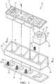
- a control panel 10 for a motor vehicle has a front face 12 with pictograms 16.
- Capacitive sensing elements 24 are provided to be arranged against the rear face 40 of the front face 12.
- the front face 12 is a single element covering the capacitive sensing elements 24.
- the front face 12 may be constituted a plurality of elements each covering one or more capacitive sensing elements 24.
- the control panel 10 also includes a printed circuit board 20 on which light sources 22 such as light-emitting diodes are disposed.
- the diodes, the capacitive sensing elements 24 and the pictograms 16 are aligned along a vertical axis V so that the light sources 22 can backlight the pictograms 16 through the capacitive sensing elements 24.
- Electrically conductive elastic elements 26 represented by metal springs are provided for electrically connecting the sensing elements 24 with the printed circuit board 20.
- the printed circuit board 20 comprises electrical connection 32 intended to be in electrical contact with the electrically conductive elastic elements 26.
- the pictograms 16 indicate control zones 14 on which a user can press in order to trigger a function of the vehicle.
- the pictograms 16 can be made by laser engravings on the front facade 12.
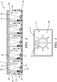
- Each capacitive sensing element 24 comprises a first portion forming a capacitive sensing pad 28 and a second portion forming a light guide 30.
- the detection plate 28 is adapted to be mounted adjacent to the rear face 40 of the front panel 12.
- the detection plate 28 is provided to enable the detection of the support of a user's finger on the zone 14 control vis-à-vis.
- the detection plate 28 is opaque and is provided with openings 29 allowing the light to backlight a pictogram 16 disposed on the front face 12, vis-à-vis the detection plate 28. These openings are generally of similar shape to the pictogram 16 and aligned with the pictogram 16 along the vertical axis V.
- the detection plate 28 may also be translucent so as to let the light.
- the detection pad 28 may diffuse light onto its surface.
- the capacitive sensing plate 28 is placed in a recess 39 of the rear face 40 of the front panel 12.
- the recess 39 brings the detection pad 28 closer to the control zone 14 so as to adjust the detection sensitivity of the panel
- the depth of the recess 39 makes it possible to size the capacitive detection sensitivity of the device.
- the detection element 24 may preferably be overmoulded with the front face 12, or glued into the recess 39.
- the overmolding makes it possible to dispense with a gluing step, the glue being able to reduce the capacitive detection sensitivity and which can be an obstacle to the diffusion of light through the detection plate 28 to the pictogram 16.
- the second portion of the capacitive sensing elements 24 guides the light beams 44 from the light sources 22 to the sensing pads 28 thereby forming the light guides 30.
- Each light guide 30 extends from the sensing pad 28 to the card 20.
- Circuit light guide 30 comprises at least one wall 38 forming a duct for the light beam 44. As shown, the light guide comprises four walls forming a hollow cylinder of rectangular base shape
- the duct may be formed of a cavity such as a hollow cylindrical body of circular base shape, for which a single cylindrical wall 38 surrounds the light beam 44.
- the detection plate 28 closes the cylindrical cavity.
- the wall 38 extending from the detection pad 28 to the printed circuit board 20 forms the light pipe.
- the free end 42 of the cylindrical wall 38 is the end of the wall opposite to the detection plate. The free end 42 is in electrical contact with the printed circuit board 20 via the electrically conductive elastic element 26.
- the conduit may be formed of several walls 38 extending from the detection plate 28 to the printed circuit board 20 allowing the light beam 44 to be directed essentially towards the detection plate 28.
- the internal walls of the channel reflect the light and do not let light scatter outside the duct.
- the capacitive sensing elements 24 are electrically conductive plastic parts. Each capacitive sensing element 24 is formed in one piece. Preferably, these are pieces made of plastic loaded with metal particles such as, for example, powder or flakes of aluminum, copper or zinc.
- the electrically conductive elastic element 26 makes it possible to electrically connect a free end 42 of the light guide 30 to the printed circuit board 20.
- the electrically conductive elastic element 26 makes it possible to overcome the tolerances of the assembly of the control panel 10, more particularly the tolerance of the distance separating the capacitive sensing element 24 from the printed circuit board 20.
- the electrically conductive elastic element 26 is also able to be fixed by soldering on the printed circuit board 20 on a circuit board. Electrical connection zone 32. It may be envisaged not to arrange electrically conductive elastic elements 26. In this case, a wall 38 of the light guide 30 of the detection element 24 has flexible and elastic properties. so to be in support on the electrical contact zone 32. It is also conceivable that the detection element does not have flexible and elastic properties when the assembly tolerances are perfectly mastered.
- the capacitive sensing elements 24 are spaced apart from each other.
- the distinct capacitive sensing elements 24 are not directly electrically connected to each other so that each sensing element 24 detects only the control associated with it.
- control panel 10 of the figure 1 also includes a housing 34.
- This housing 34 is provided to close the control panel 10.
- the housing 34 includes a peripheral edge 36 provided to surround the printed circuit board 20 and extending vertically to the front facade 12 so that the front face 12 can close the housing 34.
- the housing 34 also includes opaque walls 41 arranged on the printed circuit board 20 and disposed between the light sources 22 so as to block any light scattering from a source from light 22 to another.
- a pictogram 16 is backlit.
- the detection plate 28 arranged under the front panel 12 has been shown visible through the control zone 14.
- the pictogram 16 of the control zone 14 is above the surface of the control panel. detection 28.
- the detection plate 28 also allows a light diffusion so as to backlight the pictogram 16. Therefore, the advantage of the invention is to be able to use the entire surface of the detection plate 28 to diffuse the light towards the pictogram 16.
- the size of the pictogram 16 is limited only by the control zone 14 defined by the surface of the detection plate 28.
- the capacitive sensing element 24 as a guide to light 30 for the backlighting of the pictograms 16 solves a problem known from the prior art for which the capacitive sensing element 24 is a metal strip comprena and a portion adjacent to the front panel 12. This plate forms a metal capacitive sensing electrode.
- the part of the lamella adjacent to the front facade obstruction to the backlight so that the size of the pictogram 16 must be reduced on the front facade so that the light beam can backlight the pictogram.
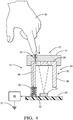
- a capacitive control button 13 comprises the detection zone 14 located on the front face 12, the capacitive sensing element 24 arranged adjacent to the front face 12 and the elastic metal element 26 in electrical connection between the printed circuit board 20 and the capacitive sensing element 24.
- a finger 50 of a user touches a control zone 14
- a capacitive coupling represented by the symbol of a capacitor 52
- detection 28 The pressing on a control zone 14 creates a flow or electrical signal 46 represented by the arrows, from the front face 12 to a control element 48 of the capacitive sensing element 24.
- the electrical signal 46 capacitively induced through the capacitive coupling is propagated towards an electrical mass 54 provided by the control element 48.
- the electrical signal 46 follows a path through the plate. detection piece, then through a wall 38 of the light guide 30 electrically connected to the printed circuit board 20.
- the electrical signal 46 passes through the electrically conductive elastic member 26 which routes the signal 46 to the zone
- the electrical connection zone 32 is electrically connected to the control element 48.
- the control element 48 may be a microcontroller whose port is configured to acquire the electrical signal 46.
- the electrical connection zone 32 is electrically connected to the control element 48. so that the system thus described functions as a capacitive sensor.
- the microcontroller 48 can electrically control the light source 22 so as to synchronize its activation or deactivation according to the detection or the non-detection of the support on the control zone 14.
- the control element 48 can also be any other type of control element for detecting the presence of the electrical signal 46 generated by a capacitive coupling.
Landscapes
- Engineering & Computer Science (AREA)
- Chemical & Material Sciences (AREA)
- Combustion & Propulsion (AREA)
- Transportation (AREA)
- Mechanical Engineering (AREA)
- Switches That Are Operated By Magnetic Or Electric Fields (AREA)
Abstract
Un panneau de commande pour véhicule automobile comprend une façade frontale (12) comportant au moins un pictogramme (16) indiquant une zone de commande (14); au moins un élément de détection capacitive (24) agencé contre la face arrière (40) de la façade frontale (12) et apposé en vis-à-vis du pictogramme (16); une carte à circuit imprimé (20); une source de lumière (22) montée sur la carte à circuit imprimé (20) et apte à produire un faisceau lumineux (44) de rétroéclairage vers le pictogramme. L'élément de détection capacitive (24) est une pièce plastique électriquement conductrice comprenant : une première partie formant une plaquette de détection (28) adjacente à la face arrière (40) de la façade frontale (12) apte à permettre une détection capacitive sur la zone de commande (14); une deuxième partie formant un guide de lumière (30) comprenant au moins une paroi (38) qui s'étend depuis la plaquette de détection (28) vers la carte à circuit imprimé (20) de manière à guider le faisceau lumineux (44) vers le pictogramme (16). L'élément de détection capacitive (24) est raccordé électriquement à la carte à circuit imprimé (20) par l'extrémité (42) de la paroi opposée à la plaquette de détection (28).A control panel for a motor vehicle comprises a front face (12) having at least one pictogram (16) indicating a control zone (14); at least one capacitive sensing element (24) arranged against the rear face (40) of the front face (12) and affixed opposite the pictogram (16); a printed circuit board (20); a light source (22) mounted on the printed circuit board (20) and adapted to produce a backlight light beam (44) to the pictogram. The capacitive sensing element (24) is an electrically conductive plastic part comprising: a first part forming a detection plate (28) adjacent to the rear face (40) of the front panel (12) adapted to allow capacitive detection on the control zone (14); a second portion forming a light guide (30) comprising at least one wall (38) extending from the detection board (28) to the printed circuit board (20) so as to guide the light beam (44) to the pictogram (16). The capacitive sensing element (24) is electrically connected to the printed circuit board (20) by the end (42) of the wall opposite the sensing plate (28).
Description
La présente invention concerne un panneau de commande automobile et plus particulièrement un panneau de commande rétroéclairé équipé de boutons capacitifs.The present invention relates to an automobile control panel and more particularly to a backlit control panel equipped with capacitive buttons.
Des dispositifs de commandes ou panneau de commande à boutons capacitifs sont connus de l'art antérieur. De tels dispositifs comprennent généralement une façade frontale transparente peinte sur sa face arrière et présentant une pluralité de pictogrammes fonctionnels indiquant des zones spécifiques de commandes. Un film capacitif est apposé contre la face arrière de la façade frontale de sorte à ce que les zones de commandes forment des boutons de commandes capacitifs. Une carte électronique à circuit imprimé est reliée électriquement au film capacitif et comporte des moyens de contrôle du film capacitif. Pour assurer le rétroéclairage des pictogrammes, des diodes électroluminescentes sont agencées sur la carte à circuits imprimés. Généralement une entretoise est intercalée entre le film capacitif et la carte électronique à circuit imprimé, dans laquelle sont agencées des ouvertures rectangulaires disposées en regard des pictogrammes. Des montants s'étendent vers l'arrière depuis le pourtour de ces ouvertures, avec leurs extrémités libres qui reposent contre la carte électronique en entourant chacune des diodes électroluminescentes. Ces montants permettent de compartimenter le flux lumineux produits par les diodes et d'éviter la dispersion de lumière dans l'ensemble du panneau de commande.Control devices or control panel with capacitive buttons are known from the prior art. Such devices generally comprise a transparent front facade painted on its rear face and having a plurality of functional pictograms indicating specific areas of commands. A capacitive film is affixed against the rear face of the front facade so that the control areas form capacitive control knobs. An electronic printed circuit board is electrically connected to the capacitive film and comprises means for controlling the capacitive film. To ensure the backlighting of the pictograms, light-emitting diodes are arranged on the printed circuit board. Generally a spacer is interposed between the capacitive film and the printed circuit board, in which are arranged rectangular openings arranged opposite the pictograms. Posts extend rearwardly from the periphery of these openings, with their free ends resting against the electronic card by surrounding each of the light emitting diodes. These amounts make it possible to compartmentalize the luminous flux produced by the diodes and to avoid the scattering of light throughout the control panel.
Ce type de dispositif de commande à boutons capacitifs demande un assemblage complexe de différentes pièces de technologie différentes, notamment l'assemblage de pièces plastiques telles que la façade frontale, avec un film capacitif. Le film capacitif représente également une contrainte pour le rétroéclairage, notamment par ses propriétés de propagation de la lumière.This type of capacitive button control device requires a complex assembly of different pieces of different technology, including the assembly of plastic parts such as the front face, with a capacitive film. The capacitive film also represents a constraint for the backlight, in particular by its light propagation properties.
Le document
Il est donc important de proposer une solution nouvelle résolvant ces problèmes.It is therefore important to propose a new solution solving these problems.
Un panneau de commande pour véhicule automobile comprend une façade frontale comportant au moins un pictogramme indiquant une zone de commande; au moins un élément de détection capacitive agencé contre la face arrière de la façade frontale et apposé en vis-à-vis du pictogramme; une carte à circuit imprimé; une source de lumière montée sur la carte à circuit imprimé et apte à produire un faisceau lumineux de rétroéclairage vers le pictogramme. L'élément de détection capacitive est une pièce plastique électriquement conductrice comprenant: une première partie formant une plaquette de détection adjacente à la face arrière de la façade frontale apte à permettre une détection capacitive sur la zone de commande; une deuxième partie formant un guide de lumière comprenant au moins une paroi qui s'étend depuis la plaquette de détection vers la carte à circuit imprimé de manière à guider le faisceau lumineux vers le pictogramme. L'élément de détection capacitive est raccordé électriquement à la carte à circuit imprimé par l'extrémité de la paroi opposée à la plaquette de détection.A control panel for a motor vehicle comprises a front facade comprising at least one pictogram indicating a control zone; at least one capacitive sensing element arranged against the rear face of the front facade and affixed vis-à-vis the pictogram; a printed circuit board; a light source mounted on the printed circuit board and capable of producing a backlighting light beam towards the pictogram. The capacitive sensing element is an electrically conductive plastic part comprising: a first portion forming a detection pad adjacent to the rear face of the front panel capable of enabling capacitive sensing on the control area; a second portion forming a light guide comprising at least one wall extending from the detection board to the printed circuit board so as to guide the light beam towards the pictogram. The capacitive sensing element is electrically connected to the printed circuit board by the end of the wall opposite the sensing plate.
L'élément de détection capacitive peut être une seule pièce surmoulée avec la façade frontale. L'élément de détection capacitive peut être une pièce plastique chargée de particules métalliques. Le guide de lumière peut être un conduit de lumière apte à diriger le faisceau lumineux vers le pictogramme. La plaquette de détection peut être opaque et peut comporter au moins une ouverture en vis-à-vis du pictogramme apte à laisser passer la lumière vers le pictogramme. La face arrière de la façade frontale comprend un renfoncement dans lequel la plaquette de détection est agencée. Une pièce élastique électriquement conductrice, apte à être maintenue en appui sur la zone de raccordement électrique de la carte à circuit imprimé, peut être agencée électriquement en contact entre l'extrémité de la paroi opposée à la plaquette de détection et une zone de raccordement électrique de la carte à circuit imprimé. Le panneau de commande peut comporter une pluralité d'éléments de détection capacitive distincts associés à une pluralité de boutons de commande capacitifs distincts.The capacitive sensing element may be a single piece overmolded with the front face. The capacitive sensing element may be a plastic part loaded with metal particles. The light guide may be a light pipe adapted to direct the light beam towards the pictogram. The detection plate may be opaque and may include at least one opening vis-à-vis the pictogram able to let the light to the pictogram. The rear face of the front facade comprises a recess in which the detection plate is arranged. An electrically conductive elastic part, capable of being held in abutment on the electrical connection zone of the printed circuit board, can be arranged electrically in contact between the end of the wall opposite the detection plate and an electrical connection zone. of the printed circuit board. The control panel may include a plurality of distinct capacitive sensing elements associated with a plurality of distinct capacitive control buttons.
D'autres caractéristiques, buts et avantages de l'invention apparaîtront à la lecture de la description détaillée qui va suivre, et en regard des dessins annexés, donnés à titre d'exemple non limitatif et sur lesquels:
- La
figure 1 est une vue en perspective d'un panneau de commande pour véhicule automobile selon l'invention. - La
figure 2 est une vue schématique en coupe axiale selon le plan 2-2 du panneau de commande de lafigure 1 . - La
figure 3 est une vue de dessus qui représente schématiquement une zone de commande illuminée du panneau de commande de lafigure 1 . - La
figure 4 est une vue similaire à celle de lafigure 2 qui illustre l'actionnement d'un bouton capacitif du panneau de commande de lafigure 1 .
- The
figure 1 is a perspective view of a control panel for a motor vehicle according to the invention. - The
figure 2 is a schematic view in axial section along the plane 2-2 of the control panel of thefigure 1 . - The
figure 3 is a top view which schematically shows an illuminated control area of the control panel of thefigure 1 . - The
figure 4 is a view similar to that of thefigure 2 which illustrates the actuation of a capacitive button on the control panel of thefigure 1 .
Selon la
Les pictogrammes 16 indiquent des zones de commande 14 sur lesquelles un utilisateur peut appuyer afin de déclencher une fonction du véhicule. Les pictogrammes 16 peuvent être réalisés par gravures laser sur la façade frontale 12.The
Chaque élément de détection capacitif 24 comprend une première partie formant une plaquette de détection capacitive 28 et une deuxième partie formant un guide de lumière 30.Each
La plaquette de détection 28 est adaptée pour être montée de manière adjacente à la face arrière 40 de la façade frontale 12. La plaquette de détection 28 est prévue pour permettre la détection de l'appui d'un doigt d'un utilisateur sur la zone de commande 14 en vis-à-vis. La plaquette de détection 28 est opaque et est munie d'ouvertures 29 permettant à la lumière de rétroéclairer un pictogramme 16 disposé sur la façade frontale 12, en vis-à-vis de la plaquette de détection 28. Ces ouvertures sont généralement de forme similaire au pictogramme 16 et alignées avec le pictogramme 16 suivant l'axe vertical V. La plaquette de détection 28 peut également être translucide de sorte à laisser passer la lumière. Optionnellement, la plaquette de détection 28 peut diffuser la lumière sur sa surface.The
La plaquette de détection capacitive 28 est placée dans un renfoncement 39 de la face arrière 40 de la façade frontale 12. Le renfoncement 39 permet de rapprocher la plaquette de détection 28 de la zone de commande 14 de sorte à ajuster la sensibilité de détection du panneau de commande 10. En d'autre terme, la profondeur du renfoncement 39 permet de dimensionner la sensibilité de détection capacitive du dispositif. L'élément de détection 24 peut être de préférence surmoulé avec la façade frontale 12, ou collé dans le renfoncement 39. Le surmoulage permet de s'affranchir d'une étape de collage, la colle pouvant réduire la sensibilité de détection capacitive et pouvant être un obstacle à la diffusion de la lumière au travers de la plaquette de détection 28 vers le pictogramme 16.The
La deuxième partie des éléments de détection capacitive 24 guide les faisceaux lumineux 44 des sources de lumière 22 vers les plaquettes de détection 28 formant ainsi les guides de lumière 30. Chaque guide de lumière 30 s'étend depuis la plaquette de détection 28 vers la carte à circuit imprimé 20.Chaque guide de lumière 30 comprend au moins une paroi 38 formant un conduit pour le faisceau lumineux 44. Tel que représenté, le guide de lumière comprend quatre parois formant un cylindre creux de forme de base rectangulaireThe second portion of the
Alternativement le conduit peut être formé d'une cavité tel un corps cylindrique creux de forme de base circulaire, pour laquelle une seule paroi cylindrique 38 entoure le faisceau lumineux 44. La plaquette de détection 28 bouche la cavité cylindrique. La paroi 38 s'étendant depuis la plaquette de détection 28 vers la carte à circuit imprimé 20 forme le conduit de lumière. L'extrémité libre 42 de la paroi cylindrique 38 est l'extrémité de la paroi opposée à la plaquette de détection. L'extrémité libre 42 est en contact électrique avec la carte à circuit imprimé 20 par l'intermédiaire de l'élément élastique électriquement conducteur 26.Alternatively the duct may be formed of a cavity such as a hollow cylindrical body of circular base shape, for which a single
Alternativement, le conduit peut être formé de plusieurs parois 38 s'étendant depuis la plaquette de détection 28 vers la carte à circuit imprimé 20 permettant au faisceau lumineux 44 de se diriger essentiellement vers la plaquette de détection 28. Les parois interne du conduit réfléchissent la lumière et ne laissent pas la lumière se disperser en dehors du conduit.Alternatively, the conduit may be formed of
Les éléments de détection capacitive 24 sont des pièces plastiques électriquement conductrices. Chaque élément de détection capacitif 24 est formé d'une seule pièce. De préférence ce sont des pièces formées de plastique chargée en particules métalliques telles que par exemple de la poudre ou des paillettes d'aluminium, de cuivre ou de zinc.The
L'élément élastique électriquement conducteur 26 permet de relier électriquement une extrémité libre 42 du guide de lumière 30 à la carte à circuit imprimé 20. L'élément élastique électriquement conducteur 26 permet de s'affranchir des tolérances de l'assemblage du panneau de commande 10, plus particulièrement de la tolérance de la distance séparant l'élément de détection capacitive 24 avec la carte à circuit imprimé 20. L'élément élastique électriquement conducteur 26 est également apte à être fixé par soudure sur la carte à circuit imprimé 20 sur une zone de raccordement électrique 32. Il peut être envisagé de ne pas agencer d'éléments élastiques électriquement conducteurs 26. Dans ce cas de figure, une paroi 38 du guide de lumière 30 de l'élément de détection 24 a des propriétés souple et élastique de sorte à être en appui sur la zone de contact électrique 32. Il est également envisageable que l'élément de détection n'ai pas de propriétés souple et élastique lorsque les tolérances d'assemblages sont parfaitement maitrisées.The electrically conductive
Comme représenté sur la
Bien que cela ne soit pas indispensable à l'invention, le panneau de commande 10 de la
Selon la
Selon la
Optionnellement, le microcontrôleur 48 peut piloter électriquement la source de lumière 22 de sorte à synchroniser son activation ou sa désactivation en fonction de la détection ou de la non détection de l'appui sur la zone de commande 14. L'élément de contrôle 48 peut également être tout autre type d'élément de contrôle permettant de détecter la présence du signal électrique 46 généré par un couplage capacitif.Optionally, the
Claims (7)
une façade frontale (12) comportant au moins un pictogramme (16) indiquant une zone de commande (14);
au moins un élément de détection capacitive (24) agencé contre la face arrière (40) de la façade frontale (12) et apposé en vis-à-vis du pictogramme (16);
une carte à circuit imprimé (20);
une source de lumière (22) montée sur la carte à circuit imprimé (20) et apte à produire un faisceau lumineux (44) de rétroéclairage vers le pictogramme ;
caractérisé en ce que
l'élément de détection capacitive (24) est une pièce plastique électriquement conductrice comprenant :
a front face (12) having at least one pictogram (16) indicating a control zone (14);
at least one capacitive sensing element (24) arranged against the rear face (40) of the front face (12) and affixed opposite the pictogram (16);
a printed circuit board (20);
a light source (22) mounted on the printed circuit board (20) and adapted to produce a backlight light beam (44) to the pictogram;
characterized in that
the capacitive sensing element (24) is an electrically conductive plastic part comprising:
Applications Claiming Priority (1)
| Application Number | Priority Date | Filing Date | Title |
|---|---|---|---|
| FR1653969A FR3050698B1 (en) | 2016-05-02 | 2016-05-02 | CONTROL PANEL FOR MOTOR VEHICLE |
Publications (1)
| Publication Number | Publication Date |
|---|---|
| EP3241702A1 true EP3241702A1 (en) | 2017-11-08 |
Family
ID=56119678
Family Applications (1)
| Application Number | Title | Priority Date | Filing Date |
|---|---|---|---|
| EP17168733.8A Withdrawn EP3241702A1 (en) | 2016-05-02 | 2017-04-28 | Control panel for a motor vehicle |
Country Status (2)
| Country | Link |
|---|---|
| EP (1) | EP3241702A1 (en) |
| FR (1) | FR3050698B1 (en) |
Cited By (3)
| Publication number | Priority date | Publication date | Assignee | Title |
|---|---|---|---|---|
| WO2019114981A1 (en) * | 2017-12-15 | 2019-06-20 | Lisa Dräxlmaier GmbH | Line lighting with integrated operating element |
| CN115407902A (en) * | 2021-05-26 | 2022-11-29 | Bsh家用电器有限公司 | Display and operating device |
| IT202200012482A1 (en) * | 2022-06-13 | 2023-12-13 | Bitron Spa | KEY FOR SWITCH DEVICES, METHOD OF CONSTRUCTION OF SUCH KEY AND RELATED SWITCH DEVICE |
Citations (3)
| Publication number | Priority date | Publication date | Assignee | Title |
|---|---|---|---|---|
| US5917165A (en) | 1997-02-17 | 1999-06-29 | E.G.O. Elektro-Geraetebau Gmbh | Touch switch with flexible, intermediate conductive spacer as sensor button |
| EP2341624A1 (en) * | 2009-12-23 | 2011-07-06 | Diehl AKO Stiftung & Co. KG | Capacitive contact switch |
| EP2355356A1 (en) | 2010-02-04 | 2011-08-10 | Diehl AKO Stiftung & Co. KG | Capacitative touch and/or proximity sensor |
-
2016
- 2016-05-02 FR FR1653969A patent/FR3050698B1/en active Active
-
2017
- 2017-04-28 EP EP17168733.8A patent/EP3241702A1/en not_active Withdrawn
Patent Citations (3)
| Publication number | Priority date | Publication date | Assignee | Title |
|---|---|---|---|---|
| US5917165A (en) | 1997-02-17 | 1999-06-29 | E.G.O. Elektro-Geraetebau Gmbh | Touch switch with flexible, intermediate conductive spacer as sensor button |
| EP2341624A1 (en) * | 2009-12-23 | 2011-07-06 | Diehl AKO Stiftung & Co. KG | Capacitive contact switch |
| EP2355356A1 (en) | 2010-02-04 | 2011-08-10 | Diehl AKO Stiftung & Co. KG | Capacitative touch and/or proximity sensor |
Cited By (3)
| Publication number | Priority date | Publication date | Assignee | Title |
|---|---|---|---|---|
| WO2019114981A1 (en) * | 2017-12-15 | 2019-06-20 | Lisa Dräxlmaier GmbH | Line lighting with integrated operating element |
| CN115407902A (en) * | 2021-05-26 | 2022-11-29 | Bsh家用电器有限公司 | Display and operating device |
| IT202200012482A1 (en) * | 2022-06-13 | 2023-12-13 | Bitron Spa | KEY FOR SWITCH DEVICES, METHOD OF CONSTRUCTION OF SUCH KEY AND RELATED SWITCH DEVICE |
Also Published As
| Publication number | Publication date |
|---|---|
| FR3050698B1 (en) | 2019-06-14 |
| FR3050698A1 (en) | 2017-11-03 |
Similar Documents
| Publication | Publication Date | Title |
|---|---|---|
| EP3290253B1 (en) | Control panel for a motor vehicle | |
| FR3050043B1 (en) | COMPOSITE INTERFACE DEVICE WITH TOUCH SCREEN AND CONTROL BUTTON | |
| EP2109869B1 (en) | Electric control device | |
| EP3404682B1 (en) | Operation assembly by sliding contact of a control panel for a motor vehicle | |
| WO2012175369A1 (en) | Control panel comprising a resistive-type backlit key | |
| FR3050698B1 (en) | CONTROL PANEL FOR MOTOR VEHICLE | |
| EP3404506B1 (en) | Control panel for a motor vehicle | |
| CN105745120A (en) | Vehicle lamp | |
| CN109792243B (en) | Layer composite structure for providing operating elements for household appliances | |
| WO2018078175A1 (en) | Backlit capacitive control interface for motor vehicle | |
| FR3016563A1 (en) | TOUCH CONTROL DEVICE FOR MOTOR VEHICLE DASHBOARD | |
| WO2016150572A1 (en) | Movable or deformable touch pad system forming a human-machine interface suitable for a vehicle steering wheel | |
| EP2637886A1 (en) | Electronic control panel for motor vehicle | |
| JP2014085456A (en) | Decorative panel | |
| FR3091505A1 (en) | Upholstery element comprising a backlit touch control device | |
| EP2845771A1 (en) | Structural assembly of a motor vehicle | |
| FR3126516A1 (en) | Vehicle user interface panel and method of making such a user interface panel | |
| FR3046658A1 (en) | PROGRESSIVE IGNITION LIGHTING MODULE FOR MOTOR VEHICLE | |
| EP3059660A1 (en) | Interaction interface including a touch screen, a proximity detector and a protective plate | |
| FR3049914B1 (en) | CONTROL DEVICE FOR VEHICLE AND METHOD FOR REALIZING CONTROL DEVICE | |
| FR3039792A1 (en) | CONTROL DEVICE | |
| EP2844956B1 (en) | Light guide element and cover, dashboard and method of fabrication of a decorative element | |
| WO2016156683A1 (en) | Capacitive approach-detecting method and device and user interface | |
| EP4722040A1 (en) | Trim element comprising a backlit logo and a radar | |
| US10408424B2 (en) | Light guiding device |
Legal Events
| Date | Code | Title | Description |
|---|---|---|---|
| PUAI | Public reference made under article 153(3) epc to a published international application that has entered the european phase |
Free format text: ORIGINAL CODE: 0009012 |
|
| AK | Designated contracting states |
Kind code of ref document: A1 Designated state(s): AL AT BE BG CH CY CZ DE DK EE ES FI FR GB GR HR HU IE IS IT LI LT LU LV MC MK MT NL NO PL PT RO RS SE SI SK SM TR |
|
| AX | Request for extension of the european patent |
Extension state: BA ME |
|
| STAA | Information on the status of an ep patent application or granted ep patent |
Free format text: STATUS: THE APPLICATION IS DEEMED TO BE WITHDRAWN |
|
| 18D | Application deemed to be withdrawn |
Effective date: 20180509 |