EP3241716B1 - Fahrwerk für ein schienenfahrzeug - Google Patents
Fahrwerk für ein schienenfahrzeug Download PDFInfo
- Publication number
- EP3241716B1 EP3241716B1 EP17164979.1A EP17164979A EP3241716B1 EP 3241716 B1 EP3241716 B1 EP 3241716B1 EP 17164979 A EP17164979 A EP 17164979A EP 3241716 B1 EP3241716 B1 EP 3241716B1
- Authority
- EP
- European Patent Office
- Prior art keywords
- bogie
- actuator unit
- chassis
- actuator
- swing arm
- Prior art date
- Legal status (The legal status is an assumption and is not a legal conclusion. Google has not performed a legal analysis and makes no representation as to the accuracy of the status listed.)
- Active
Links
Images

Classifications
-
- B—PERFORMING OPERATIONS; TRANSPORTING
- B61—RAILWAYS
- B61F—RAIL VEHICLE SUSPENSIONS, e.g. UNDERFRAMES, BOGIES OR ARRANGEMENTS OF WHEEL AXLES; RAIL VEHICLES FOR USE ON TRACKS OF DIFFERENT WIDTH; PREVENTING DERAILING OF RAIL VEHICLES; WHEEL GUARDS, OBSTRUCTION REMOVERS OR THE LIKE FOR RAIL VEHICLES
- B61F5/00—Constructional details of bogies; Connections between bogies and vehicle underframes; Arrangements or devices for adjusting or allowing self-adjustment of wheel axles or bogies when rounding curves
- B61F5/38—Arrangements or devices for adjusting or allowing self- adjustment of wheel axles or bogies when rounding curves, e.g. sliding axles, swinging axles
- B61F5/386—Arrangements or devices for adjusting or allowing self- adjustment of wheel axles or bogies when rounding curves, e.g. sliding axles, swinging axles fluid actuated
Definitions
- the invention relates to a chassis for a rail vehicle, comprising at least one landing gear frame, at least one pair of wheels or at least one wheelset and with an active wheel control or Radsatz facedung having at least one actuator and at least one designed as a hydraulic jack elastic bearing.
- Landing gears for rail vehicles must have a high driving safety. This can be improved, for example, by the arrangement of an active wheel control or wheel set control.
- the targeted placement of wheels or wheelsets by actively rotating the same about their vertical axes is used in a known manner to prevent unstable driving conditions.
- the ride comfort is increased by avoiding disturbing vibrations in a rail vehicle.
- the active wheel control or Radsatz tortureung causes a reduction in the wear of wheels and rails.
- An installation of an active wheel control or wheelset control brings with it the requirement to have to arrange additional components (eg actuators) in the chassis. This often leads to conflicts with limited space budgets. Furthermore, these additional components must be protected from environmental influences.
- the prior art describes, for example, the DE 10 2009 041 110 A1 fluidic actuators and their arrangement in a chassis for rail vehicles.
- the interaction of two actuators is shown, which among other things adjust the steering angle of wheelsets about their vertical axes.
- a first actuator impresses a first wheel set quasi-static, a second actuator a second wheel set dynamic steering angle deflections.
- the actuators are connected via handlebars with the wheelsets.
- About one in the DE 10 2009 041 110 A1 not shown coupling the wheelsets can be transferred to the wheel set imprinted adjusting movement in the other wheelset.
- Said approach has in its known form the disadvantage that the actuators are exposed to the surroundings of the chassis and exposed to the influence of environmental conditions such as weather, rockfall, vandalism, etc. are exposed.
- the EP 0 870 664 B1 shows a method and a device for wheelset management of rail vehicles.
- a device is shown in which the setting angle of wheelsets is generated by a two-chamber fluid bushing.
- a swing arm connects the wheel set with a chassis frame.
- the fluid sleeve is disposed between the swing arm and the chassis frame. Their chambers are mutually acted upon by fluid via corresponding connections, whereby a relative movement between the swing arm and the chassis frame is generated.
- an embodiment is shown with a double spring leaf-Radsatzscher for the change of Radsatz adjustment angles.
- the mentioned approach has in its known form the disadvantage that the embodiments shown exposed to the environment of the chassis and the influence of environmental conditions such as weather, rockfall, vandalism, etc. are exposed or that provided their own components for the encapsulation of the facilities Need to become. Furthermore, the devices shown are less suitable for the generation of larger wheelset adjustment angle, as they are to be set, for example, for a bow travel of the rail vehicle, but rather for the generation of small wheelset adjustment angle for the compensation of dynamic disturbances.
- this object is achieved with a chassis according to claim 1.
- a chassis according to claim 1 By this measure, the advantage of a low utilization of a limited space budget is achieved.
- This is particularly advantageous for retrofits of rail vehicles with active wheel controls or wheelset controls, for which hardly any additional space can be created.
- a swing arm without actuator unit can be replaced by a swing arm, within which an actuator unit is arranged.
- the arrangement of the actuator within a component of the chassis continues to provide a favorable sheathing of the actuator by this component achieved.
- the actuator unit is well protected against environmental influences such as weather, rockfall, vandalism, etc.
- Separate means for encapsulating the actuator unit can be dispensed with.
- the at least one actuator unit is designed as a pneumatic actuator.
- the pneumatic actuator can be fed from the compressed air system of the vehicle, as it is used for brake systems, for example.
- the presence of air procurement equipment in rail vehicles is common. Additional units can therefore be dispensed with, whereby a cost advantage is achieved.
- a separation and rebuilding of the pneumatic actuator in maintenance are possible quickly and easily.
- air as the medium of the pneumatic actuator is not flammable, not environmentally hazardous and leads to leaks in no pollution.
- the actuator unit has at least one measuring device for the determination of information about kinetic states of the chassis.
- the measuring device may, for example, be connected via line paths to a control device of a wheel or wheel set controller.
- the actuator unit has a first connection and a second connection, which are separably connected to supply lines via quick-release couplings.
- the mechanical force translator By the mechanical force translator a translation of the force generated by the actuator unit and thus a favorable flexibility in the dimensioning of the actuator unit is achieved.
- Standard components can be provided; adaptation to a chassis-specific actuating force level can take place via a corresponding dimensioning and arrangement of the mechanical force translator.
- the mechanical force translator enables the bridging of a local distance between the installation location of the actuator unit, a chassis frame and pairs of wheels or wheelsets. This results in an advantageous flexibility for the arrangement of the actuator unit in the chassis.
- the mechanical power translator is disposed within a component of the landing gear. This results in a first favorable sheathing, which protects the mechanical force translator from environmental influences. On separate means for its encapsulation can be omitted. Secondly, this provides the advantage of a cheap use of a limited space budget.
- the invention will be explained in more detail by means of exemplary embodiments.
- FIG. 1 Section of a first, exemplary variant of a chassis according to the invention shown in side view comprises a section of a chassis frame 1 and a pair of wheels 2, which rests on a track 11. Furthermore, a wheel bearing 6, a swing arm 3 in a sectional view and a wheel bearing housing 7 are shown.
- the pair of wheels 2 comprises two wheels, which are connected to each other via a mechanical coupling, not shown.
- the chassis frame 1 is part of a primary sprung plane of the chassis and the pair of wheels 2, the wheel bearing 6, the swing arm 3 and the wheel bearing housing 7 belong to a non-sprung plane of the chassis.
- the swing arm 3 is connected to the wheel bearing housing 7 and supported rotatably together about a wheel axle 8.
- a passive elastic bearing 5 with frequency and amplitude-dependent static and increased dynamic stiffness is provided for generating a dynamic stiffness for guiding the pair of wheels 2, which is connected to the swing arm 3.
- the elastic bearing 5 is designed as a cylindrical, hydraulic bush whose circular base is arranged parallel to a plane spanned by the directions of a chassis longitudinal axis 9 and a landing gear axle 10 plane.
- the hydraulic sleeve has a stabilizing, resilient and damping effect primarily in the plane of its base, ie in the direction of the chassis longitudinally and 9 in the direction of the chassis high 10.
- a stabilization of the primary sprung plane and the non-sprung plane of the chassis is a vibration-mechanical decoupling the two levels achieved from each other.
- An actuator unit 4 is connected in parallel to the elastic bearing 5 with respect to its mechanical action. It is arranged with respect to their position in such a way that the force generated by it acts in parallel with respect to the direction of the chassis longitudinal axis 9.
- the actuator unit 4 is designed as a pneumatic actuator or as a double-acting pneumatic cylinder and comprises a cylindrical piston 12 with a piston seal, not shown, and a piston rod 13. These components are guided within the swing arm 3.
- a cylindrical recess is formed, which acts as a housing 14 of the piston 12 and the piston rod 13.
- Via a first port 19 the first air chamber 17 is supplied with compressed air, via a second port 20, the second air chamber 18th
- the piston seal prevents inadvertent pressure equalization between the first air chamber 17 and the second air chamber 18th
- the housing 14 is sealed against its surroundings.
- a pressure compensation can take place exclusively via the first port 19 and the second port 20.
- devices for processing and promotion of compressed air and for a control or regulation of the air pressure eg compressors, lines, valves, control devices, etc.
- the first terminal 19 and the second terminal 20 are separably connected via not shown quick couplings with supply lines, also not shown.
- the piston rod 13 With the piston 12, the piston rod 13 is connected. This emerges from the housing 14 via a recess on the second end face 26.
- the recess has a seal and a scraper ring, firstly to prevent inadvertent pressure equalization of the second air chamber 18 with its surroundings, and secondly, ingress of dirt into the second air chamber 18.
- the piston rod 13 has a first stop buffer 30, extends in the direction of the chassis longitudinal axis 9 and contacted via the first stop buffer 30, a second stop buffer 31 which is mounted on a cantilever 24.
- the cantilever 24 is connected to the chassis frame 1.
- the contours of the first stop buffer 30 and the second stop buffer 31 are circular arc-shaped, to allow a rolling of the piston rod 13 on the cantilever 24 and thus a compensation of relative movements between the non-sprung and the primary sprung plane of the chassis.
- an actuator force 22 is formed which, owing to the arrangement of the actuator unit 4 with respect to its position, in the direction of the chassis longitudinal axis 9 runs. Both the extension and the retraction movement of the piston 12 are controlled by means of compressed air and the actuator force 22 formed.
- the actuator unit 4 and has a measuring device, not shown, for the determination of information about kinetic states of the chassis. This is connected via lines not shown with a control device also not shown a wheel or wheelset.
- Fig. 2 shows a side view of a second, exemplary embodiment of a chassis according to the invention, wherein a section of a chassis frame 1, a pair of wheels 2 on a track 11, a wheel bearing 6 and a wheel bearing housing 7 are shown. Furthermore, a swing arm 3 is shown in sectional view, which is connected to the wheel bearing housing 7 and is rotatably mounted together with this about a wheel axle 8.
- the pair of wheels 2 comprises two wheels, which are connected to each other via a mechanical coupling, not shown.
- a passive elastic bearing 5 with frequency and amplitude-dependent static and increased dynamic stiffness is provided for generating a dynamic stiffness for guiding the pair of wheels 2, which is designed as a hydraulic jack and connected to the swing arm 3.
- an actuator unit 4 is arranged within the swing arm 3. It is designed as a pneumatic actuator or as a double-acting pneumatic cylinder.
- the actuator unit 4 has a piston 12 with a first piston surface 15 and a second piston surface 16 and a piston rod 13.
- a formed cylindrical recess which acts as a housing 14 of the actuator 4.
- the housing 14 forms, together with the first piston surface 15, a first air chamber 17 and, together with the second piston surface 16, a second air chamber 18.
- the first air chamber 17 is sealed against the second air chamber 18 to prevent inadvertent pressure equalization between these two chambers.
- a first terminal 19 is provided, on a second end face 26 of the housing 14, a second port 20.
- the first air chamber 17 is supplied with compressed air, via the second port 20, the second air chamber 18th
- devices for processing and promotion of compressed air and for a control or regulation of the air pressure eg compressors, lines, valves, control devices, etc.
- the first terminal 19 and the second terminal 20 are separably connected via not shown quick couplings with supply lines, also not shown.
- the actuator unit 4 is sealed against the swing arm 3 in order to avoid unintentional pressure compensation operations.
- a wedge 27 is connected, which, disposed within the swing arm 3, a roller 28 touches, which is rotatably mounted on a cantilever 24.
- the cantilever 24 is connected to the chassis frame 1.
- the wedge 27 and the roller 28 are components of a mechanical force translator 29.
- This solution is advantageous.
- force translator 29 with cams, slotted guides are conceivable.
- the inner contour of the swing arm 3 is designed accordingly.
- the swing arm 3 is sealed from the environment to prevent ingress of dirt.
- an actuator force 22 By acting on the first piston surface 15 with compressed air, an actuator force 22 is formed, which moves the piston 12, the piston rod 13 and the wedge 27 vertically upward and loads the roller 28.
- the Aktuatorkraft 22 is increased and changed in their direction of action on the contact between the wedge 27 and the roller 28 according to the known wedge principle. Consequently acts on the roller 28, and on the cantilever 24 on the chassis frame 1, a horizontal translator force 23rd against the translator force 23 acts a restoring force due to the rigidity of the elastic bearing. 5
- a pressurization of the second piston surface 16 with compressed air leads to a movement of said components vertically downwards and to a relief of the roller 28th
- the restoring force of the elastic bearing 5 causes the contact between the roller 28 and the wedge 27 at any time, so even when the roller 28, remains upright. Due to the translator force 23, a relative movement between the swing arm 3 and the chassis frame 1 is generated and thereby made an adjustment of position and position of the pair of wheels 2. As a result, the setting task of the actuator unit 4 with respect to the pair of wheels 2 is performed.
- the actuator unit 4 and the power booster 29 each have a, not shown measuring device for the determination of information about kinetic states of the chassis. These are connected via lines not shown with a control device also not shown a wheel or wheelset.
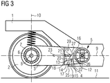
- FIG. 3 shows Fig. 3 an embodiment variant in which an actuator unit 4 is arranged vertically within a chassis frame 1.
- the actuator unit 4 is designed as a double-acting pneumatic cylinder, which has a first air chamber 17 and a second air chamber 18.
- the first air chamber 17 is supplied via a first port 19, the second air chamber 18 via a second port 20 with compressed air.
- the force acting on a piston 12 compressed air generates a vertical actuator force 22, which is transmitted to a piston rod 13 and a wedge 27.
- the piston 12 moves in a cylindrical recess in the chassis frame 1, which acts as a housing 14 of the actuator 4 and is sealed against their environment.
- the actuator force 22 is translated via the wedge 27 and a roller 28 into a horizontal translator force 23.
- the wedge 27 and the roller 28 are components of a mechanical force translator 29.
- the horizontal translator force 23 acts on the swing arm 3 via the roller 28, which is rotatably mounted on a cast rib 21 of the swing arm 3. Due to the effect of the translator force 23 and a relative movement between the swing arm 3 and the chassis frame 1, an adjustment of position and position of a pair of wheels 2 is made. As a result, the setting task of the actuator unit 4 with respect to the pair of wheels 2 is performed.
- FIG. 3 shown principle those embodiments that in Fig. 1 and Fig. 2 are shown.
- Fig. 1, Fig. 2 and Fig. 3 shown use of wheel bearings 6 and wheel bearing housings 7 is exemplary. Arrangements of wheelsets and wheelset bearing housings are also possible according to the invention.
- the adjusting movements of the individual actuator units 4 are coordinated with one another via corresponding control or regulating devices in order to generate tangential positions with respect to a track curve to be traveled, for example for all wheels in the chassis.
Landscapes
- Engineering & Computer Science (AREA)
- Mechanical Engineering (AREA)
- Vehicle Body Suspensions (AREA)
Description
- Die Erfindung betrifft ein Fahrwerk für ein Schienenfahrzeug, mit zumindest einem Fahrwerksrahmen, zumindest einem Räderpaar bzw. zumindest einem Radsatz sowie mit einer aktiven Radsteuerung bzw. Radsatzsteuerung, die zumindest eine Aktuatoreinheit und zumindest ein als hydraulische Buchse ausgeführtes Elastiklager aufweist.
- Fahrwerke für Schienenfahrzeuge müssen eine hohe Fahrsicherheit aufweisen. Diese kann beispielsweise durch die Anordnung einer aktiven Radsteuerung bzw. Radsatzsteuerung verbessert werden. Das gezielte Stellen von Rädern oder Radsätzen durch aktive Verdrehung derselben um deren Hochachsen dient in bekannter Weise dazu, instabile Fahrzustände zu verhindern.
Ferner wird dadurch der Fahrkomfort durch Vermeidung störender Schwingungen in einem Schienenfahrzeug erhöht. Außerdem bewirkt die aktive Radsteuerung bzw. Radsatzsteuerung eine Verminderung des Verschleißes von Rädern und Schienen.
Ein Einbau einer aktiven Radsteuerung bzw. Radsatzsteuerung bringt die Erfordernis mit sich, zusätzliche Komponenten (z.B. Aktuatoren) im Fahrwerk anordnen zu müssen. Dies führt bei begrenzten Bauraumbudgets häufig zu Konflikten. Weiterhin müssen diese zusätzlichen Komponenten vor Umgebungseinflüssen geschützt werden. - Nach dem Stand der Technik beschreibt beispielsweise die
DE 10 2009 041 110 A1 fluidische Aktuatoren und deren Anordnung in einem Fahrwerk für Schienenfahrzeuge. In einem Ausführungsbeispiel ist das Zusammenwirken von zwei Aktuatoren dargestellt, welche u.a. den Lenkwinkel von Radsätzen um deren Hochachsen einstellen.
Ein erster Aktuator prägt dabei einem ersten Radsatz quasistatische, ein zweiter Aktuator einem zweiten Radsatz dynamische Lenkwinkelauslenkungen auf.
Die Aktuatoren sind über Lenker mit den Radsätzen verbunden. Über eine in derDE 10 2009 041 110 A1 nicht dargestellte Kopplung der Radsätze kann eine dem einen Radsatz aufgeprägte Stellbewegung auch in den anderen Radsatz übergeleitet werden.
Der genannte Ansatz weist in seiner bekannten Form den Nachteil auf, dass die Aktuatoren exponiert gegenüber der Umgebung des Fahrwerks angeordnet und dem Einfluss von Umgebungsbedingungen wie z.B. Witterung, Steinschlag, Vandalismus etc. ausgesetzt sind. - Die
EP 0 870 664 B1 zeigt ein Verfahren und eine Einrichtung zur Radsatzführung von Schienenfahrzeugen. Beispielhaft wird unter anderem eine Einrichtung gezeigt, bei welcher der Stellwinkel von Radsätzen durch eine Zweikammer-Fluidbuchse erzeugt wird. Ein Schwingarm verbindet den Radsatz mit einem Fahrwerksrahmen. Die Fluidbuchse ist zwischen dem Schwingarm und dem Fahrwerksrahmen angeordnet. Deren Kammern werden über entsprechende Anschlüsse wechselseitig mit Fluid beaufschlagt, wodurch eine Relativbewegung zwischen dem Schwingarm und dem Fahrwerksrahmen erzeugt wird.
Weiterhin wird eine Ausführung mit einem Doppelfederblatt-Radsatzlenker für die Veränderung von Radsatz-Stellwinkeln gezeigt.
Der genannte Ansatz weist in seiner bekannten Form den Nachteil auf, dass die gezeigten Ausführungen exponiert gegenüber der Umgebung des Fahrwerks angeordnet und dem Einfluss von Umgebungsbedingungen wie z.B. Witterung, Steinschlag, Vandalismus etc. ausgesetzt sind bzw. dass eigene Komponenten für die Kapselung der Einrichtungen vorgesehen werden müssen.
Weiterhin eignen sich die gezeigten Einrichtungen wenig für die Erzeugung größerer Radsatz-Stellwinkel, wie sie z.B. für eine Bogenfahrt des Schienenfahrzeugs einzustellen sind, sondern eher für die Erzeugung kleiner Radsatz-Stellwinkel für den Ausgleich von dynamischen Störungen. - In der
EP 0 759 390 B1 wird ein Verfahren zur Radsatzführung von Schienenfahrzeugen beschrieben. Über eine in Richtung der Querachse eines Fahrwerks verlaufende Koppeleinrichtung werden Radsätze gegensinnig zueinander ausgelenkt und radial zu einem zu durchfahrenden Gleisbogen eingestellt.
Der genannte Ansatz weist in seiner bekannten Form den Nachteil einer aufwendigen Konstruktion mit einem hohen Bedarf an Einbauraum in einem Fahrwerk auf. Insbesondere bei Ausführungsvarianten von Fahrwerken mit geringem Bauraumangebot aufgrund von innen gelagerten Radsätzen, angeordneten Antriebseinheiten etc. ist die Koppeleinrichtung schwer einsetzbar.
Weiterhin sind insbesondere im unteren Bereich des Fahrwerks angeordnete Teile der Koppeleinrichtung Umgebungseinflüssen, wie z.B. Steinschlag von einem Gleis-Schotterbett, ausgesetzt.
Der Erfindung liegt daher die Aufgabe zugrunde, ein gegenüber dem Stand der Technik verbessertes Fahrwerk anzugeben. - Erfindungsgemäß wird diese Aufgabe gelöst mit einem Fahrwerk nach Anspruch 1.
Durch diese Maßnahme wird der Vorteil einer günstigen Ausnutzung eines begrenzten Bauraumbudgets erzielt. Das ist insbesondere bei Nachrüstungen von Schienenfahrzeugen mit aktiven Radsteuerungen bzw. Radsatzsteuerungen, für die kaum zusätzlicher Bauraum geschaffen werden kann, vorteilhaft. Beispielsweise kann ein Schwingarm ohne Aktuatoreinheit durch einen Schwingarm, innerhalb dessen eine Aktuatoreinheit angeordnet ist, ersetzt werden.
Durch die Anordnung der Aktuatoreinheit innerhalb einer Komponente des Fahrwerks wird weiterhin eine günstige Ummantelung der Aktuatoreinheit durch diese Komponente erzielt. Dadurch wird die Aktuatoreinheit gut vor Umgebungseinflüssen wie Witterung, Steinschlag, Vandalismus etc. geschützt. Auf separate Mittel zur Kapselung der Aktuatoreinheit kann verzichtet werden. - Eine bevorzugte Lösung ergibt sich, wenn die zumindest eine Aktuatoreinheit als pneumatischer Aktuator ausgeführt ist. Der pneumatische Aktuator kann aus dem Druckluftsystem des Fahrzeugs, wie es z.B. für Bremssysteme eingesetzt wird, gespeist werden. Das Vorhandensein von Luftbeschaffungsanlagen in Schienenfahrzeugen ist üblich. Auf zusätzliche Aggregate kann daher verzichtet werden, wodurch ein Kostenvorteil erzielt wird.
Weiterhin sind eine Trennung und ein Wiederanbau des pneumatischen Aktuators in der Instandhaltung rasch und ohne großen Aufwand möglich.
Darüber hinaus ist Luft als Medium des pneumatischen Aktuators nicht brennbar, nicht umweltgefährdend und führt bei Leckagen zu keiner Verschmutzung. - Es ist vorteilhaft, wenn die Aktuatoreinheit zumindest eine Messeinrichtung für die Ermittlung von Informationen über kinetische Zustände des Fahrwerks aufweist.
Durch diese Maßnahme wird eine Steuerung bzw. Regelung der Aktuatoreinheit sowie somit ein Stellen von Rädern bzw. Radsätzen ermöglicht. Die Messeinrichtung kann beispielsweise über Leitungswege mit einer Steuereinrichtung einer Rad- bzw. Radsatzsteuerung verbunden sein. - Es ist günstig, wenn die Aktuatoreinheit einen ersten Anschluss und einen zweiten Anschluss aufweist, die über Schnellkupplungen trennbar mit Versorgungsleitungen verbunden sind.
Durch diese Maßnahme wird eine Verringerung des Montage- und Anschlussaufwands des Fahrwerks erreicht. - Durch den mechanischen Kraftübersetzer wird eine Übersetzung der von der Aktuatoreinheit erzeugten Kraft und somit eine günstige Flexibilität in der Dimensionierung der Aktuatoreinheit erzielt. Es können Standardkomponenten vorgesehen werden, eine Anpassung an ein fahrwerkspezifisches Stellkraftniveau kann über eine entsprechende Dimensionierung und Anordnung des mechanischen Kraftübersetzers erfolgen. Weiterhin ermöglicht der mechanische Kraftübersetzer die Überbrückung einer örtlichen Distanz zwischen dem Einbauort der Aktuatoreinheit, einem Fahrwerksrahmen und Räderpaaren bzw. Radsätzen. Hierdurch ergibt sich eine vorteilhafte Flexibilität für die Anordnung der Aktuatoreinheit in dem Fahrwerk.
Der mechanische Kraftübersetzer ist innerhalb einer Komponente des Fahrwerks angeordnet. Dadurch ergibt sich erstens eine günstige Ummantelung, die den mechanischen Kraftübersetzer vor Umgebungseinflüssen schützt. Auf separate Mittel zu dessen Kapselung kann verzichtet werden.
Zweitens wird dadurch der Vorteil einer günstigen Ausnutzung eines begrenzten Bauraumbudgets erzielt.
Nachfolgend wird die Erfindung anhand von Ausführungsbeispielen näher erläutert. - Es zeigen beispielhaft:
- Fig. 1:
- Eine Seitenansicht einer ersten, beispielhaften Ausführung eines erfindungsgemäßen Fahrwerks, wobei ein Ausschnitt eines Fahrwerksrahmens, ein Räderpaar, ein Elastiklager sowie ein Schwingarm dargestellt sind und, innerhalb des Schwingarms angeordnet, eine Aktuatoreinheit gezeigt wird,
- Fig. 2:
- Eine Seitenansicht einer zweiten, beispielhaften Ausführung eines erfindungsgemäßen Fahrwerks, wobei ein Ausschnitt eines Fahrwerksrahmens, ein Räderpaar, ein Elastiklager sowie ein Schwingarm dargestellt sind und, innerhalb des Schwingarms angeordnet, eine Aktuatoreinheit sowie ein mechanischer Kraftübersetzer gezeigt werden, und
- Fig. 3:
- Eine Seitenansicht einer dritten, beispielhaften Ausführung eines erfindungsgemäßen Fahrwerks, wobei ein Ausschnitt eines Fahrwerksrahmens, ein Räderpaar, ein Elastiklager sowie ein Schwingarm dargestellt sind und eine innerhalb des Fahrwerksrahmens angeordnete Aktuatoreinheit sowie ein innerhalb des Schwingarms angeordneter mechanischer Kraftübersetzer gezeigt werden.
- Ein in
Fig. 1 in Seitenansicht dargestellter Ausschnitt einer ersten, beispielhaften Variante eines erfindungsgemäßen Fahrwerks umfasst einen Ausschnitt eines Fahrwerksrahmens 1 sowie ein Räderpaar 2, das auf einem Gleis 11 aufliegt. Weiterhin werden ein Radlager 6, ein Schwingarm 3 in Schnittdarstellung und ein Radlagergehäuse 7 gezeigt. Das Räderpaar 2 umfasst zwei Räder, die über eine nicht gezeigte mechanische Kopplung miteinander verbunden sind. Der Fahrwerksrahmen 1 ist Teil einer primär gefederten Ebene des Fahrwerks und das Räderpaar 2, das Radlager 6, der Schwingarm 3 sowie das Radlagergehäuse 7 gehören einer nicht gefederten Ebene des Fahrwerks an. Der Schwingarm 3 ist mit dem Radlagergehäuse 7 verbunden und mit diesem zusammen drehbar um eine Radachse 8 gelagert. - Auf dem Fahrwerksrahmen 1 ist für die Erzeugung einer dynamischen Steifigkeit zur Führung des Räderpaares 2 ein passives Elastiklager 5 mit frequenz- und amplitudenabhängiger statischer und erhöhter dynamischer Steifigkeit vorgesehen, das mit dem Schwingarm 3 verbunden ist.
Das Elastiklager 5 ist als zylindrische, hydraulische Buchse ausgeführt, deren kreisförmige Grundfläche parallel zu einer durch die Richtungen einer Fahrwerkslängsachse 9 und einer Fahrwerkshochachse 10 aufgespannten Ebene angeordnet ist.
Die hydraulische Buchse weist eine stabilisierende, federnde und dämpfende Wirkung vornehmlich in der Ebene ihrer Grundfläche auf, d.h. in Richtung der Fahrwerkslängsache 9 sowie in Richtung der Fahrwerkshochachse 10. Neben einer Stabilisierung der primär gefederten Ebene und der nicht gefederten Ebene des Fahrwerks wird eine schwingungsmechanische Entkopplung der beiden Ebenen voneinander erzielt. - Eine Aktuatoreinheit 4 ist dem Elastiklager 5 bezüglich dessen mechanischer Wirkungsweise parallel geschaltet.
Sie ist hinsichtlich ihrer Lage in einer Weise angeordnet, dass die von ihr erzeugte Stellkraft parallel bezüglich der Richtung der Fahrwerkslängsachse 9 wirkt. - Die Aktuatoreinheit 4 ist als pneumatischer Aktuator bzw. als doppeltwirkender Pneumatikzylinder ausgeführt und umfasst einen zylindrischen Kolben 12 mit einer nicht dargestellten Kolbendichtung sowie eine Kolbenstange 13. Diese Komponenten werden innerhalb des Schwingarms 3 geführt. In dem Schwingarm 3 ist eine zylindrische Ausnehmung ausgebildet, die als Gehäuse 14 des Kolbens 12 und der Kolbenstange 13 fungiert. Das Gehäuse 14 schließt zusammen mit einer ersten Stirnfläche 25 und einer ersten Kolbenfläche 15 eine erste Luftkammer 17, sowie zusammen mit einer zweiten Stirnfläche 26 und einer zweiten Kolbenfläche 16 eine zweite Luftkammer 18 ein.
Über einen ersten Anschluss 19 wird die erste Luftkammer 17 mit Druckluft versorgt, über einen zweiten Anschluss 20 die zweite Luftkammer 18. - Die nicht dargestellte Kolbendichtung verhindert einen unbeabsichtigten Druckausgleich zwischen der ersten Luftkammer 17 und der zweiten Luftkammer 18.
Das Gehäuse 14 ist gegenüber seiner Umgebung angedichtet. Ein Druckausgleich kann ausschließlich über den ersten Anschluss 19 und den zweiten Anschluss 20 stattfinden.
Entsprechende, nicht dargestellte Einrichtungen für eine Aufbereitung und Förderung der Druckluft sowie für eine Steuerung bzw. Regelung des Luftdrucks (z.B. Kompressoren, Leitungen, Ventile, Regeleinrichtungen etc.) sind in bekannter Weise ausgeführt.
Der erste Anschluss 19 und der zweite Anschluss 20 sind über nicht gezeigte Schnellkupplungen trennbar mit ebenfalls nicht dargestellten Versorgungsleitungen verbunden. - Mit dem Kolben 12 ist die Kolbenstange 13 verbunden. Diese tritt über eine Ausnehmung auf der zweiten Stirnfläche 26 aus dem Gehäuse 14 aus.
Die Ausnehmung weist eine Dichtung sowie einen Abstreifring auf, um erstens einen unbeabsichtigten Druckausgleich der zweiten Luftkammer 18 mit ihrer Umgebung sowie zweitens ein Eindringen von Schmutz in die zweite Luftkammer 18 zu verhindern.
Die Kolbenstange 13 weist einen ersten Anschlagpuffer 30 auf, verläuft in Richtung der Fahrwerkslängsachse 9 und kontaktiert über den ersten Anschlagpuffer 30 einen zweiten Anschlagpuffer 31, der auf einem Kragarm 24 befestigt ist. Der Kragarm 24 ist mit dem Fahrwerksrahmen 1 verbunden.
Die Konturen des ersten Anschlagpuffers 30 und des zweiten Anschlagpuffers 31 sind kreisbogenförmig, um ein Abwälzen der Kolbenstange 13 auf dem Kragarm 24 und somit einen Ausgleich von Relativbewegungen zwischen der nicht gefederten und der primär gefederten Ebene des Fahrwerks zu ermöglichen. - Entsprechend der bekannten Bildungsvorschrift, wonach sich eine Kraft aus dem Produkt eines Drucks und einer Fläche ergibt, wird bei Beaufschlagung der ersten Kolbenfläche 15 und der zweiten Kolbenfläche 16 mit Druckluft eine Aktuatorkraft 22 gebildet, die, aufgrund der Anordnung der Aktuatoreinheit 4 bezüglich ihrer Lage, in Richtung der Fahrwerkslängsachse 9 verläuft.
Sowohl die Aus- als auch die Einfahrbewegung des Kolbens 12 werden mittels Druckluft und der gebildeten Aktuatorkraft 22 gesteuert.
Aufgrund der Bewegung des Kolbens 12 und der Kolbenstange 13 bzw. aufgrund der Aktuatorkraft 22 sowie des Kontakts der Kolbenstange 13 mit dem Kragarm 24 über den ersten Anschlagpuffer 30 und den zweiten Anschlagpuffer 31 wird die nicht gefederte Ebene des Fahrwerks gegenüber der primär gefederten Ebene des Fahrwerks verschoben und eine Anpassung von Position und Lage des Räderpaares 2 vorgenommen.
Über eine Rückstellkraft aufgrund der Steifigkeit des Elastiklagers 5 wird ein dauerhafter, d.h. z.B. auch bei Nachlassen der Aktuatorkraft 22 vorliegender Kontakt zwischen dem ersten Anschlagpuffer 30 und dem zweiten Anschlagpuffer 31 erzielt.
Somit wird die Stellaufgabe der Aktuatoreinheit 4 in Bezug auf das Räderpaar 2 ausgeführt. - Die Aktuatoreinheit 4 und weist eine nicht dargestellte Messeinrichtung für die Ermittlung von Informationen über kinetische Zustände des Fahrwerks auf.
Diese ist über nicht gezeigte Leitungswege mit einer ebenfalls nicht dargestellten Steuereinrichtung einer Rad- bzw. Radsatzsteuerung verbunden. -
Fig. 2 zeigt eine Seitenansicht einer zweiten, beispielhaften Ausführungsvariante eines erfindungsgemäßen Fahrwerks, wobei ein Ausschnitt eines Fahrwerksrahmens 1, ein Räderpaar 2 auf einem Gleis 11, ein Radlager 6 sowie ein Radlagergehäuse 7 dargestellt sind. Weiterhin wird ein Schwingarm 3 in Schnittdarstellung gezeigt, der mit dem Radlagergehäuse 7 verbunden und zusammen mit diesem drehbar um eine Radachse 8 gelagert ist.
Das Räderpaar 2 umfasst zwei Räder, die über eine nicht gezeigte mechanische Kopplung miteinander verbunden sind. Auf dem Fahrwerksrahmen 1 ist für die Erzeugung einer dynamischen Steifigkeit zur Führung des Räderpaares 2 ein passives Elastiklager 5 mit frequenz- und amplitudenabhängiger statischer und erhöhter dynamischer Steifigkeit vorgesehen, das als hydraulische Buchse ausgeführt und mit dem der Schwingarm 3 verbunden ist. Dieses Prinzip entspricht der inFig. 1 gezeigten Ausführungsvariante.
Innerhalb des Schwingarms 3 ist eine Aktuatoreinheit 4 angeordnet. Sie ist als pneumatischer Aktuator bzw. als doppeltwirkender Pneumatikzylinder ausgeführt. Die Aktuatoreinheit 4 weist einen Kolben 12 mit einer ersten Kolbenfläche 15 und einer zweiten Kolbenfläche 16 sowie eine Kolbenstange 13 auf. In dem Schwingarm 3 ist eine zylindrische Ausnehmung ausgebildet, die als Gehäuse 14 der Aktuatoreinheit 4 fungiert.
Das Gehäuse 14 bildet zusammen mit der ersten Kolbenfläche 15 eine erste Luftkammer 17 und zusammen mit der zweiten Kolbenfläche 16 eine zweite Luftkammer 18. Die erste Luftkammer 17 ist gegen die zweite Luftkammer 18 abgedichtet, um einen unbeabsichtigten Druckausgleich zwischen diesen beiden Kammern zu vermeiden.
Auf einer ersten Stirnfläche 25 des Gehäuses 14 ist ein erster Anschluss 19 vorgesehen, auf einer zweiten Stirnfläche 26 des Gehäuses 14 ein zweiter Anschluss 20. Über den ersten Anschluss 19 wird die erste Luftkammer 17 mit Druckluft versorgt, über den zweiten Anschluss 20 die zweite Luftkammer 18.
Entsprechende, nicht dargestellte Einrichtungen für eine Aufbereitung und Förderung der Druckluft sowie für eine Steuerung bzw. Regelung des Luftdrucks (z.B. Kompressoren, Leitungen, Ventile, Regeleinrichtungen etc.) sind in bekannter Weise ausgeführt.
Der erste Anschluss 19 und der zweite Anschluss 20 sind über nicht gezeigte Schnellkupplungen trennbar mit ebenfalls nicht dargestellten Versorgungsleitungen verbunden.
Die Aktuatoreinheit 4 ist gegenüber dem Schwingarm 3 abgedichtet, um unbeabsichtigte Druckausgleichsvorgänge zu vermeiden.
Mit der Kolbenstange 13 ist ein Keil 27 verbunden, der, innerhalb des Schwingarms 3 angeordnet, eine Walze 28 berührt, die drehbar auf einem Kragarm 24 gelagert ist. Der Kragarm 24 ist mit dem Fahrwerksrahmen 1 verbunden.
Der Keil 27 und die Walze 28 sind Komponenten eines mechanischen Kraftübersetzers 29. Diese Lösung ist vorteilhaft. Erfindungsgemäß sind jedoch auch Kraftübersetzer 29 mit Nocken, Kulissenführungen vorstellbar.
Zur Aufnahme bzw. Führung von Komponenten des Kraftübersetzers 29 ist die Innenkontur des Schwingarms 3 entsprechend ausgestaltet.
Der Schwingarm 3 ist gegenüber der Umgebung dicht abgeschlossen, um ein Eindringen von Schmutz zu verhindern. - Über eine Beaufschlagung der ersten Kolbenfläche 15 mit Druckluft wird eine Aktuatorkraft 22 gebildet, welche den Kolben 12, die Kolbenstange 13 und den Keil 27 vertikal nach oben bewegt und die Walze 28 belastet.
Dabei wird über den Kontakt zwischen dem Keil 27 und der Walze 28 entsprechend dem bekannten Keilprinzip die Aktuatorkraft 22 vergrößert und in ihrer Wirkrichtung geändert. Folglich wirkt auf die Walze 28, und über den Kragarm 24 auf den Fahrwerksrahmen 1, eine horizontale Übersetzerkraft 23.
Gegen die Übersetzerkraft 23 wirkt eine Rückstellkraft aufgrund der Steifigkeit des Elastiklagers 5. - Eine Beaufschlagung der zweiten Kolbenfläche 16 mit Druckluft führt zu einer Bewegung der genannten Komponenten vertikal nach unten und zu einer Entlastung der Walze 28.
Die Rückstellkraft des Elastiklagers 5 führt dazu, dass der Kontakt zwischen der Walze 28 und dem Keil 27 jederzeit, also auch bei Entlastung der Walze 28, aufrecht bleibt.
Aufgrund der Übersetzerkraft 23 wird eine Relativbewegung zwischen dem Schwingarm 3 und dem Fahrwerksrahmen 1 erzeugt und dadurch eine Anpassung von Position und Lage des Räderpaares 2 vorgenommen. Dadurch wird die Stellaufgabe der Aktuatoreinheit 4 in Bezug auf das Räderpaar 2 ausgeführt. - Die Aktuatoreinheit 4 und der Kraftübersetzer 29 weisen je eine, nicht dargestellte Messeinrichtung für die Ermittlung von Informationen über kinetische Zustände des Fahrwerks auf. Diese sind über nicht gezeigte Leitungswege mit einer ebenfalls nicht dargestellten Steuereinrichtung einer Rad- bzw. Radsatzsteuerung verbunden.
- Im Übrigen entspricht das in
Fig. 2 gezeigte Prinzip jener Ausführungsvariante, die inFig. 1 dargestellt ist. - Im Unterschied zu
Fig. 2 zeigtFig. 3 eine Ausführungsvariante, bei der eine Aktuatoreinheit 4 innerhalb eines Fahrwerksrahmens 1 vertikal angeordnet ist. Die Aktuatoreinheit 4 ist als doppeltwirkender Pneumatikzylinder ausgeführt, der eine erste Luftkammer 17 und eine zweite Luftkammer 18 aufweist. Die erste Luftkammer 17 wird über einen ersten Anschluss 19, die zweite Luftkammer 18 über einen zweiten Anschluss 20 mit Druckluft versorgt.
Die auf einen Kolben 12 wirkende Druckluft erzeugt eine vertikale Aktuatorkraft 22, die auf eine Kolbenstange 13 und einen Keil 27 übertragen wird. Der Kolben 12 verfährt in einer zylindrischen Ausnehmung in dem Fahrwerksrahmen 1, die als Gehäuse 14 der Aktuatoreinheit 4 fungiert und gegen ihre Umgebung abgedichtet ist.
Die Aktuatorkraft 22 wird über den Keil 27 und eine Walze 28 in eine horizontale Übersetzerkraft 23 übersetzt. Der Keil 27 und die Walze 28 sind Komponenten eines mechanischen Kraftübersetzers 29.
Die horizontale Übersetzerkraft 23 wirkt über die Walze 28, die drehbar auf einer Gussrippe 21 des Schwingarms 3 gelagert ist, auf den Schwingarm 3.
Aufgrund der Wirkung der Übersetzerkraft 23 und einer Relativbewegung zwischen dem Schwingarm 3 und dem Fahrwerksrahmen 1 wird eine Anpassung von Position und Lage eines Räderpaares 2 vorgenommen. Dadurch wird die Stellaufgabe der Aktuatoreinheit 4 in Bezug auf das Räderpaar 2 ausgeführt. - Im Übrigen entspricht das in
Fig. 3 gezeigte Prinzip jenen Ausführungsvarianten, die inFig. 1 und Fig. 2 dargestellt sind. - Der in den
Fig. 1, Fig. 2 undFig. 3 gezeigte Einsatz von Radlagern 6 und Radlagergehäusen 7 ist beispielhaft. Erfindungsgemäß sind auch Anordnungen von Radsätzen und Radsatzlagergehäusen möglich. - Ferner werden bei erfindungsgemäßen Anordnungen mit mehr als einer Aktuatoreinheit 4 in einem Fahrwerk die Stellbewegungen der einzelnen Aktuatoreinheiten 4 über entsprechende Steuer- bzw. Regeleinrichtungen aufeinander abgestimmt, um beispielsweise für alle Räder in dem Fahrwerk Tangentialstellungen in Bezug auf einen zu durchfahrenden Gleisbogen zu erzeugen.
-
- 1
- Fahrwerksrahmen
- 2
- Räderpaar
- 3
- Schwingarm
- 4
- Aktuatoreinheit
- 5
- Elastiklager
- 6
- Radlager
- 7
- Radlagergehäuse
- 8
- Radachse
- 9
- Fahrwerkslängsachse
- 10
- Fahrwerkshochachse
- 11
- Gleis
- 12
- Kolben
- 13
- Kolbenstange
- 14
- Gehäuse
- 15
- Erste Kolbenfläche
- 16
- Zweite Kolbenfläche
- 17
- Erste Luftkammer
- 18
- Zweite Luftkammer
- 19
- Erster Anschluss
- 20
- Zweiter Anschluss
- 21
- Gussrippe
- 22
- Aktuatorkraft
- 23
- Übersetzerkraft
- 24
- Kragarm
- 25
- Erste Stirnfläche
- 26
- Zweite Stirnfläche
- 27
- Keil
- 28
- Walze
- 29
- Kraftübersetzer
- 30
- Erster Anschlagpuffer
- 31
- Zweiter Anschlagpuffer
Claims (5)
- Fahrwerk für ein Schienenfahrzeug, mit zumindest einem Fahrwerksrahmen, zumindest einem Räderpaar bzw. zumindest einem Radsatz sowie mit einer aktiven Radsteuerung bzw. Radsatzsteuerung, die zumindest eine Aktuatoreinheit und zumindest ein als hydraulische Buchse ausgeführtes Elastiklager aufweist, wobei die zumindest eine Aktuatoreinheit (4) innerhalb eines Schwingarms (3), innerhalb eines Radlagergehäuses (7) oder innerhalb des Fahrwerksrahmens (1) angeordnet ist,
dadurch gekennzeichnet, dass
zwischen der zumindest einen Aktuatoreinheit (4) und dem Fahrwerk ein mechanischer Kraftübersetzer (29) mit einem Keil (27) und einer Walze (28), mit Nocken oder mit Kulissenführungen vorgesehen ist, der zumindest teilweise innerhalb des Schwingarms (3), zumindest teilweise innerhalb des Radlagergehäuses (7) oder zumindest teilweise innerhalb des Fahrwerksrahmens (1) angeordnet ist. - Fahrwerk nach Anspruch 1, dadurch gekennzeichnet, dass die zumindest eine Aktuatoreinheit (4) als pneumatischer Aktuator ausgeführt ist.
- Fahrwerk nach Anspruch 1, dadurch gekennzeichnet, dass die Aktuatoreinheit (4) zumindest eine Messeinrichtung für die Ermittlung von Informationen über kinetische Zustände des Fahrwerks aufweist.
- Fahrwerk nach Anspruch 1, dadurch gekennzeichnet, dass die Aktuatoreinheit (4) einen ersten Anschluss (19) und einen zweiten Anschluss (20) aufweist, die über Schnellkupplungen trennbar mit Versorgungsleitungen verbunden sind.
- Fahrwerk nach Anspruch 1, dadurch gekennzeichnet, dass der mechanische Kraftübersetzer (29) zumindest eine Messeinrichtung für die Ermittlung von Informationen über kinetische Zustände des Fahrwerks aufweist.
Applications Claiming Priority (1)
| Application Number | Priority Date | Filing Date | Title |
|---|---|---|---|
| ATA50379/2016A AT518699A1 (de) | 2016-04-28 | 2016-04-28 | Fahrwerk für ein Schienenfahrzeug |
Publications (3)
| Publication Number | Publication Date |
|---|---|
| EP3241716A1 EP3241716A1 (de) | 2017-11-08 |
| EP3241716B1 true EP3241716B1 (de) | 2019-05-29 |
| EP3241716B8 EP3241716B8 (de) | 2019-08-07 |
Family
ID=58489607
Family Applications (1)
| Application Number | Title | Priority Date | Filing Date |
|---|---|---|---|
| EP17164979.1A Active EP3241716B8 (de) | 2016-04-28 | 2017-04-05 | Fahrwerk für ein schienenfahrzeug |
Country Status (2)
| Country | Link |
|---|---|
| EP (1) | EP3241716B8 (de) |
| AT (1) | AT518699A1 (de) |
Family Cites Families (5)
| Publication number | Priority date | Publication date | Assignee | Title |
|---|---|---|---|---|
| FR2530567A1 (fr) * | 1982-07-26 | 1984-01-27 | Anf Ind | Bogie a essieux orientables pour vehicules ferroviaires |
| FR2645483B1 (fr) * | 1989-04-10 | 1993-04-30 | Alsthom Gec | Dispositif d'orientation d'un essieu d'un vehicule ferroviaire |
| DE4240098A1 (de) * | 1992-11-28 | 1994-06-01 | Krupp Verkehrstechnik Gmbh | Fahrwerk für Schienenfahrzeuge |
| DE19715148A1 (de) * | 1997-04-11 | 1998-10-15 | Deutsche Waggonbau Ag | Verfahren und Einrichtung zur Radsatzführung von Schienenfahrzeugen |
| JP2008247173A (ja) * | 2007-03-30 | 2008-10-16 | Railway Technical Res Inst | 軸箱支持装置 |
-
2016
- 2016-04-28 AT ATA50379/2016A patent/AT518699A1/de not_active Application Discontinuation
-
2017
- 2017-04-05 EP EP17164979.1A patent/EP3241716B8/de active Active
Non-Patent Citations (1)
| Title |
|---|
| None * |
Also Published As
| Publication number | Publication date |
|---|---|
| EP3241716A1 (de) | 2017-11-08 |
| AT518699A1 (de) | 2017-12-15 |
| EP3241716B8 (de) | 2019-08-07 |
Similar Documents
| Publication | Publication Date | Title |
|---|---|---|
| EP3390196B1 (de) | Fahrwerk für ein schienenfahrzeug | |
| EP3046824B1 (de) | Fahrwerk für ein schienenfahrzeug | |
| DE102014214055A1 (de) | Fahrwerk für ein Schienenfahrzeug | |
| WO2014170234A1 (de) | Fahrwerk mit quergekoppelten radeinheiten | |
| EP3544875B1 (de) | Fahrwerk für schienenfahrzeuge | |
| EP4339056A1 (de) | Schienenfahrzeug mit einem fahrwerk und einer wankkompensationseinrichtung sowie wankkompensationseinrichtung insbesondere für ein schienenfahrzeug | |
| EP2065286B1 (de) | Schienenfahrzeug sowie Verfahren zur Kopplung von Drehgestellen eines Schienenfahrzeuges | |
| EP3239015B1 (de) | Kraftgeregelte spurführung für ein schienenfahrzeug | |
| EP3241716B1 (de) | Fahrwerk für ein schienenfahrzeug | |
| EP3470288B1 (de) | Schienenfahrzeug mit kompaktem direktantrieb | |
| EP3529121B1 (de) | Radsteuerungsanordnung für ein fahrwerk | |
| EP3978330B1 (de) | Elastikelement und fahrwerk | |
| EP2158114B1 (de) | Schienenfahrzeug mit einstufiger federung | |
| CH659803A5 (de) | Schlingerdaempfungsanordnung fuer drehgestell-schienenfahrzeuge. | |
| CH616625A5 (en) | Device for guiding a bogie of a rail vehicle on the underframe of a wagon body | |
| AT524550B1 (de) | Fahrwerk für ein Schienenfahrzeug | |
| EP3300986A1 (de) | Luftfedersteueranordnung für ein schienenfahrzeug | |
| EP3752402B1 (de) | Fahrwerk für ein schienenfahrzeug | |
| EP0516972B1 (de) | Synchron-Dämpfereinrichtung | |
| DE102016124839B3 (de) | Anordnung zum Dämpfen von mechanischen Schwingungen | |
| DE102022103096A1 (de) | Schienenfahrzeugfahrwerk mit einer Vorrichtung zum Steuern einer Radachse | |
| DE1771066U (de) | Achslenker in biegesteifer konstruktion fuer farhzeuge, besonders fuer schienenfahrzeuge. |
Legal Events
| Date | Code | Title | Description |
|---|---|---|---|
| PUAI | Public reference made under article 153(3) epc to a published international application that has entered the european phase |
Free format text: ORIGINAL CODE: 0009012 |
|
| STAA | Information on the status of an ep patent application or granted ep patent |
Free format text: STATUS: THE APPLICATION HAS BEEN PUBLISHED |
|
| AK | Designated contracting states |
Kind code of ref document: A1 Designated state(s): AL AT BE BG CH CY CZ DE DK EE ES FI FR GB GR HR HU IE IS IT LI LT LU LV MC MK MT NL NO PL PT RO RS SE SI SK SM TR |
|
| AX | Request for extension of the european patent |
Extension state: BA ME |
|
| STAA | Information on the status of an ep patent application or granted ep patent |
Free format text: STATUS: REQUEST FOR EXAMINATION WAS MADE |
|
| 17P | Request for examination filed |
Effective date: 20180507 |
|
| RBV | Designated contracting states (corrected) |
Designated state(s): AL AT BE BG CH CY CZ DE DK EE ES FI FR GB GR HR HU IE IS IT LI LT LU LV MC MK MT NL NO PL PT RO RS SE SI SK SM TR |
|
| RIC1 | Information provided on ipc code assigned before grant |
Ipc: B61F 5/38 20060101AFI20181012BHEP |
|
| GRAP | Despatch of communication of intention to grant a patent |
Free format text: ORIGINAL CODE: EPIDOSNIGR1 |
|
| STAA | Information on the status of an ep patent application or granted ep patent |
Free format text: STATUS: GRANT OF PATENT IS INTENDED |
|
| INTG | Intention to grant announced |
Effective date: 20181127 |
|
| GRAS | Grant fee paid |
Free format text: ORIGINAL CODE: EPIDOSNIGR3 |
|
| GRAA | (expected) grant |
Free format text: ORIGINAL CODE: 0009210 |
|
| STAA | Information on the status of an ep patent application or granted ep patent |
Free format text: STATUS: THE PATENT HAS BEEN GRANTED |
|
| AK | Designated contracting states |
Kind code of ref document: B1 Designated state(s): AL AT BE BG CH CY CZ DE DK EE ES FI FR GB GR HR HU IE IS IT LI LT LU LV MC MK MT NL NO PL PT RO RS SE SI SK SM TR |
|
| REG | Reference to a national code |
Ref country code: GB Ref legal event code: FG4D Free format text: NOT ENGLISH |
|
| REG | Reference to a national code |
Ref country code: CH Ref legal event code: EP |
|
| REG | Reference to a national code |
Ref country code: AT Ref legal event code: REF Ref document number: 1138082 Country of ref document: AT Kind code of ref document: T Effective date: 20190615 |
|
| REG | Reference to a national code |
Ref country code: DE Ref legal event code: R096 Ref document number: 502017001422 Country of ref document: DE |
|
| REG | Reference to a national code |
Ref country code: IE Ref legal event code: FG4D Free format text: LANGUAGE OF EP DOCUMENT: GERMAN |
|
| REG | Reference to a national code |
Ref country code: CH Ref legal event code: NV Representative=s name: SIEMENS SCHWEIZ AG, CH Ref country code: CH Ref legal event code: PK Free format text: BERICHTIGUNG B8 |
|
| RAP2 | Party data changed (patent owner data changed or rights of a patent transferred) |
Owner name: SIEMENS MOBILITY GMBH |
|
| REG | Reference to a national code |
Ref country code: DE Ref legal event code: R081 Ref document number: 502017001422 Country of ref document: DE Owner name: SIEMENS MOBILITY GMBH, AT Free format text: FORMER OWNER: SIEMENS AG OESTERREICH, WIEN, AT Ref country code: DE Ref legal event code: R081 Ref document number: 502017001422 Country of ref document: DE Owner name: SIEMENS MOBILITY AUSTRIA GMBH, AT Free format text: FORMER OWNER: SIEMENS AG OESTERREICH, WIEN, AT |
|
| REG | Reference to a national code |
Ref country code: NL Ref legal event code: MP Effective date: 20190529 |
|
| REG | Reference to a national code |
Ref country code: LT Ref legal event code: MG4D |
|
| PG25 | Lapsed in a contracting state [announced via postgrant information from national office to epo] |
Ref country code: FI Free format text: LAPSE BECAUSE OF FAILURE TO SUBMIT A TRANSLATION OF THE DESCRIPTION OR TO PAY THE FEE WITHIN THE PRESCRIBED TIME-LIMIT Effective date: 20190529 Ref country code: NO Free format text: LAPSE BECAUSE OF FAILURE TO SUBMIT A TRANSLATION OF THE DESCRIPTION OR TO PAY THE FEE WITHIN THE PRESCRIBED TIME-LIMIT Effective date: 20190829 Ref country code: SE Free format text: LAPSE BECAUSE OF FAILURE TO SUBMIT A TRANSLATION OF THE DESCRIPTION OR TO PAY THE FEE WITHIN THE PRESCRIBED TIME-LIMIT Effective date: 20190529 Ref country code: AL Free format text: LAPSE BECAUSE OF FAILURE TO SUBMIT A TRANSLATION OF THE DESCRIPTION OR TO PAY THE FEE WITHIN THE PRESCRIBED TIME-LIMIT Effective date: 20190529 Ref country code: HR Free format text: LAPSE BECAUSE OF FAILURE TO SUBMIT A TRANSLATION OF THE DESCRIPTION OR TO PAY THE FEE WITHIN THE PRESCRIBED TIME-LIMIT Effective date: 20190529 Ref country code: LT Free format text: LAPSE BECAUSE OF FAILURE TO SUBMIT A TRANSLATION OF THE DESCRIPTION OR TO PAY THE FEE WITHIN THE PRESCRIBED TIME-LIMIT Effective date: 20190529 Ref country code: ES Free format text: LAPSE BECAUSE OF FAILURE TO SUBMIT A TRANSLATION OF THE DESCRIPTION OR TO PAY THE FEE WITHIN THE PRESCRIBED TIME-LIMIT Effective date: 20190529 Ref country code: PT Free format text: LAPSE BECAUSE OF FAILURE TO SUBMIT A TRANSLATION OF THE DESCRIPTION OR TO PAY THE FEE WITHIN THE PRESCRIBED TIME-LIMIT Effective date: 20190930 |
|
| PG25 | Lapsed in a contracting state [announced via postgrant information from national office to epo] |
Ref country code: LV Free format text: LAPSE BECAUSE OF FAILURE TO SUBMIT A TRANSLATION OF THE DESCRIPTION OR TO PAY THE FEE WITHIN THE PRESCRIBED TIME-LIMIT Effective date: 20190529 Ref country code: RS Free format text: LAPSE BECAUSE OF FAILURE TO SUBMIT A TRANSLATION OF THE DESCRIPTION OR TO PAY THE FEE WITHIN THE PRESCRIBED TIME-LIMIT Effective date: 20190529 Ref country code: GR Free format text: LAPSE BECAUSE OF FAILURE TO SUBMIT A TRANSLATION OF THE DESCRIPTION OR TO PAY THE FEE WITHIN THE PRESCRIBED TIME-LIMIT Effective date: 20190830 Ref country code: BG Free format text: LAPSE BECAUSE OF FAILURE TO SUBMIT A TRANSLATION OF THE DESCRIPTION OR TO PAY THE FEE WITHIN THE PRESCRIBED TIME-LIMIT Effective date: 20190829 |
|
| REG | Reference to a national code |
Ref country code: DE Ref legal event code: R081 Ref document number: 502017001422 Country of ref document: DE Owner name: SIEMENS MOBILITY AUSTRIA GMBH, AT Free format text: FORMER OWNER: SIEMENS MOBILITY GMBH, WIEN, AT |
|
| REG | Reference to a national code |
Ref country code: CH Ref legal event code: PFA Owner name: SIEMENS MOBILITY AUSTRIA GMBH, AT Free format text: FORMER OWNER: SIEMENS MOBILITY GMBH, AT |
|
| RAP2 | Party data changed (patent owner data changed or rights of a patent transferred) |
Owner name: SIEMENS MOBILITY AUSTRIA GMBH |
|
| PG25 | Lapsed in a contracting state [announced via postgrant information from national office to epo] |
Ref country code: CZ Free format text: LAPSE BECAUSE OF FAILURE TO SUBMIT A TRANSLATION OF THE DESCRIPTION OR TO PAY THE FEE WITHIN THE PRESCRIBED TIME-LIMIT Effective date: 20190529 Ref country code: RO Free format text: LAPSE BECAUSE OF FAILURE TO SUBMIT A TRANSLATION OF THE DESCRIPTION OR TO PAY THE FEE WITHIN THE PRESCRIBED TIME-LIMIT Effective date: 20190529 Ref country code: DK Free format text: LAPSE BECAUSE OF FAILURE TO SUBMIT A TRANSLATION OF THE DESCRIPTION OR TO PAY THE FEE WITHIN THE PRESCRIBED TIME-LIMIT Effective date: 20190529 Ref country code: EE Free format text: LAPSE BECAUSE OF FAILURE TO SUBMIT A TRANSLATION OF THE DESCRIPTION OR TO PAY THE FEE WITHIN THE PRESCRIBED TIME-LIMIT Effective date: 20190529 Ref country code: NL Free format text: LAPSE BECAUSE OF FAILURE TO SUBMIT A TRANSLATION OF THE DESCRIPTION OR TO PAY THE FEE WITHIN THE PRESCRIBED TIME-LIMIT Effective date: 20190529 Ref country code: SK Free format text: LAPSE BECAUSE OF FAILURE TO SUBMIT A TRANSLATION OF THE DESCRIPTION OR TO PAY THE FEE WITHIN THE PRESCRIBED TIME-LIMIT Effective date: 20190529 |
|
| PG25 | Lapsed in a contracting state [announced via postgrant information from national office to epo] |
Ref country code: IT Free format text: LAPSE BECAUSE OF FAILURE TO SUBMIT A TRANSLATION OF THE DESCRIPTION OR TO PAY THE FEE WITHIN THE PRESCRIBED TIME-LIMIT Effective date: 20190529 Ref country code: SM Free format text: LAPSE BECAUSE OF FAILURE TO SUBMIT A TRANSLATION OF THE DESCRIPTION OR TO PAY THE FEE WITHIN THE PRESCRIBED TIME-LIMIT Effective date: 20190529 |
|
| REG | Reference to a national code |
Ref country code: DE Ref legal event code: R097 Ref document number: 502017001422 Country of ref document: DE |
|
| PG25 | Lapsed in a contracting state [announced via postgrant information from national office to epo] |
Ref country code: TR Free format text: LAPSE BECAUSE OF FAILURE TO SUBMIT A TRANSLATION OF THE DESCRIPTION OR TO PAY THE FEE WITHIN THE PRESCRIBED TIME-LIMIT Effective date: 20190529 |
|
| PLBE | No opposition filed within time limit |
Free format text: ORIGINAL CODE: 0009261 |
|
| STAA | Information on the status of an ep patent application or granted ep patent |
Free format text: STATUS: NO OPPOSITION FILED WITHIN TIME LIMIT |
|
| PG25 | Lapsed in a contracting state [announced via postgrant information from national office to epo] |
Ref country code: PL Free format text: LAPSE BECAUSE OF FAILURE TO SUBMIT A TRANSLATION OF THE DESCRIPTION OR TO PAY THE FEE WITHIN THE PRESCRIBED TIME-LIMIT Effective date: 20190529 |
|
| 26N | No opposition filed |
Effective date: 20200303 |
|
| PG25 | Lapsed in a contracting state [announced via postgrant information from national office to epo] |
Ref country code: SI Free format text: LAPSE BECAUSE OF FAILURE TO SUBMIT A TRANSLATION OF THE DESCRIPTION OR TO PAY THE FEE WITHIN THE PRESCRIBED TIME-LIMIT Effective date: 20190529 |
|
| PG25 | Lapsed in a contracting state [announced via postgrant information from national office to epo] |
Ref country code: MC Free format text: LAPSE BECAUSE OF FAILURE TO SUBMIT A TRANSLATION OF THE DESCRIPTION OR TO PAY THE FEE WITHIN THE PRESCRIBED TIME-LIMIT Effective date: 20190529 |
|
| PG25 | Lapsed in a contracting state [announced via postgrant information from national office to epo] |
Ref country code: LU Free format text: LAPSE BECAUSE OF NON-PAYMENT OF DUE FEES Effective date: 20200405 Ref country code: FR Free format text: LAPSE BECAUSE OF NON-PAYMENT OF DUE FEES Effective date: 20200430 |
|
| REG | Reference to a national code |
Ref country code: BE Ref legal event code: MM Effective date: 20200430 |
|
| PG25 | Lapsed in a contracting state [announced via postgrant information from national office to epo] |
Ref country code: BE Free format text: LAPSE BECAUSE OF NON-PAYMENT OF DUE FEES Effective date: 20200430 |
|
| PG25 | Lapsed in a contracting state [announced via postgrant information from national office to epo] |
Ref country code: IE Free format text: LAPSE BECAUSE OF NON-PAYMENT OF DUE FEES Effective date: 20200405 |
|
| REG | Reference to a national code |
Ref country code: AT Ref legal event code: HC Ref document number: 1138082 Country of ref document: AT Kind code of ref document: T Owner name: SIEMENS MOBILITY AUSTRIA GMBH, AT Effective date: 20211108 |
|
| GBPC | Gb: european patent ceased through non-payment of renewal fee |
Effective date: 20210405 |
|
| PG25 | Lapsed in a contracting state [announced via postgrant information from national office to epo] |
Ref country code: GB Free format text: LAPSE BECAUSE OF NON-PAYMENT OF DUE FEES Effective date: 20210405 |
|
| PG25 | Lapsed in a contracting state [announced via postgrant information from national office to epo] |
Ref country code: MT Free format text: LAPSE BECAUSE OF FAILURE TO SUBMIT A TRANSLATION OF THE DESCRIPTION OR TO PAY THE FEE WITHIN THE PRESCRIBED TIME-LIMIT Effective date: 20190529 Ref country code: CY Free format text: LAPSE BECAUSE OF FAILURE TO SUBMIT A TRANSLATION OF THE DESCRIPTION OR TO PAY THE FEE WITHIN THE PRESCRIBED TIME-LIMIT Effective date: 20190529 |
|
| PG25 | Lapsed in a contracting state [announced via postgrant information from national office to epo] |
Ref country code: MK Free format text: LAPSE BECAUSE OF FAILURE TO SUBMIT A TRANSLATION OF THE DESCRIPTION OR TO PAY THE FEE WITHIN THE PRESCRIBED TIME-LIMIT Effective date: 20190529 Ref country code: IS Free format text: LAPSE BECAUSE OF FAILURE TO SUBMIT A TRANSLATION OF THE DESCRIPTION OR TO PAY THE FEE WITHIN THE PRESCRIBED TIME-LIMIT Effective date: 20190929 |
|
| PGFP | Annual fee paid to national office [announced via postgrant information from national office to epo] |
Ref country code: DE Payment date: 20250620 Year of fee payment: 9 |
|
| PGFP | Annual fee paid to national office [announced via postgrant information from national office to epo] |
Ref country code: AT Payment date: 20250307 Year of fee payment: 9 |
|
| PGFP | Annual fee paid to national office [announced via postgrant information from national office to epo] |
Ref country code: CH Payment date: 20250709 Year of fee payment: 9 |