EP3241726A1 - Alarmed disc lock - Google Patents
Alarmed disc lock Download PDFInfo
- Publication number
- EP3241726A1 EP3241726A1 EP17169960.6A EP17169960A EP3241726A1 EP 3241726 A1 EP3241726 A1 EP 3241726A1 EP 17169960 A EP17169960 A EP 17169960A EP 3241726 A1 EP3241726 A1 EP 3241726A1
- Authority
- EP
- European Patent Office
- Prior art keywords
- lock
- arm
- disc lock
- disc
- locking pin
- Prior art date
- Legal status (The legal status is an assumption and is not a legal conclusion. Google has not performed a legal analysis and makes no representation as to the accuracy of the status listed.)
- Withdrawn
Links
- 230000005540 biological transmission Effects 0.000 claims abstract description 12
- 238000004804 winding Methods 0.000 claims abstract description 11
- 239000002131 composite material Substances 0.000 claims abstract description 4
- 239000000919 ceramic Substances 0.000 claims abstract description 3
- NJPPVKZQTLUDBO-UHFFFAOYSA-N novaluron Chemical compound C1=C(Cl)C(OC(F)(F)C(OC(F)(F)F)F)=CC=C1NC(=O)NC(=O)C1=C(F)C=CC=C1F NJPPVKZQTLUDBO-UHFFFAOYSA-N 0.000 claims description 4
- 239000000463 material Substances 0.000 description 10
- 239000000306 component Substances 0.000 description 9
- 238000010276 construction Methods 0.000 description 3
- 239000004033 plastic Substances 0.000 description 3
- 229910000831 Steel Inorganic materials 0.000 description 2
- 238000004891 communication Methods 0.000 description 2
- 239000010959 steel Substances 0.000 description 2
- 229920000271 Kevlar® Polymers 0.000 description 1
- 230000003213 activating effect Effects 0.000 description 1
- 229910010293 ceramic material Inorganic materials 0.000 description 1
- 230000001010 compromised effect Effects 0.000 description 1
- 239000008358 core component Substances 0.000 description 1
- 230000001419 dependent effect Effects 0.000 description 1
- 238000001514 detection method Methods 0.000 description 1
- 230000000694 effects Effects 0.000 description 1
- 238000000605 extraction Methods 0.000 description 1
- 230000006870 function Effects 0.000 description 1
- 230000008571 general function Effects 0.000 description 1
- 238000010348 incorporation Methods 0.000 description 1
- 238000003780 insertion Methods 0.000 description 1
- 230000037431 insertion Effects 0.000 description 1
- 239000004761 kevlar Substances 0.000 description 1
- 239000002184 metal Substances 0.000 description 1
- 238000000034 method Methods 0.000 description 1
- 230000002093 peripheral effect Effects 0.000 description 1
- 230000000717 retained effect Effects 0.000 description 1
- 238000005096 rolling process Methods 0.000 description 1
- 230000008054 signal transmission Effects 0.000 description 1
- 238000002604 ultrasonography Methods 0.000 description 1
Images



Classifications
-
- B—PERFORMING OPERATIONS; TRANSPORTING
- B62—LAND VEHICLES FOR TRAVELLING OTHERWISE THAN ON RAILS
- B62H—CYCLE STANDS; SUPPORTS OR HOLDERS FOR PARKING OR STORING CYCLES; APPLIANCES PREVENTING OR INDICATING UNAUTHORIZED USE OR THEFT OF CYCLES; LOCKS INTEGRAL WITH CYCLES; DEVICES FOR LEARNING TO RIDE CYCLES
- B62H5/00—Appliances preventing or indicating unauthorised use or theft of cycles; Locks integral with cycles
- B62H5/14—Appliances preventing or indicating unauthorised use or theft of cycles; Locks integral with cycles preventing wheel rotation
- B62H5/141—Appliances preventing or indicating unauthorised use or theft of cycles; Locks integral with cycles preventing wheel rotation by means of sliding bolts
-
- B—PERFORMING OPERATIONS; TRANSPORTING
- B62—LAND VEHICLES FOR TRAVELLING OTHERWISE THAN ON RAILS
- B62H—CYCLE STANDS; SUPPORTS OR HOLDERS FOR PARKING OR STORING CYCLES; APPLIANCES PREVENTING OR INDICATING UNAUTHORIZED USE OR THEFT OF CYCLES; LOCKS INTEGRAL WITH CYCLES; DEVICES FOR LEARNING TO RIDE CYCLES
- B62H5/00—Appliances preventing or indicating unauthorised use or theft of cycles; Locks integral with cycles
- B62H5/14—Appliances preventing or indicating unauthorised use or theft of cycles; Locks integral with cycles preventing wheel rotation
- B62H5/18—Appliances preventing or indicating unauthorised use or theft of cycles; Locks integral with cycles preventing wheel rotation acting on a braking device
Definitions
- the present invention relates to a disc lock, of the type used on motorcycles to lock the brake disc, in particular an alarm disc lock.
- Disc locks are widely known in the art, i.e. anti-theft devices that are attached to the brake disc - typically on motorcycles - and that, due to their bulk, prevent the free rolling of the wheel until they are removed.
- the disc locks are in the form of a more or less wide fork, provided with a transverse pin that can be pulled out of a key lock block so as to cross the inlet passage of the fork and to be locked against the opposite side.
- the key lock block has a sufficiently sturdy construction in order to prevent tampering.
- the fork of the disc lock is mounted on the outer periphery of the brake disc and the pin is inserted into one of the openings provided on the brake disc. In this way, the disc lock can no longer be removed from the brake disc, until one intervenes again on the key lock block to withdraw the pin and free the passage of the disk through the fork.
- the disc lock As it is conceivable, for the disc lock to be effective against tampering attempts it must be constructed with highly resistant material, such as a full body of steel. This construction, however, has so far prevented from providing a product integrating a radio transmitting electronic device, for example a communication system such as that described in WO2013/182971 .
- the shield consisted of the body of the lock prevents indeed any effective signal transmission, especially since the volume of the disc lock body cannot be too large for accessibility and lightness requirements. Conversely, it is not possible to reduce the protection and thus the shielding level of the housing body, because this would make the electronic system vulnerable to external tampering attempts.
- a very effective arrangement for the protection of the electronic system has been proposed in WO2013/182971 - where the electronic part is protected between the two arms of a removable fork - but it cannot be used in a disc lock, where the removable component is in the form of a single straight pin.
- any inlet/outlet plug of the electronic system which is located on the outer surface of the protection/shielding body, is a potential vulnerability point for tampering attempts. This is a significant drawback in terms of powering and charging a battery inside the disc lock, to power the electronic part, and has so far prevented the finding of an effective solution for this industry.
- Documents CN 203078642 U and CN 201447975 U disclose two very similar disc locks, which represent the preamble of the appended main claim.
- an electronic part is provided that is housed inside a bulge of the disc lock body that connects one of the forks with the key lock block.
- the bulge of the disc lock body is constructed with the same sturdy material as the resistant skeleton of the disc lock, so it has a significant shielding effect.
- the electronic part is installed in a position that is well protected by tamperings, but is far from the mobile end of the transverse closing pin and is not expected to be charged from the outside.
- the problem underlying the invention is therefore to propose a disc lock structure and a relative system that overcomes the above-mentioned drawbacks. Specifically, it is indeed to provide a disc lock that accommodates a radio transmission system, which has an adequate range of intercommunication with medium-distance external devices. At the same time, the disc lock must have a proper configuration without compromising its robustness, it must allow for supplying of an internal battery power and be able to easily detect the condition of the transverse pin closure.
- the disc lock according to the invention is generally constituted by a containment body which is sufficiently robust to resist tampering attempts (for example obtained by a metal cast), defining a slit through which a peripheral area of a brake disc may be at least partially inserted (not shown).
- the disc lock is also traditionally provided with a locking pin, which is normally in the withdrawn position and can be pulled out perpendicularly to the slit until it passes through it completely and is locked in the extracted position by a key lock block.
- the containment body defines at least two fork branches, the retractable locking pin transversally extending there between.
- the locking pin comes out of a key lock block, which is secured, to one of the two branches of the fork.
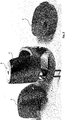
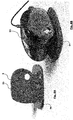
- Fig. 1 well represents the disc lock in its overall configuration, in which the containment body is generally indicated by C, the slit F for insertion of the brake disc and the locking pin P is in the closed position.
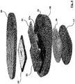
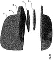
- the disc lock comprises a fork armour body 1, a key clamping block 2 secured to one of the arms of the fork 1, a locking pin P protruding from the clamping key block 2, an active core 3, and a closure and fitting cover 4.
- the armour body 1 has a main portion in the form of a fork, with two arms 11 and 12, and a connecting portion 13, defining therebetween the slit F for introducing a brake disc, and an accommodating compartment 14, perpendicularly protruding from the distal end of an arm 11. All these elements are integrally formed to constitute the armour body. Both arms 11 and 12 of the fork 1 have large apertures.
- the accommodating compartment 14 is hollow, so as to accommodate the lock clamping key block 2 and the respective locking pin P.
- the arm 12 opposite to the arm 11 from which the compartment 14 extends, has a housing chamber 15 adapted to host the active core 3 which will be described further below.
- the entire armour body 1 is of a material resistant to possible tampering attempts, for example of steel. Preferably, it is integrally obtained, so as not to present any connections that would make it more vulnerable.
- the two arms 11 and 12 have a width at least equal to that of the accommodating compartment 14 and are in the shape of plates with a large central aperture, respectively an upper aperture 11a and a lower aperture 12a.
- the aperture 11a on the arm 11 to which the lock key block 2 is integral with may be very wide, because it will in any case be partially protected at the bottom by the presence of the brake disc that would prevent reaching the housing chamber 15 on the opposed arm 12.
- the aperture 12a on the arm 12 of the disc lock accommodating the housing chamber 15 is of a size substantially corresponding to that of a transmission antenna of the active core 3, which will be described below.
- the upper aperture 11a is intended to be closed to view by the closure component 4, made of a material substantially transparent to electromagnetic waves, for example of plastic material.
- the purpose of the closure component 14 is not structural, but only to serve as a connection body part between the arm 11 of the fork 1 and the compartment 14.
- the lower aperture 12 is intended to be closed by a cover 16 of material transparent to electromagnetic waves, but of high tenacity and strength, for example of ceramic material or non-conductive composite material, for example kevlar.
- the closure cover 16 is preferably covered externally by a shock-proof flat shell 17, for instance made of shock-absorbing ABS, which can be coloured and finished in a similar and consistent manner with the material of the closure component 4.
- the active unit 3 is housed inside the housing chamber 15.
- the active unit 3 is constituted by a plastic material container 31, which is substantially transparent to electromagnetic waves, in which the components necessary for making an active anti-tampering device, for instance of the type described in WO2013/182971 , are incorporated.
- an electronic board 32, a battery 33, and a receiving winding 34 are incorporated into the container 31.
- the container 31 is closed by a shell 35.
- the entire container 31 with its closing shell 35 has a conformation and thickness suitable to find position in the housing chamber 15 of the arm 12 opposed to the arm 11 to which the lock key block 2 is integral.
- the electronic board 32 has a transmission antenna (with frequency determined by the intended functionality of the circuit) lying in a plan in a position corresponding to that of the cover 16 and the upper aperture 11a and lower aperture 12a.
- the container 31, the shell 17 for the protection of the cover 16 and the closing shell 35 are preferably made of the same plastic material, so that they can be welded together (for example, by ultrasounds) and constitute a single, sealed and sturdy casing.
- No inlet/outlet port of the electronic system is provided, because the transmission to the outside is through a transmission antenna (not shown) and the energy input to charge the battery 33 is provided via a wireless system, that is, through the receiving winding 34 (as will be described later).
- the container 31 - and possibly the shell 35 - is also crossed by a through hole 36 that is provided near the circuit board 32, in particular near its proximity sensor 32a.
- the hole 36 is intended to accommodate the end portion of the locking pin P on which a positioning element P 1 is obtained, suitable for being detected by the proximity sensor 32a: for example, the positioning element P 1 is in the form of a magnetic button inserted in a predetermined angular position of the locking pin P.
- the terminal end of the pin P also has an angular sector-shaped detent P 3 , which is configured to remain into an undercut external to the lower arm 12 in both angular locking positions.
- a hole 18 is provided in the bottom of the housing chamber 15 with a section corresponding to that of the detent P 3 , so that the detent P 3 can pass through during the extraction and retraction of the pin P, but then remain into an undercut in the two angular locking positions.
- a wireless system of known type per se is used, which transfers energy to the receiving winding 34 by means of proximity communication.
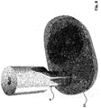
- the system of the invention provides a charging base 5 to be introduced into the slit F of the disc lock, provided with a transmission winding 51 suitable for transferring energy to the receiving winding 34 inside the active unit 3.
- the transmission winding 51 is embedded in the base 5 together with its electrical control unit 52 which in turn draws electrical power from an external port 53 exposed to the outside of the base 5, for example a micro-USB port.
- the base 5 has a shape and a thickness that are perfectly matched with the shape and width of the slit F of the disc lock. This makes the charging process particularly convenient because the disc lock is easily retained on the charging base without having to resort to other arrangements to keep the two charging windings in the correct proximity.
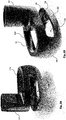
- the base 5 is also fixed perpendicular to a respective flat pedestal 54 which also acts as a support for the same disc lock when it is placed in the charging position, as well shown in Fig. 8B .
- the flat pedestal 54 is preferably provided with appropriate fixing members on the lower side, which allow it to be fastened to a plane but also to a frame (for example, the same frame of a motorcycle).
- the base 5 has a through hole in correspondence with the locking pin so that the disc lock can be firmly secured to the base: this allows to fasten the pedestal 54 in any configuration, avoiding the possibility that the disc lock may fall.
- the specific construction/configuration of the armour body allows the active unit to incorporate an electromagnetic wave transmission element that is not shielded by the sturdy material of the disc lock.
- the presence of the upper and lower apertures in the fork arms allows for a wide transmission range in the two opposite directions. Nevertheless, the robustness of the disc lock is not compromised, and the active electronic part is still sufficiently protected by any intrusion attempts with tools from the outside: in fact, the upper aperture does not leave access to the active unit, because there is the interposition of a brake disc, while the lower aperture is protected by the closing cover of ceramic or composite material.
- the locking pin which can be operated with the lock key block, acts both as a conventional mechanical locking mechanism and as a start-up switch of the active unit.
- the two locking positions of the pin P allow the user to choose whether or not to activate the electronic part of the anti-tampering system, but also allow the lock disc to be carried in the closed configuration (hence with the lock key block in the minimum footprint position) without activating the electronic anti-tampering system.
- the active core arrangement on the fork arm opposite the lock key block makes it easy to detect the lock condition of the locking pin as the end of the pin ends near the electronic board located in the housing chamber on the fork arm.
- the original wireless charging base configuration defines a system complete with a disc lock and its support, which is very user-friendly and easy-to-use.
- closure component 4 - substantially transparent to electromagnetic waves - has been briefly illustrated with a general function of aesthetic connection of external surfaces, may also have a more substantial function.
- it can act as a simple container or house a self-powered siren body or other device that is not critical to the operation of the disc lock.
Landscapes
- Engineering & Computer Science (AREA)
- Mechanical Engineering (AREA)
- Lock And Its Accessories (AREA)
Applications Claiming Priority (1)
| Application Number | Priority Date | Filing Date | Title |
|---|---|---|---|
| ITUA2016A003224A ITUA20163224A1 (it) | 2016-05-06 | 2016-05-06 | Bloccadisco allarmato |
Publications (1)
| Publication Number | Publication Date |
|---|---|
| EP3241726A1 true EP3241726A1 (en) | 2017-11-08 |
Family
ID=56940130
Family Applications (1)
| Application Number | Title | Priority Date | Filing Date |
|---|---|---|---|
| EP17169960.6A Withdrawn EP3241726A1 (en) | 2016-05-06 | 2017-05-08 | Alarmed disc lock |
Country Status (2)
| Country | Link |
|---|---|
| EP (1) | EP3241726A1 (it) |
| IT (1) | ITUA20163224A1 (it) |
Cited By (1)
| Publication number | Priority date | Publication date | Assignee | Title |
|---|---|---|---|---|
| GB2590939A (en) * | 2020-01-08 | 2021-07-14 | Milenco Ltd | A disk lock |
Citations (6)
| Publication number | Priority date | Publication date | Assignee | Title |
|---|---|---|---|---|
| FR2757474A1 (fr) * | 1996-12-20 | 1998-06-26 | Allouche Joelle Nicole Chantal | Dispositif antivol de haute securite pour engins motorises |
| DE102004054331A1 (de) * | 2003-11-10 | 2005-06-23 | Van Der Veer Designers B.V. | Fahrradschloss |
| CN201447975U (zh) * | 2009-03-11 | 2010-05-05 | 黄志伟 | 新型摩托车碟刹锁 |
| EP2189361A1 (en) * | 2008-11-20 | 2010-05-26 | Magneti Marelli S.p.A. | Anti-theft system for motor-vehicles, particularly for motorcycles |
| CN203078642U (zh) * | 2012-08-15 | 2013-07-24 | 黄志伟 | 摩托车碟刹锁 |
| CN203766949U (zh) * | 2013-10-30 | 2014-08-13 | 温州市瓯海吉洲锁厂 | 摩托车遥控碟刹锁 |
-
2016
- 2016-05-06 IT ITUA2016A003224A patent/ITUA20163224A1/it unknown
-
2017
- 2017-05-08 EP EP17169960.6A patent/EP3241726A1/en not_active Withdrawn
Patent Citations (6)
| Publication number | Priority date | Publication date | Assignee | Title |
|---|---|---|---|---|
| FR2757474A1 (fr) * | 1996-12-20 | 1998-06-26 | Allouche Joelle Nicole Chantal | Dispositif antivol de haute securite pour engins motorises |
| DE102004054331A1 (de) * | 2003-11-10 | 2005-06-23 | Van Der Veer Designers B.V. | Fahrradschloss |
| EP2189361A1 (en) * | 2008-11-20 | 2010-05-26 | Magneti Marelli S.p.A. | Anti-theft system for motor-vehicles, particularly for motorcycles |
| CN201447975U (zh) * | 2009-03-11 | 2010-05-05 | 黄志伟 | 新型摩托车碟刹锁 |
| CN203078642U (zh) * | 2012-08-15 | 2013-07-24 | 黄志伟 | 摩托车碟刹锁 |
| CN203766949U (zh) * | 2013-10-30 | 2014-08-13 | 温州市瓯海吉洲锁厂 | 摩托车遥控碟刹锁 |
Non-Patent Citations (1)
| Title |
|---|
| CHRISTOPHER MCGRAW: "SPECS / REVIEWS FOR SALE Crowdfunding Combat: BitLock vs. Lock8 Smart Bike Locks", AUTOBLOG.COM, 29 October 2013 (2013-10-29), www.autoblog.com, pages 1 - 9, XP055281138, Retrieved from the Internet <URL:http://www.autoblog.com/2013/10/29/crowdfunding-combat-bitlock-vs-lock8-smart-bike-locks/> [retrieved on 20160616] * |
Cited By (1)
| Publication number | Priority date | Publication date | Assignee | Title |
|---|---|---|---|---|
| GB2590939A (en) * | 2020-01-08 | 2021-07-14 | Milenco Ltd | A disk lock |
Also Published As
| Publication number | Publication date |
|---|---|
| ITUA20163224A1 (it) | 2017-11-06 |
Similar Documents
| Publication | Publication Date | Title |
|---|---|---|
| CA2879857C (en) | Integrated antenna coil in a metallic body | |
| CN203201321U (zh) | 与商品一起使用的安全装置 | |
| CN103149830B (zh) | 具有车辆智能钥匙功能的手表 | |
| CN103986035B (zh) | 通信连接器 | |
| US7921682B1 (en) | Padlock with alarm function | |
| FI83805C (fi) | Saekerhetsbehaollare. | |
| JP6361832B2 (ja) | 無線通信デバイス付き鍵及び無線通信デバイス付き鍵用錠 | |
| CN106481188A (zh) | 带有按压式指纹传感器的保险箱 | |
| CN216741096U (zh) | 一种智能挂锁 | |
| US12451919B2 (en) | Modular customizable ruggedized protective case with detachable sidewall for mobile device | |
| GB2508896A (en) | A portable lock | |
| US10133887B1 (en) | Card reader and electronic protection module thereof | |
| CN201891303U (zh) | 具有报警功能的锁具 | |
| KR20180046660A (ko) | Rfid태그를 갖는 휴대단말기용 액세서리 | |
| US20150076231A1 (en) | Ultra Thin Proximity Card Reader | |
| CN105455347A (zh) | 一种智能钱包 | |
| CN210988634U (zh) | 一种智能安全递送手提箱 | |
| KR200477958Y1 (ko) | 외부에 현금보관부가 형성된 스마트폰 다이어리케이스 | |
| CN222194361U (zh) | 卡套结构 | |
| CN215803774U (zh) | 一种智能门锁的防钻结构及智能门锁 | |
| CN212802892U (zh) | 感应锁 | |
| CN112956800A (zh) | 一种箱包安全防盗保护系统 | |
| CN206753282U (zh) | 用于车锁的壳体、车锁以及车辆 | |
| CN111445653A (zh) | 声磁防盗件及其偏置件 | |
| CN215632309U (zh) | 一种锁具和款包 |
Legal Events
| Date | Code | Title | Description |
|---|---|---|---|
| PUAI | Public reference made under article 153(3) epc to a published international application that has entered the european phase |
Free format text: ORIGINAL CODE: 0009012 |
|
| AK | Designated contracting states |
Kind code of ref document: A1 Designated state(s): AL AT BE BG CH CY CZ DE DK EE ES FI FR GB GR HR HU IE IS IT LI LT LU LV MC MK MT NL NO PL PT RO RS SE SI SK SM TR |
|
| AX | Request for extension of the european patent |
Extension state: BA ME |
|
| 17P | Request for examination filed |
Effective date: 20180720 |
|
| RBV | Designated contracting states (corrected) |
Designated state(s): AL AT BE BG CH CY CZ DE DK EE ES FI FR GB GR HR HU IE IS IT LI LT LU LV MC MK MT NL NO PL PT RO RS SE SI SK SM TR |
|
| GRAP | Despatch of communication of intention to grant a patent |
Free format text: ORIGINAL CODE: EPIDOSNIGR1 |
|
| RIC1 | Information provided on ipc code assigned before grant |
Ipc: B62H 5/14 20060101AFI20180911BHEP Ipc: B62H 5/18 20060101ALI20180911BHEP |
|
| INTG | Intention to grant announced |
Effective date: 20180928 |
|
| GRAJ | Information related to disapproval of communication of intention to grant by the applicant or resumption of examination proceedings by the epo deleted |
Free format text: ORIGINAL CODE: EPIDOSDIGR1 |
|
| GRAP | Despatch of communication of intention to grant a patent |
Free format text: ORIGINAL CODE: EPIDOSNIGR1 |
|
| INTG | Intention to grant announced |
Effective date: 20181119 |
|
| STAA | Information on the status of an ep patent application or granted ep patent |
Free format text: STATUS: THE APPLICATION IS DEEMED TO BE WITHDRAWN |
|
| 18D | Application deemed to be withdrawn |
Effective date: 20190330 |