EP3241752A1 - Systeme und verfahren zum zurückhalten einer abnehmbaren platte bei der installation eines evakuierungssystems - Google Patents
Systeme und verfahren zum zurückhalten einer abnehmbaren platte bei der installation eines evakuierungssystems Download PDFInfo
- Publication number
- EP3241752A1 EP3241752A1 EP17166197.8A EP17166197A EP3241752A1 EP 3241752 A1 EP3241752 A1 EP 3241752A1 EP 17166197 A EP17166197 A EP 17166197A EP 3241752 A1 EP3241752 A1 EP 3241752A1
- Authority
- EP
- European Patent Office
- Prior art keywords
- strap
- blow
- out panel
- inflatable
- coupled
- Prior art date
- Legal status (The legal status is an assumption and is not a legal conclusion. Google has not performed a legal analysis and makes no representation as to the accuracy of the status listed.)
- Granted
Links
Images


Classifications
-
- B—PERFORMING OPERATIONS; TRANSPORTING
- B64—AIRCRAFT; AVIATION; COSMONAUTICS
- B64D—EQUIPMENT FOR FITTING IN OR TO AIRCRAFT; FLIGHT SUITS; PARACHUTES; ARRANGEMENT OR MOUNTING OF POWER PLANTS OR PROPULSION TRANSMISSIONS IN AIRCRAFT
- B64D25/00—Emergency apparatus or devices, not otherwise provided for
- B64D25/08—Ejecting or escaping means
- B64D25/14—Inflatable escape chutes
Definitions
- the present disclosure relates to aircraft evacuation systems and, in particular, to retaining systems for evacuation system blow-out panels.
- Emergency evacuation systems may be used to exit an aircraft absent a jet way or other suitable means of egress for passengers.
- the evacuation system may deploy from the side of an aircraft fuselage, for example.
- a blow-out panel covers a compartment where the evacuation system is stored.
- a portion of the evacuation system i.e., a slide or a raft
- An evacuation system for an aircraft may comprise a packboard, an inflatable configured to be packed into the packboard, a blow-out panel for the packboard, the blow-out panel having an outboard surface comprising an air-flow surface and having an inner surface, a first strap coupled to the inner surface of the blow-out panel and to the packboard and a second strap coupled to the inner surface of the blow-out panel and to the inflatable.
- the first strap may be coupled to the blow-out panel in close proximity to a first edge of the blow-out panel and the second strap may be coupled to the blow-out panel in close proximity to a second edge of the blow-out panel, the first edge being positioned opposite the second edge of the blow-out panel.
- the invention provides an evacuation system as claimed in claim 1.
- a third strap may be coupled between the blow-out panel and the packboard.
- the first strap may be located in close proximity to a first corner of the blow-out panel and the third strap may be located in close proximity to a second corner of the blow-out panel.
- the second strap may be located between 25% and 75% of a distance between a third corner of the blow-out panel and a fourth corner of the blow-out panel.
- a third strap may be coupled between the blow-out panel and the inflatable.
- the second strap may be located in close proximity to third corner of the blow-out panel and the third strap may be located in close proximity to a fourth corner of the blow-out panel.
- the first strap may be located between 25% and 75% of a distance between a first corner of the blow-out panel and a second corner of the blow-out panel of the blow-out panel.
- a fourth strap may be coupled between the blow-out panel and the packboard. The first strap may be located in close proximity to a first corner of the blow-out panel and the fourth strap may be located in close proximity to a second corner of the blow-out panel.
- the second strap may be coupled to an outboard portion of the inflatable in response to the inflatable being in a fully deployed position.
- a method for retaining a blow-out panel to an evacuation system may comprise attaching a first end of a first strap to an inner surface of the blow-out panel, attaching a second end of the first strap to a packboard, attaching a first end of a second strap to the inner surface of the blow-out panel, and attaching a second end of the second strap to an inflatable.
- the method may further comprise providing at least one of the first strap, the second strap, the blow-out panel, the packboard, or the inflatable.
- the attaching the second end of the second strap to the inflatable may comprise attaching the second end to an outboard portion of the inflatable.
- the attaching may include at least one of sewing, adhering, coupling via a fastener, or coupling via a shackle.
- the method may further comprise attaching a first end of a third strap to the blow-out panel, and attaching a second end of the third strap to the packboard.
- an evacuation system for an aircraft may comprise an inflatable, a packboard for the inflatable, a plurality of straps, a blow-out panel coupled between the inflatable and the packboard via the plurality of straps, the plurality of straps including at least a first strap and a second strap, wherein the at least one first strap is coupled between an inner surface of the blow-out panel and the packboard and the at least one second strap is coupled between the inner surface of the blow-out panel and the inflatable, and wherein the blow-out panel is configured to be suspended between an outboard portion of the inflatable and the packboard in response to the inflatable deploying to a fully deployed position.
- the packboard may be located above a wing of the aircraft.
- the plurality of straps may comprise at least one of wire, cable, webbing rope, string, or tape.
- the second strap may be coupled between the inner surface of the blow-out panel and an outboard portion of the inflatable in response to the inflatable deploying to a fully deployed position.
- the first strap and the second strap may be pulled taught in response to the inflatable deploying to the fully deployed position.
- any reference to singular includes plural embodiments, and any reference to more than one component or step may include a singular embodiment or step.
- any reference to attached, fixed, connected or the like may include permanent, removable, temporary, partial, full and/or any other possible attachment option.
- any reference to without contact (or similar phrases) may also include reduced contact or minimal contact.
- Surface cross hatching lines may be used throughout the figures to denote different parts but not necessarily to denote the same or different materials.
- Evacuation systems of the present disclosure include a blow-out panel removably coupled to a packboard, wherein an inflatable is stored.
- the blow-out panel may decouple from the packboard in response to the inflatable being deployed.
- a plurality of straps may be coupled to the blow-out panel in order to retain the blow-out panel to the evacuation system.
- the blow-out panel in response to the inflatable being deployed, the blow-out panel may be coupled between the inflatable and the packboard via the plurality of straps.
- Evacuation system 100 may include packboard 112 and blow-out panel (BOP) 110.
- an aircraft may comprise a fuselage 102 and a wing 104. Wing 104 may be mechanically coupled to fuselage 102 at a fairing 106.
- Packboard 112 may be located in fairing 106.
- Packboard 112 and BOP 110 may be located above wing 104.
- packboard 112 may be located in fuselage 102. In this manner, packboard may be coupled to at least one of fairing 106 or fuselage 102.
- BOP 110 may be coupled to packboard 112, in accordance with various embodiments.
- BOP 110 is removably coupled to packboard 112.
- BOP 110 may comprise an outboard surface 120.
- Outboard surface 120 of BOP 110 may comprise an air-flow surface.
- FIG. 1 provides an exemplary aircraft configuration and that it is contemplated herein that evacuation system 100 may be used with any suitable wing/fuselage configuration.
- BOP 110 may be coupled to packboard 112 via one or more straps, such as strap 212.
- strap 212 may comprise at least one of wire, cable, webbing (e.g., nylon or polyester webbing) rope, string, and tape.
- a strap may be directly coupled to the BOP 110, wherein the term "directly" in this regard means that there are no other members between the strap and the BOP other than perhaps an attachment feature, fastener, or other means for coupling a strap to a BOP.
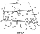
- BOP 110 may comprise a number of corners including first corner 240, second corner 242, third corner 244, and fourth corner 246.
- BOP 110 may include inner surface 222.
- Inner surface 222 may face inboard (i.e., the negative y-direction in FIG. 1 ) when in an installed position, as illustrated in FIG. 1 .
- BOP 110 may comprise a quadrilateral-type shape.
- BOP 110 may be coupled to three straps including first strap 212, second strap 214, and third strap 216.
- First strap 212 may be coupled directly to BOP 110.
- First strap 212 may be coupled to BOP 110 in close proximity to first edge 232, wherein the term "close proximity” in this regard means that the first strap 212 is closer to the first edge 232 than the second edge 234, in accordance with various embodiments.
- First strap 212 may be coupled to BOP 110 in close proximity to first corner 240, wherein the term "close proximity” in this regard means that first strap 212 is coupled closer to first corner 240 than to second corner 242, in accordance with various embodiments.
- first strap 212 may be coupled to packboard 112 (see FIG. 1 and FIG. 4 ).
- second strap 214 may be coupled directly to BOP 110.
- Second strap 214 may be coupled to BOP 110 in close proximity to second edge 232, wherein the term "close proximity" in this regard means that second strap 214 is closer to second edge 234 than first edge 232, in accordance with various embodiments.
- Second strap 214 may be coupled to BOP 110 at a point located between third corner 244 and a fourth corner 246.
- Second strap 214 may be coupled to BOP 110 at a location between 25% and 75% of a distance 250 between third corner 244 and fourth corner 246.
- Second strap 214 may be coupled to BOP 110 at a location midway or substantially midway between third corner 244 and a fourth corner 246.
- Second strap 214 may be coupled to inflatable 460 (see FIG.
- third strap 216 may be coupled directly to BOP 110.
- Third strap 216 may be coupled to BOP 110 in close proximity to first edge 232, wherein the term "close proximity” in this regard means that the third strap 216 is closer to the first edge 232 than the second edge 234, in accordance with various embodiments.
- Third strap 216 may be coupled to BOP 110 in close proximity to second corner 242, wherein the term "close proximity” in this regard means that third strap 216 is coupled closer to second corner 242 than to first corner 240, in accordance with various embodiments.
- Third strap 216 may be coupled to packboard 112 (see FIG. 1 and FIG. 4 ). The strap attachment locations may cause the BOP 110 to pivot away from an aircraft fuselage in a controlled manner in response to an inflatable being deployed.
- a strap such as third strap 216 for example, may be coupled to inner surface 222 of BOP 110 via a shackle 320 and a loop 322.
- Strap 216 may comprise a loop (also referred to herein as a first loop) 317.
- a loop (also referred to herein as a second loop) 322 may be attached to inner surface 222.
- Loop 322 may be adhered onto inner surface 222.
- loop 322 may be sewn onto a material 324 wherein the material is 324 adhered to inner surface 222.
- Shackle 320 may extend through loop 317 and through loop 322, thus coupling strap 216 to inner surface 222.
- strap 216 may be attached to inner surface 222 via any suitable fastener, means, or method.
- a sleeve 318 may be configured to slide over shackle 320.
- Sleeve 318 may be coupled to strap 216.
- Sleeve 318 may slide relative to strap 216 to cover shackle 320.
- Sleeve 318 may protect adjacent components, such as an inflatable, from shackle 320.
- FIG. 4 elements with like element numbering, as depicted in FIG. 1 , are intended to be the same and will not necessarily be repeated for the sake of clarity.
- an inflatable 460 being deployed from a packboard 112 is illustrated, in accordance with various embodiments.
- inflatable 460 may be positioned or "packed" into packboard 112.
- BOP 110 may be decoupled from packboard 112.
- inflatable 460 may begin to inflate with air.
- inflatable 460 may exit packboard 112.
- BOP 110 may be suspended between inflatable 460 and packboard 112.
- First strap 212, second strap 214, and third strap 216 may retain BOP 110 to evacuation system 100.
- inflatable 460 is illustrated in a fully deployed position, in accordance with various embodiments.
- BOP 110 may be located beneath inflatable 460 in response to inflatable 460 moving to a deployed position, as shown in FIG. 5 .
- BOP 110 may be located between inflatable 460 and wing 104 in response to inflatable 460 moving to a deployed position, as shown in FIG. 5 .
- BOP 110 may be coupled between inflatable 460 and packboard 112 (see FIG. 4 ) in response to inflatable 460 moving to a deployed position, as shown in FIG. 5 .
- Second strap 214 may be coupled to outboard portion 462 of inflatable 460 in response to inflatable 460 moving to a deployed position, as shown in FIG. 5 .
- Second strap 214 may be taut in response to inflatable 460 moving to a deployed position, as shown in FIG. 5 . Configuring second strap 214 to be taut in response to inflatable 460 moving to a deployed position may prevent BOP 110 from "flapping" and causing damage to itself or to adjacent components, such as wing 104 and inflatable 460. Inner surface (see FIG. 2A ) of BOP 110 may face inflatable 460 in response to inflatable 460 being in a deployed position.
- first strap 212 may be coupled to BOP 110 at a location between 25% and 75% of a distance 252 between first corner 240 and second corner 242.
- First strap 212 may be coupled to BOP 110 at a location midway, or substantially midway, between first corner 240 and second corner 242.
- second strap 214 may be coupled to BOP 110 in close proximity to third corner 244, wherein the term "close proximity" in this regard means that second strap 214 is coupled closer to third corner 244 than to fourth corner 246.
- third strap 216 may be coupled to BOP 110 in close proximity to second edge 234, wherein the term "close proximity” in this regard means that third strap 216 is closer to second edge 234 than first edge 232.
- Third strap 216 may be coupled to BOP 110 in close proximity to fourth corner 246, wherein the term “close proximity” in this regard means that third strap 216 is coupled closer to fourth corner 246 than to third corner 244, in accordance with various embodiments.
- Third strap 216 may be coupled to inflatable 460 (see FIG. 4 ).
- fourth strap 218 may be coupled directly to BOP 110.
- Fourth strap 218 may be coupled to BOP 110 in close proximity to first edge 232, wherein the term "close proximity” in this regard means that fourth strap 218 is closer to first edge 232 than second edge 234, in accordance with various embodiments.
- Fourth strap 218 may be coupled to BOP 110 in close proximity to second corner 242, wherein the term "close proximity” in this regard means that fourth strap 218 is coupled closer to second corner 242 than to first corner 240, in accordance with various embodiments.
- Fourth strap 218 may be coupled to packboard 112 (see FIG. 1 and FIG. 4 ).
- fourth strap 218 may be coupled between packboard 112 and BOP 110.
- a third strap may add stability to BOP 110 when BOP 110 is suspended between inflatable 460 and packboard 112.
- a third strap may prevent BOP 110 from rotating.
- a fourth strap may provide further stability in this regard.
- first straps i.e., first strap 212 coupled to first edge 232 of BOP 110 may vary in length with respect to straps (i.e., second strap 214) coupled to second edge 234 of BOP 110.
- first strap 212 and/or second strap 214 may comprise a length such that first strap 212 and/or second strap 214 may be able to fold up with inflatable 460 in order to stow inflatable 460 into packboard 112.
- first strap 212 may be shorter than second strap 214. This may allow BOP to remain closer to packboard 112.
- method 600 may include attaching a first end of a first strap to a blow-out panel, in step 610.
- Method 600 may include attaching a second end of the first strap to a packboard, in step 620.
- Method 600 may include attaching a first end of a second strap to the blow-out panel, in step 630.
- Method 600 may include attaching a second end of the second strap to an inflatable, in step 640.
- step 610 may include attaching first end 282 of first strap 212 to blow-out panel (BOP) 110.
- Step 620 may include attaching second end 281 of first strap 212 to packboard 112.
- Step 630 may include attaching first end 283 of second strap 214 to BOP 110.
- Step 640 may include attaching second end 284 of second strap 214 to inflatable 460.
- references to "various embodiments”, “one embodiment”, “an embodiment”, “an example embodiment”, etc. indicate that the embodiment described may include a particular feature, structure, or characteristic, but every embodiment may not necessarily include the particular feature, structure, or characteristic. Moreover, such phrases are not necessarily referring to the same embodiment. Further, when a particular feature, structure, or characteristic is described in connection with an embodiment, it is submitted that it is within the knowledge of one skilled in the art to affect such feature, structure, or characteristic in connection with other embodiments whether or not explicitly described. After reading the description, it will be apparent to one skilled in the relevant art(s) how to implement the disclosure in alternative embodiments.
Landscapes
- Business, Economics & Management (AREA)
- Emergency Management (AREA)
- Engineering & Computer Science (AREA)
- Aviation & Aerospace Engineering (AREA)
- Air Bags (AREA)
- Tents Or Canopies (AREA)
- Emergency Lowering Means (AREA)
- Aiming, Guidance, Guns With A Light Source, Armor, Camouflage, And Targets (AREA)
Applications Claiming Priority (1)
| Application Number | Priority Date | Filing Date | Title |
|---|---|---|---|
| US15/148,632 US10494109B2 (en) | 2016-05-06 | 2016-05-06 | Systems and methods for retaining removable panel when deploying evacuation system |
Publications (2)
| Publication Number | Publication Date |
|---|---|
| EP3241752A1 true EP3241752A1 (de) | 2017-11-08 |
| EP3241752B1 EP3241752B1 (de) | 2020-04-22 |
Family
ID=58547351
Family Applications (1)
| Application Number | Title | Priority Date | Filing Date |
|---|---|---|---|
| EP17166197.8A Active EP3241752B1 (de) | 2016-05-06 | 2017-04-12 | Systeme und verfahren zum zurückhalten einer abnehmbaren platte bei der installation eines evakuierungssystems |
Country Status (5)
| Country | Link |
|---|---|
| US (1) | US10494109B2 (de) |
| EP (1) | EP3241752B1 (de) |
| CN (1) | CN107344624B (de) |
| BR (1) | BR102017005226B1 (de) |
| CA (1) | CA2958654C (de) |
Cited By (1)
| Publication number | Priority date | Publication date | Assignee | Title |
|---|---|---|---|---|
| EP3757011A1 (de) * | 2019-06-26 | 2020-12-30 | Goodrich Corporation | Verfahren und system zum halten einer auswerfbaren klappe einer flügelnotrutsche |
Families Citing this family (6)
| Publication number | Priority date | Publication date | Assignee | Title |
|---|---|---|---|---|
| EP3501974B1 (de) * | 2017-12-19 | 2020-02-05 | LEONARDO S.p.A. | Hubschrauber mit einem notausgang |
| US10787269B2 (en) * | 2018-01-04 | 2020-09-29 | Goodrich Corporation | Automatic retracting firing cable |
| US11447257B2 (en) * | 2018-07-06 | 2022-09-20 | Goodrich Corporation | Systems and methods for soft cover attachment |
| US11148760B2 (en) | 2019-07-02 | 2021-10-19 | Goodrich Corporation | Flotation device with boarding apparatus |
| EP3854679B1 (de) * | 2020-01-24 | 2023-10-25 | Airbus Helicopters | Fahrzeug mit mindestens einem notausstiegssystem |
| US20210354836A1 (en) * | 2020-05-12 | 2021-11-18 | Goodrich Corporation | Symmetrical dual action restraint |
Citations (3)
| Publication number | Priority date | Publication date | Assignee | Title |
|---|---|---|---|---|
| EP1254834A1 (de) * | 2001-05-02 | 2002-11-06 | Airbus France | Schnelle Evakuationseinheit für ein Luftfahrzeug |
| EP1759993A2 (de) * | 2005-08-31 | 2007-03-07 | Goodrich Corporation | Notrutsche mit Hauptüberdruckventil |
| EP1911674A2 (de) * | 2006-10-12 | 2008-04-16 | Goodrich Corporation | Rumpfmontiertes Abführungsgleitsystem |
Family Cites Families (7)
| Publication number | Priority date | Publication date | Assignee | Title |
|---|---|---|---|---|
| US3771749A (en) * | 1973-01-05 | 1973-11-13 | Garrett Corp | Emergency aircraft evacuation apparatus and method |
| EP0039466A1 (de) | 1980-05-01 | 1981-11-11 | The B.F. GOODRICH Company | Notrutsche mit vielfachen Aufblasvorrichtungen |
| US5102070A (en) * | 1991-06-13 | 1992-04-07 | Air Cruisers Company | Inflatable aircraft evacuation slide arrangement |
| DE102010055704A1 (de) * | 2010-12-22 | 2012-06-28 | Airbus Operations Gmbh | System zur Evakuierung von Personen aus einem Fahrzeug |
| FR2999526A1 (fr) * | 2012-12-13 | 2014-06-20 | Airbus Operations Sas | Cockpit d'aeronef a issue de secours par une glace centrale |
| US9457911B2 (en) | 2013-02-11 | 2016-10-04 | Air Cruisers Company | Emergency evacuation systems door restraint lanyard for aircraft |
| CA2915256C (en) * | 2013-06-17 | 2021-03-16 | Zodiac Aerosafety Systems | Self-tensioning girt |
-
2016
- 2016-05-06 US US15/148,632 patent/US10494109B2/en active Active
-
2017
- 2017-02-21 CA CA2958654A patent/CA2958654C/en active Active
- 2017-03-15 BR BR102017005226-5A patent/BR102017005226B1/pt active IP Right Grant
- 2017-04-12 EP EP17166197.8A patent/EP3241752B1/de active Active
- 2017-05-05 CN CN201710323905.6A patent/CN107344624B/zh active Active
Patent Citations (3)
| Publication number | Priority date | Publication date | Assignee | Title |
|---|---|---|---|---|
| EP1254834A1 (de) * | 2001-05-02 | 2002-11-06 | Airbus France | Schnelle Evakuationseinheit für ein Luftfahrzeug |
| EP1759993A2 (de) * | 2005-08-31 | 2007-03-07 | Goodrich Corporation | Notrutsche mit Hauptüberdruckventil |
| EP1911674A2 (de) * | 2006-10-12 | 2008-04-16 | Goodrich Corporation | Rumpfmontiertes Abführungsgleitsystem |
Cited By (2)
| Publication number | Priority date | Publication date | Assignee | Title |
|---|---|---|---|---|
| EP3757011A1 (de) * | 2019-06-26 | 2020-12-30 | Goodrich Corporation | Verfahren und system zum halten einer auswerfbaren klappe einer flügelnotrutsche |
| US11117673B2 (en) | 2019-06-26 | 2021-09-14 | Goodrich Corporation | Method and system for retaining off-wing evacuation slide blowout panel |
Also Published As
| Publication number | Publication date |
|---|---|
| CN107344624A (zh) | 2017-11-14 |
| CA2958654A1 (en) | 2017-11-06 |
| EP3241752B1 (de) | 2020-04-22 |
| CA2958654C (en) | 2023-10-03 |
| US10494109B2 (en) | 2019-12-03 |
| US20170320583A1 (en) | 2017-11-09 |
| CN107344624B (zh) | 2021-10-08 |
| BR102017005226A2 (pt) | 2017-11-21 |
| BR102017005226B1 (pt) | 2024-04-30 |
Similar Documents
| Publication | Publication Date | Title |
|---|---|---|
| CA2958654C (en) | Systems and methods for retaining removable panel when deploying evacuation system | |
| US10752368B2 (en) | Asymmetric yoke | |
| US11027851B2 (en) | Head restraint for parachute assemblies | |
| US10703495B2 (en) | Secondary release arrangement for evacuation slide systems | |
| US10131440B2 (en) | Inflatable evacuation system with canopy support | |
| EP3401221B1 (de) | Evakuierungsrutsche mit anti-kiting mitteln | |
| US20220388671A1 (en) | Systems and methods for soft cover attachment | |
| US11066176B2 (en) | Canopy support lane divider | |
| US10000292B1 (en) | Multipurpose lane divider for evacuation slide | |
| US10625870B1 (en) | Secured lines for ballistic recovery system | |
| EP3348485B1 (de) | Fortlaufende haltevorrichtung für notrutschensystem | |
| EP3378776A1 (de) | Windvorhang mit doppelkonfiguration für evakuierungsanordnung | |
| US11345478B2 (en) | Evacuation slide and method of forming evacuation slide having integral cable channel | |
| US10112684B1 (en) | Self supporting canopy | |
| US10654574B2 (en) | Airfoil for steadying an evacuation slide | |
| US11130586B2 (en) | Lane dividing apparatus | |
| US10351250B2 (en) | Releasable bulkhead | |
| US20070114332A1 (en) | Softer-parachute deployment deceleration assist device | |
| EP3816051A1 (de) | Integrierte traversenrückhaltung | |
| JP2023064065A (ja) | パラシュートアセンブリ用のサスペンションラインアセンブリ、パラシュートアセンブリ、及びパラシュートアセンブリの作成方法 |
Legal Events
| Date | Code | Title | Description |
|---|---|---|---|
| PUAI | Public reference made under article 153(3) epc to a published international application that has entered the european phase |
Free format text: ORIGINAL CODE: 0009012 |
|
| STAA | Information on the status of an ep patent application or granted ep patent |
Free format text: STATUS: THE APPLICATION HAS BEEN PUBLISHED |
|
| AK | Designated contracting states |
Kind code of ref document: A1 Designated state(s): AL AT BE BG CH CY CZ DE DK EE ES FI FR GB GR HR HU IE IS IT LI LT LU LV MC MK MT NL NO PL PT RO RS SE SI SK SM TR |
|
| AX | Request for extension of the european patent |
Extension state: BA ME |
|
| STAA | Information on the status of an ep patent application or granted ep patent |
Free format text: STATUS: REQUEST FOR EXAMINATION WAS MADE |
|
| 17P | Request for examination filed |
Effective date: 20180508 |
|
| RBV | Designated contracting states (corrected) |
Designated state(s): AL AT BE BG CH CY CZ DE DK EE ES FI FR GB GR HR HU IE IS IT LI LT LU LV MC MK MT NL NO PL PT RO RS SE SI SK SM TR |
|
| RIC1 | Information provided on ipc code assigned before grant |
Ipc: B64D 25/14 20060101AFI20191009BHEP |
|
| GRAP | Despatch of communication of intention to grant a patent |
Free format text: ORIGINAL CODE: EPIDOSNIGR1 |
|
| STAA | Information on the status of an ep patent application or granted ep patent |
Free format text: STATUS: GRANT OF PATENT IS INTENDED |
|
| INTG | Intention to grant announced |
Effective date: 20191121 |
|
| GRAS | Grant fee paid |
Free format text: ORIGINAL CODE: EPIDOSNIGR3 |
|
| GRAA | (expected) grant |
Free format text: ORIGINAL CODE: 0009210 |
|
| STAA | Information on the status of an ep patent application or granted ep patent |
Free format text: STATUS: THE PATENT HAS BEEN GRANTED |
|
| AK | Designated contracting states |
Kind code of ref document: B1 Designated state(s): AL AT BE BG CH CY CZ DE DK EE ES FI FR GB GR HR HU IE IS IT LI LT LU LV MC MK MT NL NO PL PT RO RS SE SI SK SM TR |
|
| REG | Reference to a national code |
Ref country code: CH Ref legal event code: EP |
|
| REG | Reference to a national code |
Ref country code: DE Ref legal event code: R096 Ref document number: 602017015029 Country of ref document: DE |
|
| REG | Reference to a national code |
Ref country code: IE Ref legal event code: FG4D |
|
| REG | Reference to a national code |
Ref country code: AT Ref legal event code: REF Ref document number: 1259760 Country of ref document: AT Kind code of ref document: T Effective date: 20200515 |
|
| REG | Reference to a national code |
Ref country code: LT Ref legal event code: MG4D |
|
| REG | Reference to a national code |
Ref country code: NL Ref legal event code: MP Effective date: 20200422 |
|
| PG25 | Lapsed in a contracting state [announced via postgrant information from national office to epo] |
Ref country code: GR Free format text: LAPSE BECAUSE OF FAILURE TO SUBMIT A TRANSLATION OF THE DESCRIPTION OR TO PAY THE FEE WITHIN THE PRESCRIBED TIME-LIMIT Effective date: 20200723 Ref country code: FI Free format text: LAPSE BECAUSE OF FAILURE TO SUBMIT A TRANSLATION OF THE DESCRIPTION OR TO PAY THE FEE WITHIN THE PRESCRIBED TIME-LIMIT Effective date: 20200422 Ref country code: PT Free format text: LAPSE BECAUSE OF FAILURE TO SUBMIT A TRANSLATION OF THE DESCRIPTION OR TO PAY THE FEE WITHIN THE PRESCRIBED TIME-LIMIT Effective date: 20200824 Ref country code: NO Free format text: LAPSE BECAUSE OF FAILURE TO SUBMIT A TRANSLATION OF THE DESCRIPTION OR TO PAY THE FEE WITHIN THE PRESCRIBED TIME-LIMIT Effective date: 20200722 Ref country code: NL Free format text: LAPSE BECAUSE OF FAILURE TO SUBMIT A TRANSLATION OF THE DESCRIPTION OR TO PAY THE FEE WITHIN THE PRESCRIBED TIME-LIMIT Effective date: 20200422 Ref country code: LT Free format text: LAPSE BECAUSE OF FAILURE TO SUBMIT A TRANSLATION OF THE DESCRIPTION OR TO PAY THE FEE WITHIN THE PRESCRIBED TIME-LIMIT Effective date: 20200422 Ref country code: SE Free format text: LAPSE BECAUSE OF FAILURE TO SUBMIT A TRANSLATION OF THE DESCRIPTION OR TO PAY THE FEE WITHIN THE PRESCRIBED TIME-LIMIT Effective date: 20200422 Ref country code: IS Free format text: LAPSE BECAUSE OF FAILURE TO SUBMIT A TRANSLATION OF THE DESCRIPTION OR TO PAY THE FEE WITHIN THE PRESCRIBED TIME-LIMIT Effective date: 20200822 |
|
| REG | Reference to a national code |
Ref country code: AT Ref legal event code: MK05 Ref document number: 1259760 Country of ref document: AT Kind code of ref document: T Effective date: 20200422 |
|
| PG25 | Lapsed in a contracting state [announced via postgrant information from national office to epo] |
Ref country code: HR Free format text: LAPSE BECAUSE OF FAILURE TO SUBMIT A TRANSLATION OF THE DESCRIPTION OR TO PAY THE FEE WITHIN THE PRESCRIBED TIME-LIMIT Effective date: 20200422 Ref country code: LV Free format text: LAPSE BECAUSE OF FAILURE TO SUBMIT A TRANSLATION OF THE DESCRIPTION OR TO PAY THE FEE WITHIN THE PRESCRIBED TIME-LIMIT Effective date: 20200422 Ref country code: RS Free format text: LAPSE BECAUSE OF FAILURE TO SUBMIT A TRANSLATION OF THE DESCRIPTION OR TO PAY THE FEE WITHIN THE PRESCRIBED TIME-LIMIT Effective date: 20200422 Ref country code: BG Free format text: LAPSE BECAUSE OF FAILURE TO SUBMIT A TRANSLATION OF THE DESCRIPTION OR TO PAY THE FEE WITHIN THE PRESCRIBED TIME-LIMIT Effective date: 20200722 |
|
| PG25 | Lapsed in a contracting state [announced via postgrant information from national office to epo] |
Ref country code: AL Free format text: LAPSE BECAUSE OF FAILURE TO SUBMIT A TRANSLATION OF THE DESCRIPTION OR TO PAY THE FEE WITHIN THE PRESCRIBED TIME-LIMIT Effective date: 20200422 |
|
| REG | Reference to a national code |
Ref country code: DE Ref legal event code: R097 Ref document number: 602017015029 Country of ref document: DE |
|
| PG25 | Lapsed in a contracting state [announced via postgrant information from national office to epo] |
Ref country code: ES Free format text: LAPSE BECAUSE OF FAILURE TO SUBMIT A TRANSLATION OF THE DESCRIPTION OR TO PAY THE FEE WITHIN THE PRESCRIBED TIME-LIMIT Effective date: 20200422 Ref country code: CZ Free format text: LAPSE BECAUSE OF FAILURE TO SUBMIT A TRANSLATION OF THE DESCRIPTION OR TO PAY THE FEE WITHIN THE PRESCRIBED TIME-LIMIT Effective date: 20200422 Ref country code: RO Free format text: LAPSE BECAUSE OF FAILURE TO SUBMIT A TRANSLATION OF THE DESCRIPTION OR TO PAY THE FEE WITHIN THE PRESCRIBED TIME-LIMIT Effective date: 20200422 Ref country code: AT Free format text: LAPSE BECAUSE OF FAILURE TO SUBMIT A TRANSLATION OF THE DESCRIPTION OR TO PAY THE FEE WITHIN THE PRESCRIBED TIME-LIMIT Effective date: 20200422 Ref country code: DK Free format text: LAPSE BECAUSE OF FAILURE TO SUBMIT A TRANSLATION OF THE DESCRIPTION OR TO PAY THE FEE WITHIN THE PRESCRIBED TIME-LIMIT Effective date: 20200422 Ref country code: EE Free format text: LAPSE BECAUSE OF FAILURE TO SUBMIT A TRANSLATION OF THE DESCRIPTION OR TO PAY THE FEE WITHIN THE PRESCRIBED TIME-LIMIT Effective date: 20200422 Ref country code: IT Free format text: LAPSE BECAUSE OF FAILURE TO SUBMIT A TRANSLATION OF THE DESCRIPTION OR TO PAY THE FEE WITHIN THE PRESCRIBED TIME-LIMIT Effective date: 20200422 Ref country code: SM Free format text: LAPSE BECAUSE OF FAILURE TO SUBMIT A TRANSLATION OF THE DESCRIPTION OR TO PAY THE FEE WITHIN THE PRESCRIBED TIME-LIMIT Effective date: 20200422 |
|
| PG25 | Lapsed in a contracting state [announced via postgrant information from national office to epo] |
Ref country code: PL Free format text: LAPSE BECAUSE OF FAILURE TO SUBMIT A TRANSLATION OF THE DESCRIPTION OR TO PAY THE FEE WITHIN THE PRESCRIBED TIME-LIMIT Effective date: 20200422 Ref country code: SK Free format text: LAPSE BECAUSE OF FAILURE TO SUBMIT A TRANSLATION OF THE DESCRIPTION OR TO PAY THE FEE WITHIN THE PRESCRIBED TIME-LIMIT Effective date: 20200422 |
|
| PLBE | No opposition filed within time limit |
Free format text: ORIGINAL CODE: 0009261 |
|
| STAA | Information on the status of an ep patent application or granted ep patent |
Free format text: STATUS: NO OPPOSITION FILED WITHIN TIME LIMIT |
|
| 26N | No opposition filed |
Effective date: 20210125 |
|
| PG25 | Lapsed in a contracting state [announced via postgrant information from national office to epo] |
Ref country code: SI Free format text: LAPSE BECAUSE OF FAILURE TO SUBMIT A TRANSLATION OF THE DESCRIPTION OR TO PAY THE FEE WITHIN THE PRESCRIBED TIME-LIMIT Effective date: 20200422 |
|
| PG25 | Lapsed in a contracting state [announced via postgrant information from national office to epo] |
Ref country code: MC Free format text: LAPSE BECAUSE OF FAILURE TO SUBMIT A TRANSLATION OF THE DESCRIPTION OR TO PAY THE FEE WITHIN THE PRESCRIBED TIME-LIMIT Effective date: 20200422 |
|
| GBPC | Gb: european patent ceased through non-payment of renewal fee |
Effective date: 20210412 |
|
| PG25 | Lapsed in a contracting state [announced via postgrant information from national office to epo] |
Ref country code: LU Free format text: LAPSE BECAUSE OF NON-PAYMENT OF DUE FEES Effective date: 20210412 |
|
| REG | Reference to a national code |
Ref country code: BE Ref legal event code: MM Effective date: 20210430 |
|
| PG25 | Lapsed in a contracting state [announced via postgrant information from national office to epo] |
Ref country code: CH Free format text: LAPSE BECAUSE OF NON-PAYMENT OF DUE FEES Effective date: 20210430 Ref country code: LI Free format text: LAPSE BECAUSE OF NON-PAYMENT OF DUE FEES Effective date: 20210430 Ref country code: GB Free format text: LAPSE BECAUSE OF NON-PAYMENT OF DUE FEES Effective date: 20210412 |
|
| PG25 | Lapsed in a contracting state [announced via postgrant information from national office to epo] |
Ref country code: IE Free format text: LAPSE BECAUSE OF NON-PAYMENT OF DUE FEES Effective date: 20210412 |
|
| PG25 | Lapsed in a contracting state [announced via postgrant information from national office to epo] |
Ref country code: BE Free format text: LAPSE BECAUSE OF NON-PAYMENT OF DUE FEES Effective date: 20210430 |
|
| PG25 | Lapsed in a contracting state [announced via postgrant information from national office to epo] |
Ref country code: HU Free format text: LAPSE BECAUSE OF FAILURE TO SUBMIT A TRANSLATION OF THE DESCRIPTION OR TO PAY THE FEE WITHIN THE PRESCRIBED TIME-LIMIT; INVALID AB INITIO Effective date: 20170412 |
|
| P01 | Opt-out of the competence of the unified patent court (upc) registered |
Effective date: 20230522 |
|
| PG25 | Lapsed in a contracting state [announced via postgrant information from national office to epo] |
Ref country code: CY Free format text: LAPSE BECAUSE OF FAILURE TO SUBMIT A TRANSLATION OF THE DESCRIPTION OR TO PAY THE FEE WITHIN THE PRESCRIBED TIME-LIMIT Effective date: 20200422 |
|
| PG25 | Lapsed in a contracting state [announced via postgrant information from national office to epo] |
Ref country code: MK Free format text: LAPSE BECAUSE OF FAILURE TO SUBMIT A TRANSLATION OF THE DESCRIPTION OR TO PAY THE FEE WITHIN THE PRESCRIBED TIME-LIMIT Effective date: 20200422 |
|
| PG25 | Lapsed in a contracting state [announced via postgrant information from national office to epo] |
Ref country code: MT Free format text: LAPSE BECAUSE OF FAILURE TO SUBMIT A TRANSLATION OF THE DESCRIPTION OR TO PAY THE FEE WITHIN THE PRESCRIBED TIME-LIMIT Effective date: 20200422 |
|
| PGFP | Annual fee paid to national office [announced via postgrant information from national office to epo] |
Ref country code: DE Payment date: 20250319 Year of fee payment: 9 |
|
| PG25 | Lapsed in a contracting state [announced via postgrant information from national office to epo] |
Ref country code: TR Free format text: LAPSE BECAUSE OF FAILURE TO SUBMIT A TRANSLATION OF THE DESCRIPTION OR TO PAY THE FEE WITHIN THE PRESCRIBED TIME-LIMIT Effective date: 20200422 |
|
| PGFP | Annual fee paid to national office [announced via postgrant information from national office to epo] |
Ref country code: FR Payment date: 20260320 Year of fee payment: 10 |