EP3241952A1 - Momentbeständiger biaxialer träger-säulen-knotenpunkt - Google Patents
Momentbeständiger biaxialer träger-säulen-knotenpunkt Download PDFInfo
- Publication number
- EP3241952A1 EP3241952A1 EP17167418.7A EP17167418A EP3241952A1 EP 3241952 A1 EP3241952 A1 EP 3241952A1 EP 17167418 A EP17167418 A EP 17167418A EP 3241952 A1 EP3241952 A1 EP 3241952A1
- Authority
- EP
- European Patent Office
- Prior art keywords
- column
- gusset
- assembly
- gusset plates
- plates
- Prior art date
- Legal status (The legal status is an assumption and is not a legal conclusion. Google has not performed a legal analysis and makes no representation as to the accuracy of the status listed.)
- Granted
Links
Images


















Classifications
-
- E—FIXED CONSTRUCTIONS
- E04—BUILDING
- E04B—GENERAL BUILDING CONSTRUCTIONS; WALLS, e.g. PARTITIONS; ROOFS; FLOORS; CEILINGS; INSULATION OR OTHER PROTECTION OF BUILDINGS
- E04B1/00—Constructions in general; Structures which are not restricted either to walls, e.g. partitions, or floors or ceilings or roofs
- E04B1/18—Structures comprising elongated load-supporting parts, e.g. columns, girders, skeletons
- E04B1/19—Three-dimensional [3D] framework structures
- E04B1/1903—Connecting nodes specially adapted therefor
- E04B1/1912—Connecting nodes specially adapted therefor with central cubical connecting element
-
- E—FIXED CONSTRUCTIONS
- E04—BUILDING
- E04B—GENERAL BUILDING CONSTRUCTIONS; WALLS, e.g. PARTITIONS; ROOFS; FLOORS; CEILINGS; INSULATION OR OTHER PROTECTION OF BUILDINGS
- E04B1/00—Constructions in general; Structures which are not restricted either to walls, e.g. partitions, or floors or ceilings or roofs
- E04B1/18—Structures comprising elongated load-supporting parts, e.g. columns, girders, skeletons
- E04B1/24—Structures comprising elongated load-supporting parts, e.g. columns, girders, skeletons the supporting parts consisting of metal
- E04B1/2403—Connection details of the elongated load-supporting parts
-
- E—FIXED CONSTRUCTIONS
- E04—BUILDING
- E04B—GENERAL BUILDING CONSTRUCTIONS; WALLS, e.g. PARTITIONS; ROOFS; FLOORS; CEILINGS; INSULATION OR OTHER PROTECTION OF BUILDINGS
- E04B1/00—Constructions in general; Structures which are not restricted either to walls, e.g. partitions, or floors or ceilings or roofs
- E04B1/18—Structures comprising elongated load-supporting parts, e.g. columns, girders, skeletons
- E04B1/30—Structures comprising elongated load-supporting parts, e.g. columns, girders, skeletons the supporting parts being composed of two or more materials; Composite steel and concrete constructions
-
- B—PERFORMING OPERATIONS; TRANSPORTING
- B23—MACHINE TOOLS; METAL-WORKING NOT OTHERWISE PROVIDED FOR
- B23K—SOLDERING OR UNSOLDERING; WELDING; CLADDING OR PLATING BY SOLDERING OR WELDING; CUTTING BY APPLYING HEAT LOCALLY, e.g. FLAME CUTTING; WORKING BY LASER BEAM
- B23K2101/00—Articles made by soldering, welding or cutting
- B23K2101/28—Beams
-
- E—FIXED CONSTRUCTIONS
- E04—BUILDING
- E04B—GENERAL BUILDING CONSTRUCTIONS; WALLS, e.g. PARTITIONS; ROOFS; FLOORS; CEILINGS; INSULATION OR OTHER PROTECTION OF BUILDINGS
- E04B1/00—Constructions in general; Structures which are not restricted either to walls, e.g. partitions, or floors or ceilings or roofs
- E04B1/18—Structures comprising elongated load-supporting parts, e.g. columns, girders, skeletons
- E04B1/19—Three-dimensional [3D] framework structures
- E04B2001/1957—Details of connections between nodes and struts
-
- E—FIXED CONSTRUCTIONS
- E04—BUILDING
- E04B—GENERAL BUILDING CONSTRUCTIONS; WALLS, e.g. PARTITIONS; ROOFS; FLOORS; CEILINGS; INSULATION OR OTHER PROTECTION OF BUILDINGS
- E04B1/00—Constructions in general; Structures which are not restricted either to walls, e.g. partitions, or floors or ceilings or roofs
- E04B1/18—Structures comprising elongated load-supporting parts, e.g. columns, girders, skeletons
- E04B1/19—Three-dimensional [3D] framework structures
- E04B2001/1993—Details of framework supporting structure, e.g. posts or walls
-
- E—FIXED CONSTRUCTIONS
- E04—BUILDING
- E04B—GENERAL BUILDING CONSTRUCTIONS; WALLS, e.g. PARTITIONS; ROOFS; FLOORS; CEILINGS; INSULATION OR OTHER PROTECTION OF BUILDINGS
- E04B1/00—Constructions in general; Structures which are not restricted either to walls, e.g. partitions, or floors or ceilings or roofs
- E04B1/18—Structures comprising elongated load-supporting parts, e.g. columns, girders, skeletons
- E04B1/24—Structures comprising elongated load-supporting parts, e.g. columns, girders, skeletons the supporting parts consisting of metal
- E04B1/2403—Connection details of the elongated load-supporting parts
- E04B2001/2406—Connection nodes
-
- E—FIXED CONSTRUCTIONS
- E04—BUILDING
- E04B—GENERAL BUILDING CONSTRUCTIONS; WALLS, e.g. PARTITIONS; ROOFS; FLOORS; CEILINGS; INSULATION OR OTHER PROTECTION OF BUILDINGS
- E04B1/00—Constructions in general; Structures which are not restricted either to walls, e.g. partitions, or floors or ceilings or roofs
- E04B1/18—Structures comprising elongated load-supporting parts, e.g. columns, girders, skeletons
- E04B1/24—Structures comprising elongated load-supporting parts, e.g. columns, girders, skeletons the supporting parts consisting of metal
- E04B1/2403—Connection details of the elongated load-supporting parts
- E04B2001/2415—Brackets, gussets, joining plates
-
- E—FIXED CONSTRUCTIONS
- E04—BUILDING
- E04B—GENERAL BUILDING CONSTRUCTIONS; WALLS, e.g. PARTITIONS; ROOFS; FLOORS; CEILINGS; INSULATION OR OTHER PROTECTION OF BUILDINGS
- E04B1/00—Constructions in general; Structures which are not restricted either to walls, e.g. partitions, or floors or ceilings or roofs
- E04B1/18—Structures comprising elongated load-supporting parts, e.g. columns, girders, skeletons
- E04B1/24—Structures comprising elongated load-supporting parts, e.g. columns, girders, skeletons the supporting parts consisting of metal
- E04B1/2403—Connection details of the elongated load-supporting parts
- E04B2001/2418—Details of bolting
-
- E—FIXED CONSTRUCTIONS
- E04—BUILDING
- E04B—GENERAL BUILDING CONSTRUCTIONS; WALLS, e.g. PARTITIONS; ROOFS; FLOORS; CEILINGS; INSULATION OR OTHER PROTECTION OF BUILDINGS
- E04B1/00—Constructions in general; Structures which are not restricted either to walls, e.g. partitions, or floors or ceilings or roofs
- E04B1/18—Structures comprising elongated load-supporting parts, e.g. columns, girders, skeletons
- E04B1/24—Structures comprising elongated load-supporting parts, e.g. columns, girders, skeletons the supporting parts consisting of metal
- E04B1/2403—Connection details of the elongated load-supporting parts
- E04B2001/2454—Connections between open and closed section profiles
-
- E—FIXED CONSTRUCTIONS
- E04—BUILDING
- E04B—GENERAL BUILDING CONSTRUCTIONS; WALLS, e.g. PARTITIONS; ROOFS; FLOORS; CEILINGS; INSULATION OR OTHER PROTECTION OF BUILDINGS
- E04B1/00—Constructions in general; Structures which are not restricted either to walls, e.g. partitions, or floors or ceilings or roofs
- E04B1/18—Structures comprising elongated load-supporting parts, e.g. columns, girders, skeletons
- E04B1/24—Structures comprising elongated load-supporting parts, e.g. columns, girders, skeletons the supporting parts consisting of metal
- E04B2001/2466—Details of the elongated load-supporting parts
- E04B2001/2478—Profile filled with concrete
Definitions
- the present invention generally relates to a moment resisting, bi-axial beam-to-column joint connection, and more particular to a column assembly and gusset plate assembly for a bi-axial beam-to-column joint connection.
- Hollow Structural Section (HSS) columns are structurally efficient members to use in a variety of building design applications (both structural and architectural), including moment frames.
- traditional moment connections types that connect a wide flange ('H' section) beam to an HSS column involve significantly different design considerations than does connecting a wide flange beam to a wide flange column.
- the main difference between an HSS and wide flange column is how the forces from the beam flanges are transferred into the column webs to be resisted as shear.
- the web and thus the stiffness
- HSS column In an HSS column, the forces applied to the column face must be transferred to the sidewalls, which act as the webs of the column. Due to the fact that HSS walls are generally thinner than flanges on a wide flange column, the thickness of the HSS column wall becomes a critical consideration for the strength and stiffness of a moment connection between an HSS column and a wide flange beam. Conventional methods of connecting an HHS column to a wide flange beam must rely on technically uncertain and costly means to transfer significant moment forces to the webs of HSS columns. These current methods are typically used in uniaxial moment frame applications. One such method is directly welding flanges of the wide flange beams to the thin wall flange faces of the HSS column.
- connection Another conventional method is through-plate connections wherein the HSS column is cut in two places at each floor level to allow through plates attached to the top and bottom flanges of the wide flange beam to pass through the column. These through plates are welded along the full perimeter of the cut sections of the HSS column on both top and bottom faces of each through plate.
- These type of connections have proven to be both costly to fabricate and uncertain in their performance when subjected to violent earthquakes.
- the connection may be inherently susceptible to out-of-plane punching shear failures in the through-plate due to cyclic tensile forces in the column.
- Exterior diaphragm plate connections are similar to the through-plate connections in that they use flange plates attached to the top and bottom flanges of the beam to transfer the moments.
- the HSS column remains continuous and the top and bottom flange plates are made wider than the width of the HSS column to allow for cut openings having a perimeter that surrounds and is attached to the full perimeter of the HSS column. This connection is inherently difficult to fabricate and erect.
- Interior diaphragm plate connections consist of shop welded plates that are cut to fit along the inside perimeter of the HSS column, therein stiffening the HSS thin wall flanges and providing a means to transfer beam flange forces to the sidewall webs of the HSS column. Top and bottom flanges of wide flange beam are directly welded to the thin wall flange faces of the column.
- the fabrication of this connection type is difficult because of precise fit up issues and access for welding of interior diaphragm plates to inside faces of the HSS column. Performance of this connection type is correspondingly uncertain.
- a prefabricated column assembly generally comprises a hollow tubular column having a longitudinal axis.
- a gusset plate assembly comprises a plurality of gusset plates connected to the column and extending laterally outward from the column in planes generally parallel to the longitudinal axis of the column.
- a first pair of the gusset plates extends laterally outward from the column along a first axis and defines a space for receiving an end portion of a first beam for mounting the first beam on the first pair of gusset plates.
- a second pair of the gusset plates extends laterally outward from the column along a second axis that is nonparallel and non-coincident with the first axis.
- the first and second pairs of gusset plates each intersect a single plane perpendicular to the longitudinal axis of the column.
- the second pair of gusset plates defines a space for receiving an end portion of a second beam for mounting the second beam on the second pair of gusset plates to provide a bi-axial joint connection.
- a gusset plate assembly for connection to a hollow tubular column to attach a beam of a building to the column generally comprises at least two metal gusset plates sized for transferring the weight of the beam of the building to the column.
- the gusset plates are connected together in a fixed configuration with respect to each other.
- Each gusset plate includes at least one slot mated with a slot of another of the gusset plates thereby interconnecting the gusset plates and forming the gusset plate assembly.
- a method of assembling a prefabricated column assembly generally comprises providing a hollow tubular column.
- a gusset plate assembly including a plurality of gusset plates is assembled by attaching at least two of the gusset plates together.
- the gusset plate assembly is secured to the hollow tubular column to form the column assembly.
- a first pair of the gusset plates extends laterally outward from the column along a first axis and defines a space for receiving an end portion of a first beam for mounting the first beam on the first pair of gusset plates.
- a second pair of the gusset plates extends laterally outward from the column along a second axis.
- the second pair of gusset plates defines a space for receiving an end portion of a second beam for mounting the second beam on the second pair of gusset plates thereby providing for bi-axial joint connection.
- a bi-axial beam-to-column moment-resisting joint connection structure including a column assembly of a first embodiment is generally indicated at 11.
- the joint connection structure may be used in the construction of a building framework 1 (see, Fig. 1 ).
- the joint connection structure joins a column assembly 13 including a column 15 to a plurality of full-length beam assemblies 17 each including a full-length beam 19.
- a full-length beam is a beam that has a length sufficient to extend substantially the full-length between adjacent columns in a structure (see, Fig. 2 ).
- a stub and link beam assembly as shown in Figs. 5 and 16 of U.S. Patent No.
- the joint connection structure has a 4-sided/4-beam configuration whereby four full-length beam assemblies 17 are configured to be attached to the column assembly 13.
- column 15 is an HSS tube section structure having a rectangular (broadly, "polygonal") cross section defined by four column faces 20.
- the beams 19 may have any suitable configuration, such as an I-beam, H-beam configuration, or hollow rectangular shape (built-up box member or HSS tube section).
- the column 15 comprises an enclosed rectangular wall including opposing planar wall members.
- the global moment-resisting frame design configuration of the building framework 1 can, as needed, provide a distributed moment-resisting space frame wherein all or most beam-to-column connections are moment-resisting in each principal direction of the building. This is in contrast to conventional building frameworks which may use fewer discretely located uniaxial moment frames throughout a building foot print. Therefore, the framework 1 maximizes structural redundancy in the lateral load resisting system of a multi-story building to increase resistance to progressive collapse scenarios when subjected to, for example, terrorist bomb blast and other catastrophic load environments, while minimizing the number of required moment-resisting joints to be constructed which in turn reduces construction costs.
- the column assembly 13 includes a collar like gusset plate assembly 21 for attaching the column assembly to the beam assemblies 17.
- the gusset plate assembly 21 comprises a plurality of gusset plates 23 connected to the column 15 and extending laterally outward from the column.
- the gusset plates 23 extend within planes generally parallel to a longitudinal axis of the column 15.
- a first pair of spaced apart parallel, vertically and horizontally extending gusset plates 23a sandwich the column 15 and co-axially extending beams 19.
- the first pair of gusset plates 23a extends laterally outward from the column 15 in opposite directions along a first axis and defines spaces for receiving end portions of beams 19 for mounting respective beam assemblies 17 to the column assembly 13 via the gusset plate assembly 21.
- a second pair of spaced apart parallel, vertically and horizontally extending gusset plates 23b sandwich the column 15 and co-axially extending beams 19.
- the second pair of gusset plates 23b extends laterally outward from the column 15 in opposite directions along a second axis extending orthogonally to the first axis.
- the second pair of gusset plates 23b defines spaces for receiving end portions of beams 19 for mounting respective beam assemblies 17 to the column assembly 13 via the gusset plate assembly 21.
- the first and second pairs of gusset plates each intersect a single plane perpendicular to the longitudinal axis of the column 15.
- the gusset plate assembly 21 is constructed and arranged so that four, co-planar beams 19 are connected to the column 15.
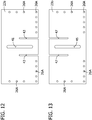
- Each of the first pair of gusset plates 23a includes a closed interior slot 41 (broadly, "elongate opening”) having an edge defining a closed loop encompassing the slot.
- the gusset plates 23a each also include a pair of open slots 43 flanking the interior slot 41 ( Fig. 12 ).
- the open slots 43 extend from a bottom of the gusset plates 23 to an interior of the gusset plates.
- Each of the second pair of gusset plates 23b includes a closed interior slot 45 (broadly, "elongate opening") of substantially the same construction as the slot 41, and a pair of open slots 47 flanking the interior slot ( Fig. 13 ).
- the open slots 47 extend from a top of the gusset plates 23 to an interior of the gusset plates.
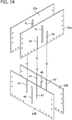
- the slots 43, 47 of the first and second pairs of gusset plates 23a, 23b allow the plates to be assembled as schematically illustrated in Fig. 14 .
- the open slots 43 of the first pair of gusset plates 23a are configured to mate with the open slots 47 of the second pair of gusset plates 23b such that portions of the first pair of gusset plates 23a are received in the open slots of the second pair of gusset plates, and portions of the second pair of gusset plates are received in the open slots of the first pair of gusset plates. In this way, the gusset plates 23a, 23b intersect and extend through each other.
- first pair of gusset plates 23a are attached to the second pair of gusset plates 23b such that top and bottom edges of the first pair of gusset plates are generally flush with respective top and bottom edges of the second pair of gusset plates 23b.
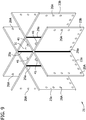
- gusset plates 23a, 23b form a collar like gusset plate assembly 21 having the appearance of a 3-dimensional pound sign defining a column passage 51, as shown in Fig. 15 .
- intersecting gusset plates 23a, 23b extend orthogonally with respect to each other.
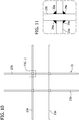
- the gusset plates 23a, 23b are welded together along vertical fillet welds 29a extending along the intersection corners between the gusset plates, which completes the gusset plate assembly 21.
- Horizontal fillet welds 29b (broadly, “first gusset plate-to-column welds”) at top and bottom edges of the gusset plates 23a, 23b extend transverse to the longitudinal axis of the column 15 and attach the gusset plate assembly 21 to the column. Additionally, fillet welds 29c (broadly, “second gusset plate-to-column welds”) in the closed slots 41, 45 in the gusset plates 23a, 23b attach the gusset plate assembly 21 to the column 15 ( Fig. 7 ).
- double parallel vertical welds extend within and along a length of each slot 41, 45 and connect at rounded ends of the slot, forming a continuous weld around the perimeter of the slots.
- the slots 41, 45 are positioned generally at a center of the column faces 20 and thus the welds 29c within the slots 41, 45 provide additional structure for enhancing the moment resisting capabilities of the structure.
- horizontal cover plates 27 are disposed on top of and attached to an end of the beams 19.
- the cover plates 27 have a width that is greater than a width of the respective beam 19 and a horizontal spacing of the associated gusset plates 23.
- the configuration of the cover plates 27 allows the beams 19 to be lowered between the gusset plates 23 so that each end of the full-length beam assembly 17 is initially supported in bearing between the cover plate 27 and the top edge of the horizontal extension of the gusset plates 23 of the column assembly 13.
- the beams 19 are self-shoring.
- the cover plates 27 may rest on a top face of a projecting horizontal leg of upper angle irons 31 attached to the gusset plates 23.
- the cover plates 27 extend along the length of their respective beams 19 and terminate just beyond the ends of the gusset plates 23.
- the cover plates 27 have an oblong radiused slot opening 30 extending along the length of the cover plate. It will be understood that the cover plates 27 may have other widths, configurations and slot-type oblong openings. For example, a cover plate (not shown) may have no slot opening 30.
- Vertical shear plates 32 are welded at 29d to the web of the beam 17 and have holes 26a for connection to the gusset plates 23a, 23b.
- the column assembly 13 is bolted to the beam assemblies 17 by bolts 26 extending through aligned bolt holes 26A in the assemblies.
- bolts 26 are used to attach the upper angle irons 31 to the cover plates 27, the lower angle irons 33 to the gusset plates 23, and the vertical shear plates 32 to the gusset plates, all through aligned bolt holes 26a in the respective components.
- the joint connection structure 11 outlined above is a bi-axial beam-to-column type structure.
- the structure 11 provides for beam assembly connection along four sides of hollow tubular column 15.
- each of the components of the joint connection structure 11, as well as the beam 19 and column 15, are made of structural steel.
- Some of the components of the joint connection structure 11 are united by welding and some by bolting. The welding may be initially performed at a fabrication shop. The bolting may be performed at the construction site, which is the preferred option in many regions of the world.
- the beam assembly 17 can be connected to the column assembly 13 in other suitable ways such as by welding, or in an all-bearing connection.
- the column assembly 13 may be fabricated at a fabrication shop and later transported to the construction site.
- the gusset plates 23 are mated with each other via the slots 43, 47 ( Figs. 14 and 15 ).
- the mated gusset plates 23 are welded to each other to form the rigid gusset plate assembly 21 ( Fig. 9 ).
- the gusset plate assembly is received on the column 15 by inserting the column in the column passage 51 of the gusset plate assembly 21.
- the column 15 can be turned on its side to facilitate the insertion of the column through the column passage 51 of the gusset plate assembly 21, and to facilitate welding of the gusset plate assembly to the faces 20 of the column.
- the gusset plate assembly 21 is then located on the column at a selected position, such as at a predetermined floor location, and welded at 29b or otherwise attached to the faces 20 of the walls of the column 15.
- the gusset plate assembly is welded to the column 15 along horizontal welds 29b located at the top and bottom of the gusset plates 23, and along welds 29c within slots 41, 45.
- the upper angle irons 31 are welded at 29f or otherwise attached to the gusset plates 23.
- the column assembly 13 can be constructed exclusively by welds.
- the welds 29 are fillet welds. Fillet welds do not require ultra-sonic inspection which results in reduced shop fabrication costs.
- the welds could be groove welds or stitch welds. Other welds and other forms of connection are also within the scope of the present disclosure.
- the full-length beam assembly 17 may also be fabricated at a fabrication shop prior to being transported to the construction site.
- the cover plates 27 are welded at 29e or otherwise attached to the upper flange of the beam. Welding (such as by weld 29e) is carried out between the periphery of the slot opening 30 and the top flange of the beam 19, and along the top flange tips of the beam on the underside of the cover plate (not shown).
- the lower angle irons 33 are welded at 29g or otherwise attached to the bottom flange of the beam 19 and project laterally outwardly from the beam. Any welds needed to form the full-length beam assembly 17 can be carried out at the shop.
- the shop permits use of fixtures and precision manufacturing techniques to form the collar like gusset plate assembly 21, the column assemblies 13 and the beam assemblies 17 in a highly accurate manner.
- the welds 29 are fillet welds. Other welds and other forms of connection are also within the scope of the present disclosure.
- the cover plate 27 and lower angle irons 33 may have other configurations than those illustrated in the current embodiment.
- the column assembly 13 is joined to the full-length beam assemblies 17.
- the column assembly 13 is first erected in a vertical orientation and the ends of the full-length beam assemblies 17 are positioned horizontally and adjacent to the column assembly, so that each end of the beams is over a respective pair of gusset plates 23.
- the full-length beam assemblies 17 are then lowered between the gusset plates 23 until the bottom surfaces of the cover plates 27 engage the top surfaces of the upper angle irons 31. This engagement initially locates and supports the full-length beam assemblies 17 on the column assembly 13 to facilitate shoring during erection.
- the bi-axial beam-to-column moment-resisting joint connection structure 11 which includes full-length beam assemblies 17, is completed exclusively through bolted connections.
- the joint connection structure 11 is constructed without the use of welds.
- the cover plates 27 are designed to transfer most, if not all, of the vertical shear load from the full-length beams 19, which may eliminate the need for vertical shear plates or vertical shear elements, while also reducing material and construction costs.
- the column assembly 13 beneficially distributes the resistance to moments applied by the beams 19 to the column 15 to all four faces 20 of the column, making it well-suited to resist bi-axial loads applied by the beams to the column, particularly in severe load events. This is made possible by the use of welded interlocked orthogonal gusset plates forming the rigid gusset plate assembly 21 that hug the sidewalls and enclose the corners of the column 15. It will be understood that a moment applied by any one or any combination of the four beams will be transmitted by the rigid gusset plate assembly 21 to locations all around the column 15.
- connection to the parallel faces 20 of the column 15 provides a force couple (principally acting in shear along the length of the welds 29b) formed by the top and bottom horizontal welds 29b (comprising a horizontal weld group) connecting the gusset plates 23b to their respective adjacent faces 20 of column 15 to resist applied moment.
- top and bottom horizontal welds 29b of the near gusset plate 23a facing the end of the beam comprise another horizontal weld group forming a resisting tension/compression force couple acting perpendicular to the near face 20 of the column 15 to resist applied moment.
- the rigid gusset plate assembly 21 also transmits the moment to the opposite face 20 of the column 15 through its connection to the far gusset plate 23a, by providing a redundant resisting tension/compression force couple (acting perpendicular to the opposite face 20) formed by the top and bottom horizontal welds 29b (comprising yet another horizontal weld group) connecting the far gusset plate 23a to the opposite face 20 to resist the applied moment.
- the column assembly is configured to provide further moment resistance unique to bi-axial moments. It can be understood that if moments are being applied to the joint column assembly from beams 19 which are orthogonally arranged with respect to each other, the resolved moment vector would not lie in a vertical plane including the longitudinal axis of either beam. Instead, the moment vector would lie in a vertical plane somewhere in between orthogonal beams 19, and would therefore urge the gusset plate assembly 21 to tilt on the column along a diagonal between the longitudinal axes of said orthogonal beams 19. In this case, adjacent, near orthogonal faces 20 of the column 15 provide cooperative moment resistance.
- the welds 29c in the vertical slots 41, 45 in the gusset plates 23a, 23b which are located at the mid-depth of the column 15 on the adjacent faces 20 orthogonal to each other, provide additional moment-resisting capacity by coupling the same vertical slot welds 29c located in their respective slots 41, 45, which act together orthogonally as a vertical weld group to provide a force couple to resist the applied bi-axial moment.
- the rigid gusset plate assembly 21 also transfers the bi-axial moments to the far orthogonal faces 20 of the column 15, which comprises another vertical weld group to provide additional cooperative moment resistance. Both the near orthogonal faces 20 and far orthogonal faces act in concert with the moment resistance force couples described in the preceding paragraph to make the column assemblies 13 and joint connection structures 11 formed using the column assemblies remarkably robust.
- load transfer redundancy can also be provided under severe load conditions by a 'push/pull' effect of opposite gusset plates 23a (facing perpendicular to the longitudinal axis of the beam) bearing against the same opposite faces 20 of the column 15 under the applied moment.
- opposing faces 20 of the column 15 cooperate to resist moment (under extreme load conditions) from one beam 19, in addition to resistance provided by the welded connection of the gusset plates 23b to the orthogonal side faces 20 of the column 15, thereby providing redundancy in resisting applied moment.
- the column assembly 13 is configured to resist applied moment in the way just described for moment applied for only one beam 19, for as many as all the four beams 19 in the joint connection structure 11 made possible by bi-axial interaction of all aforementioned load transfer mechanisms.
- Beam-to-column moment-resisting joint connection structures 11 including a column assembly 13 having a hollow tubular column 15 and the gusset plate assembly 21 described above have been shown to perform extraordinarily well during full-scale simulated earthquake testing.
- the testing included two uniaxial moment frame test specimens configured with axially-loaded thin-walled HSS columns that were moment connected to wide flange beams using all field-bolted side plate moment connection technology such as disclosed in U.S. Patent No. 9,091,065 , incorporated herein by reference.
- the HSS columns were pre-loaded axially in compression to 40% of their nominal yield strength, since axial load can have a dominant role on local buckling of HSS shapes.
- the applied axial load of 40% was selected based on a suite of parametric studies which concluded that this level of axial compression in steel moment frame columns envelopes approximately 95% of typical multi-story buildings.
- An 18" square HSS column flange width-to-wall thickness ratio (b f /t f ) for one of two test specimens was set at 21, as compared to the maximum b f /t f limit of 13.2 allowed by AISC 358 Seismic Provisions, to ascertain if local buckling will occur using the beam-to-column side plate moment connection technology described herein.
- the side plate test specimen consisting of a square 18" HSS column (HSS 18x18x3/4) having a b f /t f ratio of 21, pre-loaded with an axial compression load of 40% of its nominal yield strength, and connected to a 24" deep wide flange beam (W24x84), was cyclically loaded to ultimate beam failure with no indications of column distress.
- HSS 18x18x3/4 square 18" HSS column
- W24x84 24" deep wide flange beam
- the HSS column assembly achieved two full cycles of joint rotation at 6% radians of steel moment frame drift, compared to the industry prequalification requirement (AISC 358 Seismic Provisions) of only one full cycle at 4% radians of steel moment frame drift. Therefore, the HSS column assembly proved not only to be adequate for withstanding seismic loading, the assembly exceeded current industry standards.
- the unique geometry and stiffness of this all shop fillet-welded and all field-bolted, bi-axial, beam-to-column moment-resisting joint connection structure 11 maximizes its performance and the broadness of its design applications, including both extreme wind and moderate-to-severe seismic conditions.
- the all field-bolted joint connection structure 11 preserves the physical separation (or gap) between the end of a full-length beam 19 and the face of the column 15 made possible by the use of vertically and horizontally extended parallel gusset plates 23 that sandwich the column and the beam similar to prior designs which feature an all field fillet-welded joint connection structure; thus reducing the uncertainty of bending moment load transfer between a rigidly attached steel moment frame beam and column used in the past.
- this current bi-axial application of an all field-bolted joint connection structure 11 preserves the advantage of increased beam-to-column joint stiffness, with a corresponding increase in overall steel moment frame stiffness, which results in smaller beam sizes when the building design is controlled by lateral story drift (not member strength), and hence reduced material costs.
- this bi-axial all field-bolted joint connection structure 11 When the building design is controlled by member strength (not lateral story drift), this bi-axial all field-bolted joint connection structure 11 also reduces the beam size and the column size, and hence material quantities and cost, because its connection geometry has no net section reduction in either the beam or the column (i.e., no bolt holes through either the beam or column), thereby maintaining the full strength of the beam and column.
- full-length beams are connected to gusset plates by bolts so that the full-length beam and gusset plates are substantially free of welded connection. It will be understood that welding the full-length beam assemblies 17 to the column assembly 13 is within the scope of that aspect of the disclosure.
- the bi-axial beam-to-column moment-resisting joint connection structure 11 is shown with column 15 filled with concrete C.
- Even greater load capacity and ductility can be provided, when the column 15 is filled with concrete.
- additional ductile load carrying capacity is achieved through confining the concrete by the surrounding column section. This provides a closed jacket of steel to preclude bursting of hardened concrete when subjected to heavy axial compression.
- the concrete provides an inherent resistance to the possibility of out-of-plane buckling of the thin side walls of the column 15.
- the bi-axial beam-to-column moment-resisting joint connection structure 11 is shown with upper angle irons 28 instead of cover plates 27.
- the angle irons 28 are in the illustrated embodiment welded to the beams 19 prior to being shipped to the construction site.
- a bi-axial beam-to-column moment-resisting joint connection structure of a second embodiment is generally indicated at 111.
- the joint connection structure of the second embodiment is substantially identical to the structure 11 of the first embodiment except HSS column 15 is replaced with a built-up box column 115.
- Parts of the joint connection structure 111 of the second embodiment corresponding to those of the joint connection structure 11 of the first embodiment are given the same reference numeral plus "100". Hollow steel built-up box section columns are typically used in the design of high rise buildings, specialty structures, and residential towers.
- the bi-axial beam-to-column moment-resisting joint connection structure 111 is shown with built-up box column 115 filled with concrete C.
- a column assembly of a third embodiment is generally indicated at 213.
- the column assembly 213 of the third embodiment is substantially identical to the column assembly 13 of the first embodiment. Parts of the column assembly 213 of the third embodiment corresponding to those of the column assembly 13 of the first embodiment will be given the same reference numeral plus "200". This numbering convention is repeated in subsequent embodiments.
- the only differences between the column assembly 213 of the third embodiment and the column assembly 13 of the first embodiment is the gusset plates 223a, 223b of the gusset plate assembly 221 of the third embodiment each have a narrow closed slots 241, 245 extending vertically along the gusset plates. Further, plug welds 229c fill the narrow closed slots 241, 245.
- the plug welds 229c comprise square groove slot welds that extend along and fill the slots 241, 245 to provide proportionally reduced moment-resisting strength as compared to the fillet welds 29c in the slots 41, 45 in the first embodiment.
- the method of assembling the gusset plate assembly 221 is identical to the method of assembling the gusset plate assembly 21 of the first embodiment, and the method of constructing the column assembly 213 is otherwise identical to the method of constructing the column assembly 13 of the first embodiment. Further the column assembly 213 can be attached to full-length beam assemblies in the same fashion as column assembly 13 of the first embodiment.
- a column assembly of a fourth embodiment is generally indicated at 313.
- the column assembly 313 of the fourth embodiment is substantially identical to the column assembly 13 of the first and third embodiments.
- the only difference between the two embodiments is the removal of the closed slots 41, 45 in the gusset plates.
- the method of assembling the gusset plate assembly 321 is identical to the method of assembling the gusset plate assembly 21 of the first embodiment, and the method of constructing the column assembly 313 is otherwise identical to the method of constructing column assembly 13 of the first embodiment.
- the primary difference being that the gusset plate assembly 313 is not welded to the column 315 within vertical slots in the gusset plates 323. Further, the column assembly 313 can be attached to full-length beam assemblies in the same fashion as column assembly 13 of the first embodiment.
- a column assembly of a fifth embodiment is generally indicated at 413.
- the column assembly 413 of the fifth embodiment is similar to the column assembly 313 of the fourth embodiment.
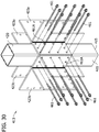
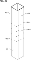
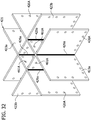
- the primary difference between the two embodiments is gusset plate assembly 421 is attached to column 415 by a threaded through-rod connection, instead of being welded to the column.
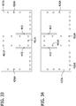
- threaded rods 461 extend through aligned rod holes 461A in the gusset plates 423 and the column 415 to secure the gusset plate assembly 421 to the column 415.
- Each planar face 420 of the column 415 includes rod holes 461A.
- Each rod hole in a face 420 of the column 415 is axially aligned with a rod hole in an opposing face 420 of the column.
- the gusset plates 423 have oversized rod holes 461A configured to align with the standard rod holes 461A in the column 415.
- the threaded rods 461 extend through vertically aligned oversized rod holes 461A in the gusset plates 423 and the rod holes 461 in opposing faces of the column 415.
- the column 415 can be turned on its side to more easily facilitate insertion of the threaded rods 461.
- Rod holes 461A in adjacent faces of the column 415, and their corresponding oversized rod holes 461A in the gusset plates 423, are axially offset from each other so that the threaded rods 461 extending through the adjacent sides of the column assembly will not interfere with each other.
- the rod holes 461A are arranged in a rectangular pattern on the faces of the column 415 and the gusset plates 423.
- the rod holes 461A could be arranged in a different pattern without departing from the scope of the disclosure.
- the gusset plate assembly 421 is also attached to the column 415 by top and bottom horizontal welds 429b.
- welds 429b may be omitted within the scope of the present invention.
- expansion bolts (not shown) may be used in place of the threaded rods 461.
- the expansion bolts would not extend across the column 419, but instead would expand to bear against an inner face of the wall of the column through which the expansion bolt is passed.
- different bolts would be used on all four faces 420 of the column 415.
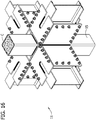
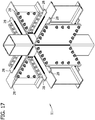
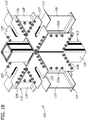
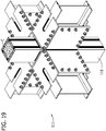
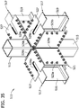
- a bi-axial beam-to-column moment-resisting joint connection structure including a column assembly 513 of a sixth embodiment is generally indicated at 511.
- the joint connection structure may be used in the construction of a building framework.
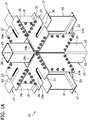
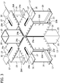
- the joint connection joins column assembly 513 including a column 515 to three full-length beam assemblies 517 including full-length beams 519.
- the column assembly 513 is similar to the column assembly 313 of the fourth embodiment but includes a modification to the gusset plate assembly 521 to configure the column assembly for attaching three beam assemblies 517.
- the gusset plate assembly 521 comprises a plurality of gusset plates 523 connected to the column 515 and extending laterally outward from the column.
- the gusset plates 523 extend within planes generally parallel to a longitudinal axis of the column 515.
- a first pair of spaced apart parallel, vertically and horizontally extending gusset plates 523a sandwich the column 515 and co-axially extending beams 519.
- the first pair of gusset plates 523a extends laterally outward from the column 515 in opposite directions along a first axis and defines spaces on opposite sides of the column for receiving end portions of beams 519 for mounting respective beam assemblies 517 to the column assembly 513 via the gusset plate assembly 521.
- a second pair of spaced apart parallel, vertically and horizontally extending gusset plates 523b sandwich the column 515 and a beam 519 extending orthogonally to the co-axially extending beams.
- the second pair of gusset plates 523b extends laterally outward from the column 515 in opposite directions along a second axis extending orthogonally to the first axis.
- the second pair of gusset plates 23b defines a space for receiving an end portion of beam 519 for mounting a beam assembly 517 to the column assembly 513 via the gusset plate assembly 521.
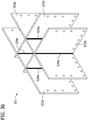
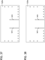
- the first pair of gusset plates 523a each includes a pair of open slots 543 extending from an edge of the gusset plates 523a to an interior of the gusset plates ( Figs. 37 and 38 ).
- the slots 543 are symmetrically spaced about a vertically extending centerline of the gusset plates 523a.
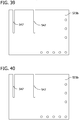
- the second pair of gusset plates 523b each includes a pair of open slots 547 extending from an edge of the gusset plates 523b to an interior of the gusset plates ( Figs. 39 and 40 ).
- the slots 547 are asymmetrically spaced about a vertically extending centerline of the gusset plates 523b.
- slots 547 are laterally spaced from a vertically extending centerline of the gusset plate 523b toward one side of the gusset plate. Therefore the gusset plate 523b extends a greater distance from one of the slots 547, away from the other slot, than it extends from the other slot in an opposite direction.
- the open slots 543 of the first pair of gusset plates 523a are configured to mate with the open slots 547 of the second pair of gusset plates 523b such that portions of the first pair of gusset plates 523a are received in the open slots of the second pair of gusset plates, and portions of the second pair of gusset plates are received in the open slots of the first pair of gusset plates.
- the connected gusset plates 523a, 523b form gusset plate assembly 521 ( Fig. 36 ).
- the gusset plates 523a, 523b are welded together along vertical fillet welds 529a extending along the intersecting corners between the gusset plates, substantially as shown in Fig. 11 for the first embodiment.
- gusset plates 523b extend beyond the intersecting gusset plate 523a to form a controlled rigid intersection of orthogonal gusset plates that can then be welded at four locations (such as shown in Fig. 11 ). It is understood, however, that a free vertical edge of gusset plate 523b can be made to flush up to the interior face of rearwardmost orthogonal gusset plate 523a of Fig. 36 , and be welded to the face of the gusset plate without the need of a slotted interconnected interface. In that case, the slots 547 nearest the edge of the gusset plates 523b in Fig.
- Horizontal fillet welds 529b at top and bottom edges of the gusset plates 523a, 523b attach the gusset plate assembly 521 to the column 515.
- the first pair of gusset plates 523a are attached to the second pair of gusset plates 523b such that top and bottom edges of the first pair of gusset plates are generally flush with respective top and bottom edges of the second pair of gusset plates 523b. It may be seen that the gusset plate assembly 521 forms only three spaces for receiving end portions of beam assemblies.
- the method of assembling the gusset plate assembly 521 is identical to the method of assembling the gusset plate assembly 321 of the fourth embodiment, and the method of constructing the column assembly 513 is otherwise identical to the method of constructing the column assembly 313 of the fourth embodiment. Further the column assembly 513 can be attached to full-length beam assemblies in the same fashion as column assembly 313 of the fourth embodiment.
- a bi-axial beam-to-column moment-resisting joint connection structure including a column assembly 613 of a seventh embodiment is generally indicated at 611.
- the joint connection structure may be used in the construction of a building framework.
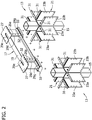
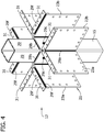
- the joint connection joins column assembly 613 including a column 615 to two full-length beam assemblies 617 including full-length beams 619.
- the column assembly 613 is similar to the column assembly 313 of the fourth embodiment but includes a modification to the gusset plate assembly 621 to configure the column assembly for attaching two orthogonal beam assemblies 617.
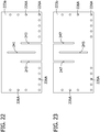
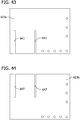
- Each of a first pair of gusset plates 623a includes two open slots 643 extending from an edge of the gusset plates 623a to an interior of the gusset plates ( Fig. 43 ).
- the slots 643 are asymmetrically spaced about a vertically extending centerline of the gusset plates 623a.
- slots 643 are laterally spaced from a vertically extending centerline of the gusset plate 623a toward one side of the gusset plate.
- Each of the second pair of gusset plates 623b includes two open slots 647 extending from an edge of the gusset plates 623b to an interior of the gusset plates ( Fig. 44 ).
- the slots 647 are also asymmetrically spaced about a vertically extending centerline of the gusset plates 623b in a similar fashion to the slots 643 in the first pair of gusset plates 623a.
- the open slots 643 of the first pair of gusset plates 623a are configured to mate with the open slots 647 of the second pair of gusset plates 623b such that portions of the first pair of gusset plates 623a are received in the open slots of the second pair of gusset plates, and portions of the second pair of gusset plates are received in the open slots of the first pair of gusset plates.
- the connected gusset plates 623a, 623b form gusset plate assembly 621.
- the gusset plate assembly provides only two spaces for receiving ends of the beam assemblies 617.
- the gusset plates 623a, 623b are welded together along vertical fillet welds 629a extending along the intersection corners between the gusset plates.
- gusset plates 623b extend beyond the intersecting gusset plate 623a to form a controlled rigid intersection of orthogonal gusset plates that can then be welded at four locations (such as shown in Fig. 11 ). It is understood, however, that a free vertical edge of gusset plate 623b can be made to flush up to the interior face of rearwardmost orthogonal gusset plate 623a of Fig. 42 , and be welded to the face of the gusset plate without the need of a slotted interconnected interface. In that case, the slots 647 nearest the edge of the gusset plates 623b in Fig.
- Horizontal fillet welds 629b at top and bottom edges of the gusset plates 623a, 623b attach the gusset plate assembly 621 to the column 615.
- the first pair of gusset plates 623a are attached to the second pair of gusset plates 623b such that top and bottom edges of the first pair of gusset plates are generally flush with respective top and bottom edges of the second pair of gusset plates 623b.
- the method of assembling the gusset plate assembly 621 is identical to the method of assembling the gusset plate assembly 321 of the fourth embodiment, and the method of constructing the column assembly 613 is otherwise identical to the method of constructing the column assembly 313 of the fourth embodiment. Further the column assembly 613 can be attached to full-length beam assemblies in the same fashion as column assembly 313 of the fourth embodiment.
- a column assembly of an eighth embodiment is generally indicated at 713.
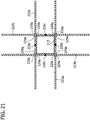
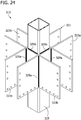
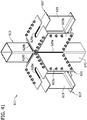
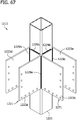
- the gusset plate assembly 721 of the eighth embodiment comprises a plurality (four) of gusset plate subassemblies 771 separately welded to column 715. Each subassembly 771 hugs its two adjacent orthogonal faces 720 of the column 715, thereby enclosing the corner of the column, and is welded to the column.
- the gusset plate subassemblies each include a first gusset plate 723a and a second gusset plate 723b.
- Facing surfaces of adjacent gusset plates 723a, 723b define the spaces for receiving end portions of a beam for mounting a beam assembly to the column assembly 713 via the gusset plate assembly 721.
- the column assembly 713 can be attached to full-length beam assemblies in the same fashion as column assembly 13 of the first embodiment.
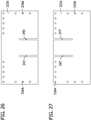
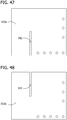
- Each subassembly 771 comprises the first gusset plate 723a having an open slot 743 located closer to one side of the first gusset plate ( Fig. 47 ), and the second gusset plate 723b having an open slot 747 located closer to one side of the second gusset plate ( Fig. 48 ).
- the gusset plates 723a, 723b are attached by mating the slots 743, 747 with each other and welding the gusset plates 723a, 723b together at vertical welds 729a extending along the intersection corners between the gusset plates.
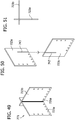
- the assembled gusset plate subassemblies 771 have an unsymmetrical, crossed configuration (see, Figs. 49 and 51 ).
- the portions of the gusset plates 723a, 723b that define a smaller section are welded to the four corners of the column 715, and the portions of the gusset plates that define a larger section extend laterally outward from the column.
- the subassemblies 771 are welded to each face 720 of the column 715 along top and bottom horizontal welds 729b and vertical welds 729c. It will be understood that other forms of connection of the subassemblies 771 to the column 715 may be employed.
- the gusset plates 723a, 723b and column 715 may have bolt holes and receive suitable fasteners such as expansion bolts to mount the subassemblies on the column.
- the gusset plate assembly 721 beneficially distributes the resistance to moments applied by the beams (not shown) to the column 715 to all four faces 720 of the column, making it also well-suited to resist bi-axial loads applied by the beams to the column.
- This is made possible by the use of welded interlocked orthogonal gusset plates 723a, 723b forming the rigid gusset plate subassemblies 771 that hug the sidewalls and can be configured to enclose all four corners of the column 715 to resist bi-axial applied moment. It will be understood that a moment applied by any one or any combination of the four beams will be transmitted by pairs of gusset plate subassemblies 771 to locations all around the column 715.
- the subassemblies 771 are welded to the faces 720 of the column 715 along top and bottom horizontal welds 729b and vertical welds 729c.
- the subassemblies 771 cooperate to distribute load to the faces 720 of the column 715.
- a moment is applied to one of the subassemblies 771 ( Fig. 49 ), by a beam (not shown) connected to gusset plates 723b, it is resisted by top and bottom horizontal welds 729b and vertical weld 729c which comprise a channel-shaped weld group configuration capable of transferring in-plane moment to an adjacent face 720 of column 715 parallel to the axis of the beam.
- This in-plane moment transfer to the face 720 of the column 715 is similar to the in-plane moment transfer described in U.S. Patent Nos.
- top and bottom welds 729b and vertical welds 729c of the subassembly 771 having a gusset plate 723a extending transverse to the longitudinal axis of the beam and connected to the near face 720 also resist the moment, forming a tension/compression force couple to transfer moment out- of-plane to the face of the column.
- welds 729b and 729c (comprising a channel-shaped weld group configuration) connect the gusset plate 723a to the near face 720 of column 715 and are capable of resisting applied out-of-plane moment via tension/compression force couple acting perpendicular to the near face of the column.
- additional moment resisting capacity is provided in the case of a bi-axially applied moment, where the resolved moment vector would lie between two orthogonal beams and tend to tilt the gusset plate subassembly 771 on the column 715 along a diagonal between the longitudinal axes of the beams.
- the vertical welds 729c connecting the vertical edges of the gusset plates 723b, 723a to adjacent orthogonal faces 720 of the column 715 act together orthogonally as a vertical weld group to provide a force couple to resist the applied bi-axial moment. It will be appreciated that all of the subassemblies 771 may act in this manner to resist bi-axially applied moment, enclosing as many as all four corners of column 715 to act in concert with the aforementioned moment resistance force couples to make the column assembly 713 and a joint connection structure formed using the column assembly remarkably robust.
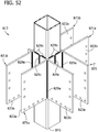
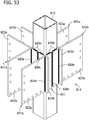
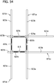
- a column assembly of a ninth embodiment is generally indicated at 813.
- the column assembly 813 of the ninth embodiment is similar to the column assembly 713 of the eighth embodiment but includes a modification to the gusset plate assembly 821 to configure the column assembly 813 for attaching three beam assemblies.
- each subassembly 871 hugs its two adjacent orthogonal faces 820 of the column 815, thereby enclosing the corner of the column, and is welded to the column.
- gusset plate assembly 821 of the ninth embodiment comprises two gusset plate subassemblies 871 a and 871 b of different construction.
- Second subassembly 871 b comprises a first gusset plate 823a having an open slot 843 located closer to one side of the first gusset plate, and a second gusset plate 823b having an open slot 847 located closer to one side of the second gusset plate.
- the second gusset plate 823b of the second subassembly 871 b is smaller than the first gusset plate 823a and has no holes for bolts or threaded rods.
- the gusset plates 823a, 823b are attached by mating the slots 843, 847 with each other and welding the gusset plates 823a, 823b together at vertical welds 829a extending along the intersection corners between the gusset plates.
- the assembled second gusset plate subassemblies 871 b have an unsymmetrical cross configuration. Portions of the gusset plates 823a, 823b that define a top section of the cross are welded to two adjacent corners of the column 815, and portions of the gusset plates that define a bottom section of the cross extend laterally outward from the column.
- Facing surfaces of adjacent gusset plates 823a, 823b define the spaces for receiving end portions of a beam for mounting a beam assembly to the column assembly 813 via the gusset plate assembly 821.
- the column assembly 813 can be attached to full-length beam assemblies in the same fashion as column assembly 13 of the first embodiment.
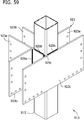
- a column assembly of a tenth embodiment is generally indicated at 913.
- the column assembly 913 of the tenth embodiment is similar to the column assembly 713 of the eighth embodiment but includes a modification to the gusset plate assembly 921 to configure the column assembly for attaching three beam assemblies.
- the primary difference between the two embodiments is gusset plate assembly 921 of the tenth embodiment, in addition to the pair of gusset plate subassemblies 971, includes a separate gusset plate 923c (also forming part of the gusset plate assembly 921) that is not mated with another gusset plate.
- Subassemblies 971 are similar to the subassemblies 771 in the eighth embodiment.
- each subassembly 971 hugs its two adjacent orthogonal faces 920 of the column 915, thereby enclosing the corner of the column, and is welded to the column.
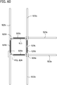
- the portion of the gusset plate 923a overlying the face 920 of the column 915 is longer than the portions of the gusset plates 923b (see, Fig. 60 ).
- the subassemblies 971 are welded to adjacent corners of the column 915.
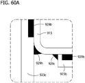
- the separate gusset plate 923c is welded to an opposite face of the column 915 by top and bottom horizontal welds 929b, vertical welds 929c, as well as by an internal, vertical corner flare bevel weld 929h (see, Fig. 60A ). Facing surfaces of adjacent gusset plates 923a, 923a of the subassemblies 971 define a space for receiving an end portion of a beam for mounting a beam assembly to the column assembly 913 via the gusset plate assembly 921. Further, facing surfaces of gusset plates 923b and 923c define spaces for receiving end portions of beams for mounting beam assemblies to the column assembly 913.
- the column assembly 913 can be attached to full-length beam assemblies in the same fashion as column assembly 13 of the first embodiment.
- a column assembly of an eleventh embodiment is generally indicated at 1013.
- the column assembly 1013 of the eleventh embodiment is similar to the column assembly 913 of the tenth embodiment but instead of a single gusset plate 923c, column assembly 1013 includes two separate gusset plates 1023d and 1023e.
- Subassemblies 1071 are identical to the subassemblies 971 in the tenth embodiment. Each of the subassemblies 1071 are welded to adjacent corners of the column 1015, and hugs its two adjacent orthogonal faces 1020 of the column, thereby enclosing the corner of the column.
- the separate gusset plates 1023d, 1023e are welded to the column using vertical welds 1029c.
- the corner welds 929e used in the tenth embodiment, are not used in the eleventh embodiment.
- Facing surfaces of adjacent gusset plates 1023a, 1023a of the subassemblies 1071 define a space for receiving an end portion of a beam for mounting a beam assembly to the column assembly 1013 via the gusset plate assembly 1021.
- facing surfaces of gusset plates 1023b and 1023d, and facing surfaces of 1023b and 1023e defines spaces for receiving end portions of beams for mounting beam assemblies to the column assembly 1013.
- the column assembly 1013 can be attached to full-length beam assemblies in the same fashion as column assembly 13 of the first embodiment.
- a column assembly of a twelfth embodiment is generally indicated at 1113.
- the column assembly 1113 of the twelfth embodiment is similar to the column assembly 813 of the ninth embodiment but includes a modification to the gusset plate assembly 821 to configure the column assembly for attaching two beam assemblies.
- a first subassembly 1171 a is identical to the subassemblies 771 in the eighth embodiment.
- Second subassemblies 1171 b are identical to the second subassemblies 871 b of the ninth embodiment.
- Facing surfaces of adjacent gusset plates 1123a, 1123b, and adjacent gusset plates 1123a, 1123a, define spaces for receiving end portions of beams for mounting beam assemblies to the column assembly 1113 via the gusset plate assembly 1121.
- the column assembly 1113 can be attached to full-length beam assemblies in the same fashion as column assembly 13 of the first embodiment.
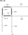
- a column assembly of a thirteenth embodiment is generally indicated at 1213.
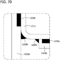
- the column assembly 1213 of the thirteenth embodiment is similar to the column assembly 1113 of the twelfth embodiment but instead of having the two second subassemblies 1171 b, column assembly 1213 includes two single gusset plates 1223d and 1223e.
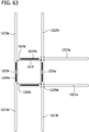
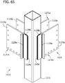
- Subassembly 1271 is similar to the subassemblies 771 in the eighth embodiment, but the portions of the gusset plates 1223a, 1223b adjacent the faces 1220 of the column 1215 extending over more than half the widths of the faces..
- the single gusset plates 1223d, 1223e are attached to the column 1215 using vertical and horizontal welds 1229b, 1229c and corner flare bevel welds 1229h. Facing surfaces of adjacent gusset plates 1223a and 1123d, and facing surfaces of gusset plates 1223b and 1223e define the spaces for receiving end portions of beams for mounting beam assemblies to the column assembly 1213 via the gusset plate assembly 1221.
- the column assembly 1213 can be attached to full-length beam assemblies in the same fashion as column assembly 13 of the first embodiment.
- Bi-axial, moment resisting beam-to-column joint connection structures and column assemblies that are constructed according to the principles of the present invention provide numerous unique features, benefits and advantages. Reference is made to the figures illustrating some of the embodiments to which the advantages and benefits apply.
Landscapes
- Engineering & Computer Science (AREA)
- Architecture (AREA)
- Physics & Mathematics (AREA)
- Electromagnetism (AREA)
- Civil Engineering (AREA)
- Structural Engineering (AREA)
- Joining Of Building Structures In Genera (AREA)
Applications Claiming Priority (1)
| Application Number | Priority Date | Filing Date | Title |
|---|---|---|---|
| US15/144,414 US20170314254A1 (en) | 2016-05-02 | 2016-05-02 | Moment resisting bi-axial beam-to-column joint connection |
Publications (2)
| Publication Number | Publication Date |
|---|---|
| EP3241952A1 true EP3241952A1 (de) | 2017-11-08 |
| EP3241952B1 EP3241952B1 (de) | 2022-06-08 |
Family
ID=58632216
Family Applications (1)
| Application Number | Title | Priority Date | Filing Date |
|---|---|---|---|
| EP17167418.7A Active EP3241952B1 (de) | 2016-05-02 | 2017-04-20 | Momentbeständiger biaxialer träger-säulen-knotenpunkt |
Country Status (6)
| Country | Link |
|---|---|
| US (2) | US20170314254A1 (de) |
| EP (1) | EP3241952B1 (de) |
| JP (1) | JP7090404B2 (de) |
| AU (1) | AU2017202780B2 (de) |
| CA (1) | CA2965456C (de) |
| MX (1) | MX2017005717A (de) |
Cited By (1)
| Publication number | Priority date | Publication date | Assignee | Title |
|---|---|---|---|---|
| WO2019102299A1 (en) * | 2017-11-27 | 2019-05-31 | Energia W Kogeneracji Ewk Spolka Akcyjna | Anchoring unit |
Families Citing this family (45)
| Publication number | Priority date | Publication date | Assignee | Title |
|---|---|---|---|---|
| CA2898340C (en) | 2012-11-30 | 2018-02-13 | Mitek Holdings, Inc. | Gusset plate connection of beam to column |
| US10501929B2 (en) * | 2013-09-30 | 2019-12-10 | Drew P. HENRY | Hollow connector sleeve with interlocking components |
| US20160356033A1 (en) * | 2015-06-03 | 2016-12-08 | Mitek Holdings, Inc | Gusset plate connection of braced beam to column |
| CN105369898B (zh) * | 2015-08-25 | 2017-10-13 | 河南奥斯派克科技有限公司 | 基于bim的薄壁槽钢组合房屋 |
| US10006212B2 (en) * | 2015-11-24 | 2018-06-26 | Sheng-Liang Chen | Assembled house |
| US20180238041A1 (en) | 2017-02-21 | 2018-08-23 | Styrc Jacek | Modular furniture system |
| US10859103B2 (en) * | 2017-04-11 | 2020-12-08 | Caterpillar Inc. | Weld joint assembly |
| WO2019038602A1 (en) * | 2017-08-19 | 2019-02-28 | Mohammad Ramezani | FRAME RESISTANT TO THE MOMENT |
| US20190136504A1 (en) * | 2017-11-08 | 2019-05-09 | Modular Steel Solutions, LLC | Apparatus and systems related to modular construction |
| USD887025S1 (en) | 2017-11-17 | 2020-06-09 | 2724889 Ontario Inc. | Connector for a modular structure |
| US10370856B2 (en) * | 2017-12-15 | 2019-08-06 | Platform Manufacturing Group | Modular stair system |
| JP7343509B2 (ja) | 2018-02-09 | 2023-09-12 | コンクステック,インコーポレーテッド | フルモーメント連結カラーシステム |
| CN108797798A (zh) * | 2018-07-09 | 2018-11-13 | 元氏县蟠山型材结构厂 | 钢结构梁柱固定节点及固定套筒的加工方法 |
| CN109162348A (zh) * | 2018-10-17 | 2019-01-08 | 苏州昆仑绿建木结构科技股份有限公司 | 一种带预应力增强箱梁的装配式竹空心框架结构 |
| US10745901B2 (en) * | 2018-11-21 | 2020-08-18 | Steel Worx Solutions LLC | System and method of constructing a multi-story building utilizing modular components |
| CN109853739B (zh) * | 2019-02-27 | 2020-06-23 | 青岛理工大学 | 装配式钢木组合节点 |
| US11434633B2 (en) * | 2019-05-31 | 2022-09-06 | Charles Post | System and associated methods for multistory building construction |
| CN110644619B (zh) * | 2019-09-21 | 2020-10-09 | 青岛理工大学 | 装配式限位增强钢木磨砂套筒组合节点 |
| CN110965639B (zh) * | 2019-10-12 | 2021-02-23 | 中国建筑股份有限公司 | 一种预制装配干式连接框架结构体系及其施工方法 |
| CN110984374B (zh) * | 2019-12-05 | 2021-05-14 | 上海绿地建设(集团)有限公司 | 一种异形柱梁柱节点结构 |
| USD936859S1 (en) | 2020-02-04 | 2021-11-23 | 2724889 Ontario Inc. | Connector |
| USD952384S1 (en) | 2020-02-04 | 2022-05-24 | 2724889 Ontario Inc. | Leg |
| USD938772S1 (en) | 2020-02-04 | 2021-12-21 | 2724889 Ontario Inc. | Connector |
| USD938771S1 (en) | 2020-02-04 | 2021-12-21 | 2724889 Ontario Inc. | Connector |
| USD938770S1 (en) | 2020-02-04 | 2021-12-21 | 2724889 Ontario Inc. | Connector |
| USD952382S1 (en) | 2020-02-04 | 2022-05-24 | 2724889 Ontario Inc. | Table |
| WO2021168371A1 (en) * | 2020-02-19 | 2021-08-26 | Conxtech, Inc. | Modular pipe rack system |
| USD936861S1 (en) | 2020-08-12 | 2021-11-23 | 2724889 Ontario Inc. | Connector for a modular structure |
| USD938619S1 (en) | 2020-08-12 | 2021-12-14 | 2724889 Ontario Inc. | Connector for a modular structure |
| USD939106S1 (en) | 2020-08-12 | 2021-12-21 | 2724889 Ontario Inc. | Connector for a modular structure |
| USD936246S1 (en) | 2020-08-12 | 2021-11-16 | 2724889 Ontario Inc. | Connector for a modular structure |
| USD936247S1 (en) | 2020-08-12 | 2021-11-16 | 2724889 Ontario Inc. | Connector for a modular structure |
| USD939731S1 (en) | 2020-08-12 | 2021-12-28 | 2724889 Ontario Inc. | Connector for a modular structure |
| USD938068S1 (en) | 2020-08-12 | 2021-12-07 | 2724889 Ontario Inc. | Connector for a modular structure |
| CN112282050A (zh) * | 2020-09-21 | 2021-01-29 | 泉州市元通科技服务有限公司 | 一种可对连接处锁紧的装配式建筑钢结构 |
| CN112832575B (zh) * | 2020-12-28 | 2022-07-12 | 浙江天然建筑设计有限公司 | 一种预制装配式混凝土建筑及其设计方法 |
| US11959270B1 (en) * | 2021-04-16 | 2024-04-16 | Morse Distribution, Inc. | Stud rail systems and methods for use in reinforced concrete structures |
| US20220412072A1 (en) * | 2021-05-12 | 2022-12-29 | Arup IP Management Ltd. | Connection system for volumetric modular construction |
| CN114673255B (zh) * | 2022-03-12 | 2025-01-03 | 宝通钢构(山东)有限公司 | 一种抗压减震效果好的钢结构 |
| US20240117577A1 (en) * | 2022-10-11 | 2024-04-11 | The Henry Group | Lightweight bridge structure and structural joint design |
| CN115787852B (zh) * | 2022-11-22 | 2023-09-05 | 中国建筑设计研究院有限公司 | 一种十字形支撑柱的刚接节点连接结构及其系统 |
| CN116335271B (zh) * | 2023-03-02 | 2025-09-19 | 中建二局安装工程有限公司 | 一种内外双腹杆复杂节点大跨度转换桁架及其工法 |
| CN117123955A (zh) * | 2023-08-09 | 2023-11-28 | 中建钢构股份有限公司 | 钢节点的制造方法及钢节点 |
| US20250269469A1 (en) * | 2024-02-26 | 2025-08-28 | Taiwan Mask Corporation | Thick steel plate assembly welded by laser welding and laser welding method thereof |
| CN119332929B (zh) * | 2024-10-31 | 2025-10-24 | 中国一冶集团有限公司 | 免二次植筋支模构造柱的主体结构施工方法 |
Citations (6)
| Publication number | Priority date | Publication date | Assignee | Title |
|---|---|---|---|---|
| GB1421040A (en) * | 1972-04-10 | 1976-01-14 | Grp Dinteret Economique Pour L | Metal construction device and method of using said device |
| US6138427A (en) | 1998-08-28 | 2000-10-31 | Houghton; David L. | Moment resisting, beam-to-column connection |
| FR2821395A1 (fr) * | 2001-02-23 | 2002-08-30 | Atroisaxe | Piece a fixation pour plates-formes de stockage et/ou de bureau |
| US7178296B2 (en) | 2004-03-19 | 2007-02-20 | Houghton David L | Structural joint connection providing blast resistance and a beam-to-beam connection resistant to moments, tension and torsion across a column |
| US8146322B2 (en) | 2008-08-21 | 2012-04-03 | Mitek Holdings, Inc. | Building structure, method of making, and components |
| US9091065B2 (en) | 2012-11-30 | 2015-07-28 | Columbia Insurance Company | Gusset plate connection of beam to column |
Family Cites Families (90)
| Publication number | Priority date | Publication date | Assignee | Title |
|---|---|---|---|---|
| US674752A (en) * | 1900-10-29 | 1901-05-21 | Ball Bearing Shade Roller Company | Extensible shade-roller. |
| GB717744A (en) | 1950-08-16 | 1954-11-03 | Hills West Bromwich Ltd | Improvements in, or relating to, stanchions for use in the erection of skeleton frameworks of buildings |
| US2868568A (en) * | 1958-04-29 | 1959-01-13 | Reinhold A Frye | Knock down structures |
| US3203150A (en) | 1961-02-27 | 1965-08-31 | Electrolux Ab | Building framework |
| US3382634A (en) * | 1966-01-07 | 1968-05-14 | Montague Betts Company Inc | Shear head |
| US3691712A (en) | 1969-05-13 | 1972-09-19 | Monsanto Co | Damping system |
| US3716957A (en) | 1970-10-23 | 1973-02-20 | J Bernardi | Column flange and stiffener plate construction |
| BE794273A (fr) * | 1972-01-28 | 1973-05-16 | World Inventions Ltd | Dispositifs pour controler l'erosion du sol |
| GB1432241A (en) * | 1972-04-19 | 1976-04-14 | Industrialised Building System | Structural building panels |
| CH548533A (de) | 1972-08-16 | 1974-04-30 | Bbc Brown Boveri & Cie | Verfahren zur herstellung einer leitschaufel fuer eine axial durchstroemte turbomaschine. |
| JPS4959307U (de) * | 1972-08-30 | 1974-05-24 | ||
| US3952472A (en) * | 1972-10-05 | 1976-04-27 | Boehmig Robert L | Joint for transferring bending moments |
| US3855748A (en) * | 1972-12-15 | 1974-12-24 | J Thomas | Playground assembly set |
| US3914063A (en) * | 1973-05-24 | 1975-10-21 | Unistrut Corp | Space frame connecting fixture |
| US4014089A (en) * | 1975-02-21 | 1977-03-29 | Kajima Corporation | Method of connecting beams and columns of steel frame construction |
| GB2036235B (en) * | 1978-11-14 | 1982-11-24 | Menelaou X | Assembly of hollow elongate members |
| US4441289A (en) | 1980-05-07 | 1984-04-10 | Takenaka Komuten Co., Ltd. | Earthquake-resistant reinforcement structure for an existing building with compression braces or tension braces |
| US4409765A (en) | 1980-06-24 | 1983-10-18 | Pall Avtar S | Earth-quake proof building construction |
| CA1178775A (en) * | 1982-09-28 | 1984-12-04 | Luc Trudeau | Dismantable joint arrangement |
| US4551960A (en) * | 1983-02-14 | 1985-11-12 | Fleishman Gregg R | Space frame structural system |
| US4863305A (en) * | 1987-10-19 | 1989-09-05 | Schold John A | Orthogonal construction joint |
| LU87320A1 (fr) | 1988-08-24 | 1990-03-13 | Arbed | Charpente metallique antisismique |
| US5244300A (en) | 1991-02-28 | 1993-09-14 | Lehigh University | Structural connector approximating a cone of elliptical cross-section |
| JP2961455B2 (ja) * | 1991-07-23 | 1999-10-12 | 株式会社竹中工務店 | 鉄骨構造体の仕口およびその製作法 |
| JP3426359B2 (ja) | 1994-08-16 | 2003-07-14 | 株式会社建築資料研究社 | 梁乃至桁接合用具及びそれと組合せて用いる車知栓 |
| US5660017A (en) | 1994-12-13 | 1997-08-26 | Houghton; David L. | Steel moment resisting frame beam-to-column connections |
| US7047695B2 (en) * | 1995-04-11 | 2006-05-23 | Seismic Structural Design Associates, Inc. | Steel frame stress reduction connection |
| US5680738A (en) | 1995-04-11 | 1997-10-28 | Seismic Structural Design Associates, Inc. | Steel frame stress reduction connection |
| US6237303B1 (en) | 1995-04-11 | 2001-05-29 | Seismic Structural Design | Steel frame stress reduction connection |
| JP3284877B2 (ja) | 1995-04-26 | 2002-05-20 | 日本鋼管株式会社 | 角形鋼管柱とh形断面梁の接合構造 |
| US6073405A (en) | 1995-12-22 | 2000-06-13 | Icf Kaiser Engineers, Inc. | Fitting for effecting bolted connection between a beam and a column in a steel frame structure |
| US5680737A (en) * | 1996-02-16 | 1997-10-28 | Sheipline; Gary D. | Structural connector hub for exhibit booths |
| JPH10227063A (ja) * | 1996-12-12 | 1998-08-25 | Nkk Corp | 角形鋼管柱とh形断面梁の接合構造 |
| JPH10292491A (ja) | 1997-04-18 | 1998-11-04 | Ig Tech Res Inc | 木造建築における柱横架材の接合工法及び継手板構造 |
| JPH10317491A (ja) | 1997-05-21 | 1998-12-02 | Kowa:Kk | 柱材の接合構造 |
| JP3080911B2 (ja) * | 1997-09-29 | 2000-08-28 | ゼンテリア株式会社 | 重量鉄骨構造による建物構造体における柱型・梁材の接合工法 |
| US6022165A (en) | 1997-10-30 | 2000-02-08 | Simpson Strong-Tie Company, Inc. | Rigid internal connector |
| JPH11200489A (ja) | 1997-11-13 | 1999-07-27 | Kawasaki Steel Corp | 接合金物付鋼管柱および環状接合金物 |
| US6516583B1 (en) | 1999-03-26 | 2003-02-11 | David L. Houghton | Gusset plate connections for structural braced systems |
| US7114300B1 (en) | 1999-05-07 | 2006-10-03 | Smart Furniture | Modular construction system |
| JP2000336772A (ja) | 1999-05-25 | 2000-12-05 | Hitachi Metals Ltd | 外ダイアフラム |
| JP2002013203A (ja) | 2000-06-29 | 2002-01-18 | Uesuto:Kk | 木造建築物の接合構造 |
| US20020124520A1 (en) * | 2001-02-08 | 2002-09-12 | Arcmatic Integrated Systems, Inc. | Moment resisting connection apparatus and method |
| US7497054B2 (en) | 2001-06-06 | 2009-03-03 | Nippon Steel Corporation | Column-and-beam join structure |
| JP2002371627A (ja) | 2001-06-14 | 2002-12-26 | Nippon Steel Corp | 鋼製柱と鋼製梁との接合構造 |
| US6591573B2 (en) * | 2001-07-12 | 2003-07-15 | David L. Houghton | Gusset plates connection of beam to column |
| JP2003049558A (ja) | 2001-08-07 | 2003-02-21 | Kazuhiko Kasai | 制振間柱 |
| US6837016B2 (en) * | 2001-08-30 | 2005-01-04 | Simmons Robert J | Moment-resistant building frame structure componentry and method |
| JP4693305B2 (ja) | 2001-08-31 | 2011-06-01 | 新日本製鐵株式会社 | 摩擦ダンパーを有するh形断面材の高力ボルト接合構造 |
| US6986204B2 (en) | 2002-03-13 | 2006-01-17 | Glenn Joseph K | Method of constructing panelized roof structures |
| US6993880B2 (en) | 2002-11-01 | 2006-02-07 | Keymark Enterprises, Llc | Apparatuses and methods for manufacture and placement of truss assemblies |
| US7146770B2 (en) * | 2002-11-05 | 2006-12-12 | Simmons Robert J | Angle-section column-beam connector |
| US6837010B2 (en) | 2002-12-05 | 2005-01-04 | Star Seismic, Llc | Pin and collar connection apparatus for use with seismic braces, seismic braces including the pin and collar connection, and methods |
| JP2004263366A (ja) | 2003-01-27 | 2004-09-24 | Hiroshi Tagawa | 柱と梁との接合構造及び補強構造 |
| JP4376088B2 (ja) | 2003-02-28 | 2009-12-02 | 新日本製鐵株式会社 | 梁継手構造 |
| JP4044483B2 (ja) | 2003-04-25 | 2008-02-06 | 新日本製鐵株式会社 | ガセットプレートを用いた構造物の接合構造および建築物 |
| US7225588B2 (en) | 2003-07-08 | 2007-06-05 | Nippon Steel Corporation | Damping brace and structure |
| ES2253967B1 (es) * | 2004-01-16 | 2007-03-16 | Ibañez Lazurtegui, S.L. | Sistema de union rigida atornillada para estructuras metalicas. |
| US7310920B2 (en) * | 2004-05-06 | 2007-12-25 | Hovey Jr David | Two-way architectural structural system and modular support member |
| JP4649250B2 (ja) | 2004-11-26 | 2011-03-09 | 新日鉄エンジニアリング株式会社 | 耐震補強用接合構造 |
| CA2497711A1 (en) | 2005-02-18 | 2006-08-18 | Scene Ethique Inc. | Mountable and demountable load-bearing structural support system |
| JP3749250B1 (ja) * | 2005-05-24 | 2006-02-22 | 平垣 實 | 鉄骨軸組の仕口構造及び角型鋼柱に角型鋼梁を接合するための継ぎ手部材 |
| US8468775B2 (en) * | 2006-03-10 | 2013-06-25 | Willaim B. Vaughn | Moment resistant building column insert system and method |
| US7637076B2 (en) * | 2006-03-10 | 2009-12-29 | Vaughn Willaim B | Moment-resistant building column insert system and method |
| US20080148681A1 (en) | 2006-12-22 | 2008-06-26 | Badri Hiriyur | Moment frame connector |
| US20080178551A1 (en) * | 2007-01-31 | 2008-07-31 | Porter William H | Flexible modular building framework |
| US7703247B2 (en) * | 2007-03-16 | 2010-04-27 | Surowiecki Matt F | Sheet metal corner studs |
| US7712266B2 (en) | 2007-05-22 | 2010-05-11 | Skidmore Owings & Merrill Llp | Seismic structural device |
| KR101205649B1 (ko) * | 2007-05-30 | 2012-11-27 | 콘스테크, 아이엔씨. | 빌딩프레임내에 형성되는 헤이로와 스파이더형상을 가지고 칼럼과 빔을 연결하는 풀 모멘트의 연결부 |
| US20090025308A1 (en) | 2007-07-26 | 2009-01-29 | Deans Brian W | Seismic support and reinforcement systems |
| US9044818B2 (en) | 2007-11-08 | 2015-06-02 | Lincoln Global, Inc. | Method of welding two sides of a joint simultaneously |
| US8365476B2 (en) | 2007-12-28 | 2013-02-05 | Seismic Structural Design Associates, Inc. | Braced frame force distribution connection |
| JP4203533B1 (ja) | 2008-03-05 | 2009-01-07 | 株式会社アイ.テック | 鉄骨柱及び鉄骨梁の接合構造 |
| CN101463628B (zh) | 2008-04-29 | 2011-05-04 | 甘秀明 | 半蝶型连接卡及建筑钢框架节点结构 |
| US8122671B2 (en) * | 2008-08-21 | 2012-02-28 | Mitek Holdings, Inc. | Steel-frame building and method of making |
| US8205408B2 (en) * | 2008-08-21 | 2012-06-26 | Mitek Holdings, Inc. | Building metal frame, and method of making, and components therefor including column assemblies and full-length beam assemblies |
| CN102348859B (zh) | 2009-03-12 | 2013-12-04 | 新日铁住金株式会社 | 连结用金属器具、减振构造以及建筑构造物 |
| JP2010229660A (ja) | 2009-03-26 | 2010-10-14 | Kobe Steel Ltd | ノンダイアフラム形式の鋼管柱 |
| WO2011014936A1 (en) * | 2009-08-07 | 2011-02-10 | Nikolay Vaskov Ivanov | Modular building construction |
| US20110252743A1 (en) | 2010-04-19 | 2011-10-20 | Weihong Yang | Bolted Steel Connections with 3-D Jacket plates and Tension Rods |
| US20110280649A1 (en) * | 2010-05-11 | 2011-11-17 | William Dewson Architects Inc. | Construction joints and related connectors |
| CN103620128B (zh) | 2011-02-14 | 2017-06-30 | 康斯坦丁·舒海巴 | 分离式节点板连接 |
| US8640419B2 (en) * | 2011-02-18 | 2014-02-04 | Senvex Co., Ltd. | Method of constructing prefabricated steel reinforced concrete (PSRC) column using angle steels and PSRC column using angle steels |
| US8959867B2 (en) * | 2011-03-16 | 2015-02-24 | John A. Schold | Systems and methods for constructing a building structure |
| JP5496152B2 (ja) | 2011-06-27 | 2014-05-21 | 日立Geニュークリア・エナジー株式会社 | T型継手のレーザ溶接とアーク溶接の複合溶接方法 |
| CN103452188B (zh) * | 2012-04-25 | 2015-07-08 | 株式会社Drb东一 | 利用u形组合梁的层高减小型钢构架 |
| TWI499707B (zh) | 2012-05-15 | 2015-09-11 | Univ Nat Taiwan Science Tech | 一種面外變形束制之接合結構 |
| JP5164294B1 (ja) | 2012-06-05 | 2013-03-21 | 淳致 萬谷 | ベタ基礎の立ち上り部形成用PCaでなるキット。 |
| US9506239B2 (en) | 2012-11-30 | 2016-11-29 | Mitek Holdings, Inc. | Gusset plate connection in bearing of beam to column |
| CN105888059A (zh) | 2014-12-19 | 2016-08-24 | 甘秀明 | 环形自锁节点连接结构 |
-
2016
- 2016-05-02 US US15/144,414 patent/US20170314254A1/en not_active Abandoned
-
2017
- 2017-04-20 EP EP17167418.7A patent/EP3241952B1/de active Active
- 2017-04-27 CA CA2965456A patent/CA2965456C/en active Active
- 2017-04-27 AU AU2017202780A patent/AU2017202780B2/en active Active
- 2017-05-01 JP JP2017091316A patent/JP7090404B2/ja active Active
- 2017-05-02 MX MX2017005717A patent/MX2017005717A/es unknown
-
2019
- 2019-01-31 US US16/264,191 patent/US11332920B2/en active Active
Patent Citations (6)
| Publication number | Priority date | Publication date | Assignee | Title |
|---|---|---|---|---|
| GB1421040A (en) * | 1972-04-10 | 1976-01-14 | Grp Dinteret Economique Pour L | Metal construction device and method of using said device |
| US6138427A (en) | 1998-08-28 | 2000-10-31 | Houghton; David L. | Moment resisting, beam-to-column connection |
| FR2821395A1 (fr) * | 2001-02-23 | 2002-08-30 | Atroisaxe | Piece a fixation pour plates-formes de stockage et/ou de bureau |
| US7178296B2 (en) | 2004-03-19 | 2007-02-20 | Houghton David L | Structural joint connection providing blast resistance and a beam-to-beam connection resistant to moments, tension and torsion across a column |
| US8146322B2 (en) | 2008-08-21 | 2012-04-03 | Mitek Holdings, Inc. | Building structure, method of making, and components |
| US9091065B2 (en) | 2012-11-30 | 2015-07-28 | Columbia Insurance Company | Gusset plate connection of beam to column |
Cited By (1)
| Publication number | Priority date | Publication date | Assignee | Title |
|---|---|---|---|---|
| WO2019102299A1 (en) * | 2017-11-27 | 2019-05-31 | Energia W Kogeneracji Ewk Spolka Akcyjna | Anchoring unit |
Also Published As
| Publication number | Publication date |
|---|---|
| AU2017202780A1 (en) | 2017-11-16 |
| US20190161956A1 (en) | 2019-05-30 |
| JP7090404B2 (ja) | 2022-06-24 |
| CA2965456A1 (en) | 2017-11-02 |
| EP3241952B1 (de) | 2022-06-08 |
| US11332920B2 (en) | 2022-05-17 |
| MX2017005717A (es) | 2018-08-20 |
| CA2965456C (en) | 2021-11-16 |
| NZ731363A (en) | 2024-08-30 |
| JP2017201126A (ja) | 2017-11-09 |
| AU2017202780B2 (en) | 2022-06-16 |
| US20170314254A1 (en) | 2017-11-02 |
Similar Documents
| Publication | Publication Date | Title |
|---|---|---|
| EP3241952B1 (de) | Momentbeständiger biaxialer träger-säulen-knotenpunkt | |
| US10179991B2 (en) | Forming column assemblies for moment resisting bi-axial beam-to-column joint connections | |
| US11236502B2 (en) | Gusset plate and column assembly for moment resisting bi-axial beam-to-column joint connections | |
| US7637076B2 (en) | Moment-resistant building column insert system and method | |
| US10094103B2 (en) | Gusset plate connection of beam to column | |
| US9506239B2 (en) | Gusset plate connection in bearing of beam to column | |
| US9353525B1 (en) | Semi-rigid connections for braced frames | |
| AU714579B2 (en) | Steel frame stress reduction connection | |
| US20160251844A1 (en) | Systems and methods for fabrication and use of brace designs for braced frames | |
| KR101920417B1 (ko) | 철근콘크리트 프레임 내진 보강 구조 | |
| Aninthaneni et al. | Conceptual development: Low loss precast concrete frame building system with steel connections | |
| TWI651453B (zh) | 柱梁接合構造及鋼骨鋼筋混凝土柱 | |
| Zhao et al. | Cyclic behavior of an innovative steel shear wall system | |
| CN112049259A (zh) | H型钢梁-柱连接内嵌连接件角钢节点及制备方法 | |
| KR20210154595A (ko) | 플랜지 결합부를 구비한 결합조립체를 이용한 기둥-보의 결합구조 및 기둥-보 시공방법 | |
| EP3301235B1 (de) | Knotenblech und säulenanordnung für momentbeständige biaxiale träger-säulen-knotenpunkte | |
| Chunhaviriyakul et al. | Suitability of CFT columns for New Zealand moment frames | |
| JP7744280B2 (ja) | 建築物及びその構築方法 | |
| KR102736946B1 (ko) | 모듈형 주택의 경량형강 프레임 슬라이드 조인트 및 이를 포함하는 프레임 구조물 | |
| JP3218297B2 (ja) | 並列連層耐震壁を備えた建物 | |
| JPS602462B2 (ja) | プレキヤストコンクリ−ト耐震壁の組立架構法 | |
| JP4379732B2 (ja) | 建物の耐震補強工法 | |
| JPH0718191B2 (ja) | 多層建物の柱梁の仕口構造 | |
| JP4552121B2 (ja) | 建物の構造 | |
| JP2674442B2 (ja) | 鉄骨鉄筋コンクリート構造物の柱・梁接合部の構造 |
Legal Events
| Date | Code | Title | Description |
|---|---|---|---|
| PUAI | Public reference made under article 153(3) epc to a published international application that has entered the european phase |
Free format text: ORIGINAL CODE: 0009012 |
|
| STAA | Information on the status of an ep patent application or granted ep patent |
Free format text: STATUS: THE APPLICATION HAS BEEN PUBLISHED |
|
| AK | Designated contracting states |
Kind code of ref document: A1 Designated state(s): AL AT BE BG CH CY CZ DE DK EE ES FI FR GB GR HR HU IE IS IT LI LT LU LV MC MK MT NL NO PL PT RO RS SE SI SK SM TR |
|
| AX | Request for extension of the european patent |
Extension state: BA ME |
|
| STAA | Information on the status of an ep patent application or granted ep patent |
Free format text: STATUS: REQUEST FOR EXAMINATION WAS MADE |
|
| 17P | Request for examination filed |
Effective date: 20180503 |
|
| RBV | Designated contracting states (corrected) |
Designated state(s): AL AT BE BG CH CY CZ DE DK EE ES FI FR GB GR HR HU IE IS IT LI LT LU LV MC MK MT NL NO PL PT RO RS SE SI SK SM TR |
|
| STAA | Information on the status of an ep patent application or granted ep patent |
Free format text: STATUS: EXAMINATION IS IN PROGRESS |
|
| 17Q | First examination report despatched |
Effective date: 20200805 |
|
| GRAP | Despatch of communication of intention to grant a patent |
Free format text: ORIGINAL CODE: EPIDOSNIGR1 |
|
| STAA | Information on the status of an ep patent application or granted ep patent |
Free format text: STATUS: GRANT OF PATENT IS INTENDED |
|
| INTG | Intention to grant announced |
Effective date: 20210901 |
|
| GRAJ | Information related to disapproval of communication of intention to grant by the applicant or resumption of examination proceedings by the epo deleted |
Free format text: ORIGINAL CODE: EPIDOSDIGR1 |
|
| STAA | Information on the status of an ep patent application or granted ep patent |
Free format text: STATUS: EXAMINATION IS IN PROGRESS |
|
| GRAP | Despatch of communication of intention to grant a patent |
Free format text: ORIGINAL CODE: EPIDOSNIGR1 |
|
| STAA | Information on the status of an ep patent application or granted ep patent |
Free format text: STATUS: GRANT OF PATENT IS INTENDED |
|
| INTC | Intention to grant announced (deleted) | ||
| INTG | Intention to grant announced |
Effective date: 20220113 |
|
| RIN1 | Information on inventor provided before grant (corrected) |
Inventor name: ADAMS, JARED J. Inventor name: RAFEZY, BEHZAD Inventor name: HUYNH, QUANG MINH Inventor name: HOUGHTON, DAVID L. |
|
| GRAS | Grant fee paid |
Free format text: ORIGINAL CODE: EPIDOSNIGR3 |
|
| GRAA | (expected) grant |
Free format text: ORIGINAL CODE: 0009210 |
|
| STAA | Information on the status of an ep patent application or granted ep patent |
Free format text: STATUS: THE PATENT HAS BEEN GRANTED |
|
| AK | Designated contracting states |
Kind code of ref document: B1 Designated state(s): AL AT BE BG CH CY CZ DE DK EE ES FI FR GB GR HR HU IE IS IT LI LT LU LV MC MK MT NL NO PL PT RO RS SE SI SK SM TR |
|
| REG | Reference to a national code |
Ref country code: AT Ref legal event code: REF Ref document number: 1497010 Country of ref document: AT Kind code of ref document: T Effective date: 20220615 Ref country code: CH Ref legal event code: EP |
|
| REG | Reference to a national code |
Ref country code: DE Ref legal event code: R096 Ref document number: 602017058222 Country of ref document: DE |
|
| REG | Reference to a national code |
Ref country code: IE Ref legal event code: FG4D |
|
| REG | Reference to a national code |
Ref country code: LT Ref legal event code: MG9D |
|
| REG | Reference to a national code |
Ref country code: NL Ref legal event code: MP Effective date: 20220608 |
|
| PG25 | Lapsed in a contracting state [announced via postgrant information from national office to epo] |
Ref country code: SE Free format text: LAPSE BECAUSE OF FAILURE TO SUBMIT A TRANSLATION OF THE DESCRIPTION OR TO PAY THE FEE WITHIN THE PRESCRIBED TIME-LIMIT Effective date: 20220608 Ref country code: NO Free format text: LAPSE BECAUSE OF FAILURE TO SUBMIT A TRANSLATION OF THE DESCRIPTION OR TO PAY THE FEE WITHIN THE PRESCRIBED TIME-LIMIT Effective date: 20220908 Ref country code: LT Free format text: LAPSE BECAUSE OF FAILURE TO SUBMIT A TRANSLATION OF THE DESCRIPTION OR TO PAY THE FEE WITHIN THE PRESCRIBED TIME-LIMIT Effective date: 20220608 Ref country code: HR Free format text: LAPSE BECAUSE OF FAILURE TO SUBMIT A TRANSLATION OF THE DESCRIPTION OR TO PAY THE FEE WITHIN THE PRESCRIBED TIME-LIMIT Effective date: 20220608 Ref country code: GR Free format text: LAPSE BECAUSE OF FAILURE TO SUBMIT A TRANSLATION OF THE DESCRIPTION OR TO PAY THE FEE WITHIN THE PRESCRIBED TIME-LIMIT Effective date: 20220909 Ref country code: FI Free format text: LAPSE BECAUSE OF FAILURE TO SUBMIT A TRANSLATION OF THE DESCRIPTION OR TO PAY THE FEE WITHIN THE PRESCRIBED TIME-LIMIT Effective date: 20220608 Ref country code: ES Free format text: LAPSE BECAUSE OF FAILURE TO SUBMIT A TRANSLATION OF THE DESCRIPTION OR TO PAY THE FEE WITHIN THE PRESCRIBED TIME-LIMIT Effective date: 20220608 Ref country code: BG Free format text: LAPSE BECAUSE OF FAILURE TO SUBMIT A TRANSLATION OF THE DESCRIPTION OR TO PAY THE FEE WITHIN THE PRESCRIBED TIME-LIMIT Effective date: 20220908 |
|
| REG | Reference to a national code |
Ref country code: AT Ref legal event code: MK05 Ref document number: 1497010 Country of ref document: AT Kind code of ref document: T Effective date: 20220608 |
|
| PG25 | Lapsed in a contracting state [announced via postgrant information from national office to epo] |
Ref country code: RS Free format text: LAPSE BECAUSE OF FAILURE TO SUBMIT A TRANSLATION OF THE DESCRIPTION OR TO PAY THE FEE WITHIN THE PRESCRIBED TIME-LIMIT Effective date: 20220608 Ref country code: LV Free format text: LAPSE BECAUSE OF FAILURE TO SUBMIT A TRANSLATION OF THE DESCRIPTION OR TO PAY THE FEE WITHIN THE PRESCRIBED TIME-LIMIT Effective date: 20220608 |
|
| PG25 | Lapsed in a contracting state [announced via postgrant information from national office to epo] |
Ref country code: NL Free format text: LAPSE BECAUSE OF FAILURE TO SUBMIT A TRANSLATION OF THE DESCRIPTION OR TO PAY THE FEE WITHIN THE PRESCRIBED TIME-LIMIT Effective date: 20220608 |
|
| PG25 | Lapsed in a contracting state [announced via postgrant information from national office to epo] |
Ref country code: SM Free format text: LAPSE BECAUSE OF FAILURE TO SUBMIT A TRANSLATION OF THE DESCRIPTION OR TO PAY THE FEE WITHIN THE PRESCRIBED TIME-LIMIT Effective date: 20220608 Ref country code: SK Free format text: LAPSE BECAUSE OF FAILURE TO SUBMIT A TRANSLATION OF THE DESCRIPTION OR TO PAY THE FEE WITHIN THE PRESCRIBED TIME-LIMIT Effective date: 20220608 Ref country code: RO Free format text: LAPSE BECAUSE OF FAILURE TO SUBMIT A TRANSLATION OF THE DESCRIPTION OR TO PAY THE FEE WITHIN THE PRESCRIBED TIME-LIMIT Effective date: 20220608 Ref country code: PT Free format text: LAPSE BECAUSE OF FAILURE TO SUBMIT A TRANSLATION OF THE DESCRIPTION OR TO PAY THE FEE WITHIN THE PRESCRIBED TIME-LIMIT Effective date: 20221010 Ref country code: EE Free format text: LAPSE BECAUSE OF FAILURE TO SUBMIT A TRANSLATION OF THE DESCRIPTION OR TO PAY THE FEE WITHIN THE PRESCRIBED TIME-LIMIT Effective date: 20220608 Ref country code: CZ Free format text: LAPSE BECAUSE OF FAILURE TO SUBMIT A TRANSLATION OF THE DESCRIPTION OR TO PAY THE FEE WITHIN THE PRESCRIBED TIME-LIMIT Effective date: 20220608 Ref country code: AT Free format text: LAPSE BECAUSE OF FAILURE TO SUBMIT A TRANSLATION OF THE DESCRIPTION OR TO PAY THE FEE WITHIN THE PRESCRIBED TIME-LIMIT Effective date: 20220608 |
|
| PG25 | Lapsed in a contracting state [announced via postgrant information from national office to epo] |
Ref country code: PL Free format text: LAPSE BECAUSE OF FAILURE TO SUBMIT A TRANSLATION OF THE DESCRIPTION OR TO PAY THE FEE WITHIN THE PRESCRIBED TIME-LIMIT Effective date: 20220608 Ref country code: IS Free format text: LAPSE BECAUSE OF FAILURE TO SUBMIT A TRANSLATION OF THE DESCRIPTION OR TO PAY THE FEE WITHIN THE PRESCRIBED TIME-LIMIT Effective date: 20221008 |
|
| REG | Reference to a national code |
Ref country code: DE Ref legal event code: R097 Ref document number: 602017058222 Country of ref document: DE |
|
| PG25 | Lapsed in a contracting state [announced via postgrant information from national office to epo] |
Ref country code: AL Free format text: LAPSE BECAUSE OF FAILURE TO SUBMIT A TRANSLATION OF THE DESCRIPTION OR TO PAY THE FEE WITHIN THE PRESCRIBED TIME-LIMIT Effective date: 20220608 |
|
| PLBE | No opposition filed within time limit |
Free format text: ORIGINAL CODE: 0009261 |
|
| STAA | Information on the status of an ep patent application or granted ep patent |
Free format text: STATUS: NO OPPOSITION FILED WITHIN TIME LIMIT |
|
| PG25 | Lapsed in a contracting state [announced via postgrant information from national office to epo] |
Ref country code: DK Free format text: LAPSE BECAUSE OF FAILURE TO SUBMIT A TRANSLATION OF THE DESCRIPTION OR TO PAY THE FEE WITHIN THE PRESCRIBED TIME-LIMIT Effective date: 20220608 |
|
| 26N | No opposition filed |
Effective date: 20230310 |
|
| PG25 | Lapsed in a contracting state [announced via postgrant information from national office to epo] |
Ref country code: SI Free format text: LAPSE BECAUSE OF FAILURE TO SUBMIT A TRANSLATION OF THE DESCRIPTION OR TO PAY THE FEE WITHIN THE PRESCRIBED TIME-LIMIT Effective date: 20220608 |
|
| REG | Reference to a national code |
Ref country code: DE Ref legal event code: R119 Ref document number: 602017058222 Country of ref document: DE |
|
| REG | Reference to a national code |
Ref country code: CH Ref legal event code: PL |
|
| PG25 | Lapsed in a contracting state [announced via postgrant information from national office to epo] |
Ref country code: LU Free format text: LAPSE BECAUSE OF NON-PAYMENT OF DUE FEES Effective date: 20230420 |
|
| REG | Reference to a national code |
Ref country code: BE Ref legal event code: MM Effective date: 20230430 |
|
| PG25 | Lapsed in a contracting state [announced via postgrant information from national office to epo] |
Ref country code: MC Free format text: LAPSE BECAUSE OF FAILURE TO SUBMIT A TRANSLATION OF THE DESCRIPTION OR TO PAY THE FEE WITHIN THE PRESCRIBED TIME-LIMIT Effective date: 20220608 |
|
| PG25 | Lapsed in a contracting state [announced via postgrant information from national office to epo] |
Ref country code: MC Free format text: LAPSE BECAUSE OF FAILURE TO SUBMIT A TRANSLATION OF THE DESCRIPTION OR TO PAY THE FEE WITHIN THE PRESCRIBED TIME-LIMIT Effective date: 20220608 Ref country code: LI Free format text: LAPSE BECAUSE OF NON-PAYMENT OF DUE FEES Effective date: 20230430 Ref country code: IT Free format text: LAPSE BECAUSE OF FAILURE TO SUBMIT A TRANSLATION OF THE DESCRIPTION OR TO PAY THE FEE WITHIN THE PRESCRIBED TIME-LIMIT Effective date: 20220608 Ref country code: FR Free format text: LAPSE BECAUSE OF NON-PAYMENT OF DUE FEES Effective date: 20230430 Ref country code: DE Free format text: LAPSE BECAUSE OF NON-PAYMENT OF DUE FEES Effective date: 20231103 Ref country code: CH Free format text: LAPSE BECAUSE OF NON-PAYMENT OF DUE FEES Effective date: 20230430 |
|
| REG | Reference to a national code |
Ref country code: IE Ref legal event code: MM4A |
|
| PG25 | Lapsed in a contracting state [announced via postgrant information from national office to epo] |
Ref country code: BE Free format text: LAPSE BECAUSE OF NON-PAYMENT OF DUE FEES Effective date: 20230430 |
|
| PG25 | Lapsed in a contracting state [announced via postgrant information from national office to epo] |
Ref country code: IE Free format text: LAPSE BECAUSE OF NON-PAYMENT OF DUE FEES Effective date: 20230420 |
|
| PG25 | Lapsed in a contracting state [announced via postgrant information from national office to epo] |
Ref country code: IE Free format text: LAPSE BECAUSE OF NON-PAYMENT OF DUE FEES Effective date: 20230420 |
|
| PG25 | Lapsed in a contracting state [announced via postgrant information from national office to epo] |
Ref country code: BG Free format text: LAPSE BECAUSE OF FAILURE TO SUBMIT A TRANSLATION OF THE DESCRIPTION OR TO PAY THE FEE WITHIN THE PRESCRIBED TIME-LIMIT Effective date: 20220608 |
|
| PG25 | Lapsed in a contracting state [announced via postgrant information from national office to epo] |
Ref country code: BG Free format text: LAPSE BECAUSE OF FAILURE TO SUBMIT A TRANSLATION OF THE DESCRIPTION OR TO PAY THE FEE WITHIN THE PRESCRIBED TIME-LIMIT Effective date: 20220608 |
|
| PGFP | Annual fee paid to national office [announced via postgrant information from national office to epo] |
Ref country code: GB Payment date: 20250428 Year of fee payment: 9 |
|
| PG25 | Lapsed in a contracting state [announced via postgrant information from national office to epo] |
Ref country code: CY Free format text: LAPSE BECAUSE OF FAILURE TO SUBMIT A TRANSLATION OF THE DESCRIPTION OR TO PAY THE FEE WITHIN THE PRESCRIBED TIME-LIMIT; INVALID AB INITIO Effective date: 20170420 |
|
| PG25 | Lapsed in a contracting state [announced via postgrant information from national office to epo] |
Ref country code: HU Free format text: LAPSE BECAUSE OF FAILURE TO SUBMIT A TRANSLATION OF THE DESCRIPTION OR TO PAY THE FEE WITHIN THE PRESCRIBED TIME-LIMIT; INVALID AB INITIO Effective date: 20170420 |
|
| PG25 | Lapsed in a contracting state [announced via postgrant information from national office to epo] |
Ref country code: TR Free format text: LAPSE BECAUSE OF FAILURE TO SUBMIT A TRANSLATION OF THE DESCRIPTION OR TO PAY THE FEE WITHIN THE PRESCRIBED TIME-LIMIT Effective date: 20220608 |