EP3241971A1 - Dispositif de fenêtre coulissante de bâtiment - Google Patents
Dispositif de fenêtre coulissante de bâtiment Download PDFInfo
- Publication number
- EP3241971A1 EP3241971A1 EP17168360.0A EP17168360A EP3241971A1 EP 3241971 A1 EP3241971 A1 EP 3241971A1 EP 17168360 A EP17168360 A EP 17168360A EP 3241971 A1 EP3241971 A1 EP 3241971A1
- Authority
- EP
- European Patent Office
- Prior art keywords
- window
- guide rails
- gebäudeschiebefenstervorrichtung
- building
- tension element
- Prior art date
- Legal status (The legal status is an assumption and is not a legal conclusion. Google has not performed a legal analysis and makes no representation as to the accuracy of the status listed.)
- Granted
Links
- 238000006073 displacement reaction Methods 0.000 claims abstract description 7
- 238000004140 cleaning Methods 0.000 claims description 13
- 238000009413 insulation Methods 0.000 description 7
- 230000007246 mechanism Effects 0.000 description 7
- 230000005540 biological transmission Effects 0.000 description 4
- 230000006378 damage Effects 0.000 description 2
- 230000004888 barrier function Effects 0.000 description 1
- 230000000694 effects Effects 0.000 description 1
- 239000011521 glass Substances 0.000 description 1
- 238000010438 heat treatment Methods 0.000 description 1
- 239000012774 insulation material Substances 0.000 description 1
- 230000000149 penetrating effect Effects 0.000 description 1
- 230000035515 penetration Effects 0.000 description 1
- 238000009418 renovation Methods 0.000 description 1
- 238000009423 ventilation Methods 0.000 description 1
Images


Classifications
-
- E—FIXED CONSTRUCTIONS
- E06—DOORS, WINDOWS, SHUTTERS, OR ROLLER BLINDS IN GENERAL; LADDERS
- E06B—FIXED OR MOVABLE CLOSURES FOR OPENINGS IN BUILDINGS, VEHICLES, FENCES OR LIKE ENCLOSURES IN GENERAL, e.g. DOORS, WINDOWS, BLINDS, GATES
- E06B3/00—Window sashes, door leaves, or like elements for closing wall or like openings; Layout of fixed or moving closures, e.g. windows in wall or like openings; Features of rigidly-mounted outer frames relating to the mounting of wing frames
- E06B3/32—Arrangements of wings characterised by the manner of movement; Arrangements of movable wings in openings; Features of wings or frames relating solely to the manner of movement of the wing
- E06B3/34—Arrangements of wings characterised by the manner of movement; Arrangements of movable wings in openings; Features of wings or frames relating solely to the manner of movement of the wing with only one kind of movement
- E06B3/42—Sliding wings; Details of frames with respect to guiding
- E06B3/44—Vertically-sliding wings
- E06B3/4407—Single-hung, i.e. having a single vertical sliding panel
-
- E—FIXED CONSTRUCTIONS
- E06—DOORS, WINDOWS, SHUTTERS, OR ROLLER BLINDS IN GENERAL; LADDERS
- E06B—FIXED OR MOVABLE CLOSURES FOR OPENINGS IN BUILDINGS, VEHICLES, FENCES OR LIKE ENCLOSURES IN GENERAL, e.g. DOORS, WINDOWS, BLINDS, GATES
- E06B3/00—Window sashes, door leaves, or like elements for closing wall or like openings; Layout of fixed or moving closures, e.g. windows in wall or like openings; Features of rigidly-mounted outer frames relating to the mounting of wing frames
- E06B3/32—Arrangements of wings characterised by the manner of movement; Arrangements of movable wings in openings; Features of wings or frames relating solely to the manner of movement of the wing
- E06B3/34—Arrangements of wings characterised by the manner of movement; Arrangements of movable wings in openings; Features of wings or frames relating solely to the manner of movement of the wing with only one kind of movement
- E06B3/42—Sliding wings; Details of frames with respect to guiding
- E06B3/44—Vertically-sliding wings
- E06B3/4423—Vertically-sliding wings disappearing in a wall pocket; Pockets therefor
-
- E—FIXED CONSTRUCTIONS
- E05—LOCKS; KEYS; WINDOW OR DOOR FITTINGS; SAFES
- E05D—HINGES OR SUSPENSION DEVICES FOR DOORS, WINDOWS OR WINGS
- E05D13/00—Accessories for sliding or lifting wings, e.g. pulleys, safety catches
- E05D13/003—Anti-dropping devices
-
- E—FIXED CONSTRUCTIONS
- E05—LOCKS; KEYS; WINDOW OR DOOR FITTINGS; SAFES
- E05F—DEVICES FOR MOVING WINGS INTO OPEN OR CLOSED POSITION; CHECKS FOR WINGS; WING FITTINGS NOT OTHERWISE PROVIDED FOR, CONCERNED WITH THE FUNCTIONING OF THE WING
- E05F15/00—Power-operated mechanisms for wings
- E05F15/60—Power-operated mechanisms for wings using electrical actuators
- E05F15/603—Power-operated mechanisms for wings using electrical actuators using rotary electromotors
- E05F15/665—Power-operated mechanisms for wings using electrical actuators using rotary electromotors for vertically-sliding wings
-
- E—FIXED CONSTRUCTIONS
- E05—LOCKS; KEYS; WINDOW OR DOOR FITTINGS; SAFES
- E05Y—INDEXING SCHEME ASSOCIATED WITH SUBCLASSES E05D AND E05F, RELATING TO CONSTRUCTION ELEMENTS, ELECTRIC CONTROL, POWER SUPPLY, POWER SIGNAL OR TRANSMISSION, USER INTERFACES, MOUNTING OR COUPLING, DETAILS, ACCESSORIES, AUXILIARY OPERATIONS NOT OTHERWISE PROVIDED FOR, APPLICATION THEREOF
- E05Y2201/00—Constructional elements; Accessories therefor
- E05Y2201/60—Suspension or transmission members; Accessories therefor
- E05Y2201/622—Suspension or transmission members elements
- E05Y2201/71—Toothed gearing
- E05Y2201/722—Racks
- E05Y2201/724—Flexible
Definitions
- the invention relates to außschiebeppervortechnische according to the preamble of claim 1.
- sliding windows for buildings, which can be opened and closed by moving.
- Such sliding windows often comprise two independent, mutually movable windows, which can be moved by hand.
- a disadvantage of such windows is that they are often cumbersome to use and tend to jam. Furthermore, the two-part opening allows the window opening to be released to a maximum of half.
- the object of the invention is therefore to provide außschiebemultivorraum of the type mentioned, with which the mentioned disadvantages can be avoided, which are easy to handle and can release a larger part of a window opening.
- the window of theacischiebe multvorraum can be operated easily and reliably, with a manual handling of the window is eliminated.
- the window can be moved into a separate receiving space, since it is no longer necessary that the user must handle the window directly, or handles on the window are necessary.
- the division into two can be omitted, whereby more than half of the window opening can be released.
- the window can give a similarly good sense of space as a casement window, but continue to have a small footprint such as a sliding window.
- the electric drive device improves the safety of the window, whether by avoiding an accidentally sliding down window and related injuries or by improving the burglary protection.
- the electric drive device allows easy operation by the user, or can be operated without the direct presence of the user, either via the user by means of a remote control or mobile phone, or via a programmable building control system.
- the building sliding window apparatus can be more easily integrated into an alarm system.
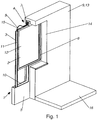
- FIG. 1 to 3 show a preferred embodiment of a hospitalsschiebeppervoriques 1 comprising a window 2 and two guide rails 3, wherein the window 2 is arranged between the two guide rails 3 and along the guide rails 3 is displaceable.
- a building sliding window apparatus 1 is a device having a sliding window 2 for a building 9. For moving the window 2, the building sliding window apparatus 1 has two laterally extending running guide rails 3, the guide rails 3 guiding movement of the window 2 along the guide rails 3.
- an electric drive device 4 for predetermined displacement of the window 2 relative to the Guide rails 3 has.
- An electric drive device 4 is an electrically operated device for predeterminable displacement of the window 2 along the guide rails 3.
- the drive device 4 may in particular have a motor 7, wherein the motor 7 is designed as an electric motor.
- the drive device 4 has means to effect movement of the motor 7, a displacement of the window 2.
- the window 2 of theministerschiebeppervortechnisch 1 can be operated easily and reliably, with a manual handling with the window 2 is omitted.
- the window 2 can be moved into a separate receiving space 10, since it is no longer necessary that the user has to deal directly with the window 2, or handles on the window 2 are necessary.
- the division into two can be omitted, whereby more than half of the window opening 6 can be released.
- the window 2 can give a similarly good sense of space as a casement window, but continue to have a small footprint such as a sliding window.
- the electric drive device 4 improves the safety of the window 2, either by avoiding an accidentally sliding down window 2 and related injuries or by improving the burglary protection.
- the electric drive device 4 allows easy operation by the user, or can be operated without the direct presence of the user, either via the user by means of a remote control or mobile phone, or via a programmable building control. Furthermore, the building sliding window apparatus 1 can be more easily integrated into an alarm system.
- the window 2 may in particular have a window frame 11 and at least one window pane 12. Particularly preferably, the window 2 can have a plurality of window panes 12 arranged one behind the other. Such multiple windows have good thermal insulation.
- thequaintbepperppervoroplasty 1 has only a single window 2.
- the building sliding window apparatus 1 may have a plurality of independently movable windows 2.
- the window 2 is substantially vertically displaceable along the guide rails 3.
- substantially vertical in this context means, in particular, a deviation of up to 15 ° from the vertical in an installed state of the building sliding window device 1. It is advantageous for the essentially vertically displaceable window 2 that a substantially vertically displaceable window 2 with an electric drive device 4 is attached.
- the design of a room has substantially the same space consumption as a conventional casement window, since the space to the side of the window opening 6 is not required for the function of the window as in a side sliding window 2.
- the electric drive device 4 is particularly advantageous because a vertical displacement of the window 2 by the electric drive device 4 is substantially simplified and also a one-piece window 2 can be completely moved.
- Fig. 1 to 3 is a preferred embodiment with a vertically displaceable window 2 shown.
- the window 2 along the guide rails 3 is substantially laterally displaceable.
- the drive device 4 has a control unit, wherein the control unit controls the motor 7, and connected thereto, the position of the window 2.
- the control unit may in particular have an operating unit, a radio unit and / or an electrical communication interface.
- the user can control the drive device 4 directly, the Operating unit in particular may have control elements such as switches or buttons.
- the drive device 4 can be controlled by radio, in particular via a remote control or indirectly via mobile, in particular, the control can be done via a mobile phone by means of an app.
- the drive device 4 can communicate with other electrical systems of the building, in particular with a building control, which also controls other functionalities of the building such as heating and the like, and / or with an alarm system, the alarm system can query a status of Governmentschiebeppervorraum 1.
- the window 2 can be moved between a first position and a second position, wherein in the first position of the window 2 in a position advancing the window opening 6 and the second position represents the position of the window 2 at maximum opening ,
- the window 2 can assume a third position arranged between the first position and the second position, wherein the third position represents in particular a ventilation position.
- the third position can be shifted from the first position by 10 cm to 20 cm, in particular shifted downwards.
- Fig. 1 is the window 2 of the preferred embodiment in the first position, in Fig. 2 in the third position and in Fig. 3 shown in the second position.
- the first position, the second position and the third position of the window 2 in the drive device 4, in particular the control unit of the drive device 4, are stored. This allows the user to quickly and easily switch between these three positions.
- the drive device 4 can position the window continuously between the first position and the second position.
- a building 9 comprising the building slab window device 1 is provided.
- a building 9 comprising the building slab window device 1 is provided.
- Fig. 1 and 3 is of the building 9 only part of a Outside wall 13 and a bottom 16 shown.
- the building sliding window device 1 has a window opening 6 which can be closed by the window 2.
- the window 2, the guide rails 3 and the electric drive device 4 are arranged in a housing 5, wherein the housing 5 has a closable by the window 2 window opening 6.
- the housing 5 can form a substantially closed shell, with the window opening 6 forming a double-sided opening of the housing 5 which can be closed by the window 2.
- the building sliding window device 1 substantially forms a plate in the case of a closed window 2.
- the building sliding window apparatus 1 can be simply used as a substantially complete module in a building 9, and / or a subsequent application of external heat insulation to a building 9.
- the window opening 6 has a, in particular circumferential, seal for the window 2 on at least one side.
- the seal may in particular be arranged on an outwardly directed side of the window opening 6.
- the housing 5 encloses a receiving space 10 for the window 2, wherein in particular the window in the maximum open position, ie the second position, can be arranged substantially completely in the receiving space 10.
- the enclosed receiving space 10 can be prevented that the window 2 when opening objects in the room overturns or injures someone.
- the receiving space 10 is arranged below the window opening 6, wherein the window 2 is moved downwards when opening.
- the window opening 6 has substantially the size of the window 2. As a result, the window opening 6 substantially be completely released from the window 2.
- the Theplayerschiebepperpiecepiecevorutter 1 can be arranged in particular in an outer wall 13 of the building 9.
- the outer wall 13 may have an opening 14 that is substantially aligned with the window opening 6.
- a building sliding window apparatus 1 arranged in the outer wall 13 is illustrative in the preferred embodiment in FIGS Fig. 1 to 3 shown. Here, parts of the outer wall 13 and parts of the housing 5 are cut away to expose the view of the interior ofschreibschiebemultivorraum 1.
- thequaintschieberomevortechnische is arranged at a building 9 in a, in particular subsequently applied, outer wall insulation.
- thereheatschiebebaluze 1 is simply attached to an outer side of the outer wall 13, whereby a thermal insulation even with the windows 2 of a building 9 quickly and can be easily done.
- the housing 5 is thermally insulated.
- the housing 5 inside a layer of a thermal insulation material.
- the window 2 also has conventional thermal insulation measures, for example a multiple glass, the entire building sliding window device 1 can thus be formed as part of the thermal insulation of the building 9, and additional heat insulation in the area around the receiving space 10 can be dispensed with.
- the electric drive device 4 has a motor 7 and a tension element 8, that the window 2 is at least indirectly attached to the tension element 8, and that the motor 7 is at least indirectly positively connected to the tension element 8 in connection to the tension element 8 to move.
- the tension element 8 transmits the movement of the motor 7 to the position of the window 2. Since the tension element 8 is at least indirectly positively connected to the engine 7, in particular via a transmission, and is also attached at least indirectly to the window 2, the window 2 is moved positively via the tension element 8. This allows the drive device 4 to determine the position of the window 2 accurately.
- the transmission may be self-locking, so that the transmission counteracts a displacement of the window 2 with the motor 7 off.
- the drive device 4 is formed hydraulically.
- the drive device 4 has a plurality of motors 7, in particular in each case one motor 7 per guide rail 3. Furthermore, it can be provided that each motor 7 moves a respective tension element 8.
- the tension element 8 can in particular at least partially move along the guide rails 3.
- tension element 8 is flexible, and in particular guided in a sleeve. Due to the flexible tension element 8, the force of the motor 7 can be deflected, whereby a compact design is possible.
- the tension member 8 can be both train and loaded on pressure, such as a Bowden cable, whereby the window 2 is reliably fixed in position by the tension member 8 in both directions.
- the motor is arranged in the region of an upper side of the housing 5, in particular above the window opening 6.
- the tension element 8 remains under tension.
- the drive device 4 can thereby be protected from penetrating into the receiving space 10 moisture.
- the flexible tension element 8 may in particular be a laterally toothed cable, a chain or a toothed belt.
- the tension element has two ends, wherein the window 2 is indirectly attached to a first end.
- a counterweight may be arranged at a second end opposite the first end.
- the transmission of the motor 7 can in particular in a range between the two ends with the tension element 8 in positive connection and move it so.
- the window 2 has an anti-fall device 15 designed as a cross member on an upper side.
- a fall protection device 15 is a device that prevents a person from falling out of an open window opening 6, in particular when the window opening 6 extends substantially to the floor. Such fall protection 15 is particularly necessary when a lower edge of the window opening 6 is disposed below a required minimum height compared to the bottom 16 in the built-in state ofschreibschiebe multvorraum 1.
- the arrangement of the fall protection 15 directly on the top of the window 2 can be dispensed with an additional railing.
- the upper window frame 11 may form the fall protection 15, in particular by a continuous cross member, which is integrated in the window frame 11.
- the second position of the window which corresponds to the maximum open position, in particular when installing themusicschiebeppervorraum 1, be set such that the top of the window 2 is at the height of the legally prescribed minimum height of the fall protection 15, in particular by attachment of a mechanical Barrier in the region of the guide rails 3.
- This can be easily realized a reaching to the bottom window opening 6, it being ensured that the window 2 can only be moved down to a minimum height, and the top of the window 2 mechanically stable enough to to hold back a person.
- the window 2 is connected to the guide rails 3 via a closure device, and that the closure device moves the window 2 transversely to a longitudinal direction of the guide rails 3 between a release position and a closure position.
- the closure device is formed, the window 2 can be predetermined transversely to the longitudinal direction of the guide rails 3 between the Release position and the closed position to move.
- the window 2 can be predetermined transversely to the longitudinal direction of the guide rails 3, that is normal or oblique to this longitudinal direction, moved.
- the window 2 is pressed in the closed position by the closure device against a seal of the window opening 6, whereby the window 2 in the first position, the window opening 6 closes tightly, and that for moving the window 2, the window 2 through the Locking device is lifted from the seal, whereby the window 2 can be moved in the release position without damaging the seal. Furthermore, it can be provided that the window 2 is pressed in the closed position by the closure device against the seal of the window opening 6, and that the window 2 is lifted in the release position for moving the window 2 by the closure device of the seal.
- the window is pressed in a position other than the first position in the closed position, at least against a, preferably lowermost, seal of the window opening 6. Thereby, a penetration of rainwater into the receiving space 10 can be prevented.
- the closure device may in particular have a plurality of closure mechanisms which each connect the window 2 to one of the guide rails 3, so that the window 2 is connected to the guide rails 3 only via the closure mechanisms.
- at least two locking mechanisms can be provided per guide rail 3. Thereby, the window 2 can be moved along with the locking mechanisms in the longitudinal direction of the guide rail 3, wherein the locking mechanisms allow additional movement of the window 2 transversely to the longitudinal direction of the guide rails 3, whereby a decoupling of these two movements is achieved.
- the tension element 8 can in particular act on at least one of the closure mechanisms.
- the closure mechanisms may in particular have their own motor. Furthermore, it is provided that in the region of the guide rails 3 a plurality of detents are arranged, and that on the window 2, in particular on the window frame 11, projections are arranged, wherein the projections are arranged in the closed position in at least one detent, and disengaged in the release position are the rest.
- the notches may in particular be arranged such that the projections of the window are arranged in the first position in detents.
- further notches, in particular for the second position and / or the third position of the window 2 may be arranged.
- a locking device can be provided with extendable locking bolt, which locking bolts are movably disposed in the window 2 and / or the closure device, wherein the locking bolts extend in a locking position and engage in openings to lock the position of the window.
- the locking device may be configured to lock the window 2 in the first position.
- thequaintschiebepperpper 1 comprises a releasably attachable cleaning device that the cleaning device is fixed in a cleaning position fixed to the guide rails 3 and cleans the window 2 in a relative movement between the window 2 and the guide rails 3.
- windows 2, in particular the window pane 12 can be easily guided past the cleaning device by moving the window from the first position into the second position or vice versa, and thereby be cleaned.
- the cleaning device may in particular have a length which corresponds to the width of the window 2.
- the cleaning device may in particular have a cleaning side facing the window 2, wherein a brush, a sponge and / or a discharge lip is provided on the cleaning side.
- fastening receptacles for the cleaning device are arranged.
- the fastening receptacles are arranged both on the outwardly directed side of the window opening 6 and the inwardly directed side of the window opening 6.
- the cleaning device can clean both an outer side and an inner side of the window 2.
Landscapes
- Engineering & Computer Science (AREA)
- Civil Engineering (AREA)
- Structural Engineering (AREA)
- Mechanical Engineering (AREA)
- Power-Operated Mechanisms For Wings (AREA)
Applications Claiming Priority (1)
| Application Number | Priority Date | Filing Date | Title |
|---|---|---|---|
| ATA50398/2016A AT518407B1 (de) | 2016-05-02 | 2016-05-02 | Gebäudeschiebefenstervorrichtung |
Publications (2)
| Publication Number | Publication Date |
|---|---|
| EP3241971A1 true EP3241971A1 (fr) | 2017-11-08 |
| EP3241971B1 EP3241971B1 (fr) | 2020-06-10 |
Family
ID=58638748
Family Applications (1)
| Application Number | Title | Priority Date | Filing Date |
|---|---|---|---|
| EP17168360.0A Active EP3241971B1 (fr) | 2016-05-02 | 2017-04-27 | Dispositif de fenêtre coulissante de bâtiment |
Country Status (3)
| Country | Link |
|---|---|
| EP (1) | EP3241971B1 (fr) |
| AT (1) | AT518407B1 (fr) |
| MA (1) | MA45278A (fr) |
Cited By (1)
| Publication number | Priority date | Publication date | Assignee | Title |
|---|---|---|---|---|
| EP3783267A1 (fr) * | 2019-08-21 | 2021-02-24 | Yu-Shu Chen | Appareil de guidage et de protection contre la fumée de cuisson extensible et rétractable |
Citations (3)
| Publication number | Priority date | Publication date | Assignee | Title |
|---|---|---|---|---|
| US1935559A (en) * | 1930-02-04 | 1933-11-14 | Herman Alexander | Sliding window |
| GB726734A (en) * | 1953-05-11 | 1955-03-23 | Nils Folke Ragnar Hederus | Improvements in sash-windows |
| DE2059505A1 (de) * | 1970-12-03 | 1972-08-10 | Krupp Gmbh | Fenster mit eingebauter Reinigungsvorrichtung |
Family Cites Families (3)
| Publication number | Priority date | Publication date | Assignee | Title |
|---|---|---|---|---|
| ATE214775T1 (de) * | 1996-12-31 | 2002-04-15 | Hirt Metallbau Ag | Vertikalschiebefenster |
| US20030024167A1 (en) * | 2001-08-01 | 2003-02-06 | Cheng Chao Hsing | Central control for windows |
| ITPI20100042A1 (it) * | 2010-03-31 | 2011-10-01 | Frangerini S R L | Struttura di finestra |
-
2016
- 2016-05-02 AT ATA50398/2016A patent/AT518407B1/de active
-
2017
- 2017-04-27 EP EP17168360.0A patent/EP3241971B1/fr active Active
- 2017-04-27 MA MA045278A patent/MA45278A/fr unknown
Patent Citations (3)
| Publication number | Priority date | Publication date | Assignee | Title |
|---|---|---|---|---|
| US1935559A (en) * | 1930-02-04 | 1933-11-14 | Herman Alexander | Sliding window |
| GB726734A (en) * | 1953-05-11 | 1955-03-23 | Nils Folke Ragnar Hederus | Improvements in sash-windows |
| DE2059505A1 (de) * | 1970-12-03 | 1972-08-10 | Krupp Gmbh | Fenster mit eingebauter Reinigungsvorrichtung |
Cited By (1)
| Publication number | Priority date | Publication date | Assignee | Title |
|---|---|---|---|---|
| EP3783267A1 (fr) * | 2019-08-21 | 2021-02-24 | Yu-Shu Chen | Appareil de guidage et de protection contre la fumée de cuisson extensible et rétractable |
Also Published As
| Publication number | Publication date |
|---|---|
| EP3241971B1 (fr) | 2020-06-10 |
| AT518407A4 (de) | 2017-10-15 |
| MA45278A (fr) | 2017-11-08 |
| AT518407B1 (de) | 2017-10-15 |
Similar Documents
| Publication | Publication Date | Title |
|---|---|---|
| EP2103771B2 (fr) | Porte | |
| DE10216983A1 (de) | Schiebetüranlage | |
| EP2840223B1 (fr) | Volet roulant, rideau pare-feu et volet roulant coupe-feu | |
| EP2626491B1 (fr) | Agencement de ferrure | |
| EP3658734B1 (fr) | Système de porte | |
| EP3361029B1 (fr) | Dispositif d'entraînement pour un battant de porte ou de fenêtre | |
| AT518407B1 (de) | Gebäudeschiebefenstervorrichtung | |
| EP1449994B1 (fr) | Fenêtre, porte ou analogue avec une unité d'entraínement motorisée pour crémone-serrure | |
| EP0853713B1 (fr) | Glissiere | |
| DE19531040C2 (de) | Schiebeladen für ein Fenster- oder Türelement | |
| EP3526432B1 (fr) | Élément coulissant | |
| DE10160802A1 (de) | Automatische Schiebetüranlage mit Seitenprofil | |
| DE19900875C2 (de) | Verriegelungsvorrichtung für eine Türanlage | |
| EP3702555A1 (fr) | Agencement de porte ou de fenêtre doté d'une unité d'entraînement dans le bâti dormant | |
| DE3001231A1 (de) | Auflaufsicherung fuer rolltore | |
| EP3483374B1 (fr) | Rail de guidage permettant le guidage d'un battant de porte entre une position d'ouverture et une position de fermeture | |
| EP1405974B1 (fr) | Mécanisme de verrouillage pour fenêtre ou porte oscillobattante | |
| EP0916795B1 (fr) | Dispositif de sécurité pour les endroits à risques d'écrasement et de coupe d'un vantail pivotant motorisé, vantail de fenêtre, porte ou similaire | |
| EP4474610B1 (fr) | Dispositif de protection pour une ouverture de bâtiment et ouverture de bâtiment dotée d'un tel dispositif de protection | |
| EP2851501A1 (fr) | Porte sectionnelle | |
| EP4421285B1 (fr) | Porte coulissante avec un battant coulissant verrouillable | |
| EP3415706A1 (fr) | Porte | |
| EP2699749A2 (fr) | Verrouillage de profilé de socle pour l'axe x et l'axe y d'un portail par sections ou d'un portail accordéon relevable par sections, équipé d'un dispositif d'arrêt de bord de fermeture et d'une porte d'issue de secours sans seuil à déclenchement libre | |
| EP4474611A1 (fr) | Ouverture de bâtiment dotée d'un dispositif de protection | |
| EP3460158B1 (fr) | Rail de guidage permettant le guidage d'un battant de porte entre une position d'ouverture ou une position de fermeture d'une ouverture pour porte dans un mur |
Legal Events
| Date | Code | Title | Description |
|---|---|---|---|
| PUAI | Public reference made under article 153(3) epc to a published international application that has entered the european phase |
Free format text: ORIGINAL CODE: 0009012 |
|
| STAA | Information on the status of an ep patent application or granted ep patent |
Free format text: STATUS: THE APPLICATION HAS BEEN PUBLISHED |
|
| AK | Designated contracting states |
Kind code of ref document: A1 Designated state(s): AL AT BE BG CH CY CZ DE DK EE ES FI FR GB GR HR HU IE IS IT LI LT LU LV MC MK MT NL NO PL PT RO RS SE SI SK SM TR |
|
| AX | Request for extension of the european patent |
Extension state: BA ME |
|
| STAA | Information on the status of an ep patent application or granted ep patent |
Free format text: STATUS: REQUEST FOR EXAMINATION WAS MADE |
|
| 17P | Request for examination filed |
Effective date: 20180508 |
|
| RAV | Requested validation state of the european patent: fee paid |
Extension state: MA Effective date: 20180508 Extension state: MD Effective date: 20180508 |
|
| RAX | Requested extension states of the european patent have changed |
Extension state: BA Payment date: 20180508 Extension state: ME Payment date: 20180508 |
|
| RBV | Designated contracting states (corrected) |
Designated state(s): AL AT BE BG CH CY CZ DE DK EE ES FI FR GB GR HR HU IE IS IT LI LT LU LV MC MK MT NL NO PL PT RO RS SE SI SK SM TR |
|
| STAA | Information on the status of an ep patent application or granted ep patent |
Free format text: STATUS: EXAMINATION IS IN PROGRESS |
|
| 17Q | First examination report despatched |
Effective date: 20181210 |
|
| GRAP | Despatch of communication of intention to grant a patent |
Free format text: ORIGINAL CODE: EPIDOSNIGR1 |
|
| STAA | Information on the status of an ep patent application or granted ep patent |
Free format text: STATUS: GRANT OF PATENT IS INTENDED |
|
| INTG | Intention to grant announced |
Effective date: 20200110 |
|
| GRAS | Grant fee paid |
Free format text: ORIGINAL CODE: EPIDOSNIGR3 |
|
| GRAA | (expected) grant |
Free format text: ORIGINAL CODE: 0009210 |
|
| STAA | Information on the status of an ep patent application or granted ep patent |
Free format text: STATUS: THE PATENT HAS BEEN GRANTED |
|
| AK | Designated contracting states |
Kind code of ref document: B1 Designated state(s): AL AT BE BG CH CY CZ DE DK EE ES FI FR GB GR HR HU IE IS IT LI LT LU LV MC MK MT NL NO PL PT RO RS SE SI SK SM TR |
|
| AX | Request for extension of the european patent |
Extension state: BA ME |
|
| REG | Reference to a national code |
Ref country code: GB Ref legal event code: FG4D Free format text: NOT ENGLISH |
|
| REG | Reference to a national code |
Ref country code: CH Ref legal event code: EP Ref country code: AT Ref legal event code: REF Ref document number: 1279329 Country of ref document: AT Kind code of ref document: T Effective date: 20200615 |
|
| REG | Reference to a national code |
Ref country code: DE Ref legal event code: R096 Ref document number: 502017005623 Country of ref document: DE |
|
| REG | Reference to a national code |
Ref country code: IE Ref legal event code: FG4D Free format text: LANGUAGE OF EP DOCUMENT: GERMAN |
|
| REG | Reference to a national code |
Ref country code: LT Ref legal event code: MG4D |
|
| PG25 | Lapsed in a contracting state [announced via postgrant information from national office to epo] |
Ref country code: LT Free format text: LAPSE BECAUSE OF FAILURE TO SUBMIT A TRANSLATION OF THE DESCRIPTION OR TO PAY THE FEE WITHIN THE PRESCRIBED TIME-LIMIT Effective date: 20200610 Ref country code: FI Free format text: LAPSE BECAUSE OF FAILURE TO SUBMIT A TRANSLATION OF THE DESCRIPTION OR TO PAY THE FEE WITHIN THE PRESCRIBED TIME-LIMIT Effective date: 20200610 Ref country code: GR Free format text: LAPSE BECAUSE OF FAILURE TO SUBMIT A TRANSLATION OF THE DESCRIPTION OR TO PAY THE FEE WITHIN THE PRESCRIBED TIME-LIMIT Effective date: 20200911 Ref country code: NO Free format text: LAPSE BECAUSE OF FAILURE TO SUBMIT A TRANSLATION OF THE DESCRIPTION OR TO PAY THE FEE WITHIN THE PRESCRIBED TIME-LIMIT Effective date: 20200910 Ref country code: SE Free format text: LAPSE BECAUSE OF FAILURE TO SUBMIT A TRANSLATION OF THE DESCRIPTION OR TO PAY THE FEE WITHIN THE PRESCRIBED TIME-LIMIT Effective date: 20200610 |
|
| REG | Reference to a national code |
Ref country code: NL Ref legal event code: MP Effective date: 20200610 |
|
| PG25 | Lapsed in a contracting state [announced via postgrant information from national office to epo] |
Ref country code: LV Free format text: LAPSE BECAUSE OF FAILURE TO SUBMIT A TRANSLATION OF THE DESCRIPTION OR TO PAY THE FEE WITHIN THE PRESCRIBED TIME-LIMIT Effective date: 20200610 Ref country code: BG Free format text: LAPSE BECAUSE OF FAILURE TO SUBMIT A TRANSLATION OF THE DESCRIPTION OR TO PAY THE FEE WITHIN THE PRESCRIBED TIME-LIMIT Effective date: 20200910 Ref country code: HR Free format text: LAPSE BECAUSE OF FAILURE TO SUBMIT A TRANSLATION OF THE DESCRIPTION OR TO PAY THE FEE WITHIN THE PRESCRIBED TIME-LIMIT Effective date: 20200610 Ref country code: RS Free format text: LAPSE BECAUSE OF FAILURE TO SUBMIT A TRANSLATION OF THE DESCRIPTION OR TO PAY THE FEE WITHIN THE PRESCRIBED TIME-LIMIT Effective date: 20200610 |
|
| PG25 | Lapsed in a contracting state [announced via postgrant information from national office to epo] |
Ref country code: AL Free format text: LAPSE BECAUSE OF FAILURE TO SUBMIT A TRANSLATION OF THE DESCRIPTION OR TO PAY THE FEE WITHIN THE PRESCRIBED TIME-LIMIT Effective date: 20200610 Ref country code: NL Free format text: LAPSE BECAUSE OF FAILURE TO SUBMIT A TRANSLATION OF THE DESCRIPTION OR TO PAY THE FEE WITHIN THE PRESCRIBED TIME-LIMIT Effective date: 20200610 |
|
| PG25 | Lapsed in a contracting state [announced via postgrant information from national office to epo] |
Ref country code: IT Free format text: LAPSE BECAUSE OF FAILURE TO SUBMIT A TRANSLATION OF THE DESCRIPTION OR TO PAY THE FEE WITHIN THE PRESCRIBED TIME-LIMIT Effective date: 20200610 Ref country code: RO Free format text: LAPSE BECAUSE OF FAILURE TO SUBMIT A TRANSLATION OF THE DESCRIPTION OR TO PAY THE FEE WITHIN THE PRESCRIBED TIME-LIMIT Effective date: 20200610 Ref country code: PT Free format text: LAPSE BECAUSE OF FAILURE TO SUBMIT A TRANSLATION OF THE DESCRIPTION OR TO PAY THE FEE WITHIN THE PRESCRIBED TIME-LIMIT Effective date: 20201012 Ref country code: ES Free format text: LAPSE BECAUSE OF FAILURE TO SUBMIT A TRANSLATION OF THE DESCRIPTION OR TO PAY THE FEE WITHIN THE PRESCRIBED TIME-LIMIT Effective date: 20200610 Ref country code: CZ Free format text: LAPSE BECAUSE OF FAILURE TO SUBMIT A TRANSLATION OF THE DESCRIPTION OR TO PAY THE FEE WITHIN THE PRESCRIBED TIME-LIMIT Effective date: 20200610 Ref country code: SM Free format text: LAPSE BECAUSE OF FAILURE TO SUBMIT A TRANSLATION OF THE DESCRIPTION OR TO PAY THE FEE WITHIN THE PRESCRIBED TIME-LIMIT Effective date: 20200610 Ref country code: EE Free format text: LAPSE BECAUSE OF FAILURE TO SUBMIT A TRANSLATION OF THE DESCRIPTION OR TO PAY THE FEE WITHIN THE PRESCRIBED TIME-LIMIT Effective date: 20200610 |
|
| PG25 | Lapsed in a contracting state [announced via postgrant information from national office to epo] |
Ref country code: SK Free format text: LAPSE BECAUSE OF FAILURE TO SUBMIT A TRANSLATION OF THE DESCRIPTION OR TO PAY THE FEE WITHIN THE PRESCRIBED TIME-LIMIT Effective date: 20200610 Ref country code: PL Free format text: LAPSE BECAUSE OF FAILURE TO SUBMIT A TRANSLATION OF THE DESCRIPTION OR TO PAY THE FEE WITHIN THE PRESCRIBED TIME-LIMIT Effective date: 20200610 Ref country code: IS Free format text: LAPSE BECAUSE OF FAILURE TO SUBMIT A TRANSLATION OF THE DESCRIPTION OR TO PAY THE FEE WITHIN THE PRESCRIBED TIME-LIMIT Effective date: 20201010 |
|
| VS25 | Lapsed in a validation state [announced via postgrant information from nat. office to epo] |
Ref country code: MD Free format text: LAPSE BECAUSE OF FAILURE TO SUBMIT A TRANSLATION OF THE DESCRIPTION OR TO PAY THE FEE WITHIN THE PRESCRIBED TIME-LIMIT Effective date: 20200610 |
|
| REG | Reference to a national code |
Ref country code: DE Ref legal event code: R097 Ref document number: 502017005623 Country of ref document: DE |
|
| PLBE | No opposition filed within time limit |
Free format text: ORIGINAL CODE: 0009261 |
|
| STAA | Information on the status of an ep patent application or granted ep patent |
Free format text: STATUS: NO OPPOSITION FILED WITHIN TIME LIMIT |
|
| PG25 | Lapsed in a contracting state [announced via postgrant information from national office to epo] |
Ref country code: DK Free format text: LAPSE BECAUSE OF FAILURE TO SUBMIT A TRANSLATION OF THE DESCRIPTION OR TO PAY THE FEE WITHIN THE PRESCRIBED TIME-LIMIT Effective date: 20200610 |
|
| 26N | No opposition filed |
Effective date: 20210311 |
|
| PG25 | Lapsed in a contracting state [announced via postgrant information from national office to epo] |
Ref country code: SI Free format text: LAPSE BECAUSE OF FAILURE TO SUBMIT A TRANSLATION OF THE DESCRIPTION OR TO PAY THE FEE WITHIN THE PRESCRIBED TIME-LIMIT Effective date: 20200610 |
|
| REG | Reference to a national code |
Ref country code: DE Ref legal event code: R119 Ref document number: 502017005623 Country of ref document: DE |
|
| PG25 | Lapsed in a contracting state [announced via postgrant information from national office to epo] |
Ref country code: MC Free format text: LAPSE BECAUSE OF FAILURE TO SUBMIT A TRANSLATION OF THE DESCRIPTION OR TO PAY THE FEE WITHIN THE PRESCRIBED TIME-LIMIT Effective date: 20200610 |
|
| GBPC | Gb: european patent ceased through non-payment of renewal fee |
Effective date: 20210427 |
|
| PG25 | Lapsed in a contracting state [announced via postgrant information from national office to epo] |
Ref country code: LU Free format text: LAPSE BECAUSE OF NON-PAYMENT OF DUE FEES Effective date: 20210427 |
|
| REG | Reference to a national code |
Ref country code: BE Ref legal event code: MM Effective date: 20210430 |
|
| PG25 | Lapsed in a contracting state [announced via postgrant information from national office to epo] |
Ref country code: DE Free format text: LAPSE BECAUSE OF NON-PAYMENT OF DUE FEES Effective date: 20211103 Ref country code: CH Free format text: LAPSE BECAUSE OF NON-PAYMENT OF DUE FEES Effective date: 20210430 Ref country code: LI Free format text: LAPSE BECAUSE OF NON-PAYMENT OF DUE FEES Effective date: 20210430 Ref country code: GB Free format text: LAPSE BECAUSE OF NON-PAYMENT OF DUE FEES Effective date: 20210427 Ref country code: FR Free format text: LAPSE BECAUSE OF NON-PAYMENT OF DUE FEES Effective date: 20210430 |
|
| PG25 | Lapsed in a contracting state [announced via postgrant information from national office to epo] |
Ref country code: IE Free format text: LAPSE BECAUSE OF NON-PAYMENT OF DUE FEES Effective date: 20210427 |
|
| PG25 | Lapsed in a contracting state [announced via postgrant information from national office to epo] |
Ref country code: IS Free format text: LAPSE BECAUSE OF FAILURE TO SUBMIT A TRANSLATION OF THE DESCRIPTION OR TO PAY THE FEE WITHIN THE PRESCRIBED TIME-LIMIT Effective date: 20201010 |
|
| PG25 | Lapsed in a contracting state [announced via postgrant information from national office to epo] |
Ref country code: BE Free format text: LAPSE BECAUSE OF NON-PAYMENT OF DUE FEES Effective date: 20210430 |
|
| PG25 | Lapsed in a contracting state [announced via postgrant information from national office to epo] |
Ref country code: HU Free format text: LAPSE BECAUSE OF FAILURE TO SUBMIT A TRANSLATION OF THE DESCRIPTION OR TO PAY THE FEE WITHIN THE PRESCRIBED TIME-LIMIT; INVALID AB INITIO Effective date: 20170427 |
|
| REG | Reference to a national code |
Ref country code: AT Ref legal event code: MM01 Ref document number: 1279329 Country of ref document: AT Kind code of ref document: T Effective date: 20220427 |
|
| PG25 | Lapsed in a contracting state [announced via postgrant information from national office to epo] |
Ref country code: CY Free format text: LAPSE BECAUSE OF FAILURE TO SUBMIT A TRANSLATION OF THE DESCRIPTION OR TO PAY THE FEE WITHIN THE PRESCRIBED TIME-LIMIT Effective date: 20200610 |
|
| PG25 | Lapsed in a contracting state [announced via postgrant information from national office to epo] |
Ref country code: AT Free format text: LAPSE BECAUSE OF NON-PAYMENT OF DUE FEES Effective date: 20220427 |
|
| PG25 | Lapsed in a contracting state [announced via postgrant information from national office to epo] |
Ref country code: MK Free format text: LAPSE BECAUSE OF FAILURE TO SUBMIT A TRANSLATION OF THE DESCRIPTION OR TO PAY THE FEE WITHIN THE PRESCRIBED TIME-LIMIT Effective date: 20200610 |
|
| VS25 | Lapsed in a validation state [announced via postgrant information from nat. office to epo] |
Ref country code: MA Free format text: LAPSE BECAUSE OF FAILURE TO SUBMIT A TRANSLATION OF THE DESCRIPTION OR TO PAY THE FEE WITHIN THE PRESCRIBED TIME-LIMIT Effective date: 20200610 |
|
| PG25 | Lapsed in a contracting state [announced via postgrant information from national office to epo] |
Ref country code: TR Free format text: LAPSE BECAUSE OF FAILURE TO SUBMIT A TRANSLATION OF THE DESCRIPTION OR TO PAY THE FEE WITHIN THE PRESCRIBED TIME-LIMIT Effective date: 20200610 |
|
| PG25 | Lapsed in a contracting state [announced via postgrant information from national office to epo] |
Ref country code: MT Free format text: LAPSE BECAUSE OF FAILURE TO SUBMIT A TRANSLATION OF THE DESCRIPTION OR TO PAY THE FEE WITHIN THE PRESCRIBED TIME-LIMIT Effective date: 20200610 |