EP3241978A1 - Mehrteiliger griff - Google Patents
Mehrteiliger griff Download PDFInfo
- Publication number
- EP3241978A1 EP3241978A1 EP17168981.3A EP17168981A EP3241978A1 EP 3241978 A1 EP3241978 A1 EP 3241978A1 EP 17168981 A EP17168981 A EP 17168981A EP 3241978 A1 EP3241978 A1 EP 3241978A1
- Authority
- EP
- European Patent Office
- Prior art keywords
- degradable
- component
- grip
- particles
- alloy
- Prior art date
- Legal status (The legal status is an assumption and is not a legal conclusion. Google has not performed a legal analysis and makes no representation as to the accuracy of the status listed.)
- Granted
Links
Images










Classifications
-
- B—PERFORMING OPERATIONS; TRANSPORTING
- B22—CASTING; POWDER METALLURGY
- B22F—WORKING METALLIC POWDER; MANUFACTURE OF ARTICLES FROM METALLIC POWDER; MAKING METALLIC POWDER; APPARATUS OR DEVICES SPECIALLY ADAPTED FOR METALLIC POWDER
- B22F3/00—Manufacture of workpieces or articles from metallic powder characterised by the manner of compacting or sintering; Apparatus specially adapted therefor ; Presses and furnaces
- B22F3/02—Compacting only
-
- B—PERFORMING OPERATIONS; TRANSPORTING
- B22—CASTING; POWDER METALLURGY
- B22F—WORKING METALLIC POWDER; MANUFACTURE OF ARTICLES FROM METALLIC POWDER; MAKING METALLIC POWDER; APPARATUS OR DEVICES SPECIALLY ADAPTED FOR METALLIC POWDER
- B22F7/00—Manufacture of composite layers, workpieces, or articles, comprising metallic powder, by sintering the powder, with or without compacting wherein at least one part is obtained by sintering or compression
- B22F7/008—Manufacture of composite layers, workpieces, or articles, comprising metallic powder, by sintering the powder, with or without compacting wherein at least one part is obtained by sintering or compression characterised by the composition
-
- B—PERFORMING OPERATIONS; TRANSPORTING
- B28—WORKING CEMENT, CLAY, OR STONE
- B28B—SHAPING CLAY OR OTHER CERAMIC COMPOSITIONS; SHAPING SLAG; SHAPING MIXTURES CONTAINING CEMENTITIOUS MATERIAL, e.g. PLASTER
- B28B3/00—Producing shaped articles from the material by using presses; Presses specially adapted therefor
- B28B3/02—Producing shaped articles from the material by using presses; Presses specially adapted therefor wherein a ram exerts pressure on the material in a moulding space; Ram heads of special form
-
- C—CHEMISTRY; METALLURGY
- C22—METALLURGY; FERROUS OR NON-FERROUS ALLOYS; TREATMENT OF ALLOYS OR NON-FERROUS METALS
- C22C—ALLOYS
- C22C26/00—Alloys containing diamond or cubic or wurtzitic boron nitride, fullerenes or carbon nanotubes
-
- C—CHEMISTRY; METALLURGY
- C22—METALLURGY; FERROUS OR NON-FERROUS ALLOYS; TREATMENT OF ALLOYS OR NON-FERROUS METALS
- C22C—ALLOYS
- C22C29/00—Alloys based on carbides, oxides, nitrides, borides, or silicides, e.g. cermets, or other metal compounds, e.g. oxynitrides, sulfides
- C22C29/02—Alloys based on carbides, oxides, nitrides, borides, or silicides, e.g. cermets, or other metal compounds, e.g. oxynitrides, sulfides based on carbides or carbonitrides
- C22C29/06—Alloys based on carbides, oxides, nitrides, borides, or silicides, e.g. cermets, or other metal compounds, e.g. oxynitrides, sulfides based on carbides or carbonitrides based on carbides, but not containing other metal compounds
- C22C29/067—Alloys based on carbides, oxides, nitrides, borides, or silicides, e.g. cermets, or other metal compounds, e.g. oxynitrides, sulfides based on carbides or carbonitrides based on carbides, but not containing other metal compounds comprising a particular metallic binder
-
- E—FIXED CONSTRUCTIONS
- E21—EARTH OR ROCK DRILLING; MINING
- E21B—EARTH OR ROCK DRILLING; OBTAINING OIL, GAS, WATER, SOLUBLE OR MELTABLE MATERIALS OR A SLURRY OF MINERALS FROM WELLS
- E21B23/00—Apparatus for displacing, setting, locking, releasing or removing tools, packers or the like in boreholes or wells
-
- E—FIXED CONSTRUCTIONS
- E21—EARTH OR ROCK DRILLING; MINING
- E21B—EARTH OR ROCK DRILLING; OBTAINING OIL, GAS, WATER, SOLUBLE OR MELTABLE MATERIALS OR A SLURRY OF MINERALS FROM WELLS
- E21B23/00—Apparatus for displacing, setting, locking, releasing or removing tools, packers or the like in boreholes or wells
- E21B23/01—Apparatus for displacing, setting, locking, releasing or removing tools, packers or the like in boreholes or wells for anchoring the tools or the like
-
- E—FIXED CONSTRUCTIONS
- E21—EARTH OR ROCK DRILLING; MINING
- E21B—EARTH OR ROCK DRILLING; OBTAINING OIL, GAS, WATER, SOLUBLE OR MELTABLE MATERIALS OR A SLURRY OF MINERALS FROM WELLS
- E21B33/00—Sealing or packing boreholes or wells
- E21B33/10—Sealing or packing boreholes or wells in the borehole
- E21B33/12—Packers; Plugs
-
- B—PERFORMING OPERATIONS; TRANSPORTING
- B22—CASTING; POWDER METALLURGY
- B22F—WORKING METALLIC POWDER; MANUFACTURE OF ARTICLES FROM METALLIC POWDER; MAKING METALLIC POWDER; APPARATUS OR DEVICES SPECIALLY ADAPTED FOR METALLIC POWDER
- B22F3/00—Manufacture of workpieces or articles from metallic powder characterised by the manner of compacting or sintering; Apparatus specially adapted therefor ; Presses and furnaces
- B22F3/24—After-treatment of workpieces or articles
- B22F2003/241—Chemical after-treatment on the surface
- B22F2003/244—Leaching
-
- B—PERFORMING OPERATIONS; TRANSPORTING
- B22—CASTING; POWDER METALLURGY
- B22F—WORKING METALLIC POWDER; MANUFACTURE OF ARTICLES FROM METALLIC POWDER; MAKING METALLIC POWDER; APPARATUS OR DEVICES SPECIALLY ADAPTED FOR METALLIC POWDER
- B22F5/00—Manufacture of workpieces or articles from metallic powder characterised by the special shape of the product
- B22F2005/001—Cutting tools, earth boring or grinding tool other than table ware
-
- B—PERFORMING OPERATIONS; TRANSPORTING
- B22—CASTING; POWDER METALLURGY
- B22F—WORKING METALLIC POWDER; MANUFACTURE OF ARTICLES FROM METALLIC POWDER; MAKING METALLIC POWDER; APPARATUS OR DEVICES SPECIALLY ADAPTED FOR METALLIC POWDER
- B22F2301/00—Metallic composition of the powder or its coating
- B22F2301/30—Low melting point metals, i.e. Zn, Pb, Sn, Cd, In, Ga
-
- B—PERFORMING OPERATIONS; TRANSPORTING
- B22—CASTING; POWDER METALLURGY
- B22F—WORKING METALLIC POWDER; MANUFACTURE OF ARTICLES FROM METALLIC POWDER; MAKING METALLIC POWDER; APPARATUS OR DEVICES SPECIALLY ADAPTED FOR METALLIC POWDER
- B22F2302/00—Metal Compound, non-Metallic compound or non-metal composition of the powder or its coating
- B22F2302/10—Carbide
-
- B—PERFORMING OPERATIONS; TRANSPORTING
- B22—CASTING; POWDER METALLURGY
- B22F—WORKING METALLIC POWDER; MANUFACTURE OF ARTICLES FROM METALLIC POWDER; MAKING METALLIC POWDER; APPARATUS OR DEVICES SPECIALLY ADAPTED FOR METALLIC POWDER
- B22F2302/00—Metal Compound, non-Metallic compound or non-metal composition of the powder or its coating
- B22F2302/40—Carbon, graphite
- B22F2302/406—Diamond
-
- B—PERFORMING OPERATIONS; TRANSPORTING
- B22—CASTING; POWDER METALLURGY
- B22F—WORKING METALLIC POWDER; MANUFACTURE OF ARTICLES FROM METALLIC POWDER; MAKING METALLIC POWDER; APPARATUS OR DEVICES SPECIALLY ADAPTED FOR METALLIC POWDER
- B22F2998/00—Supplementary information concerning processes or compositions relating to powder metallurgy
- B22F2998/10—Processes characterised by the sequence of their steps
-
- B—PERFORMING OPERATIONS; TRANSPORTING
- B22—CASTING; POWDER METALLURGY
- B22F—WORKING METALLIC POWDER; MANUFACTURE OF ARTICLES FROM METALLIC POWDER; MAKING METALLIC POWDER; APPARATUS OR DEVICES SPECIALLY ADAPTED FOR METALLIC POWDER
- B22F3/00—Manufacture of workpieces or articles from metallic powder characterised by the manner of compacting or sintering; Apparatus specially adapted therefor ; Presses and furnaces
- B22F3/24—After-treatment of workpieces or articles
-
- B—PERFORMING OPERATIONS; TRANSPORTING
- B22—CASTING; POWDER METALLURGY
- B22F—WORKING METALLIC POWDER; MANUFACTURE OF ARTICLES FROM METALLIC POWDER; MAKING METALLIC POWDER; APPARATUS OR DEVICES SPECIALLY ADAPTED FOR METALLIC POWDER
- B22F5/00—Manufacture of workpieces or articles from metallic powder characterised by the special shape of the product
- B22F5/003—Articles made for being fractured or separated into parts
-
- C—CHEMISTRY; METALLURGY
- C22—METALLURGY; FERROUS OR NON-FERROUS ALLOYS; TREATMENT OF ALLOYS OR NON-FERROUS METALS
- C22C—ALLOYS
- C22C26/00—Alloys containing diamond or cubic or wurtzitic boron nitride, fullerenes or carbon nanotubes
- C22C2026/006—Alloys containing diamond or cubic or wurtzitic boron nitride, fullerenes or carbon nanotubes with additional metal compounds being carbides
-
- C—CHEMISTRY; METALLURGY
- C22—METALLURGY; FERROUS OR NON-FERROUS ALLOYS; TREATMENT OF ALLOYS OR NON-FERROUS METALS
- C22C—ALLOYS
- C22C2204/00—End product comprising different layers, coatings or parts of cermet
-
- E—FIXED CONSTRUCTIONS
- E21—EARTH OR ROCK DRILLING; MINING
- E21B—EARTH OR ROCK DRILLING; OBTAINING OIL, GAS, WATER, SOLUBLE OR MELTABLE MATERIALS OR A SLURRY OF MINERALS FROM WELLS
- E21B2200/00—Special features related to earth drilling for obtaining oil, gas or water
- E21B2200/08—Down-hole devices using materials which decompose under well-bore conditions
Definitions
- equipment may be used in one or more of a sensing operation, a drilling operation, a cementing operation, a fracturing operation, a production operation, etc.
- a component can include a degradable portion that is degradable in an aqueous environment; and a non-degradable portion that is not degradable in the aqueous environment where the non-degradable portion can include polycrystalline diamond.
- a method can include pressing materials that include a degradable portion that includes material that is degradable in an aqueous environment and a non-degradable portion that includes material that is not degradable in the aqueous environment; and forming at least one grip from the pressed materials.
- a method may include operating one or more components of a liner hanger system.
- a lower completion may be a portion of a well that is at least in part in a production zone or an injection zone.
- a liner hanger system may be implemented to perform one or more operations associated with a lower completion, for example, including setting one or more components of a lower completion, etc.
- a liner hanger system may anchor one or more components of a lower completion to a production casing string.
- equipment may include one or more plugs, one or more seats that can receive a respective plug, etc.
- a plug and/or a seat may have properties suited for one or more operation or operations. Properties may include mechanical properties and may include one or more other types of properties (e.g., chemical, electrical, etc.).
- a plug and/or a seat degrade.
- a plug and/or a seat may be manufactured with properties such that the plug and/or the seat degrade when exposed to one or more conditions. In such an example, where the plug acts to block a passage, upon degradation, the passage may become unblocked.
- a component may degrade in a manner that facilitates one or more operations.
- a component or a portion of a component may degrade in stages. For example, consider a plug that degrades from a first size to a second smaller size. In such an example, the second smaller size may allow the plug to move (e.g., from a first seat to a second seat, etc.).
- a plug tool may be a degradable tool.
- a plug tool may be degradable in part. For example, consider a plug tool with a degradable seat or degradable seats.
- a plug may be seated in a degradable seat that upon degradation of the seat, the plug may pass through the seat (e.g., become unplugged with respect to that seat).
- a system can include a plug tool that is degradable at least in part and can also include one or more degradable plugs (e.g., balls, cylinders, etc.).
- an elastomer monomers can be linked to form a backbone, chains, a network, etc.
- an elastomer can include one or more of carbon, hydrogen, oxygen and silicon.
- Elastomers may be characterized as being amorphous polymeric materials that exist above their glass transition temperature, for example, such that considerable segmental motion is possible. At ambient temperatures, rubbers tend to be relatively soft (e.g., consider a Young's modulus "E" of about 3 MPa) and deformable. Elastomers may be used, for example, as seals, adhesives, molded flexible parts, etc.
- an elastomer may be a damping element, an insulating element, a seal element, etc.
- a seal element may include an elastomer, optionally in addition to one or more other materials.
- a component can include a material that is relatively rigid and a material that is elastomeric.
- the elastomer may impart surface properties that can assist with an operation, a function, etc., of a component.
- particles may be added to a polymeric material where at least a portion of the particles are degradable.
- degradable particles may be added to polymeric material such that a composite polymeric material is degradable, for example, upon exposure to water.
- a composite polymeric material may include carbon particles (e.g., carbon black, carbon nanotubes, graphene, etc.) and degradable material particles. As to degradable particles, these can include aluminum as an alloying element in combination with one or more other elements.
- a grip or grips may act to position one or more components.
- a grip or grips may act to locate one or more components in a borehole.
- Such a grip or grips may act to locate a component in a relative position and/or orientation with respect to another component.
- a component may be fixed in its position, for example, due to cementing or other binding to earth.
- a component may be movable in a borehole or components may be movable in a borehole.
- a grip or grips may act to locate one movable component with respect to another movable component.
- a movable component may be anchored via a grip or grips.
- position of the grip and/or the component may change upon degradation of the grip and/or the component.
- a high-strength low alloy steel may have a yield strength greater than about 250 MPa or about 36 ksi.
- HSLAS can be suitable for use in oil and/or gas pipelines.
- HSLAS AISI 4130 e.g., or modification thereof
- Composition of AISI 4130 can be, for example, within ranges as follows by weight percentage: C 0.28 - 0.33; Cr 0.8 - 1.1; Fe 97.3 - 98.2; Mn 0.4 - 0.6; Mo 0.15 - 0.25; P Max 0.035; S Max 0.04; Si 0.15 - 0.35.
- AISI 4130 may have a Vickers hardness of about 207 (e.g., Brinell hardness of about 197) and a yield strength of about 435 MPa (e.g., about 63 ksi).
- 316L stainless steel can exhibit a Vickers hardness of about 140; whereas diamond can exhibit a Vickers hardness of about 10,000.
- a grip can have a hardness that exceeds the hardness of another component.
- a grip may have a hardness that exceeds a hardness of a LAS.
- hardness may be determined using a Vickers hardness test where an indenter is pressed against a test material.
- an indenter can be a pyramidal diamond that is loaded for a period of time (e.g., 30 kgf for 10 seconds).
- a grip can be degradable where a degradable material forms a matrix that can include a hard material.
- a degradable material forms a matrix that can include a hard material.
- a composite material that includes a degradable alloy matrix and polycrystalline diamonds disposed within the matrix.
- a material that includes a degradable alloy matrix and one or more ceramic materials disposed within the matrix can include a degradable material and a non-degradable material; where degradable means degradable in an aqueous environment, which may be found, for example, in a well.
- a degradable material may be referred to as a water reactive material.
- a water reactive or degradable anchoring device can be an engineered part made from a metal matrix composite (MMC) or alloy that is capable of biting or anchoring into a low alloy steel casing, that exhibits adequate hardness, and that is water reactive.
- the anchoring device may include degradable material that degrades at a rate that is sufficiently slow enough to complete one or more operations before losing its anchoring capability. For example, consider an anchoring device that can anchor to casing and that can be utilized for a stimulation operation before dislodging from the casing.
- equipment may include fracturing equipment where such equipment may be employed to generate one or more fractures in a geologic environment.
- a method to generate fractures can include a delivery block for delivering fluid to a subterranean environment, a monitor block for monitoring fluid pressure and a generation block for generating fractures via fluid pressure.
- the generation block may include activating one or more fractures.
- the generation block may include generating and activating fractures.
- activation may occur with respect to a pre-existing feature such as a fault or a fracture.
- a pre-existing fracture network may be at least in part activated via a method that includes applying fluid pressure in a subterranean environment.
- Such a method may include pumping an engineered fluid (e.g., a treatment fluid) at high pressure and rate into a reservoir via one or more bores, for example, to one or more intervals to be treated, which may cause a fracture or fractures to open (e.g., new, pre-existing, etc.).
- an engineered fluid e.g., a treatment fluid
- Such a method may include pumping an engineered fluid (e.g., a treatment fluid) at high pressure and rate into a reservoir via one or more bores, for example, to one or more intervals to be treated, which may cause a fracture or fractures to open (e.g., new, pre-existing, etc.).
- a fracture may be defined as including "wings" that extend outwardly from a bore. Such wings may extend away from a bore in opposing directions, for example, according in part to natural stresses within a formation.
- proppant may be mixed with a treatment fluid to keep a fracture (or fractures) open when a treatment is complete. Hydraulic fracturing may create high-conductivity communication with an area of a formation and, for example, may bypass damage that may exist in a near-wellbore area.
- stimulation treatment may occur in stages. For example, after completing a first stage, data may be acquired and analyzed for planning and/or performance of a subsequent stage.
- Size and orientation of a fracture, and the magnitude of the pressure to create it may be dictated at least in part by a formation's in situ stress field.
- a stress field may be defined by three principal compressive stresses, which are oriented perpendicular to each other. The magnitudes and orientations of these three principal stresses may be determined by the tectonic regime in the region and by depth, pore pressure and rock properties, which determine how stress is transmitted and distributed among formations.
- a sudden drop in pressure can indicate fracture initiation of a stimulation treatment, as fluid flows into the fractured formation.
- fracture initiation pressure exceeds a sum of the minimum principal stress plus the tensile strength of the rock.
- fracture closure pressure a process may allow pressure to subside until it indicates that a fracture has closed.
- a fracture reopening pressure may be determined by pressurizing a zone until a leveling of pressure indicates the fracture has reopened. The closure and reopening pressures tend to be controlled by the minimum principal compressive stress (e.g., where induced downhole pressures exceed minimum principal stress to extend fracture length).
- a zone may be pressurized for furthering stimulation treatment.
- a zone may be pressurized to a fracture propagation pressure, which is greater than a fracture closure pressure.
- the difference may be referred to as the net pressure, which represents a sum of frictional pressure drop and fracture-tip resistance to propagation (e.g., further propagation).
- a method may include seismic monitoring during a treatment operation (e.g., to monitor fracture initiation, growth, etc.). For example, as fracturing fluid forces rock to crack and fractures to grow, small fragments of rock break, causing tiny seismic emissions, called microseisms.
- Equipment may be positioned in a field, in a bore, etc. to sense such emissions and to process acquired data, for example, to locate microseisms in the subsurface (e.g., to locate hypocenters).
- Information as to direction of fracture growth may allow for actions that can "steer" a fracture into a desired zone(s) or, for example, to halt a treatment before a fracture grows out of an intended zone.
- Seismic information e.g., information associated with microseisms
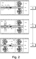
- Figs. 1 and 2 show an example of a method 100 that includes generating fractures.
- the method 100 can include various operational blocks such as one or more of the blocks 101, 102, 103, 104, 105 and 106.
- the block 101 may be a drilling block that includes drilling into a formation 110 that includes layers 112, 114 and 116 to form a bore 130 with a kickoff 132 to a portion defined by a heel 134 and a toe 136, for example, within the layer 114.
- a plug 170 may be introduced into the bore 130 between the heel 134 and the toe 136 and positioned, for example, in a region between first stage perforations of the casing 140 and the heel 134.
- the perforator 160 may be activated to form additional perforations in the casing 140 (e.g., second stage perforations) as well as channels 115-2 in the layer 114 (e.g., second stage channels).
- a plug may be manufactured with properties such that the plug withstands, for a period of time, conditions associated with an operation and then degrades (e.g., when exposed to one or more conditions).
- the plug acts to block a passage for an operation, upon degradation, the passage may become unblocked, which may allow for one or more subsequent operations.
- the method 100 may employ one or more grips, which may optionally include one or more degradable grips.
- a component may be degradable (e.g., a grip or other type of component) upon contact with a fluid such as an aqueous ionic fluid (e.g., saline fluid, etc.).
- a component may be degradable upon contact with well fluid that includes water (e.g., consider well fluid that includes oil and water, etc.).
- a component may be degradable upon contact with a fracturing fluid (e.g., a hydraulic fracturing fluid).
- Fig. 15 shows an example plot 1500 of degradation time versus a component dimension for various temperatures where a component is in contact with a fluid that is at least in part aqueous (e.g., include water as a medium, a solvent, a phase, etc.).
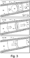
- the plug 350 may be seated such that the bore 346 (e.g., of a first zone) is separated (e.g., isolated) from the bore 348 (e.g., of a second zone) such that fluid pressure in the bore 346 (see, e.g., P 2 ) may be increased to a level beyond fluid pressure in the bore 348 (see, e.g., P 1 ).
- the plug 350 and the plug component 360 are degradable, for example, upon contact with fluid that may pressurize the bore 348, degradation of the plug 350 and the plug component 360 may transition the equipment from the state 301 to the state 302.
- the plug 350, the plug component 360 and the ring component 370 may be components of a dissolvable plug and perforation system that may be used to isolate zones during stimulation (see, e.g., the method 100 of Figs. 1 and 2 ).
- Such equipment may be implemented in, for example, cemented, uncemented, vertical, deviated, or horizontal bores (e.g., in shale, sandstone, dolomite, etc.).
- the plug component 360 and the ring component 370 may be conveyed in a bore via a pump down operation (e.g., which may move the components 360 and 370 along a bore axis direction).
- a component or components may include adjustable features, for example, that allow a change in diameter to facilitate seating in a receptacle disposed in a bore.
- a tool may interact with a component or components to cause a change in diameter or diameters (e.g., a change in form of one or more components).
- the component or components may catch and seat in a receptacle disposed in a bore (e.g., seat in a shoulder of a receptacle component).
- the plug component 360 and the ring component 370 may be seated in a receptacle by a tool that may include one or more perforators. Once seated, the tool may be repositioned to perforate casing and form channels (e.g., in a layer or layers of rock). As an example, repositioning may occur multiple times, for example, to form multiple sets of perforations and multiple sets of channels. As an example, after perforating and channel formation, the plug 350 may be pumped down to contact the plug component 360 and/or the ring component 370, for example, to form a seal that can isolate one zone from another zone (e.g., one interval from another interval).
- a seal that can isolate one zone from another zone (e.g., one interval from another interval).
- one or more grips made at least in part of degradable material may be employed.
- the plug 350, the plug component 360 and the ring component 370 as including a grip or grips made at least in part of degradable material.
- the ring component 370 may include a grip or grips that can accept force and/or apply force with respect to one or more other components.
- the plug component 360 may be made of a plurality of parts where one or more interfaces between two or more of the parts may include a grip or grips.
- particulate material may be substantially spherical.
- particulate material made from gas atomization may be substantially spherical.
- Such particulate material may enhance "packing" of such material (e.g., as to form a matrix, etc.).
- particulate material may be classified by particle size, for example, using FEPA grit sizes or other sizes (e.g., dimension, etc.).
- degradable particular material may be a microgrit material, for example, of an average or median grit size of about F230 or less (e.g., consider about 53 microns based on the average of D50).
- a degradable particulate material classified with a grit size of about F1000 e.g., about 4.5 microns based on the average of D50).
- a model may consider multimodal packing. For example, consider voids of larger particles packed with smaller particles, whose voids in turn may optionally be filled with even smaller particles, etc. (e.g., a form of geometrical progression).
- a population of particles with a progressive particle size distribution may be separated into populations or, for example, separate populations of particles may be combined to form a progressive PSD (e.g., optionally a continuous PSD such as a power law PSD).
- PSD may be Gaussian or another type of mathematical/statistical distribution.
- a method can include providing a blend of materials where the materials include a non-degradable material that is not degradable in an aqueous environment and an aqueous degradable alloy material.
- the provision block 410 of the method 400 can provide the aqueous degradable alloy material and the provision block 420 can provide the non-degradable material that is not degradable in an aqueous environment, which, per the provision block 420, can be a hard material.
- it may be a hard material that has a hardness that is in excess of a hardness of low alloy steel (LAS).
- a blend of materials can include an amount of aqueous degradable alloy that is sufficient to form a matrix for an amount of non-degradable material that is not degradable in an aqueous environment.
- an amount of aqueous degradable alloy may be from about 10 percent by weight to about 90 percent by weight and an amount of non-degradable material that is not degradable in an aqueous environment may correspondingly be from about 90 percent by weight to about 10 percent by weight.
- Table 1 Cemented carbide Hardness HV (RT) Modulus GPa Traverse ru ptu re strength MPa Coefficient of thermal expansion, 10 -6 /K Thermal conductivity, W/m.K Density g/cm 3 WC-20 wt% Co 1050 490 2850 6.4 100 13.55 WC-10 wt% Co 1625 580 2280 5.5 110 14.50 WC-3 wt% Co 1900 673 1600 5.0 110 15.25 WC-10 wt% Co-22 wt% (Ti,Ta,Nb)C 1500 510 2000 6.1 40 11.40
- Tungsten carbide as WC with a hexagonal crystal structure, can possess a hardness of about 2200 HV (50 kg) and a melting temperature of about 2800 degrees C with a density of about 15.6; while tungsten carbide as W 2 C, with a hexagonal crystal structure, can possess a hardness of about 3000 HV (50 kg) and a melting temperature of about 2777 degrees C with a density of about 17.3.
- a metal matrix composite (MMC) material can include from about 1 percent to about 15 percent by weight of ceramic powder(s) mixed with an aqueous degradable alloy where such a MMC material can exhibit improved hardness and higher modulus (e.g., consider an example at about 14 percent by weight).
- a method can include formulating a blend such that a volume percent of particulates may be greater than about 80 percent, for example, of ceramics and/or iron (Fe) based alloy powders that are bound by an aqueous degradable alloy.
- a material can be a solid with hardness adequate to bite or anchor into an LAS casing.
- a non-degradable material that is not degradable in an aqueous environment can be a material that includes covalent bonds.
- a material can be a network solid or covalent network solid that is a chemical compound (e.g., or element) in which atoms are bonded by covalent bonds in a continuous network extending throughout the material.
- a network solid there may be no substantial presence of individual molecules such that an entire crystal may be considered a macromolecule.
- a network solid material can be or include diamond with a continuous network of carbon atoms and/or silicon dioxide (e.g., quartz) with a continuous three-dimensional network of SiO 2 units; noting that graphite and the mica group of silicate minerals structurally include continuous two-dimensional sheets covalently bonded within the layer, with other bond types holding the layers together.
- silicon dioxide e.g., quartz
- a network solid material can be very hard due to strong covalent bonds throughout a lattice; can have a high melting point as melting means breaking covalent bonds; may be poor electrical conductors where electrons are used for sigma bonds (e.g. diamond and quartz) due to little to no delocalized electrons; can be generally insoluble (e.g. due to difficulty of solvating a very large molecule).
- a network solid material such as diamond or silicon dioxide can be considered to be non-degradable materials that are not degradable in an aqueous environment as may exist in a downhole environment or operation in a downhole environment.
- the process block 430 can include one or more processes that can form a component.
- a process can include one or more types of surface treatment processes such as, for example, sintering and/or nitriding.
- a method can include providing a blend of materials and pressing the blend of materials where the materials include a non-degradable material that is not degradable in an aqueous environment and an aqueous degradable alloy material; and forming a degradable grip from the pressed blend of materials.
- a hard material can be, for example, a polycrystalline diamond material or a cubic boron nitride material.
- processing can include pressing such as utilized in making pieces of polycrystalline diamond (PCD) or pieces of polycrystalline cubic boron nitride (PCBN).
- PCD polycrystalline diamond
- PCBN polycrystalline cubic boron nitride
- a mixture of materials can be subjected to pressing to form one or more blanks or to form one or more grips directly.
- a pressed blank or grip may be sintered and/or nitrided.
- a grip may be formed from a blank.
- a grip may be formed as an insert or another type of part that can be operatively coupled to another part.
- a metal matrix composite (MMC) material can include a nickel-based super alloy material.
- the MMC material may optionally be nitrided to impart surface properties.
- a degradable grip can include a nitrided surface.
- a nickel-based super alloy can include about 10 to about 20 percent by weight Cr, up to about 8 percent by weight Al and Ti, and about 5 to about 10 percent by weight Co.
- a nickel-based super alloy may include one or more amounts of one or more other elements (e.g., B, Zr, C, Mo, W, Ta, Hf, and Nb).
- nitriding may be implemented as a heat treating process that acts to diffuse nitrogen into a surface of a metallic material, for example, to create a case-hardened surface.
- nitriding may include laser nitriding and/or another form of nitriding.
- a degradable metal-based material can be utilized to form a matrix for a hard material to form a metal matrix composite material.
- the metal matrix composite (MMC) material may be shaped as a grip that can be utilized to anchor one component with respect to another component.
- a method can include increasing a volume fraction of particulates where, for example, more than about 80 percent by volume of ceramic and/or iron-based alloy powder are bound by a degradable alloy.
- a consolidated material can possess adequate hardness to bite or anchor into a LAS casing.
- hardness of such a material e.g., a MMC material
- nitriding may slow near surface dissolution rate of such a material.
- the deployment block 440 can include disposing one or more components in a downhole environment and degrading at least a portion of one of the one or more components in the downhole environment.
- the deployment block 440 may also include ageing of one or more components in an environment or environments in which a component or components may be deployed. As an example, ageing can include heat treating.
- one or more degradable components may be implemented in one or more tools, pieces of equipment, etc., for example, to achieve temporary anchoring (e.g., static and/or dynamic).
- an operation that performs multistage stimulation may employ one or more degradable elements, optionally as triggering components.
- degradation of an element may trigger slippage of one or more components with respect to one or more other components.
- the method 550 includes a provision block 554 for providing a powder mixture A, a formation block 558 for forming a base from the powder mixture A, a provision block 562 for providing a powder mixture B, a formation block 566 for forming one or more grips from the base and from the powder mixture B, a formation block 570 for forming an assembly and a deployment block 574 for deploying the assembly.
- a non-degradable grip portion may be dimensioned such that it may be unlikely to interfere with one or more operations.
- a grip portion may include a maximum cross-sectional dimension of about 10 mm or less and be of an axial length of about 30 mm or less.
- a grip portion may include a maximum cross-sectional dimension of about 5 mm or less and be of an axial length of about 15 mm or less.
- a grip portion may include a maximum cross-sectional dimension of about 3 mm or less and be of an axial length of about 6 mm or less.
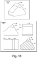
- a grip can include a base portion with dimensions of about 6 mm (e.g., height) by about 6 mm (e.g., axial length) by about 7 mm (e.g., width) with a grip portion of about 2 mm (e.g., height) by about 6 mm (e.g., axial length) by about 2 mm (e.g., width).
- a method can include pressing at high pressure and high temperature for form a stock piece followed machining such as, for example, EDM cutting, which may form one or more components from the stock piece.
- the stock piece may be formed at least in part from tungsten carbide powder (e.g., consider a grain size of about 0.6 micron) where the stock piece includes a dissolvable powder alloy, which can be present at a lesser weight percent than the tungsten carbide powder.
- a stock piece can include multiple regions where, for example, one or more regions can include a hard material such as, for example, polycrystalline diamond (PCD).
- PCD polycrystalline diamond
- such hard material may form a tip, which may be part of a ridge, a tooth, etc.
- a grip can include multiple regions where two or more of the regions possess different compositions.
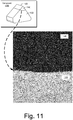
- Fig. 6 shows an example of an illustration of a metal matrix composite (MMC) material 600 that include degradable material 610 and hard material 630, which can be hard, non-degradable material. As shown, the degradable material 610 can form a matrix for the hard material 630.
- MMC metal matrix composite
- the grip 1000 can include an interface between the base portion 1030 and the grip portion 1040 where material of the base portion 1030 and material of the grip portion 1040 are bonded.
- bonding may occur responsive to, for example, pressure and/or temperature (e.g., applying pressure to and/or heating the grip 1000).
- Fig. 15 shows an example of an assembly 1500 that includes grips 1510.
- the grips 1510 may be arranged about a circumference of a portion of the assembly 1500.
- the grips 1510 can include degradable grips, which may optionally include one or more non-degradable portions (e.g., consider non-degradable tip(s)).
- Fig. 16 shows an example of a disc 1600 that is made of two materials with different compositions such that grips may be made from the disc 1600 where the grips include the two materials with different compositions.
- the disc 1600 can include an annular portion 1602 and a cylindrical portion 1604 where the annular portion 1602 is made of a first material with a first composition and the cylindrical portion 1604 is made of a second material with a second composition.
- the first and second materials may include a fusible metal such as, for example, cobalt.
- a fusible metal can bond the first and second materials about an interface defined by an outer surface of the cylindrical portion 1604 and an inner surface of the annular portion 1602.
- Fig. 18 shows an example of a method 1850 that includes a provision block 1854 for providing a dissolvable material (e.g., a degradable material that can degrade in an aqueous environment), a formation block 1858 for forming a base (see, e.g., the base 1859), a provision block 1862 for providing a hard material, a formation block 1866 for forming a stock composite piece (see, e.g., the stock composite piece 1867), and a formation block 1870 for forming one or more grips (see, e.g., the grips 1871) from the stock composite piece.
- a dissolvable material e.g., a degradable material that can degrade in an aqueous environment
- a formation block 1858 for forming a base
- a provision block 1862 for providing a hard material
- a formation block 1866 for forming a stock composite piece
- a formation block 1870 for forming one or more grips (see, e
- Fig. 19 also shows an example of an assembly 1970 that includes a component 1972, a component 1974 and a grip 1975.
- the components 1972 and 1974 may be cylindrical or may be planar or may be of another type of geometry.
- a grip may be utilized with respect to cylindrical, planar or one or more other types of geometries.
- a grip or grips may be fit to a biasing mechanism.
- a spring can include grips where the spring may force the grips against one or more other components.
- a spring may be a stabilizer spring that may be akin to a leaf spring that may extend from a tubular component to stabilize its position within another tubular component.
- stabilizer springs may guide a component with an ability to move the component with less friction than when the grips are present (e.g., in a non-degraded state).
- a centralizer may include one or more grips.
- a stabilizer may include one or more grips.
- a downhole tool can include one or more grips.
- a downhole tool string can include one or more grips.
- a slip can include one or more grips.
- a grip or grips can be a gripping toothed device or assembly that can grip one or more components and, for example, locate at least one component with respect to at least one other component, for example, to axially locate at least one of the components in a borehole, etc.
- such alloys may be characterized by considerable resistance to corrosion, high thermal and electrical conductivity, low mechanical properties and workability, while tending to be non-heat treatable.
- a degradable alloy can include one or more alloying elements "trapped" in "solid solution".
- a material may include a metal such as aluminum, which may be impeded from passivating or building a resilient protective layer (e.g., aluminum oxide such as Al 2 O 3 ).
- a material may "intentionally" fail via liquid-metal embrittlement, for example, as in an alloy that includes gallium and/or indium.
- a degradable material may include an alloy or alloys and possess phases that may be susceptible to creep (e.g., superplastic) deformation (e.g., under intended force, etc.), possess phases that are brittle (e.g., which may rupture in response to impact, etc.).
- a material may include one or more magnesium-lithium (Mg--Li) alloys, for example, enriched with tin, bismuth and/or one or more other low-solubility alloying elements.
- Mg--Li magnesium-lithium
- a material can include aluminum, gallium and indium.
- a material with an alloy of about 80 weight percent aluminum, about 10 weight percent gallium and about 10 weight percent indium may include Vickers microhardness (500 g) of about 32 (#1), 34 (#2), 34 (#3), 30 (#4), 35 (#5), 36 (#6) and 33 (average) and estimated strength of about 100 (MPa), 15 (ksi) and 1.5 (normalized).
- a Vickers microhardness test procedure such as, for example, ASTM E-384, can specify a range of loads using a diamond indenter to make an indentation which is measured and converted to a hardness value.
- a square base pyramid shaped diamond can be used for testing in the Vickers scale where, for example, loads can be ranging from a few grams to one or several kilograms; noting that "macro" Vickers loads can range up to 30 kg or more.
- a component may be formed of material that provides a desired degradation rate and desired mechanical properties (e.g., strength, elasticity, etc.).
- a degradation rate may depend upon one or more conditions (e.g., temperature, pressure, fluid environments), which may be exist in an environment and/or may be achieved in an environment (e.g., via one or more types of intervention).
- a material may be conditionally degradable (e.g., degradable upon exposure to one or more conditions).
- a component may have an operational lifetime in a wellbore that is less than about 8 hours and then age in a manner at least in part thermally that causes the component to fail more readily.
- ageing may assist with degradation, for example, via one or more failure mechanisms (e.g., elongation to failure, etc.).
- a method can include using a blend of un-milled coarse powder(s) with a cryomilled-blend of water reactive or degradable powder (e.g., in a range of about 5 percent to about 95 percent) and one or more ceramic dispersoids (e.g., SiC, B 4 C, Al 2 O 3 , etc.).
- a cryomilled-blend of water reactive or degradable powder e.g., in a range of about 5 percent to about 95 percent
- one or more ceramic dispersoids e.g., SiC, B 4 C, Al 2 O 3 , etc.
- the system 2200 includes a vacuum induction furnace 2210, an optional heat exchanger 2212 (HX), a chamber 2216, a cyclone chamber 2218, and a nozzle 2250.
- HX heat exchanger
- a rapid expansion of the gas 2230 as provided to the nozzle 2250 can break up the melt 2220, which may form a thin sheet and subsequently ligaments, ellipsoids and/or spheres (e.g., particles).
- particles formed may be substantially spheroidal.
- an atomization process may be a gas atomization process (e.g., including inert and/or non-inert gas), a water atomization process, a mechanical pulverization process, etc.
- Particles may be collected in the chamber 2216 and in the cyclone chamber 2218, which can allow gas to exit and optionally recycle (e.g., with make-up gas, etc. to maintain a gas composition where multiple gases may be used).
- the cyclone chamber 2218 may collect particles that are finer than the particles collected in the chamber 2216. Particles of either or both chambers 2216 and 2218 may be combined, separated, etc.
- the system 2200 may include multiple cyclones, which may be in parallel and/or in series.
- the system 2200 may include a cyclone in fluid communication with the cyclone 2218.
- particles collected e.g., powder particles
- a melt temperature may be a superheated temperature.
- a melt temperature may be greater than about 650 degrees C (e.g., greater than about 700 degree C and optionally greater than about 800 degrees C).
- a chamber such as the chamber 716 may be at a temperature of about 70 degrees C (e.g., a temperature of the order of hundreds of degrees C less than a melt temperature).
- gas may expand relatively adiabatically, which may facilitate cooling of melt and reducing thermal shock.
- a method may include cooling melt at a rate that causes at least a portion of a particle formed from the melt to be amorphous.
- a method may include cooling via a cryogenic cooled target (e.g., consider the heat exchanger 2212 of the system 2200).
- a cryogenic cooled target may be positioned in front of an atomizing nozzle, for example, to achieve a cooling rate (e.g., Rc) where vitrification occurs for atomized (melt) droplets (e.g., to be at least in part a metallic glass structure, which may be a bulk metallic glass structure).
- a material may be characterized at least in part by a glass transition temperature (T g ) where below that temperature an amorphous material may be glassy (e.g., whereas above T g it may be molten).
- a melt may be analyzed as to one or more properties such as, for example, a glass-transition or vitrification temperature (e.g., T g ).
- T g glass-transition or vitrification temperature
- a system may be operated such that transformation takes place at the glass-transition temperature, T g , below an equilibrium temperature for the solidification (e.g., a liquidus temperature, T L ), which may act to "freeze" an atomized melt in a non-equilibrium state (e.g., at least in part as an amorphous material).
- a liquidus temperature may be the maximum temperature at which crystals can co-exist with a melt in thermodynamic equilibrium.
- a method may consider a solidus temperature (Ts) that quantifies a point at which a material crystallizes.
- Ts solidus temperature
- a gap may exist between its liquidus and solidus temperatures such that material can include solid and liquid phases simultaneously (e.g., akin to a slurry).
- a method may include cooling a melt to produce an amorphous melt-span ribbon.
- the ribbon may be further processed, for example, by mechanical crushing of the ribbon to form a powder.
- a water reactive powder e.g., a degradable powder
- the powder may be produced by gas atomization (e.g., using one or more gases, optionally one or more inert gases), by ball milling, by crushing or other mechanical means, by sol-gel, etc.
- a powder may include particles of one or more particle size distributions. For example, consider D90 less than about 44 microns (e.g., a mesh size of about 325), D90 less than about 60 microns, D90 less than about 90 microns, etc.
- a material may be subjected to one or more SPD processes.
- a method can include employing one or more SPD processes.
- a method can include shearing of grains in consolidated or unconsolidated powder through a channeled die at low to high angles.
- ECAP can include passing material through a die (e.g., or dies) at various angles, which may abet refining of grains (e.g., of a water reactive powder), for example, to achieve a desired minimum grain size (e.g., after a certain number of ECAP passes).
- a method can include ECA pressing, for example, at one or more temperatures.
- a method can include performing ECAP to abet refining of grains, for example, to achieve a minimum grain size (e.g., after a certain number of ECAP passes).
- a method can include performing cryomilling to abet refining of grains, for example, to achieve a minimum grain size (e.g., after a certain duration of milling).
- a method can include performing HPT to abet refining of grains, for example, to achieve a minimum grain size (e.g., after a certain number of HPT turns or revolutions).
- a method can include performing cold working to abet refining of grains, for example, to achieve a minimum grain size (e.g., after a certain percentage of cold working).
- a method may include controlling grain size. For example, consider alternating grain size from the point of inflection of an inverse Hall-Petch trend (e.g., varying for different alloys, consider about 50 nm) to an upper limit of ultrafine grains (e.g., about 1000 nm or 1 micron).
- a method can include controlling grain size by controlling one or more parameters of one or more SPD processes (e.g., cryomilling time, ECAP passes, HPT turns or revolutions, percentage of cold work, etc.).
- a method can include processing water reactive powder via one or more SPD processes, for example, to tailor dissolution rate in a fluid, to tailor dissolution rates in various fluids, etc.
- a fluid may be a hydraulic fracturing fluid.
- a fluid may include a salt concentration or concentrations of salts.
- a fluid may be an aqueous fluid.
- Such an aqueous fluid may include one or more salts.
- a method may include varying percentages of one or more inhibited acid that may be used in one or more spearheading operations during hydraulic fracturing.
- a method can include tailoring dissolution rate (e.g., degradation rate) by controlling grain size.
- dissolution rate e.g., degradation rate
- one or more SPD processes may be used for refining grains, for example, to achieve a minimum grain size (e.g., optionally altering grain size from the point of inflection of an inverse Hall-Petch trend).
- dissolution rate may be influenced by disruption of a continuous grain boundary network.
- One or more characteristics of such a network may be influenced by one or more SPD processes.
- dissolution rate e.g., degradation rate
- dissolution rate may be influenced by precipitation of an additional phase of dispersoids, for example, as may be processed during one or more other SPD processes.
- a gas atomization process can generate particles that may be characterized at least in part by size (e.g., consider a size distribution of about 10 microns to about 20 microns).
- grains in particles may be of the order of about a micron.
- particles may be formed via gas atomization that include grains of the order of less than about one micron (e.g., optionally less than about half a micron).
- a method may include one or more of the following processes and/or produce a material that includes one or more properties listed below (e.g., of a desired high strength degradable alloy): inert gas atomization (IGA) of a brittle cast melt with controlled flow through one or more nozzles (e.g., optionally of varying sizes) to yield powder particles of varying mesh size; particulate (approximately 80 percent to approximately 100 percent (e.g., approximately 90 percent) screened distribution) with sizes varying between about 10 microns and about 70 microns (e.g., between about 20 microns and about 60 microns).
- IGA inert gas atomization
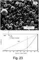
- Fig. 23 shows a scanning electron micrograph 2300 of particles produced via gas atomization of a brittle cast melt.
- Such particles may be formed by cooling the melt as it exits a nozzle (see, e.g., the nozzle 2250 of the system 2200 of Fig. 22 ).
- Such cooling may be adiabatic cooling.
- adiabatic cooling can occur when pressure on an adiabatically isolated system is decreased, allowing it to expand, thus causing it to do work on its surroundings.
- the pressure applied on a parcel of gas is reduced, the gas in the parcel is allowed to expand; as the volume increases, the temperature falls as internal energy decreases.
- a gas atomization process may "capture" melt in a particle as a supersaturated solid solution.
- a particle may include properties that can reduce segregation of alloying constituents in solid solution.
- a gas atomization process may yield fine to ultrafine grain microstructure in particles that form a powder.
- Fig. 23 also shows an example plot 2310 that illustrates an approximate relationship between dissolution rate and percent of a first material versus one or more other materials (e.g., a second material, a third material, etc.).
- a plot may exhibit one or more approximate relationships between amounts or percentages of materials and hardness and/or dissolution rate.
- a composite material may be formulated for making a degradable grip with a desired hardness and a desired dissolution rate when exposed to an aqueous environment (e.g., a downhole aqueous environment).
- Fig. 24 shows an example of a transmission electron micrograph (TEM) 2400 of a particle of a powder.
- the TEM 2400 shows ultrafine grains with darker grain boundaries; noting focus ion beam (FIB) sample preparation. Specifically, the TEM 2400 shows that the particle includes grains with dimensions of the order of about one micron or less.
- the TEM 2400 shows various grains that include dimensions of about 0.5 microns.
- a process can generate particles with grains where, for example, the processing provides for segregation of one or more low melting point constituents at grain boundaries.
- the one or more low melting point constituents can coat grains and through such coating form a galvanic couple.
- a process may provide for weakening of grain boundary interfaces in a component formed of a powder produced via gas atomization, which may help to promote embrittlement of the boundaries and further enhance a degradation mechanism (e.g., or degradation mechanisms).
- a degradation mechanism e.g., or degradation mechanisms.
- a particle of a material that includes aluminum and gallium where gallium enrichment at grain boundary interfaces may promote embrittlement of the boundaries and where at least gallium interacts with fluid in a manner that causes degradation of the particle.
- a component formed of such particles e.g., via processing of such particles
- a material may include one or more oxide dispersoids, which may provide enhanced thermal stability and strengthening, for example, due to pinning of grain boundaries and dislocations.
- differential cooling of a warm powder may abet diffusion of one or more low melting point constituents from a trapped supersaturated solid solution to a grain interior along a grain boundary, for example, causing liquid-metal embrittlement, which may enhance a degradation mechanism (e.g., consider a mechanism where gallium interacts with fluid in a manner that causes degradation).
- Fig. 25 shows an example of a TEM 2500 that includes a triple junction between three grains (e.g., a GBTP) in a particle of a powder.
- the TEM 2500 shows contrast and compositional differences between the grain boundary and the grain; noting focus ion beam (FIB) sample preparation.
- the TEM 2500 includes two windows that correspond to samples: Sample 1 for grain material composition and Sample 2 for grain boundary material composition.
- a method can include energy-dispersive X-ray (EDX) analysis of composition of a sample (e.g., Sample 1 of the TEM 2500 and Sample 2 of the TEM 2500).
- EDX is an analytical technique that can be applied for elemental analysis or chemical characterization of a sample.
- EDX involves interaction of a source of X-ray excitation (e.g., electrons) and a sample where, for example, a number and energy of X-rays emitted from the sample can be measured by an energy-dispersive spectrometer (e.g., EDS).
- EDS energy-dispersive spectrometer
- energy of X-rays can be characteristic of the difference in energy between two shells, and of the atomic structure of an element from which they were emitted, this allows the elemental composition of the sample to be measured.
- material at a grain boundary may be enriched in gallium when compared to material in a grain.
- material at a grain boundary may be enriched in indium when compared to material in a grain.
- material at a grain boundary may be enriched in gallium and indium when compared to material in a grain.
- a particle may include material at a grain boundary that, upon analysis, generates gallium counts at one or more energies of less than about 2 keV and generates counts gallium counts at one or more energies greater than about 8 keV.
- a ratio of counts may be about two to one.
- such a particle may include material at a grain boundary that, upon analysis, generates indium counts at energies from about 2 keV to about 5 keV. In such an example, such counts may be less than counts of a maximum gallium count at an energy greater than about 8 keV and less than counts of a maximum gallium count at an energy less than about 2 keV.
- one or more ceramic and/or other particulates may be added to a powder (e.g., or powders) to form a metal matrix composites (MMC) material.
- a powder e.g., or powders
- MMC metal matrix composites
- An alloy can include crystalline, amorphous or mixed structure (e.g. partially crystalline, partially amorphous).
- Features characterizing the structure can include grains, grain boundaries, phases, inclusions, etc.
- one or more features may be of the order of macroscopic, micron or submicron scale, for instance nanoscale. Shape, size, shape and size, etc. may be characteristics that can influence mechanical properties and, for example, reactivity.
- a reactive material may include an element that tends to form positive ions when its compounds are dissolved in a liquid solution and whose oxides form hydroxides rather than acids with water.
- a material may disintegrate. For example, consider an alloy that loses structural integrity and becomes dysfunctional for instance due to grain-boundary embrittlement or dissolution of one of its elements.
- a byproduct of degradation from grain boundaries may not necessarily include an ionic compound such as a hydroxide and may include a metallic powder residue (e.g., consider severely embrittled aluminum alloys of gallium and indium).
- a material may be electrically conductive and may include a metallic luster.
- a material may be degradable and, for example, an alloy may be degradable (e.g., a degradable alloy).
- a material may degrade when subject to one or more conditions (e.g., over time). For example, consider one or more environmental conditions and/or "artificial" conditions that may be created via intervention, whether physical, chemical, electrical, etc.
- conditions can include temperature, pressures (e.g., including loads and forces), etc.
- a component may be made from a blend of particulate materials that include at least one age-hardenable particulate material.
- the blend can include one or more degradable particulate materials and one or more non-degradable particulate materials.
- a component may be age-hardened prior to deployment, during deployment and/or after deployment.
- a blend of particulate materials can include an aluminum alloy that may be an age-hardenable aluminum alloy.
- the blend can include particulate material that is degradable, for example, when exposed to an aqueous environment.
- a component may be formed of a blend of materials where the component is age-hardenable and degradable in an aqueous environment (e.g., a downhole environment that includes water).
- a material can include cryomilled nanocrystalline grains, which may be thermally stable.
- a cryomilled nano and/or UFG solid may be thermally stable up to about 0.8 of an alloy's melting point.
- a method can include thermal treatment of a water reactive or degradable alloy, which may be mixed with one or more polymeric materials to form a component.
- a method may include making a blend of cryomilled and un-milled particulate material.
- the method can include solution annealing, which may act to put coarse un-milled grains into solution and promote precipitate hardening during an ageing cycle in an annealed fraction.
- cryomilled nano grains may be retained from going into solution due to their enhanced thermal stability, however, growth may occur to a multimodal nano and/or UFG size abetting ductility to the blended solid.
- a thermal treatment (e.g., one or more of solution annealing, ageing, etc.) may be applied during and/or after formation of a consolidated polymeric material from a blend of un-milled gas atomized powder with cryomilled gas atomized (GA) powder.
- an un-milled GA powder can be a water reactive powder.
- an un-milled GA powder can be formed of a melt of a heat treatable aluminum alloy series (e.g., consider 6XXX and/or 7XXX series).
- a cryomilled GA powder can be water reactive powder (e.g., degradable in an aqueous environment).
- a cryomilled GA powder can be formed of a melt of a heat treatable aluminum alloy series (e.g., consider 6000, 7000 series).
- a blend can be stabilized by ceramic particulates (e.g., SiC, B 4 C, Al 2 O 3 , etc.) to produce a metal matrix composite (MMC).
- MMC metal matrix composite
- addition of ceramic particulates may be before cryomilling or, for example, during blending of un-milled and cryomilled GA powders.
- a method can include blending GA powders that can have different, close or similar peak age properties and thermal cycles.
- a method can include solution annealing of a bulk solid consolidated from blended cryomilled and un-milled powders.
- solution annealing may aim to put un-milled component(s) (e.g., coarse grained) into solution (e.g., for a set time duration) while retaining structure of highly thermally stable cryomilled (e.g., nano grain) counterparts; noting that some grain growth may occur in nano-cryomilled grains, for example, transforming them to nano and/or ultra-fine duplex grains, which may abet additional ductility post thermal treatment.
- un-milled component(s) e.g., coarse grained
- solution e.g., for a set time duration
- highly thermally stable cryomilled e.g., nano grain counterparts
- a metal powder may be manufactured via one or more techniques, for example, depending on type of metal and alloy and desired properties.
- a powder may be manufactured by reduction of oxides and other chemical techniques; atomization of metallic melts; pulverization of solids; electrolysis of water solutions or molten salts; etc.
- dense particles of different chemical composition may be obtained by atomizing molten metal or alloys.
- a metal stream can be atomized by process that may include one or more of atomizing in water, air, or an inert gas (e.g., argon or nitrogen).
- a powder may be screened and, for example, subject to heat under a reducing atmosphere (e.g., consider surfaces of particles that are oxidized).
- a reducing atmosphere e.g., consider surfaces of particles that are oxidized.
- an atomization process may be employed to obtain one or more alloy powders, which may include an even distribution of alloying metals in the volume of each particle.
- a PM alloy may circumvent segregation associated with ingot metallurgy (IM) product (casting etc.), where cooling from a molten state tends to be relatively slow, which may be detrimental to workability, etc.
- IM ingot metallurgy
- an increased cooling rate may be employed compared to an IM process where, for example, the increased cooling rate may result in an extension of solid solubility limits that can lead to larger volume fractions of finer second-phase particles and/or formation of metastable phases.
- a PM process may produce relatively homogeneous powder particles with substantial uniformity and with fine microstructure. Such characteristics may result enhanced mechanical properties.
- an extension of phase fields and creation of additional phases can relate to supercooling, as achieved via one or more powder metallurgy techniques.
- microstructural refinement can occur in part due to reduced diffusion distances.
- rapid cooling via a PM process can result in an increased tolerance to trapped elements (e.g., compared to material obtained via an IM process).
- trapped elements e.g., compared to material obtained via an IM process.
- material may experience reduced segregation, especially as to sites such as grain boundaries.
- a method can include blending powders from different alloys where, for example, an alloy may be age-hardenable or non-age-hardenable and/or degradable or non-degradable.
- an aluminum alloy may be selected from the 5000 series or from the 7000 series.
- a blend of powders can include particles with nanocrystalline grains.
- a blend of powder can include milled particles, for example, mechanically milled particles (e.g., consider cryomilling).
- a blend of powders can include one or more dispersoids.
- a method can include tailoring dissolution of a component.
- a method may include blending powders of one or more non-degradable alloys with one or more degradable powders.
- a method can include blending of water reactive or degradable powder with one or more other powders where the water reactive or degradable powder is in a range of about 5 percent to about 95 percent of the weight of a blend.
- a powder may be an age-hardenable non-degradable powders (e.g., consider aluminum 6000 and 7000 series); may be a strain hardenable non-degradable powders (e.g., consider aluminum 5000 series, etc.); may be a powder that includes highly thermally stable nanocrystalline grains processed by cryomilling; may be a powder that includes highly thermally stable nanocrystalline grains processed by cryomilling that are further stabilized by dispersoids (e.g., SiC, B 4 C, Al 2 O 3 , etc.), for example, to produce a metal matrix composite (MMC) material; etc.
- MMC metal matrix composite
- a method can include blending water reactive or degradable powder with material that includes highly thermally stable nanocrystalline grains processed by cryomilling and optionally further blending dispersoids (e.g., SiC, B 4 C, Al 2 O 3 , etc.).
- dispersoids e.g., SiC, B 4 C, Al 2 O 3 , etc.
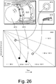
- Fig. 26 shows an example plot 2600 of component dimension versus time of degradation for various temperatures and an example of an assembly 2610 that includes components 2612, 2614 and 2615 that may be made by consolidating particulate materials and example grips 2616 and 2618, which may optionally be included in an assembly such as, for example, the assembly 2610.
- a component may be constructed to include one or more layers where at least one layer includes a degradable material, which may include a dimension (e.g., thickness, etc.) that is based at least in part on information such as the information of the plot 2600 of Fig. 26 .
- a layer may be a nitrided layer and/or a sintered layer.
- a degradable grip can include a sintered and/or a nitrided layer.
- a grip can include a non-degradable portion or portions.
- the assembly 2610 may include one component that degrades at a rate that differs from another component.
- the plug component 2612 e.g., a ball, etc.
- the plug seat component 2614 e.g., a ring that can include a plug seat and that may act to locate the plug seat.
- the assembly 2610 can include a plurality of pieces where such pieces may be formed according to desired dissolution rate, strength and/or ductility.
- one or more of the pieces of the assembly 2610 can be or include a grip.
- the component 2614 can include grips as teeth, buttons, ridges, etc.
- the component 2615 may be a sub-assembly that includes one or more grips (e.g., as teeth, buttons, ridges, etc.).
- equipment associated with one or more types of downhole operations can include one or more types of degradable grips.
- a liner may be a casing (e.g., a completion component).
- a liner may be installed via a liner hanger system.
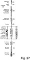
- a liner hanger system may include various features such as, for example, one or more of the features of the example assembly 2750 of Fig. 27 .
- the assembly 2750 can include a pump down plug 2760, a setting ball 2762, a handling sub with a junk bonnet and setting tool extension 2764, a rotating dog assembly (RDA) 2766, an extension(s) 2768, a mechanical running tool 2772, a hydraulic running tool 2774, a hydromechanical running tool 2776, a retrievable cementing bushing 2780, a slick joint assembly 2782 and/or a liner wiper plug 2784.
- RDA rotating dog assembly
- a plug may be an object that can be seated, for example, to seal an opening.
- the pump down plug 2760 and the setting ball 2762 may be plugs.
- a plug tool may be a tool that includes at least one seat to seat a plug.
- a plug tool may include a seat that can seat a plug shaped as a ball (e.g., a spherical plug), as a cylinder (e.g., a cylindrical plug), or other shaped plug.
- an assembly may include a liner top packer with a polished bore receptacle (PBR), a coupling(s), a mechanical liner hanger, a hydraulic liner hanger, a hydraulic liner hanger, a liner(s), a landing collar with a ball seat, a landing collar without a ball seat, a float collar, a liner joint or joints and/or a float shoe and/or a reamer float shoe.
- PBR polished bore receptacle
- a method can include a liner hanger setting procedure.
- a procedure may include positioning a liner shoe at a depth at which a hanger is to be set, dropping a setting ball from a ball dropping sub of a cementing manifold, gravitating or pumping the ball down to a ball catch landing collar, reducing the pump rate when the ball is expected to seat, increasing pressure, which pressure may act through setting ports of a hanger body and set slips on to a casing, and while holding the hanger setting pressure, setting the liner hanger by slacking off the liner weight on the hanger slips, where a loss of weight may be indicated on a weight gauge as the liner hanger sets.
- the ball has properties suited for one or more operation or operations.
- Properties may include mechanical properties and may include one or more other types of properties (e.g., chemical, electrical, etc.).
- a ball may be manufactured with properties such that the ball degrades when exposed to one or more conditions (e.g., consider environmentally-assisted cracking). In such an example, where the ball acts to block a passage, upon degradation, the passage may become unblocked.
- a ball or other component e.g., a plug, etc.
- one or more components of the assembly 2750 can include a degradable grip or degradable grips that are made at least in part of a degradable material.
- a component or a portion of a component may degrade in stages. For example, consider a plug that degrades from a first size to a second smaller size. In such an example, the second smaller size may allow the plug to move (e.g., from a first seat to a second seat, etc.).
- a plug tool may be a degradable tool.
- a plug tool may be degradable in part (e.g., consider a frangible degradable plug). For example, consider a plug tool with a degradable seat or degradable seats.
- a plug may be seated in a degradable seat that upon degradation of the seat, the plug may pass through the seat (e.g., become unplugged with respect to that seat).
- a system can include a plug tool that is degradable at least in part and one or more degradable plugs (e.g., balls, cylinders, etc.).
- a layer of a plug, a seat, etc. may be a degradable polymeric material layer.
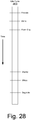
- Fig. 28 shows an example of a life cycle 2810.
- life cycle 2810 various times are illustrated as to stages or phases.
- one or more materials may be provided, a blend may optionally be made of multiple materials, and a blend may be pressed via one or more processes.
- a finished grip may be deployed, utilized and then, at least in part, degraded.
- a component may be formed of material that provides a desired degradation rate and desired mechanical properties (e.g., strength, elasticity, etc.).
- a degradation rate may depend upon one or more conditions (e.g., temperature, pressure, fluid environments), which may be exist in an environment and/or may be achieved in an environment (e.g., via one or more types of intervention).
- a degradable material may be suitable for use in an operation that may include stages.
- stages For example, consider a cementing operation, a fracturing operation, etc.
- a process may be associated with a completion where portions of the completion are constructed, managed, altered, etc. in one or more stages. For example, cementing may occur in stages that extend successively deeper into a drilled borehole and, for example, fracturing may occur in stages.
- a method can include subjecting a material or materials to severe plastic deformation (SPD), for example, resulting in a high defect density and equiaxed ultrafine grain (UFG) sizes (e.g., with a dimension less than about 500 nm or, for example, less than about 300 nm) and/or nanocrystalline (NC) structures (e.g., with a dimension less than about 100 nm).
- SPD severe plastic deformation
- UFG ultrafine grain
- NC nanocrystalline
- a grip may be used, for example, as a component or as a portion of a component in a stage or stages of a fracturing operation.
- a grip may be used as a component or as a portion of a component in a tensile-loaded application, for example, consider a bridge plug, etc.
- a bridge plug may be a tool, for example, a bridge plug tool.
- Such a tool may include one or more seats, which may, for example, provide for seating of one or more plugs.
- a process material may be formed as part of a cable.
- a degradable grip for a cable consider a degradable grip for a cable.
- a component formed from processed material may be a bridge plug.
- a bridge plug may be a downhole tool (e.g., a type of plug tool) that can be located and set to isolate a lower part of a wellbore.
- a bridge plug may be permanent, degradable, retrievable, etc.
- a bridge plug may be tailored to enable a lower wellbore to be permanently sealed from production or temporarily isolated, for example, from a treatment conducted on an upper zone.
- a bridge plug can include one or more degradable grips.
- a part, a component, etc. constructed of a processed material or processed materials may include be a fluid sampling bottle, a pressure housing, a pump shaft, a cable (e.g., wireline, a power cable, etc.), a bridge plug tool, a projectile (e.g., a drop ball, a dart, etc.), a drill stem stabilizer, etc.
- a method can include making a centralizer using processed material.
- a centralizer may exhibit enhanced wear resistance that can reduce surface damage and corrosion fatigue on a borehole assembly (e.g., BHA), for example, thereby increasing BHA lifetime.
- BHA borehole assembly
- reliability may be improved, for example, when drilling over extended deviated lengths.
- a borehole tool may be a tool that is part of a borehole assembly (e.g., "BHA") or borehole system.
- BHA may be a lower portion of the drillstring, including (e.g., from a bottom up in a vertical well) a bit, a bit sub, optionally a mud motor, stabilizers, a drill collar, a heavy-weight drillpipe, a jarring devices (e.g., jars) and crossovers for various threadforms.
- BHA may provide force for a bit to break rock (e.g., weight on bit), survive a hostile mechanical environment and provide a driller with directional control of a borehole.
- an assembly may include one or more of a mud motor, directional drilling and measuring equipment, measurements-while-drilling tools, logging-while-drilling tools or other borehole tools.
- an apparatus can include a shape and material that includes an aluminum alloy that has an average grain size less than about 1 micron or, for example, less than about 500 nanometers.
- the apparatus may be a degradable apparatus.
- such an apparatus may be a degradable plug.
- the degradable plug may include aluminum and gallium and, for example, indium.
- a borehole tool may be a tool such as, for example, a tool operable in a downhole operation.
- a tool such as, for example, a tool operable in a downhole operation.
- a plug as a tool, a plug tool, a centralizer, a sampling bottle, a wireline, a slickline, etc.
- one or more tools can include a degradable grip.
- an alloy may include one or more of the following group 13 elements: aluminum, gallium and indium.
- an alloy may include at least one of the following group 2 elements: magnesium and calcium.
- a method can include providing particulate material that includes an aluminum alloy where the aluminum alloy is at least approximately eighty percent by weight of the first particulate material and that includes one or more metals selected from a group of alkali metals, alkaline earth metals, group 12 transition metals, and basic metals having an atomic number equal to or greater than 31, where the one or more metals selected from the group total at least approximately two percent by weight of the particulate material.
- a particulate material may optionally be blended with one or more other particulate materials. For example, consider blending with a second particulate material that includes at least one aluminum alloy selected from a group of series 2000, 5000, 6000, 7000, and 9000.
- a particulate material can include at least one basic metal having an atomic number equal to or greater than 31 where, for example, the at least one basic metal having an atomic number equal to or greater than 31 is at least approximately two percent by weight of the particulate material.
- particulate material can include gallium (e.g., as a basic metal).
- the gallium can be at least approximately two percent by weight of the particulate material.
- the presence of gallium may make the particulate material a degradable material (e.g., degradable in an aqueous environment).
- gallium may coat grains (e.g., as grain boundary material).
- a particulate material can include indium.
- a particulate material can include gallium and/or indium, which may be present, for example, at at least approximately two percent by weight of the particulate material.
- a particulate material can include at least one group 12 transition metal selected from a group of zinc and mercury.
- a particulate material can include at least one of gallium, indium, tin, bismuth, zinc, mercury, lithium, sodium and potassium.
- a method can include pressing a blend of materials where the materials include a non-degradable material that is not degradable in an aqueous environment and an aqueous degradable alloy material; and forming a grip from the pressed blend of materials.
- the aqueous degradable alloy material can be present as a matrix that can degrade to allow for migration of the non-degradable material, for example, as particles.
- a non-degradable material may be localized as a portion of a grip. For example, consider a grip portion that includes one or more surfaces that are configured to contact a component for purposes of gripping the component (e.g., to position an assembly, etc.).
- a degradable alloy material can include aluminum and one or more metals selected from alkali metals, alkaline earth metals, group 12 transition metals, and basic metals having an atomic number equal to or greater than 31.
- a non-degradable material can be or include polycrystalline diamond (PCD).
- a non-degradable material can be or include polycrystalline cubic boron nitride (PCBN).
- PCBN polycrystalline cubic boron nitride
- a non-degradable material can be or include a network solid material.
- a non-degradable material can be or include a covalent network solid material.
- a non-degradable material can be or include a ceramic.
- a non-degradable material can include a metal such as, for example, cobalt.
- a degradable material can include a metal such as, for example, cobalt.
- cobalt may provide for bonding of a degradable material and a non-degradable material.
- a non-degradable material can be tungsten carbide, which can be considered to be insoluble in water.
- tungsten carbide can be included in a mixture with a degradable material, for example, to form a degradable component, which may be, for example, a degradable grip or a portion of a degradable grip.
- a method can include pressing a blend of materials where the materials include a non-degradable material that is not degradable in an aqueous environment and an aqueous degradable alloy material; and forming a degradable grip from the pressed blend of materials to form a degradable grip with a Vickers hardness in excess of about 100 or, for example, with a Vickers hardness in excess of about 200.
- a method can include pressing a blend of materials where the materials include a non-degradable material that is not degradable in an aqueous environment and an aqueous degradable alloy material; forming a degradable grip from the pressed blend of materials; and, for example, sintering the pressed blend of materials and/or nitriding the pressed blend of materials.
- a method can include forming at least one degradable tooth, forming at least one degradable button, forming at least one degradable ridge, etc.
- a method can include assembling at least a portion of a borehole tool using a degradable grip.
- a degradable alloy material can include aluminum and one or more metals selected from a group of alkali metals, alkaline earth metals, group 12 transition metals, and basic metals having an atomic number equal to or greater than 31.
- one or more metals selected from the group can include at least one basic metal having an atomic number equal to or greater than 31.
- the at least one basic metal having an atomic number equal to or greater than 31 can be at least approximately two percent by weight of the degradable alloy material.
- one or more metals selected from the aforementioned group can include gallium.
- a degradable grip can include a degradable matrix that is degradable in an aqueous environment; and non-degradable particles disposed at least in part within the matrix where the non-degradable particles are not degradable in the aqueous environment.
- the degradable grip can include, for example, one or more of a tooth, a button, or other shaped feature.
- a degradable grip may be of a maximum dimension less than approximately 5 cm.
- the degradable grip can be an integrally formed piece of degradable material with non-degradable particulates therein (e.g., a MMC material).
- the degradable grip may be formed by pressing.
- an assembly can include a plurality of components where at least one of the components is or includes a degradable grip that includes a degradable matrix that is degradable in an aqueous environment and non-degradable particles disposed at least in part within the matrix where the non-degradable particles are not degradable in the aqueous environment.
- the assembly can be a borehole tool.
- an apparatus can include a degradable matrix that is degradable in an aqueous environment; and non-degradable particles disposed at least in part within the matrix where the non-degradable particles are not degradable in the aqueous environment.
- the non-degradable particles can be or include tungsten carbide.
- an apparatus can include a degradable matrix that is degradable in an aqueous environment; and non-degradable particles disposed at least in part within the matrix where the non-degradable particles are not degradable in the aqueous environment.
- the apparatus can include cobalt and, for example, tungsten carbide.
- an apparatus can include a degradable matrix that is degradable in an aqueous environment; and non-degradable particles disposed at least in part within the matrix where the non-degradable particles are not degradable in the aqueous environment.
- the apparatus can be characterizes by a Vickers hardness of at least approximately 1000 or, for example, a Rockwell C scale hardness of at least approximately 60.
- an apparatus can include a degradable matrix that is degradable in an aqueous environment; and non-degradable particles disposed at least in part within the matrix where the non-degradable particles are not degradable in the aqueous environment.
- the apparatus can include a tip, which may be, for example, defined at least in part by a tip length.
- the tip may form a ridge, a tooth, etc. where the tip extends over a length, which may be straight, curved, etc.
- an apparatus can include a degradable matrix that is degradable in an aqueous environment; and non-degradable particles disposed at least in part within the matrix where the non-degradable particles are not degradable in the aqueous environment.
- the non-degradable particles can be included at a weight of approximately 50 percent or more of the combined weight of the degradable matrix and the non-degradable particles; at a weight of approximately 70 percent or more of the combined weight of the degradable matrix and the non-degradable particles; or at a weight of approximately 90 percent or more of the combined weight of the degradable matrix and the non-degradable particles.
- an apparatus can include a degradable matrix that is degradable in an aqueous environment; and non-degradable particles disposed at least in part within the matrix where the non-degradable particles are not degradable in the aqueous environment and where the degradable matrix includes gallium.
- the gallium can be present at a weight of approximately 2 percent or more of the combined weight of the degradable matrix and the non-degradable particles.
- an apparatus can include a degradable matrix that is degradable in an aqueous environment; and non-degradable particles disposed at least in part within the matrix where the non-degradable particles are not degradable in the aqueous environment.
- the apparatus can be a unitary piece.
- an apparatus can include a degradable matrix that is degradable in an aqueous environment; and non-degradable particles disposed at least in part within the matrix where the non-degradable particles are not degradable in the aqueous environment and where the non-degradable particles can be characterized, for example, by an average grain size of approximately one micron or less.
- a grip of a downhole tool can include a degradable matrix that is degradable in an aqueous environment; and non-degradable particles disposed at least in part within the matrix where the non-degradable particles are not degradable in the aqueous environment.
- a method can include pressing a blend of materials where the materials include a non-degradable material that is not degradable in an aqueous environment and an aqueous degradable alloy material; and forming a grip from the pressed blend of materials.
- the degradable alloy material can include aluminum and one or more metals selected from a group of alkali metals, alkaline earth metals, group 12 transition metals, and basic metals having an atomic number equal to or greater than 31.
- a degradable alloy material can include gallium.
- a non-degradable material can be or include tungsten carbide.
- an assembly can include a plurality of components where at least one of the components is a grip that includes a degradable matrix that is degradable in an aqueous environment and non-degradable particles disposed at least in part within the matrix where the non-degradable particles are not degradable in the aqueous environment and where the non-degradable particles can be or include tungsten carbide.
- a component can include a degradable portion that is degradable in an aqueous environment; and a non-degradable portion that is not degradable in the aqueous environment.
- the degradable portion can be a continuous volume and the non-degradable portion can be a continuous volume where an interface exists between the continuous volume of the degradable portion and the continuous volume of the non-degradable portion.
- the continuous volume of the degradable portion can exceed the continuous volume of the non-degradable portion.
- such a component can be a unitary component.
- a base portion can be consolidated material that defines a recess or opening that can receive non-degradable material (e.g., as a powder, as consolidated material, etc.).
- force may be applied to the base portion and the inset portion.
- heating may be applied to the base portion and the inset portion.
- force and/or heating may be applied to a base portion and an inset portion (e.g., or inset portions) to form a unitary component, which may be a stock piece that may be machined, etc. to form a plurality of individual unitary pieces that include at least a portion of the base portion and at least a portion of the inset portion.
- a component can include a degradable portion that is degradable in an aqueous environment; and a non-degradable portion that is not degradable in the aqueous environment.
- the non-degradable portion can include a tip, which may be a ridge, a tooth, etc.
- a component can include a degradable portion that is degradable in an aqueous environment; and a non-degradable portion that is not degradable in the aqueous environment.
- the degradable portion can include a degradable matrix that is degradable in an aqueous environment and non-degradable particles disposed at least in part within the matrix where the non-degradable particles are not degradable in the aqueous environment.
- the non-degradable particles can include tungsten carbide.
- non-degradable particles of a degradable portion can be present at a weight of approximately 50 percent or more of a combined weight of a degradable matrix and the non-degradable particles.
- a degradable matrix of a degradable portion can include gallium where the gallium is present at a weight of approximately 2 percent or more of a combined weight of the degradable matrix and non-degradable particles (e.g., disposed substantially within the matrix).
- an assembly can include a plurality of components where at least one of the components is a grip that includes a degradable portion that includes material that is degradable in an aqueous environment and a non-degradable portion that includes material that is not degradable in the aqueous environment.
- the material that is degradable may be present in the degradable portion at a weight percent of about 50 percent or less, of about 25 percent or less, or of about 15 percent or less.
- a degradable portion can include gallium, tungsten carbide and cobalt and a non-degradable portion can include polycrystalline diamond and cobalt.
- one or more computer-readable media may include computer-executable instructions to instruct a computing system to output information for controlling a process.
- such instructions may provide for output to sensing process, an injection process, drilling process, an extraction process, an extrusion process, a pressing process, a nitriding process, a sintering process, a pumping process, a heating process, etc.
Landscapes
- Engineering & Computer Science (AREA)
- Life Sciences & Earth Sciences (AREA)
- Mining & Mineral Resources (AREA)
- Geology (AREA)
- Chemical & Material Sciences (AREA)
- Mechanical Engineering (AREA)
- Materials Engineering (AREA)
- General Life Sciences & Earth Sciences (AREA)
- Environmental & Geological Engineering (AREA)
- Fluid Mechanics (AREA)
- Physics & Mathematics (AREA)
- Geochemistry & Mineralogy (AREA)
- Manufacturing & Machinery (AREA)
- Organic Chemistry (AREA)
- Metallurgy (AREA)
- Composite Materials (AREA)
- Ceramic Engineering (AREA)
- Earth Drilling (AREA)
Applications Claiming Priority (2)
| Application Number | Priority Date | Filing Date | Title |
|---|---|---|---|
| US201662330798P | 2016-05-02 | 2016-05-02 | |
| US15/581,118 US20170314102A1 (en) | 2016-05-02 | 2017-04-28 | Multiple portion grip |
Publications (2)
| Publication Number | Publication Date |
|---|---|
| EP3241978A1 true EP3241978A1 (de) | 2017-11-08 |
| EP3241978B1 EP3241978B1 (de) | 2020-02-19 |
Family
ID=60158867
Family Applications (1)
| Application Number | Title | Priority Date | Filing Date |
|---|---|---|---|
| EP17168981.3A Active EP3241978B1 (de) | 2016-05-02 | 2017-05-02 | Mehrteiliger griff |
Country Status (2)
| Country | Link |
|---|---|
| US (1) | US20170314102A1 (de) |
| EP (1) | EP3241978B1 (de) |
Families Citing this family (4)
| Publication number | Priority date | Publication date | Assignee | Title |
|---|---|---|---|---|
| US10240022B2 (en) | 2016-09-23 | 2019-03-26 | Schlumberger Technology Corporation | Degradable polymeric material |
| US10519740B2 (en) | 2017-03-20 | 2019-12-31 | Weatherford Technology Holdings, Llc | Sealing apparatus and associated methods of manufacturing |
| US10472911B2 (en) * | 2017-03-20 | 2019-11-12 | Weatherford Technology Holdings, LLC. | Gripping apparatus and associated methods of manufacturing |
| EP4144465B1 (de) * | 2020-12-16 | 2024-04-10 | Sumitomo Electric Hardmetal Corp. | Beschichtetes schneidwerkzeug mit einer schicht aus wolframmetall und hexagonalem di-wolframkarbid |
Citations (3)
| Publication number | Priority date | Publication date | Assignee | Title |
|---|---|---|---|---|
| US20080149351A1 (en) * | 2006-12-20 | 2008-06-26 | Schlumberger Technology Corporation | Temporary containments for swellable and inflatable packer elements |
| US20090065216A1 (en) * | 2007-09-07 | 2009-03-12 | Frazier W Lynn | Degradable Downhole Check Valve |
| US20130048305A1 (en) * | 2011-08-22 | 2013-02-28 | Baker Hughes Incorporated | Degradable slip element |
Family Cites Families (9)
| Publication number | Priority date | Publication date | Assignee | Title |
|---|---|---|---|---|
| US5765641A (en) * | 1994-05-02 | 1998-06-16 | Halliburton Energy Services, Inc. | Bidirectional disappearing plug |
| US6394184B2 (en) * | 2000-02-15 | 2002-05-28 | Exxonmobil Upstream Research Company | Method and apparatus for stimulation of multiple formation intervals |
| US7353879B2 (en) * | 2004-03-18 | 2008-04-08 | Halliburton Energy Services, Inc. | Biodegradable downhole tools |
| US7093664B2 (en) * | 2004-03-18 | 2006-08-22 | Halliburton Energy Services, Inc. | One-time use composite tool formed of fibers and a biodegradable resin |
| US8770261B2 (en) * | 2006-02-09 | 2014-07-08 | Schlumberger Technology Corporation | Methods of manufacturing degradable alloys and products made from degradable alloys |
| US7726406B2 (en) * | 2006-09-18 | 2010-06-01 | Yang Xu | Dissolvable downhole trigger device |
| US8631876B2 (en) * | 2011-04-28 | 2014-01-21 | Baker Hughes Incorporated | Method of making and using a functionally gradient composite tool |
| US9803439B2 (en) * | 2013-03-12 | 2017-10-31 | Baker Hughes | Ferrous disintegrable powder compact, method of making and article of same |
| US9982506B2 (en) * | 2014-08-28 | 2018-05-29 | Halliburton Energy Services, Inc. | Degradable wellbore isolation devices with large flow areas |
-
2017
- 2017-04-28 US US15/581,118 patent/US20170314102A1/en not_active Abandoned
- 2017-05-02 EP EP17168981.3A patent/EP3241978B1/de active Active
Patent Citations (3)
| Publication number | Priority date | Publication date | Assignee | Title |
|---|---|---|---|---|
| US20080149351A1 (en) * | 2006-12-20 | 2008-06-26 | Schlumberger Technology Corporation | Temporary containments for swellable and inflatable packer elements |
| US20090065216A1 (en) * | 2007-09-07 | 2009-03-12 | Frazier W Lynn | Degradable Downhole Check Valve |
| US20130048305A1 (en) * | 2011-08-22 | 2013-02-28 | Baker Hughes Incorporated | Degradable slip element |
Also Published As
| Publication number | Publication date |
|---|---|
| US20170314102A1 (en) | 2017-11-02 |
| EP3241978B1 (de) | 2020-02-19 |
Similar Documents
| Publication | Publication Date | Title |
|---|---|---|
| US10989015B2 (en) | Degradable grip | |
| EP3241979A1 (de) | Griff aus abbaubarem karbid | |
| US10888926B2 (en) | Shaping degradable material | |
| US10240022B2 (en) | Degradable polymeric material | |
| US20170107419A1 (en) | Degradable heat treatable components | |
| US10982078B2 (en) | Degradable elastomeric material | |
| US20170113275A1 (en) | Degradable powder blend | |
| US12416214B2 (en) | Severe plastic deformation of degradable material | |
| US20170355016A1 (en) | Blending of water reactive powders | |
| US10472909B2 (en) | Ferrous disintegrable powder compact, method of making and article of same | |
| US9016384B2 (en) | Disintegrable centralizer | |
| US9080439B2 (en) | Disintegrable deformation tool | |
| US9022107B2 (en) | Dissolvable tool | |
| EP3241978B1 (de) | Mehrteiliger griff | |
| US20160237530A1 (en) | Material processing for components | |
| WO2013169416A1 (en) | Disintegrable tubular anchoring system and method of using the same | |
| US20170174981A1 (en) | Degradable components | |
| EP1935537A2 (de) | Mehrere Hochdruck- und Temperaturverfahren für gesinterte Körper | |
| Roy et al. | Powerful Material Technology Removes Barriers |
Legal Events
| Date | Code | Title | Description |
|---|---|---|---|
| PUAI | Public reference made under article 153(3) epc to a published international application that has entered the european phase |
Free format text: ORIGINAL CODE: 0009012 |
|
| STAA | Information on the status of an ep patent application or granted ep patent |
Free format text: STATUS: THE APPLICATION HAS BEEN PUBLISHED |
|
| AK | Designated contracting states |
Kind code of ref document: A1 Designated state(s): AL AT BE BG CH CY CZ DE DK EE ES FI FR GB GR HR HU IE IS IT LI LT LU LV MC MK MT NL NO PL PT RO RS SE SI SK SM TR |
|
| AX | Request for extension of the european patent |
Extension state: BA ME |
|
| STAA | Information on the status of an ep patent application or granted ep patent |
Free format text: STATUS: REQUEST FOR EXAMINATION WAS MADE |
|
| 17P | Request for examination filed |
Effective date: 20180504 |
|
| RBV | Designated contracting states (corrected) |
Designated state(s): AL AT BE BG CH CY CZ DE DK EE ES FI FR GB GR HR HU IE IS IT LI LT LU LV MC MK MT NL NO PL PT RO RS SE SI SK SM TR |
|
| STAA | Information on the status of an ep patent application or granted ep patent |
Free format text: STATUS: EXAMINATION IS IN PROGRESS |
|
| 17Q | First examination report despatched |
Effective date: 20181102 |
|
| GRAP | Despatch of communication of intention to grant a patent |
Free format text: ORIGINAL CODE: EPIDOSNIGR1 |
|
| STAA | Information on the status of an ep patent application or granted ep patent |
Free format text: STATUS: GRANT OF PATENT IS INTENDED |
|
| INTG | Intention to grant announced |
Effective date: 20190723 |
|
| RIN1 | Information on inventor provided before grant (corrected) |
Inventor name: BAILONI, SERGIO Inventor name: JACOB, GREGOIRE Inventor name: INDRANIL, ROY |
|
| GRAS | Grant fee paid |
Free format text: ORIGINAL CODE: EPIDOSNIGR3 |
|
| GRAJ | Information related to disapproval of communication of intention to grant by the applicant or resumption of examination proceedings by the epo deleted |
Free format text: ORIGINAL CODE: EPIDOSDIGR1 |
|
| GRAL | Information related to payment of fee for publishing/printing deleted |
Free format text: ORIGINAL CODE: EPIDOSDIGR3 |
|
| STAA | Information on the status of an ep patent application or granted ep patent |
Free format text: STATUS: EXAMINATION IS IN PROGRESS |
|
| INTC | Intention to grant announced (deleted) | ||
| GRAR | Information related to intention to grant a patent recorded |
Free format text: ORIGINAL CODE: EPIDOSNIGR71 |
|
| STAA | Information on the status of an ep patent application or granted ep patent |
Free format text: STATUS: GRANT OF PATENT IS INTENDED |
|
| GRAA | (expected) grant |
Free format text: ORIGINAL CODE: 0009210 |
|
| STAA | Information on the status of an ep patent application or granted ep patent |
Free format text: STATUS: THE PATENT HAS BEEN GRANTED |
|
| AK | Designated contracting states |
Kind code of ref document: B1 Designated state(s): AL AT BE BG CH CY CZ DE DK EE ES FI FR GB GR HR HU IE IS IT LI LT LU LV MC MK MT NL NO PL PT RO RS SE SI SK SM TR |
|
| INTG | Intention to grant announced |
Effective date: 20200113 |
|
| REG | Reference to a national code |
Ref country code: CH Ref legal event code: EP |
|
| REG | Reference to a national code |
Ref country code: DE Ref legal event code: R096 Ref document number: 602017011842 Country of ref document: DE |
|
| REG | Reference to a national code |
Ref country code: AT Ref legal event code: REF Ref document number: 1235168 Country of ref document: AT Kind code of ref document: T Effective date: 20200315 |
|
| REG | Reference to a national code |
Ref country code: IE Ref legal event code: FG4D |
|
| REG | Reference to a national code |
Ref country code: NO Ref legal event code: T2 Effective date: 20200219 |
|
| REG | Reference to a national code |
Ref country code: NL Ref legal event code: MP Effective date: 20200219 |
|
| PG25 | Lapsed in a contracting state [announced via postgrant information from national office to epo] |
Ref country code: FI Free format text: LAPSE BECAUSE OF FAILURE TO SUBMIT A TRANSLATION OF THE DESCRIPTION OR TO PAY THE FEE WITHIN THE PRESCRIBED TIME-LIMIT Effective date: 20200219 Ref country code: RS Free format text: LAPSE BECAUSE OF FAILURE TO SUBMIT A TRANSLATION OF THE DESCRIPTION OR TO PAY THE FEE WITHIN THE PRESCRIBED TIME-LIMIT Effective date: 20200219 |
|
| PGFP | Annual fee paid to national office [announced via postgrant information from national office to epo] |
Ref country code: NO Payment date: 20200513 Year of fee payment: 4 |
|
| REG | Reference to a national code |
Ref country code: LT Ref legal event code: MG4D |
|
| PG25 | Lapsed in a contracting state [announced via postgrant information from national office to epo] |
Ref country code: HR Free format text: LAPSE BECAUSE OF FAILURE TO SUBMIT A TRANSLATION OF THE DESCRIPTION OR TO PAY THE FEE WITHIN THE PRESCRIBED TIME-LIMIT Effective date: 20200219 Ref country code: BG Free format text: LAPSE BECAUSE OF FAILURE TO SUBMIT A TRANSLATION OF THE DESCRIPTION OR TO PAY THE FEE WITHIN THE PRESCRIBED TIME-LIMIT Effective date: 20200519 Ref country code: LV Free format text: LAPSE BECAUSE OF FAILURE TO SUBMIT A TRANSLATION OF THE DESCRIPTION OR TO PAY THE FEE WITHIN THE PRESCRIBED TIME-LIMIT Effective date: 20200219 Ref country code: SE Free format text: LAPSE BECAUSE OF FAILURE TO SUBMIT A TRANSLATION OF THE DESCRIPTION OR TO PAY THE FEE WITHIN THE PRESCRIBED TIME-LIMIT Effective date: 20200219 Ref country code: IS Free format text: LAPSE BECAUSE OF FAILURE TO SUBMIT A TRANSLATION OF THE DESCRIPTION OR TO PAY THE FEE WITHIN THE PRESCRIBED TIME-LIMIT Effective date: 20200619 Ref country code: GR Free format text: LAPSE BECAUSE OF FAILURE TO SUBMIT A TRANSLATION OF THE DESCRIPTION OR TO PAY THE FEE WITHIN THE PRESCRIBED TIME-LIMIT Effective date: 20200520 |
|
| PG25 | Lapsed in a contracting state [announced via postgrant information from national office to epo] |
Ref country code: NL Free format text: LAPSE BECAUSE OF FAILURE TO SUBMIT A TRANSLATION OF THE DESCRIPTION OR TO PAY THE FEE WITHIN THE PRESCRIBED TIME-LIMIT Effective date: 20200219 |
|
| PG25 | Lapsed in a contracting state [announced via postgrant information from national office to epo] |
Ref country code: RO Free format text: LAPSE BECAUSE OF FAILURE TO SUBMIT A TRANSLATION OF THE DESCRIPTION OR TO PAY THE FEE WITHIN THE PRESCRIBED TIME-LIMIT Effective date: 20200219 Ref country code: CZ Free format text: LAPSE BECAUSE OF FAILURE TO SUBMIT A TRANSLATION OF THE DESCRIPTION OR TO PAY THE FEE WITHIN THE PRESCRIBED TIME-LIMIT Effective date: 20200219 Ref country code: ES Free format text: LAPSE BECAUSE OF FAILURE TO SUBMIT A TRANSLATION OF THE DESCRIPTION OR TO PAY THE FEE WITHIN THE PRESCRIBED TIME-LIMIT Effective date: 20200219 Ref country code: SK Free format text: LAPSE BECAUSE OF FAILURE TO SUBMIT A TRANSLATION OF THE DESCRIPTION OR TO PAY THE FEE WITHIN THE PRESCRIBED TIME-LIMIT Effective date: 20200219 Ref country code: LT Free format text: LAPSE BECAUSE OF FAILURE TO SUBMIT A TRANSLATION OF THE DESCRIPTION OR TO PAY THE FEE WITHIN THE PRESCRIBED TIME-LIMIT Effective date: 20200219 Ref country code: DK Free format text: LAPSE BECAUSE OF FAILURE TO SUBMIT A TRANSLATION OF THE DESCRIPTION OR TO PAY THE FEE WITHIN THE PRESCRIBED TIME-LIMIT Effective date: 20200219 Ref country code: PT Free format text: LAPSE BECAUSE OF FAILURE TO SUBMIT A TRANSLATION OF THE DESCRIPTION OR TO PAY THE FEE WITHIN THE PRESCRIBED TIME-LIMIT Effective date: 20200712 Ref country code: EE Free format text: LAPSE BECAUSE OF FAILURE TO SUBMIT A TRANSLATION OF THE DESCRIPTION OR TO PAY THE FEE WITHIN THE PRESCRIBED TIME-LIMIT Effective date: 20200219 Ref country code: SM Free format text: LAPSE BECAUSE OF FAILURE TO SUBMIT A TRANSLATION OF THE DESCRIPTION OR TO PAY THE FEE WITHIN THE PRESCRIBED TIME-LIMIT Effective date: 20200219 |
|
| REG | Reference to a national code |
Ref country code: AT Ref legal event code: MK05 Ref document number: 1235168 Country of ref document: AT Kind code of ref document: T Effective date: 20200219 |
|
| REG | Reference to a national code |
Ref country code: DE Ref legal event code: R097 Ref document number: 602017011842 Country of ref document: DE |
|
| REG | Reference to a national code |
Ref country code: DE Ref legal event code: R119 Ref document number: 602017011842 Country of ref document: DE |
|
| PLBE | No opposition filed within time limit |
Free format text: ORIGINAL CODE: 0009261 |
|
| STAA | Information on the status of an ep patent application or granted ep patent |
Free format text: STATUS: NO OPPOSITION FILED WITHIN TIME LIMIT |
|
| 26N | No opposition filed |
Effective date: 20201120 |
|
| PG25 | Lapsed in a contracting state [announced via postgrant information from national office to epo] |
Ref country code: MC Free format text: LAPSE BECAUSE OF FAILURE TO SUBMIT A TRANSLATION OF THE DESCRIPTION OR TO PAY THE FEE WITHIN THE PRESCRIBED TIME-LIMIT Effective date: 20200219 Ref country code: LI Free format text: LAPSE BECAUSE OF NON-PAYMENT OF DUE FEES Effective date: 20200531 Ref country code: CH Free format text: LAPSE BECAUSE OF NON-PAYMENT OF DUE FEES Effective date: 20200531 Ref country code: IT Free format text: LAPSE BECAUSE OF FAILURE TO SUBMIT A TRANSLATION OF THE DESCRIPTION OR TO PAY THE FEE WITHIN THE PRESCRIBED TIME-LIMIT Effective date: 20200219 Ref country code: AT Free format text: LAPSE BECAUSE OF FAILURE TO SUBMIT A TRANSLATION OF THE DESCRIPTION OR TO PAY THE FEE WITHIN THE PRESCRIBED TIME-LIMIT Effective date: 20200219 |
|
| PG25 | Lapsed in a contracting state [announced via postgrant information from national office to epo] |
Ref country code: PL Free format text: LAPSE BECAUSE OF FAILURE TO SUBMIT A TRANSLATION OF THE DESCRIPTION OR TO PAY THE FEE WITHIN THE PRESCRIBED TIME-LIMIT Effective date: 20200219 Ref country code: SI Free format text: LAPSE BECAUSE OF FAILURE TO SUBMIT A TRANSLATION OF THE DESCRIPTION OR TO PAY THE FEE WITHIN THE PRESCRIBED TIME-LIMIT Effective date: 20200219 |
|
| REG | Reference to a national code |
Ref country code: BE Ref legal event code: MM Effective date: 20200531 |
|
| PG25 | Lapsed in a contracting state [announced via postgrant information from national office to epo] |
Ref country code: LU Free format text: LAPSE BECAUSE OF NON-PAYMENT OF DUE FEES Effective date: 20200502 |
|
| PG25 | Lapsed in a contracting state [announced via postgrant information from national office to epo] |
Ref country code: FR Free format text: LAPSE BECAUSE OF NON-PAYMENT OF DUE FEES Effective date: 20200531 Ref country code: IE Free format text: LAPSE BECAUSE OF NON-PAYMENT OF DUE FEES Effective date: 20200502 |
|
| PG25 | Lapsed in a contracting state [announced via postgrant information from national office to epo] |
Ref country code: BE Free format text: LAPSE BECAUSE OF NON-PAYMENT OF DUE FEES Effective date: 20200531 Ref country code: DE Free format text: LAPSE BECAUSE OF NON-PAYMENT OF DUE FEES Effective date: 20201201 |
|
| REG | Reference to a national code |
Ref country code: NO Ref legal event code: MMEP |
|
| GBPC | Gb: european patent ceased through non-payment of renewal fee |
Effective date: 20210502 |
|
| PG25 | Lapsed in a contracting state [announced via postgrant information from national office to epo] |
Ref country code: NO Free format text: LAPSE BECAUSE OF NON-PAYMENT OF DUE FEES Effective date: 20210531 |
|
| PG25 | Lapsed in a contracting state [announced via postgrant information from national office to epo] |
Ref country code: GB Free format text: LAPSE BECAUSE OF NON-PAYMENT OF DUE FEES Effective date: 20210502 |
|
| PG25 | Lapsed in a contracting state [announced via postgrant information from national office to epo] |
Ref country code: TR Free format text: LAPSE BECAUSE OF FAILURE TO SUBMIT A TRANSLATION OF THE DESCRIPTION OR TO PAY THE FEE WITHIN THE PRESCRIBED TIME-LIMIT Effective date: 20200219 Ref country code: MT Free format text: LAPSE BECAUSE OF FAILURE TO SUBMIT A TRANSLATION OF THE DESCRIPTION OR TO PAY THE FEE WITHIN THE PRESCRIBED TIME-LIMIT Effective date: 20200219 Ref country code: CY Free format text: LAPSE BECAUSE OF FAILURE TO SUBMIT A TRANSLATION OF THE DESCRIPTION OR TO PAY THE FEE WITHIN THE PRESCRIBED TIME-LIMIT Effective date: 20200219 |
|
| PG25 | Lapsed in a contracting state [announced via postgrant information from national office to epo] |
Ref country code: MK Free format text: LAPSE BECAUSE OF FAILURE TO SUBMIT A TRANSLATION OF THE DESCRIPTION OR TO PAY THE FEE WITHIN THE PRESCRIBED TIME-LIMIT Effective date: 20200219 Ref country code: AL Free format text: LAPSE BECAUSE OF FAILURE TO SUBMIT A TRANSLATION OF THE DESCRIPTION OR TO PAY THE FEE WITHIN THE PRESCRIBED TIME-LIMIT Effective date: 20200219 |
|
| P01 | Opt-out of the competence of the unified patent court (upc) registered |
Effective date: 20231208 |