EP3241992A1 - Surface portante à refroidissement interne - Google Patents
Surface portante à refroidissement interne Download PDFInfo
- Publication number
- EP3241992A1 EP3241992A1 EP17166119.2A EP17166119A EP3241992A1 EP 3241992 A1 EP3241992 A1 EP 3241992A1 EP 17166119 A EP17166119 A EP 17166119A EP 3241992 A1 EP3241992 A1 EP 3241992A1
- Authority
- EP
- European Patent Office
- Prior art keywords
- pedestals
- row
- pedestal
- airfoil
- racetrack
- Prior art date
- Legal status (The legal status is an assumption and is not a legal conclusion. Google has not performed a legal analysis and makes no representation as to the accuracy of the status listed.)
- Granted
Links
Images



Classifications
-
- F—MECHANICAL ENGINEERING; LIGHTING; HEATING; WEAPONS; BLASTING
- F01—MACHINES OR ENGINES IN GENERAL; ENGINE PLANTS IN GENERAL; STEAM ENGINES
- F01D—NON-POSITIVE DISPLACEMENT MACHINES OR ENGINES, e.g. STEAM TURBINES
- F01D5/00—Blades; Blade-carrying members; Heating, heat-insulating, cooling or antivibration means on the blades or the members
- F01D5/12—Blades
- F01D5/14—Form or construction
- F01D5/18—Hollow blades, i.e. blades with cooling or heating channels or cavities; Heating, heat-insulating or cooling means on blades
- F01D5/186—Film cooling
-
- F—MECHANICAL ENGINEERING; LIGHTING; HEATING; WEAPONS; BLASTING
- F01—MACHINES OR ENGINES IN GENERAL; ENGINE PLANTS IN GENERAL; STEAM ENGINES
- F01D—NON-POSITIVE DISPLACEMENT MACHINES OR ENGINES, e.g. STEAM TURBINES
- F01D11/00—Preventing or minimising internal leakage of working-fluid, e.g. between stages
- F01D11/08—Preventing or minimising internal leakage of working-fluid, e.g. between stages for sealing space between rotor blade tips and stator
-
- F—MECHANICAL ENGINEERING; LIGHTING; HEATING; WEAPONS; BLASTING
- F01—MACHINES OR ENGINES IN GENERAL; ENGINE PLANTS IN GENERAL; STEAM ENGINES
- F01D—NON-POSITIVE DISPLACEMENT MACHINES OR ENGINES, e.g. STEAM TURBINES
- F01D25/00—Component parts, details, or accessories, not provided for in, or of interest apart from, other groups
- F01D25/08—Cooling; Heating; Heat-insulation
- F01D25/12—Cooling
-
- F—MECHANICAL ENGINEERING; LIGHTING; HEATING; WEAPONS; BLASTING
- F01—MACHINES OR ENGINES IN GENERAL; ENGINE PLANTS IN GENERAL; STEAM ENGINES
- F01D—NON-POSITIVE DISPLACEMENT MACHINES OR ENGINES, e.g. STEAM TURBINES
- F01D5/00—Blades; Blade-carrying members; Heating, heat-insulating, cooling or antivibration means on the blades or the members
- F01D5/12—Blades
- F01D5/14—Form or construction
- F01D5/18—Hollow blades, i.e. blades with cooling or heating channels or cavities; Heating, heat-insulating or cooling means on blades
-
- F—MECHANICAL ENGINEERING; LIGHTING; HEATING; WEAPONS; BLASTING
- F01—MACHINES OR ENGINES IN GENERAL; ENGINE PLANTS IN GENERAL; STEAM ENGINES
- F01D—NON-POSITIVE DISPLACEMENT MACHINES OR ENGINES, e.g. STEAM TURBINES
- F01D9/00—Stators
- F01D9/02—Nozzles; Nozzle boxes; Stator blades; Guide conduits, e.g. individual nozzles
-
- F—MECHANICAL ENGINEERING; LIGHTING; HEATING; WEAPONS; BLASTING
- F23—COMBUSTION APPARATUS; COMBUSTION PROCESSES
- F23R—GENERATING COMBUSTION PRODUCTS OF HIGH PRESSURE OR HIGH VELOCITY, e.g. GAS-TURBINE COMBUSTION CHAMBERS
- F23R3/00—Continuous combustion chambers using liquid or gaseous fuel
- F23R3/002—Wall structures
-
- F—MECHANICAL ENGINEERING; LIGHTING; HEATING; WEAPONS; BLASTING
- F05—INDEXING SCHEMES RELATING TO ENGINES OR PUMPS IN VARIOUS SUBCLASSES OF CLASSES F01-F04
- F05D—INDEXING SCHEME FOR ASPECTS RELATING TO NON-POSITIVE-DISPLACEMENT MACHINES OR ENGINES, GAS-TURBINES OR JET-PROPULSION PLANTS
- F05D2220/00—Application
- F05D2220/30—Application in turbines
- F05D2220/32—Application in turbines in gas turbines
-
- F—MECHANICAL ENGINEERING; LIGHTING; HEATING; WEAPONS; BLASTING
- F05—INDEXING SCHEMES RELATING TO ENGINES OR PUMPS IN VARIOUS SUBCLASSES OF CLASSES F01-F04
- F05D—INDEXING SCHEME FOR ASPECTS RELATING TO NON-POSITIVE-DISPLACEMENT MACHINES OR ENGINES, GAS-TURBINES OR JET-PROPULSION PLANTS
- F05D2230/00—Manufacture
- F05D2230/20—Manufacture essentially without removing material
- F05D2230/21—Manufacture essentially without removing material by casting
-
- F—MECHANICAL ENGINEERING; LIGHTING; HEATING; WEAPONS; BLASTING
- F05—INDEXING SCHEMES RELATING TO ENGINES OR PUMPS IN VARIOUS SUBCLASSES OF CLASSES F01-F04
- F05D—INDEXING SCHEME FOR ASPECTS RELATING TO NON-POSITIVE-DISPLACEMENT MACHINES OR ENGINES, GAS-TURBINES OR JET-PROPULSION PLANTS
- F05D2230/00—Manufacture
- F05D2230/20—Manufacture essentially without removing material
- F05D2230/21—Manufacture essentially without removing material by casting
- F05D2230/211—Manufacture essentially without removing material by casting by precision casting, e.g. microfusing or investment casting
-
- F—MECHANICAL ENGINEERING; LIGHTING; HEATING; WEAPONS; BLASTING
- F05—INDEXING SCHEMES RELATING TO ENGINES OR PUMPS IN VARIOUS SUBCLASSES OF CLASSES F01-F04
- F05D—INDEXING SCHEME FOR ASPECTS RELATING TO NON-POSITIVE-DISPLACEMENT MACHINES OR ENGINES, GAS-TURBINES OR JET-PROPULSION PLANTS
- F05D2240/00—Components
- F05D2240/10—Stators
- F05D2240/12—Fluid guiding means, e.g. vanes
- F05D2240/122—Fluid guiding means, e.g. vanes related to the trailing edge of a stator vane
-
- F—MECHANICAL ENGINEERING; LIGHTING; HEATING; WEAPONS; BLASTING
- F05—INDEXING SCHEMES RELATING TO ENGINES OR PUMPS IN VARIOUS SUBCLASSES OF CLASSES F01-F04
- F05D—INDEXING SCHEME FOR ASPECTS RELATING TO NON-POSITIVE-DISPLACEMENT MACHINES OR ENGINES, GAS-TURBINES OR JET-PROPULSION PLANTS
- F05D2240/00—Components
- F05D2240/10—Stators
- F05D2240/12—Fluid guiding means, e.g. vanes
- F05D2240/127—Vortex generators, turbulators, or the like, for mixing
-
- F—MECHANICAL ENGINEERING; LIGHTING; HEATING; WEAPONS; BLASTING
- F05—INDEXING SCHEMES RELATING TO ENGINES OR PUMPS IN VARIOUS SUBCLASSES OF CLASSES F01-F04
- F05D—INDEXING SCHEME FOR ASPECTS RELATING TO NON-POSITIVE-DISPLACEMENT MACHINES OR ENGINES, GAS-TURBINES OR JET-PROPULSION PLANTS
- F05D2240/00—Components
- F05D2240/20—Rotors
- F05D2240/30—Characteristics of rotor blades, i.e. of any element transforming dynamic fluid energy to or from rotational energy and being attached to a rotor
- F05D2240/304—Characteristics of rotor blades, i.e. of any element transforming dynamic fluid energy to or from rotational energy and being attached to a rotor related to the trailing edge of a rotor blade
-
- F—MECHANICAL ENGINEERING; LIGHTING; HEATING; WEAPONS; BLASTING
- F05—INDEXING SCHEMES RELATING TO ENGINES OR PUMPS IN VARIOUS SUBCLASSES OF CLASSES F01-F04
- F05D—INDEXING SCHEME FOR ASPECTS RELATING TO NON-POSITIVE-DISPLACEMENT MACHINES OR ENGINES, GAS-TURBINES OR JET-PROPULSION PLANTS
- F05D2240/00—Components
- F05D2240/35—Combustors or associated equipment
-
- F—MECHANICAL ENGINEERING; LIGHTING; HEATING; WEAPONS; BLASTING
- F05—INDEXING SCHEMES RELATING TO ENGINES OR PUMPS IN VARIOUS SUBCLASSES OF CLASSES F01-F04
- F05D—INDEXING SCHEME FOR ASPECTS RELATING TO NON-POSITIVE-DISPLACEMENT MACHINES OR ENGINES, GAS-TURBINES OR JET-PROPULSION PLANTS
- F05D2260/00—Function
- F05D2260/20—Heat transfer, e.g. cooling
- F05D2260/202—Heat transfer, e.g. cooling by film cooling
-
- F—MECHANICAL ENGINEERING; LIGHTING; HEATING; WEAPONS; BLASTING
- F05—INDEXING SCHEMES RELATING TO ENGINES OR PUMPS IN VARIOUS SUBCLASSES OF CLASSES F01-F04
- F05D—INDEXING SCHEME FOR ASPECTS RELATING TO NON-POSITIVE-DISPLACEMENT MACHINES OR ENGINES, GAS-TURBINES OR JET-PROPULSION PLANTS
- F05D2260/00—Function
- F05D2260/20—Heat transfer, e.g. cooling
- F05D2260/221—Improvement of heat transfer
- F05D2260/2212—Improvement of heat transfer by creating turbulence
-
- Y—GENERAL TAGGING OF NEW TECHNOLOGICAL DEVELOPMENTS; GENERAL TAGGING OF CROSS-SECTIONAL TECHNOLOGIES SPANNING OVER SEVERAL SECTIONS OF THE IPC; TECHNICAL SUBJECTS COVERED BY FORMER USPC CROSS-REFERENCE ART COLLECTIONS [XRACs] AND DIGESTS
- Y02—TECHNOLOGIES OR APPLICATIONS FOR MITIGATION OR ADAPTATION AGAINST CLIMATE CHANGE
- Y02T—CLIMATE CHANGE MITIGATION TECHNOLOGIES RELATED TO TRANSPORTATION
- Y02T50/00—Aeronautics or air transport
- Y02T50/60—Efficient propulsion technologies, e.g. for aircraft
Definitions
- the disclosure relates generally to gas turbine engines, and more particularly to an airfoil having internal cooling features.
- Cooled components may include, for example, rotating blades and stator vanes in the turbine.
- One mechanism used to cool turbine airfoils includes utilizing internal cooling circuits and/or a baffle.
- numerous film cooling holes and high volumes of cooling fluid are used to provide airfoil cooling.
- a number of interior treatments to the passages have been implemented including pedestals, air jet impingement, and turbulator treatments for the walls.
- These internal cooling features are typically made by casting with the cores defining the internal features. More intricate cores typically result in higher manufacturing costs.
- a casting core may comprise a tip flag cavity having a forward pedestal and a first spear pedestal disposed aft of the forward pedestal.
- a trailing edge discharge cavity may be separated from the tip flag cavity and include a first row of pedestals.
- the first row of pedestals may comprise a first racetrack pedestal.
- a second row of pedestals may be disposed aft of the first row of pedestals and include a second racetrack pedestal.
- a third row of pedestals may be disposed aft of the second row of pedestals and include a circular pedestal.
- a fourth row of pedestals may be disposed aft of the third row of pedestals and include a second spear pedestal.
- a diameter of the first racetrack pedestal may be equal to a diameter of the second racetrack pedestal.
- a diameter of the spear pedestal may be greater than the diameter of the first racetrack pedestal.
- the diameter of the spear pedestal may be, for example, 0.026 inches.
- the first row of pedestals may have 12 racetrack pedestals, and the fourth row of pedestals may have 24 spear pedestals.
- the first row of pedestals may have a blockage of 71%.
- the second row of pedestals may have a blockage of 71%.
- the blockage of the third row of pedestals may be 51%, and the blockage of the fourth row may be 51%.
- a diameter of the forward pedestal may be equal to a diameter of the circular pedestal.
- the geometry of the first spear pedestal may be the same as the geometry of the second spear pedestal.
- the first row of pedestals may also be staggered relative to the second row of pedestals.
- the first spear pedestal may include a first depth and the second spear pedestal may include a second depth less than the first depth.
- the first depth may be, for example, 0.020 inches (0.5 mm) and the second depth maybe 0.012 inches (0.3 mm).
- the airfoil may include comprise a tip flag cavity having a forward pedestal and a first spear pedestal disposed aft of the forward pedestal.
- a forward internal cavity may be configured to provide cooling fluid to the tip flag cavity.
- a trailing edge discharge cavity may be separated from the tip flag cavity and include a first row of pedestals.
- the first row of pedestals may comprise a first racetrack pedestal.
- a second row of pedestals may be disposed aft of the first row of pedestals and include a second racetrack pedestal.
- a third row of pedestals may be disposed aft of the second row of pedestals and include a circular pedestal.
- a fourth row of pedestals may be disposed aft of the third row of pedestals and include a second spear pedestal.
- a trailing edge cavity may be disposed aft of the forward cavity and configured to provide the cooling fluid to the trailing edge discharge cavity.
- a diameter of the first racetrack pedestal may be equal to a diameter of the second racetrack pedestal.
- a diameter of the spear pedestal may be greater than the diameter of the first racetrack pedestal.
- the first row of pedestals may have a blockage of 71%.
- the second row of pedestals may have a blockage of 71%.
- the blockage of the third row of pedestals may be 51%, and the blockage of the fourth row may be 51%.
- a diameter of the forward pedestal may be equal to a diameter of the circular pedestal.
- the first spear pedestal may comprise a first depth, and the second spear pedestal may comprise a second depth less than the first depth.
- the first depth may be 0.020 inches (0.5 mm) and the second depth maybe 0.012 inches (0.3 mm).
- the internally cooled engine component may comprise a tip flag cavity having a forward pedestal and a first spear pedestal disposed aft of the forward pedestal.
- a forward internal cavity may be configured to provide cooling fluid to the tip flag cavity.
- a trailing edge discharge cavity may be separated from the tip flag cavity and include a first row of pedestals.
- the first row of pedestals may comprise a first racetrack pedestal and have a blockage of 71%.
- a second row of pedestals may be disposed aft of the first row of pedestals and include a second racetrack pedestal. The second row may also have a blockage of 71%.
- a third row of pedestals may be disposed aft of the second row of pedestals and include a circular pedestal.
- the blockage of the third row may be 51%.
- a fourth row of pedestals may be disposed aft of the third row of pedestals and include a second spear pedestal. The blockage of the fourth row may also be 51%.
- a trailing edge cavity may be disposed aft of the forward cavity and configured to provide the cooling fluid to the trailing edge discharge cavity.
- the present disclosure relates to casting cores and air foils having internal cooling cavities. Cooling features in the internal cooling cavities may have varying shapes, sizes, and orientations. Cooling features included in airfoil and cores of the present disclosure include cylindrical pedestals, racetrack pedestals, and spear pedestals with each described in greater detail below.
- Airfoils of the present disclosure may also back-pressure the leading edge feed and tip flag by using pedestals as described in greater detail below, so as to maintain adequate backflow margin for cooling holes.
- Center discharge of cooling flow from tip flag tends to reduce mixing losses to maintain stage efficiency, as opposed to pressure-side discharge.
- the center discharge shape of the tip flag may also maintains geometric alignment with remainder of trailing edge to maximize ease of manufacture of core and ease of finishing of casting. Core thickness at the trailing edge may be varied to balance between ease of manufacture, stage efficiency, and cooling flow utilization.
- cylindrical pedestal may be axially placed to balance with the need for drilling of cooling holes into tip flag, and to provide ample spacing forward of spear for flow development.
- Gas turbine engine 20 may be a two-spool turbofan that generally incorporates a fan section 22, a compressor section 24, a combustor section 26 and a turbine section 28.
- Alternative engines may include, for example, an augmentor section among other systems or features.
- fan section 22 can drive coolant (e.g., air) along a bypass-flow path B while compressor section 24 can drive coolant along a core-flow path C for compression and communication into combustor section 26 then expansion through turbine section 28.
- coolant e.g., air
- compressor section 24 can drive coolant along a core-flow path C for compression and communication into combustor section 26 then expansion through turbine section 28.
- Gas turbine engine 20 may generally comprise a low speed spool 30 and a high speed spool 32 mounted for rotation about an engine central longitudinal axis A-A' relative to an engine static structure 36 via several bearing systems 38, 38-1, and 38-2. It should be understood that various bearing systems 38 at various locations may alternatively or additionally be provided, including for example, bearing system 38, bearing system 38-1, and bearing system 38-2.
- Low speed spool 30 may generally comprise an inner shaft 40 that interconnects a fan 42, a low-pressure compressor 44 and a low-pressure turbine 46.
- Inner shaft 40 may be connected to fan 42 through a geared architecture 48 that can drive fan 42 at a lower speed than low speed spool 30.
- Geared architecture 48 may comprise a gear assembly 60 enclosed within a gear housing 62.
- Gear assembly 60 couples inner shaft 40 to a rotating fan structure.
- High speed spool 32 may comprise an outer shaft 50 that interconnects a high-pressure compressor 52 and high-pressure turbine 54.
- Airfoils 55 coupled to a rotor of high-pressure turbine may rotate about the engine central longitudinal axis A-A' or airfoils 55 coupled to a stator may be rotationally fixed about engine central longitudinal axis A-A'.
- a combustor 56 may be located between high-pressure compressor 52 and high-pressure turbine 54.
- Mid-turbine frame 57 may support one or more bearing systems 38 in turbine section 28.
- Inner shaft 40 and outer shaft 50 may be concentric and rotate via bearing systems 38 about the engine central longitudinal axis A-A', which is collinear with their longitudinal axes.
- a "high-pressure" compressor or turbine experiences a higher pressure than a corresponding "low-pressure” compressor or turbine.
- the core airflow along core-flow path C may be compressed by low-pressure compressor 44 then high-pressure compressor 52, mixed and burned with fuel in combustor 56, then expanded over high-pressure turbine 54 and low-pressure turbine 46.
- Mid-turbine frame 57 includes airfoils 59, which are in the core airflow path. Turbines 46, 54 rotationally drive the respective low speed spool 30 and high speed spool 32 in response to the expansion.
- Gas turbine engine 20 may be, for example, a high-bypass ratio geared aircraft engine. In various embodiments, the bypass ratio of gas turbine engine 20 may be greater than about six. In various embodiments, the bypass ratio of gas turbine engine 20 may be greater than ten.
- geared architecture 48 may be an epicyclic gear train, such as a star gear system (sun gear in meshing engagement with a plurality of star gears supported by a carrier and in meshing engagement with a ring gear) or other gear system. Geared architecture 48 may have a gear reduction ratio of greater than about 2.3 and low-pressure turbine 46 may have a pressure ratio that is greater than about five. In various embodiments, the bypass ratio of gas turbine engine 20 is greater than about ten.
- the diameter of fan 42 may be significantly larger than that of the low-pressure compressor 44.
- Low-pressure turbine 46 pressure ratio may be measured prior to inlet of low-pressure turbine 46 as related to the pressure at the outlet of low-pressure turbine 46 prior to an exhaust nozzle. It should be understood, however, that the above parameters are exemplary of various embodiments of a suitable geared architecture engine and that the present disclosure contemplates other turbine engines including direct drive turbofans.
- Airfoil 55 may be an internally cooled component of gas turbine engine 20. Trip strips may be located in internal cooling cavities of internally cooled engine parts, as detailed further below. Internally cooled engine parts may be discussed in the present disclosure in terms of airfoils. However, the present disclosure applies to any internally cooled engine component (e.g., blade outer air seals, airfoil platforms, combustor liners, blades, vanes, or any other internally cooled component in a gas turbine engine).
- any internally cooled engine component e.g., blade outer air seals, airfoil platforms, combustor liners, blades, vanes, or any other internally cooled component in a gas turbine engine.
- Airfoil 100 is shown with cooling passage 108, in accordance with various embodiments. Although an airfoil is shown, the present disclosure applies to any internally cooled part (e.g., blade outer air seals, airfoil platforms, combustor components, etc.).
- Airfoil 100 has a pressure side 102, a leading edge 104, and a trailing edge 106. Airfoil 100 also includes top 111 and suction side 113. Pressure side 102 surface is partially cutaway to illustrate cooling passages 108 defined be internal walls of airfoil 100. Hot air flowing through a gas turbine engine may first contact leading edge 104, flow along pressure side 109 and/or suction side 113, and leave airfoil at trailing edge 106.
- material 107 may define internal passages such as cooling passage 108.
- Cooling passage 108 is oriented generally in a direction from platform 112 and attachment 114 towards top 111 (i.e., a radial direction when airfoil 100 is installed in a turbine).
- Airfoil 100 may contain multiple cooling passages or chambers similar to cooling passage 108 oriented in various directions with varying hydraulic diameters.
- the internal cooling passages may be interconnected. Multiple cooling features may appear in the internal cooling passages, as illustrated in further detail below.
- Cast core 200 may be used in casting airfoil 100 to define internal features.
- Cast core 200 may define features aft of leading edge 104 and up to trailing edge 106 in airfoil 100.
- Cast core 200 may extend beyond trailing edge 106 of airfoil 100 during the casting process to define aft cooling openings.
- Cast core 200 may define cooling passage 108 of airfoil 100 and cooling features therein. In that regard, both airfoil 100 and cast core 200 may have the cooling passages and cooling features described herein.
- the features of cast core 200 may be negatives of the cooling features described below with respect to an airfoil 100. Stated another way, cavities, openings, passages, and the like of airfoil 100 may be defined by material in cast core 200. Cooling features and pedestals of airfoil 100 that are defined by material in airfoil 100 as described herein may be formed as passages and openings in cast core 200. Thus, the features described below as pedestals and cooling passages may describe the structure of an airfoil 100 and/or a cast core 200.
- Cast core 200 may be placed in a mold, and the material to form a component (e.g., airfoil 100) may be deposited in the mold. Cast core 200 may be removed from the component, leaving cavities and the desired cooling features in the component. Airfoil 100 (as well as other components using fluid turbulation) may be made from an austenitic nickel-chromium-based alloy such as that sold under the trademark Inconel® which is available from Special Metals Corporation of New Hartford, New York, USA, or other materials capable of withstanding exhaust temperatures.
- an austenitic nickel-chromium-based alloy such as that sold under the trademark Inconel® which is available from Special Metals Corporation of New Hartford, New York, USA, or other materials capable of withstanding exhaust temperatures.
- FIGs. 4-6C illustrate potential cooling feature configurations that may be formed on a cast core 200 or on a component such as airfoil 100.
- the cooling features When formed on a cast core 200, the cooling features may appear as indentations and/or passages. When formed on a component (e.g., airfoil 100), the cooling feature configurations may protrude from and/or across an internal passage.
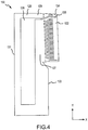
- an internal cooling configuration of an airfoil is shown as defined on a core 130 (also referred to as a casting core) similar to or identical to cast core 200 of FIG. 3 , in accordance with various embodiments.
- Casting may be used to form airfoil 100 of FIG. 2 .
- a core 130 may be formed.
- the core of the component wall may have a negative of the internal cooling features described herein.
- pedestals inside the airfoil may be defined by cavities 126 in core 130.
- passages in the airfoil are occupied by the material 128 of core 130.
- core 130 may be configured as a negative of the internal passages of airfoil 100.
- core 130 may be placed in a mold, and the material to form the internally cooled component may be deposited in the mold.
- the core 130 may be removed from the internally cooled component, leaving a cavity with the desired internal cooling features.
- Airfoil 100 (as well as other internally cooled components) may be made from an austenitic nickel-chromium-based alloy such as that sold under the trademark Inconel® which is available from Special Metals Corporation of New Hartford, New York, USA, or other materials capable of withstanding exhaust temperatures.
- core 130 may include a leading edge 131 and a trailing edge 133 that correspond to the interior surfaces of leading edge 104 and trailing edge 106 of FIG. 1 , respectively.
- Tip flag cavity 134 and trailing edge discharge cavity 132 may be defined by material 128 of core 130.
- Tip flag cavity 134 and trailing edge discharge cavity 132 may be disposed at trailing edge 133 of core 130.
- Leading edge cavity 129 may feed tip flag cavity 134.
- Trailing edge cavity 127 may feed trailing edge discharge cavity 132.
- a separate cooling channel may feed tip flag cavity 134 and trailing edge discharge cavity 132.
- coolant e.g., air
- y direction a radial direction with respect to axis A-A' when an airfoil is mounted to a rotor or stator
- the coolant may then move in the x direction (an axial direction axis A-A' when an airfoil is mounted to a rotor or stator) towards tip flag cavity 134 and trailing edge discharge cavity 132, where the coolant may be ejected from airfoil 100 to provide film cooling and limit back flow.
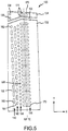
- tip flag cavity 134 and trailing edge discharge cavity 132 are shown, in accordance with various embodiments.
- Tip flag cavity 134 of core 130 may include pedestals of airfoil 100 (of FIG. 2 ) defined by openings in core 130.
- Pedestals on tip flag cavity 134 may have a depth (into and out of the page) greater than the depth of pedestals on trailing edge discharge cavity 132.
- pedestals on tip flag cavity 134 may comprise a depth of 0.02 inches (0.5 mm) and pedestals on trailing edge discharge cavity 132 may comprise a depth of 0.012 inches (0.30 mm).
- forward pedestal 138 and forward pedestal 139 may be aligned in the y direction (i.e., a radial direction when airfoil 100 is mounted to a rotor or stator).
- Forward pedestal 138 and forward pedestal 139 may have the same cylindrical geometry and be disposed at an intake to tip flag cavity 134.
- the forward pedestals may be disposed forward of spear pedestal 170.
- Spear pedestal 170 may define discharge slots 171 extending in the x direction above and below (in the y direction) spear pedestal 170.
- the trailing edge 106 of airfoil 100 (of FIG. 2 ) is represented by the broken line labeled A/F TE.
- discharge slots 171 may include an exhaust port at the intersection of spear pedestal 170 and A/F TE.
- separation 135 may be defined between tip flag cavity 134 and trailing edge discharge cavity 132.
- separation 135 may be filled with material to define tip flag cavity 134 and trailing edge discharge cavity 132.
- Trailing edge discharge cavity 132 may include four vertical (in the y direction) rows of pedestals. Forward racetrack row 140, aft racetrack row 142, circular row 144, and spear row 146. Each row may comprise of a plurality of pedestals aligned in the y direction.
- forward racetrack row 140 may comprise a plurality of racetrack pedestals 160.
- Racetrack pedestals 160 may be elongated in the y direction with circular bottom and top contours (in the y direction).
- the racetrack pedestals may be aligned in the y direction with a shortened racetrack pedestal 162 disposed at the top (in the y direction) of forward racetrack row 140 of trailing edge discharge cavity 132.
- aft racetrack row 142 may comprise a plurality of racetrack pedestals 166.
- Racetrack pedestals 166 may be elongated in the y direction with circular bottom and top contours (in the y direction).
- Racetrack pedestals 166 may be aligned in the y direction with a shortened racetrack pedestal 164 disposed at the bottom (in the y direction) of aft racetrack row 142 of trailing edge discharge cavity 132.
- Racetrack pedestals of forward racetrack row 140 may be staggered with racetrack pedestals of aft racetrack row 142 so that the openings between adjacent racetrack pedestals 160 (of forward racetrack row 140) generally do not align in the x direction with the openings between adjacent racetrack pedestals 166 (of aft racetrack row 142).
- circular row 144 may include a plurality of circular pedestals 168 aligned in the y direction.
- Circular pedestals 168 may have a circular geometry.
- Circular pedestals 168 may also be disposed aft of forward racetrack row 140, aft of aft racetrack row 142, and forward of spear row 146.
- the pitch and diameter of circular pedestals 168 may be selected so that every other circular pedestal 168 aligns in the x direction with an opening between adjacent racetrack pedestals 166 of aft racetrack row 142.
- spear row 146 may be disposed aft of circular row 144.
- Spear row may comprise a row of spear pedestals 170.
- Spear pedestals may comprise a spear geometry having a greater width (in the y direction) at a forward portion of the spear pedestal than at an aft portion of the spear pedestal, as described below with reference to FIG. 6B .
- Different spear pedestals 170 in spear row 146 may include substantially symmetric lengths (in the x direction) and widths (in the y direction). Spear pedestals in spear row 146 may have a pitch and dimensions such that each spear pedestal 170 aligns in the x direction with an opening between adjacent circular pedestals 168.
- Exemplary dimension ranges and dimensions of the pedestals in each row are provided in tables T1 and T2 below.
- the dimensions in tables T1 and T2 may be varied by +/-5% and may also vary by manufacturing tolerances. Additionally, the dimensions may be scaled with the dimensions of a core and/or airfoil.
- the shortened racetrack pedestals may have the same diameter and as the racetrack pedestals in the same row with a shorter height. Height and pitch are defined in the y direction. Blockage is the arithmetic equivalent to height divided by pitch and is thus the blockage percentage in the y direction.
- Table T1 - Exemplary dimensions of pedestals in each row.
- Forward pedestal 138 and forward pedestal 139 of tip flag cavity 134 may be aligned in the y direction and have substantially the same diameter.
- the center of the forward pedestals (disposed on row center line 180) may be forward of the center of the forward circular portion (disposed on row center line 182) of spear pedestal 136 by a distance D 1 in the x direction.
- distance D 1 may be 0.165 inches (4.2 mm), 0.16 - 0.17 inches (4.0 - 4.3 mm), or 0.15 - 0.18 inches (3.8 - 4.6 mm).
- the center of the forward circular portion (disposed on row center line 182) of spear pedestal 136 may be forward of A/F TE by a distance D 2 in the x direction.
- Distance D 2 may be, for example, 0.05 inches (1.3 mm), 0.04 - 0.06 inches (1.0 - 1.5 mm), or 0.03 - 0.07 inches (0.76 - 1.8 mm).
- shortened racetrack pedestal 162 may be aligned with racetrack pedestals 160 in the y direction with the center of the pedestals aligned on row center line 184.
- racetrack pedestals 166 may be aligned in the y direction with the center of racetrack pedestals 166 aligned on row center line 186.
- the center of racetrack pedestals 160 and shortened racetrack pedestals 162 may be forward of the center of racetrack pedestals 166 by a distance D 3 in the x direction.
- row center line 184 may be forward of row center line 186 by distance D 3 .
- D 3 may be, for example, 0.50 inches (1.3 mm), 0.45 - 0.55 inches (11.4 - 14.0 mm), or 0.4 - 0.6 inches (10.2 - 15.2 mm).
- circular pedestals 168 may be aligned in the y direction with the center of circular pedestals 168 aligned on row center line 188.
- the center of circular pedestals 168 may be aft of the center of racetrack pedestals 166 by a distance D 4 in the x direction.
- row center line 188 may be aft of row center line 186 by distance D 4 .
- Distance D 4 may be, for example, 0.0505 inches (1.3 mm), 0.045 - 0.055 inches (1.1 - 1.4 mm), or 0.04 - 0.06 inches (1.0 - 1.5 mm).
- spear pedestals 170 of trailing edge discharge cavity 132 may be aligned with spear pedestal 1436 of tip flag cavity 134 in the y direction.
- Circular pedestals 168 may be aligned in the y direction with the center of circular pedestals 168 (disposed on row center line 188) forward of the center of the forward circular portion (disposed on row center line 182) of spear pedestal 136 by a distance D 6 .
- D 6 may be, for example, 0.051 inches (1.3 mm), 0.045 - 0.055 inches (1.1 - 1.4 mm), or 0.04 - 0.06 inches (1.0 - 1.5 mm).
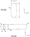
- Racetrack pedestals may have a racetrack shape.
- the racetrack shape may be defined by two parallel surfaces joined on either end by a half circular end.
- the half circular end may have a diameter equal to width W 1 .
- the parallel surfaces may be separated by width W 1 in the x direction.
- Width W 1 may be, for example, 0.025 inches (0.64 mm).
- the racetrack pedestals may also comprise a height H 1 in the y direction. Height H 1 may be, for example, 0.072 inches (1.8 mm) or in a range such as 0.06-0.08 inches (1.5 - 2.0 mm).
- spear pedestals 170 may differ from racetrack pedestals 160 in geometry.
- Spear pedestals may comprise a forward circular portion 190 having a diameter H 2 and an aft parallel portion 192 having a height H 3 , with H 3 less than H 1 .
- Aft parallel portion 192 may be connected to forward circular portion 190 by non-parallel surfaces 194.
- Aft parallel portion 192 may also comprise aft circular portion 196 having a diameter of H 3 , which is the same as the height H 3 of aft parallel portion 192.
- the values of H 2 and H 3 may be, for example, 0.026 inches (0.66 mm) and 0.0225 inches (0.57 mm), respectively.
- H 2 and H 3 may also be in a range with H 2 greater than H 3 such as, for example, H 2 ranging from 0.021 - 0.031 inches (0.53 - 0.79) and H 3 ranging from 0.0175 - 0.0275 inches (0.44 - 0.70 mm).
- references to "one embodiment”, “an embodiment”, “an example embodiment”, etc. indicate that the embodiment described may include a particular feature, structure, or characteristic, but every embodiment may not necessarily include the particular feature, structure, or characteristic. Moreover, such phrases are not necessarily referring to the same embodiment. Further, when a particular feature, structure, or characteristic is described in connection with an embodiment, it is submitted that it is within the knowledge of one skilled in the art to affect such feature, structure, or characteristic in connection with other embodiments whether or not explicitly described. After reading the description, it will be apparent to one skilled in the relevant art(s) how to implement the disclosure in alternative embodiments.
- the terms “comprises”, “comprising”, or any other variation thereof, are intended to cover a non-exclusive inclusion, such that a process, method, article, or apparatus that comprises a list of elements does not include only those elements but may include other elements not expressly listed or inherent to such process, method, article, or apparatus.
Landscapes
- Engineering & Computer Science (AREA)
- Mechanical Engineering (AREA)
- General Engineering & Computer Science (AREA)
- Chemical & Material Sciences (AREA)
- Combustion & Propulsion (AREA)
- Turbine Rotor Nozzle Sealing (AREA)
Applications Claiming Priority (1)
| Application Number | Priority Date | Filing Date | Title |
|---|---|---|---|
| US15/096,243 US10508552B2 (en) | 2016-04-11 | 2016-04-11 | Internally cooled airfoil |
Publications (2)
| Publication Number | Publication Date |
|---|---|
| EP3241992A1 true EP3241992A1 (fr) | 2017-11-08 |
| EP3241992B1 EP3241992B1 (fr) | 2019-01-30 |
Family
ID=58536911
Family Applications (1)
| Application Number | Title | Priority Date | Filing Date |
|---|---|---|---|
| EP17166119.2A Active EP3241992B1 (fr) | 2016-04-11 | 2017-04-11 | Surface portante à refroidissement interne |
Country Status (2)
| Country | Link |
|---|---|
| US (2) | US10508552B2 (fr) |
| EP (1) | EP3241992B1 (fr) |
Families Citing this family (2)
| Publication number | Priority date | Publication date | Assignee | Title |
|---|---|---|---|---|
| FR3066530B1 (fr) * | 2017-05-22 | 2020-03-27 | Safran Aircraft Engines | Aube pour turbine de turbomachine comprenant une configuration optimisee de cavites internes de circulation d'air de refroidissement |
| US11168570B1 (en) * | 2020-08-27 | 2021-11-09 | Raytheon Technologies Corporation | Cooling arrangement for gas turbine engine components |
Citations (3)
| Publication number | Priority date | Publication date | Assignee | Title |
|---|---|---|---|---|
| US20130243575A1 (en) * | 2012-03-13 | 2013-09-19 | United Technologies Corporation | Cooling pedestal array |
| US20130251538A1 (en) * | 2012-03-20 | 2013-09-26 | United Technologies Corporation | Trailing edge cooling |
| EP2713012A1 (fr) * | 2012-09-26 | 2014-04-02 | Rolls-Royce plc | Composant de moteur à turbine à gaz |
Family Cites Families (5)
| Publication number | Priority date | Publication date | Assignee | Title |
|---|---|---|---|---|
| US5931638A (en) * | 1997-08-07 | 1999-08-03 | United Technologies Corporation | Turbomachinery airfoil with optimized heat transfer |
| US6179565B1 (en) * | 1999-08-09 | 2001-01-30 | United Technologies Corporation | Coolable airfoil structure |
| US7014424B2 (en) * | 2003-04-08 | 2006-03-21 | United Technologies Corporation | Turbine element |
| US7125225B2 (en) * | 2004-02-04 | 2006-10-24 | United Technologies Corporation | Cooled rotor blade with vibration damping device |
| US7607891B2 (en) * | 2006-10-23 | 2009-10-27 | United Technologies Corporation | Turbine component with tip flagged pedestal cooling |
-
2016
- 2016-04-11 US US15/096,243 patent/US10508552B2/en active Active
-
2017
- 2017-04-11 EP EP17166119.2A patent/EP3241992B1/fr active Active
-
2019
- 2019-11-06 US US16/675,879 patent/US10830054B2/en active Active
Patent Citations (3)
| Publication number | Priority date | Publication date | Assignee | Title |
|---|---|---|---|---|
| US20130243575A1 (en) * | 2012-03-13 | 2013-09-19 | United Technologies Corporation | Cooling pedestal array |
| US20130251538A1 (en) * | 2012-03-20 | 2013-09-26 | United Technologies Corporation | Trailing edge cooling |
| EP2713012A1 (fr) * | 2012-09-26 | 2014-04-02 | Rolls-Royce plc | Composant de moteur à turbine à gaz |
Also Published As
| Publication number | Publication date |
|---|---|
| US10508552B2 (en) | 2019-12-17 |
| US20200088042A1 (en) | 2020-03-19 |
| US20170292384A1 (en) | 2017-10-12 |
| EP3241992B1 (fr) | 2019-01-30 |
| US10830054B2 (en) | 2020-11-10 |
Similar Documents
| Publication | Publication Date | Title |
|---|---|---|
| EP3074606B1 (fr) | Aube de moteur à turbine à gaz présentant un sillon de bord d'attaque et un refroidissement par impact | |
| EP3063389B1 (fr) | Socles de distribution de films refroidis par un trou | |
| US20140294562A1 (en) | Strut for a gas turbine engine | |
| US20190218916A1 (en) | Gas turbine engine airfoil trailing edge suction side cooling | |
| EP3505726B1 (fr) | Ensemble d'aube pour moteur de turbine à gaz | |
| CN103184894A (zh) | 涡轮机转子叶片平台冷却 | |
| EP3205821A1 (fr) | Refroidissement pour le bord de fuite d'une aube de turbine | |
| EP3477058B1 (fr) | Circuit de refroidissement de profil aérodynamique | |
| CA2944392A1 (fr) | Pale de turbine | |
| US10767490B2 (en) | Hot section engine components having segment gap discharge holes | |
| US10513931B2 (en) | Cooling systems and internally-cooled engine parts having an impingement cavity with an undulating internal surface | |
| EP3296517B1 (fr) | Gestion thermique de corps central avant de turboréacteur à double flux à engrenage | |
| US10641100B2 (en) | Gas turbine engine airfoil cooling passage configuration | |
| US10830054B2 (en) | Internally cooled airfoil | |
| EP3453831A2 (fr) | Profil aérodynamique comportant des socles profilés de paroi d'extrémité | |
| US20180051571A1 (en) | Airfoil for a turbine engine with porous rib | |
| EP3354852B1 (fr) | Composants de moteur à turbine à gaz avec refroidissement interne | |
| US10801333B2 (en) | Airfoils, cores, and methods of manufacture for forming airfoils having fluidly connected platform cooling circuits | |
| EP3043031A1 (fr) | Agencement d'aubes de redresseur, set d'aubes de redresseur et procédé de fabrication d'un agencement d'aubes de redresseur | |
| EP3477053B1 (fr) | Circuit de refroidissement de profil aérodynamique d'une turbine á gaz et procédé de fabrication | |
| EP4477841A1 (fr) | Aube pour un moteur à turbine à gaz, aube mobile de turbine pour l'utilisation dans un moteur à turbine à gaz et procédé de mise à disposition d'un refroidissement interne à une aube d'un moteur à turbine à gaz | |
| US20260110311A1 (en) | Two stream diffuser integrated as a single unit for use in a turbofan jet engine | |
| EP4477842A1 (fr) | Aube pour un moteur à turbine à gaz |
Legal Events
| Date | Code | Title | Description |
|---|---|---|---|
| PUAI | Public reference made under article 153(3) epc to a published international application that has entered the european phase |
Free format text: ORIGINAL CODE: 0009012 |
|
| STAA | Information on the status of an ep patent application or granted ep patent |
Free format text: STATUS: THE APPLICATION HAS BEEN PUBLISHED |
|
| AK | Designated contracting states |
Kind code of ref document: A1 Designated state(s): AL AT BE BG CH CY CZ DE DK EE ES FI FR GB GR HR HU IE IS IT LI LT LU LV MC MK MT NL NO PL PT RO RS SE SI SK SM TR |
|
| AX | Request for extension of the european patent |
Extension state: BA ME |
|
| STAA | Information on the status of an ep patent application or granted ep patent |
Free format text: STATUS: REQUEST FOR EXAMINATION WAS MADE |
|
| 17P | Request for examination filed |
Effective date: 20180416 |
|
| RBV | Designated contracting states (corrected) |
Designated state(s): AL AT BE BG CH CY CZ DE DK EE ES FI FR GB GR HR HU IE IS IT LI LT LU LV MC MK MT NL NO PL PT RO RS SE SI SK SM TR |
|
| RIC1 | Information provided on ipc code assigned before grant |
Ipc: F01D 25/12 20060101ALI20180515BHEP Ipc: F01D 5/18 20060101AFI20180515BHEP |
|
| GRAP | Despatch of communication of intention to grant a patent |
Free format text: ORIGINAL CODE: EPIDOSNIGR1 |
|
| STAA | Information on the status of an ep patent application or granted ep patent |
Free format text: STATUS: GRANT OF PATENT IS INTENDED |
|
| INTG | Intention to grant announced |
Effective date: 20180801 |
|
| RIN1 | Information on inventor provided before grant (corrected) |
Inventor name: JARIWALA, PARTH Inventor name: AUXIER, JAMES T. Inventor name: TELLER, BRET M. |
|
| GRAS | Grant fee paid |
Free format text: ORIGINAL CODE: EPIDOSNIGR3 |
|
| GRAA | (expected) grant |
Free format text: ORIGINAL CODE: 0009210 |
|
| STAA | Information on the status of an ep patent application or granted ep patent |
Free format text: STATUS: THE PATENT HAS BEEN GRANTED |
|
| AK | Designated contracting states |
Kind code of ref document: B1 Designated state(s): AL AT BE BG CH CY CZ DE DK EE ES FI FR GB GR HR HU IE IS IT LI LT LU LV MC MK MT NL NO PL PT RO RS SE SI SK SM TR |
|
| REG | Reference to a national code |
Ref country code: GB Ref legal event code: FG4D |
|
| REG | Reference to a national code |
Ref country code: CH Ref legal event code: EP |
|
| REG | Reference to a national code |
Ref country code: AT Ref legal event code: REF Ref document number: 1093432 Country of ref document: AT Kind code of ref document: T Effective date: 20190215 |
|
| REG | Reference to a national code |
Ref country code: IE Ref legal event code: FG4D |
|
| REG | Reference to a national code |
Ref country code: DE Ref legal event code: R096 Ref document number: 602017001969 Country of ref document: DE |
|
| REG | Reference to a national code |
Ref country code: LT Ref legal event code: MG4D |
|
| REG | Reference to a national code |
Ref country code: NL Ref legal event code: MP Effective date: 20190130 |
|
| PG25 | Lapsed in a contracting state [announced via postgrant information from national office to epo] |
Ref country code: NL Free format text: LAPSE BECAUSE OF FAILURE TO SUBMIT A TRANSLATION OF THE DESCRIPTION OR TO PAY THE FEE WITHIN THE PRESCRIBED TIME-LIMIT Effective date: 20190130 Ref country code: PT Free format text: LAPSE BECAUSE OF FAILURE TO SUBMIT A TRANSLATION OF THE DESCRIPTION OR TO PAY THE FEE WITHIN THE PRESCRIBED TIME-LIMIT Effective date: 20190530 Ref country code: SE Free format text: LAPSE BECAUSE OF FAILURE TO SUBMIT A TRANSLATION OF THE DESCRIPTION OR TO PAY THE FEE WITHIN THE PRESCRIBED TIME-LIMIT Effective date: 20190130 Ref country code: FI Free format text: LAPSE BECAUSE OF FAILURE TO SUBMIT A TRANSLATION OF THE DESCRIPTION OR TO PAY THE FEE WITHIN THE PRESCRIBED TIME-LIMIT Effective date: 20190130 Ref country code: NO Free format text: LAPSE BECAUSE OF FAILURE TO SUBMIT A TRANSLATION OF THE DESCRIPTION OR TO PAY THE FEE WITHIN THE PRESCRIBED TIME-LIMIT Effective date: 20190430 Ref country code: LT Free format text: LAPSE BECAUSE OF FAILURE TO SUBMIT A TRANSLATION OF THE DESCRIPTION OR TO PAY THE FEE WITHIN THE PRESCRIBED TIME-LIMIT Effective date: 20190130 Ref country code: PL Free format text: LAPSE BECAUSE OF FAILURE TO SUBMIT A TRANSLATION OF THE DESCRIPTION OR TO PAY THE FEE WITHIN THE PRESCRIBED TIME-LIMIT Effective date: 20190130 Ref country code: ES Free format text: LAPSE BECAUSE OF FAILURE TO SUBMIT A TRANSLATION OF THE DESCRIPTION OR TO PAY THE FEE WITHIN THE PRESCRIBED TIME-LIMIT Effective date: 20190130 |
|
| REG | Reference to a national code |
Ref country code: AT Ref legal event code: MK05 Ref document number: 1093432 Country of ref document: AT Kind code of ref document: T Effective date: 20190130 |
|
| PG25 | Lapsed in a contracting state [announced via postgrant information from national office to epo] |
Ref country code: IS Free format text: LAPSE BECAUSE OF FAILURE TO SUBMIT A TRANSLATION OF THE DESCRIPTION OR TO PAY THE FEE WITHIN THE PRESCRIBED TIME-LIMIT Effective date: 20190530 Ref country code: HR Free format text: LAPSE BECAUSE OF FAILURE TO SUBMIT A TRANSLATION OF THE DESCRIPTION OR TO PAY THE FEE WITHIN THE PRESCRIBED TIME-LIMIT Effective date: 20190130 Ref country code: GR Free format text: LAPSE BECAUSE OF FAILURE TO SUBMIT A TRANSLATION OF THE DESCRIPTION OR TO PAY THE FEE WITHIN THE PRESCRIBED TIME-LIMIT Effective date: 20190501 Ref country code: LV Free format text: LAPSE BECAUSE OF FAILURE TO SUBMIT A TRANSLATION OF THE DESCRIPTION OR TO PAY THE FEE WITHIN THE PRESCRIBED TIME-LIMIT Effective date: 20190130 Ref country code: RS Free format text: LAPSE BECAUSE OF FAILURE TO SUBMIT A TRANSLATION OF THE DESCRIPTION OR TO PAY THE FEE WITHIN THE PRESCRIBED TIME-LIMIT Effective date: 20190130 Ref country code: BG Free format text: LAPSE BECAUSE OF FAILURE TO SUBMIT A TRANSLATION OF THE DESCRIPTION OR TO PAY THE FEE WITHIN THE PRESCRIBED TIME-LIMIT Effective date: 20190430 |
|
| PG25 | Lapsed in a contracting state [announced via postgrant information from national office to epo] |
Ref country code: CZ Free format text: LAPSE BECAUSE OF FAILURE TO SUBMIT A TRANSLATION OF THE DESCRIPTION OR TO PAY THE FEE WITHIN THE PRESCRIBED TIME-LIMIT Effective date: 20190130 Ref country code: IT Free format text: LAPSE BECAUSE OF FAILURE TO SUBMIT A TRANSLATION OF THE DESCRIPTION OR TO PAY THE FEE WITHIN THE PRESCRIBED TIME-LIMIT Effective date: 20190130 Ref country code: RO Free format text: LAPSE BECAUSE OF FAILURE TO SUBMIT A TRANSLATION OF THE DESCRIPTION OR TO PAY THE FEE WITHIN THE PRESCRIBED TIME-LIMIT Effective date: 20190130 Ref country code: EE Free format text: LAPSE BECAUSE OF FAILURE TO SUBMIT A TRANSLATION OF THE DESCRIPTION OR TO PAY THE FEE WITHIN THE PRESCRIBED TIME-LIMIT Effective date: 20190130 Ref country code: DK Free format text: LAPSE BECAUSE OF FAILURE TO SUBMIT A TRANSLATION OF THE DESCRIPTION OR TO PAY THE FEE WITHIN THE PRESCRIBED TIME-LIMIT Effective date: 20190130 Ref country code: AL Free format text: LAPSE BECAUSE OF FAILURE TO SUBMIT A TRANSLATION OF THE DESCRIPTION OR TO PAY THE FEE WITHIN THE PRESCRIBED TIME-LIMIT Effective date: 20190130 Ref country code: SK Free format text: LAPSE BECAUSE OF FAILURE TO SUBMIT A TRANSLATION OF THE DESCRIPTION OR TO PAY THE FEE WITHIN THE PRESCRIBED TIME-LIMIT Effective date: 20190130 |
|
| REG | Reference to a national code |
Ref country code: DE Ref legal event code: R097 Ref document number: 602017001969 Country of ref document: DE |
|
| PG25 | Lapsed in a contracting state [announced via postgrant information from national office to epo] |
Ref country code: SM Free format text: LAPSE BECAUSE OF FAILURE TO SUBMIT A TRANSLATION OF THE DESCRIPTION OR TO PAY THE FEE WITHIN THE PRESCRIBED TIME-LIMIT Effective date: 20190130 |
|
| PLBE | No opposition filed within time limit |
Free format text: ORIGINAL CODE: 0009261 |
|
| STAA | Information on the status of an ep patent application or granted ep patent |
Free format text: STATUS: NO OPPOSITION FILED WITHIN TIME LIMIT |
|
| REG | Reference to a national code |
Ref country code: BE Ref legal event code: MM Effective date: 20190430 |
|
| PG25 | Lapsed in a contracting state [announced via postgrant information from national office to epo] |
Ref country code: AT Free format text: LAPSE BECAUSE OF FAILURE TO SUBMIT A TRANSLATION OF THE DESCRIPTION OR TO PAY THE FEE WITHIN THE PRESCRIBED TIME-LIMIT Effective date: 20190130 Ref country code: LU Free format text: LAPSE BECAUSE OF NON-PAYMENT OF DUE FEES Effective date: 20190411 Ref country code: MC Free format text: LAPSE BECAUSE OF FAILURE TO SUBMIT A TRANSLATION OF THE DESCRIPTION OR TO PAY THE FEE WITHIN THE PRESCRIBED TIME-LIMIT Effective date: 20190130 |
|
| 26N | No opposition filed |
Effective date: 20191031 |
|
| PG25 | Lapsed in a contracting state [announced via postgrant information from national office to epo] |
Ref country code: SI Free format text: LAPSE BECAUSE OF FAILURE TO SUBMIT A TRANSLATION OF THE DESCRIPTION OR TO PAY THE FEE WITHIN THE PRESCRIBED TIME-LIMIT Effective date: 20190130 Ref country code: BE Free format text: LAPSE BECAUSE OF NON-PAYMENT OF DUE FEES Effective date: 20190430 |
|
| PG25 | Lapsed in a contracting state [announced via postgrant information from national office to epo] |
Ref country code: TR Free format text: LAPSE BECAUSE OF FAILURE TO SUBMIT A TRANSLATION OF THE DESCRIPTION OR TO PAY THE FEE WITHIN THE PRESCRIBED TIME-LIMIT Effective date: 20190130 |
|
| PG25 | Lapsed in a contracting state [announced via postgrant information from national office to epo] |
Ref country code: IE Free format text: LAPSE BECAUSE OF NON-PAYMENT OF DUE FEES Effective date: 20190411 |
|
| REG | Reference to a national code |
Ref country code: CH Ref legal event code: PL |
|
| PG25 | Lapsed in a contracting state [announced via postgrant information from national office to epo] |
Ref country code: LI Free format text: LAPSE BECAUSE OF NON-PAYMENT OF DUE FEES Effective date: 20200430 Ref country code: CH Free format text: LAPSE BECAUSE OF NON-PAYMENT OF DUE FEES Effective date: 20200430 |
|
| PG25 | Lapsed in a contracting state [announced via postgrant information from national office to epo] |
Ref country code: CY Free format text: LAPSE BECAUSE OF FAILURE TO SUBMIT A TRANSLATION OF THE DESCRIPTION OR TO PAY THE FEE WITHIN THE PRESCRIBED TIME-LIMIT Effective date: 20190130 |
|
| PG25 | Lapsed in a contracting state [announced via postgrant information from national office to epo] |
Ref country code: MT Free format text: LAPSE BECAUSE OF FAILURE TO SUBMIT A TRANSLATION OF THE DESCRIPTION OR TO PAY THE FEE WITHIN THE PRESCRIBED TIME-LIMIT Effective date: 20190130 Ref country code: HU Free format text: LAPSE BECAUSE OF FAILURE TO SUBMIT A TRANSLATION OF THE DESCRIPTION OR TO PAY THE FEE WITHIN THE PRESCRIBED TIME-LIMIT; INVALID AB INITIO Effective date: 20170411 |
|
| PG25 | Lapsed in a contracting state [announced via postgrant information from national office to epo] |
Ref country code: MK Free format text: LAPSE BECAUSE OF FAILURE TO SUBMIT A TRANSLATION OF THE DESCRIPTION OR TO PAY THE FEE WITHIN THE PRESCRIBED TIME-LIMIT Effective date: 20190130 |
|
| REG | Reference to a national code |
Ref country code: DE Ref legal event code: R081 Ref document number: 602017001969 Country of ref document: DE Owner name: RAYTHEON TECHNOLOGIES CORPORATION (N.D.GES.D.S, US Free format text: FORMER OWNER: UNITED TECHNOLOGIES CORPORATION, FARMINGTON, CONN., US Ref country code: DE Ref legal event code: R081 Ref document number: 602017001969 Country of ref document: DE Owner name: RTX CORPORATION (N.D.GES.D. STAATES DELAWARE),, US Free format text: FORMER OWNER: UNITED TECHNOLOGIES CORPORATION, FARMINGTON, CONN., US |
|
| P01 | Opt-out of the competence of the unified patent court (upc) registered |
Effective date: 20230520 |
|
| PGFP | Annual fee paid to national office [announced via postgrant information from national office to epo] |
Ref country code: DE Payment date: 20250319 Year of fee payment: 9 |
|
| REG | Reference to a national code |
Ref country code: DE Ref legal event code: R081 Ref document number: 602017001969 Country of ref document: DE Owner name: RTX CORPORATION (N.D.GES.D. STAATES DELAWARE),, US Free format text: FORMER OWNER: RAYTHEON TECHNOLOGIES CORPORATION (N.D.GES.D.STAATES DELAWARE), ARLINGTON, VA, US |
|
| PGFP | Annual fee paid to national office [announced via postgrant information from national office to epo] |
Ref country code: GB Payment date: 20260319 Year of fee payment: 10 |
|
| PGFP | Annual fee paid to national office [announced via postgrant information from national office to epo] |
Ref country code: FR Payment date: 20260320 Year of fee payment: 10 |